EP2665652B1 - Reefing device - Google Patents
Reefing device Download PDFInfo
- Publication number
- EP2665652B1 EP2665652B1 EP12701635.0A EP12701635A EP2665652B1 EP 2665652 B1 EP2665652 B1 EP 2665652B1 EP 12701635 A EP12701635 A EP 12701635A EP 2665652 B1 EP2665652 B1 EP 2665652B1
- Authority
- EP
- European Patent Office
- Prior art keywords
- reefing
- finger
- engagement
- tubular film
- advancing means
- Prior art date
- Legal status (The legal status is an assumption and is not a legal conclusion. Google has not performed a legal analysis and makes no representation as to the accuracy of the status listed.)
- Active
Links
Images





Classifications
-
- B—PERFORMING OPERATIONS; TRANSPORTING
- B65—CONVEYING; PACKING; STORING; HANDLING THIN OR FILAMENTARY MATERIAL
- B65B—MACHINES, APPARATUS OR DEVICES FOR, OR METHODS OF, PACKAGING ARTICLES OR MATERIALS; UNPACKING
- B65B9/00—Enclosing successive articles, or quantities of material, e.g. liquids or semiliquids, in flat, folded, or tubular webs of flexible sheet material; Subdividing filled flexible tubes to form packages
- B65B9/10—Enclosing successive articles, or quantities of material, in preformed tubular webs, or in webs formed into tubes around filling nozzles, e.g. extruded tubular webs
- B65B9/13—Enclosing successive articles, or quantities of material, in preformed tubular webs, or in webs formed into tubes around filling nozzles, e.g. extruded tubular webs the preformed tubular webs being supplied in a flattened state
- B65B9/14—Devices for distending tubes supplied in the flattened state
-
- B—PERFORMING OPERATIONS; TRANSPORTING
- B65—CONVEYING; PACKING; STORING; HANDLING THIN OR FILAMENTARY MATERIAL
- B65B—MACHINES, APPARATUS OR DEVICES FOR, OR METHODS OF, PACKAGING ARTICLES OR MATERIALS; UNPACKING
- B65B9/00—Enclosing successive articles, or quantities of material, e.g. liquids or semiliquids, in flat, folded, or tubular webs of flexible sheet material; Subdividing filled flexible tubes to form packages
- B65B9/10—Enclosing successive articles, or quantities of material, in preformed tubular webs, or in webs formed into tubes around filling nozzles, e.g. extruded tubular webs
-
- B—PERFORMING OPERATIONS; TRANSPORTING
- B65—CONVEYING; PACKING; STORING; HANDLING THIN OR FILAMENTARY MATERIAL
- B65B—MACHINES, APPARATUS OR DEVICES FOR, OR METHODS OF, PACKAGING ARTICLES OR MATERIALS; UNPACKING
- B65B9/00—Enclosing successive articles, or quantities of material, e.g. liquids or semiliquids, in flat, folded, or tubular webs of flexible sheet material; Subdividing filled flexible tubes to form packages
- B65B9/10—Enclosing successive articles, or quantities of material, in preformed tubular webs, or in webs formed into tubes around filling nozzles, e.g. extruded tubular webs
- B65B9/13—Enclosing successive articles, or quantities of material, in preformed tubular webs, or in webs formed into tubes around filling nozzles, e.g. extruded tubular webs the preformed tubular webs being supplied in a flattened state
-
- B—PERFORMING OPERATIONS; TRANSPORTING
- B65—CONVEYING; PACKING; STORING; HANDLING THIN OR FILAMENTARY MATERIAL
- B65B—MACHINES, APPARATUS OR DEVICES FOR, OR METHODS OF, PACKAGING ARTICLES OR MATERIALS; UNPACKING
- B65B9/00—Enclosing successive articles, or quantities of material, e.g. liquids or semiliquids, in flat, folded, or tubular webs of flexible sheet material; Subdividing filled flexible tubes to form packages
- B65B9/10—Enclosing successive articles, or quantities of material, in preformed tubular webs, or in webs formed into tubes around filling nozzles, e.g. extruded tubular webs
- B65B9/13—Enclosing successive articles, or quantities of material, in preformed tubular webs, or in webs formed into tubes around filling nozzles, e.g. extruded tubular webs the preformed tubular webs being supplied in a flattened state
- B65B9/135—Enclosing successive articles, or quantities of material, in preformed tubular webs, or in webs formed into tubes around filling nozzles, e.g. extruded tubular webs the preformed tubular webs being supplied in a flattened state for palletised loads
-
- B—PERFORMING OPERATIONS; TRANSPORTING
- B65—CONVEYING; PACKING; STORING; HANDLING THIN OR FILAMENTARY MATERIAL
- B65B—MACHINES, APPARATUS OR DEVICES FOR, OR METHODS OF, PACKAGING ARTICLES OR MATERIALS; UNPACKING
- B65B9/00—Enclosing successive articles, or quantities of material, e.g. liquids or semiliquids, in flat, folded, or tubular webs of flexible sheet material; Subdividing filled flexible tubes to form packages
- B65B9/10—Enclosing successive articles, or quantities of material, in preformed tubular webs, or in webs formed into tubes around filling nozzles, e.g. extruded tubular webs
- B65B9/15—Enclosing successive articles, or quantities of material, in preformed tubular webs, or in webs formed into tubes around filling nozzles, e.g. extruded tubular webs the preformed tubular webs being stored on filling nozzles
- B65B9/18—Devices for storing tubular webs
Definitions
- the present invention concerns a reefing device with at least one reefing finger and at least one drive unit, which has an advancing means, which, for reefing a portion of tubular film, is brought into operative connection with the reefing finger, at least at the height of a point of engagement, while enclosing the portion of tubular film, and moves the portion of tubular film in relation to the reefing finger.
- the present invention also concerns a method for reefing a portion of tubular form with a reefing device according to the invention.
- Such reefing devices and methods are known per se e.g. from US 4473990 , or EP 1574432 . Some, are used for example in hood packaging installations. These may be installations which operate on the basis of what is known as the hood stretching process or the hood shrinking process. Both processes are distinguished by the fact that a portion of a tubular film is pulled or pushed over any desired cargo, or that the cargo is introduced into the portion of tubular film by means of a lifting table. This is referred to hereafter as wrapping of cargo.
- the wrapping of the cargo with a portion of tubular film generally serves for the packaging and transportability of the cargo and for securing it during loading and protecting it from the effects of weather.
- the portion of tubular film that is applied to the cargo may be designed not only as a hood but also, for example, as an upwardly open portion of tube in the manner of a banderole.
- the portion of tubular film is first reefed by means of a reefing device, to then be slipped over the cargo by the reefing device or by a separate drawing-over device and thereby unreefed.
- a supply of portions of tubular film laid in folds which is also referred to hereafter as a film store, is formed at the bottom of the reefing fingers. If the reefing device is also used for the drawing over, the reefing device is moved in relation to the cargo, possibly after stretching the portion of tubular film. During this relative movement, the portion of tubular film is pulled off from the reefing fingers, also referred to as unreefed.
- reefing as reefing progresses, or the like, also refer to unreefing.
- the reefing fingers are usually introduced into the opened portion of tubular film from below, or the latter is lowered onto the reefing fingers.
- reefing devices of the generic type have at least one drive unit of any desired design, with an advancing means such as for instance a motor-operated conveyor belt or a reefing roller drive.
- the drive unit For reefing the portion of tubular film, the drive unit is brought into operative connection with the reefing finger, at least at the height of a point of engagement, while enclosing the portion of tubular film. This may take place, for example, by pressing the drive device or the advancing means against the reefing finger at a single point. Then, by means of the drive unit or the advancing means, the portion of tubular film can be moved in relation to the reefing fingers under a certain pressing pressure and pushed onto or pulled off again from said fingers. There is therefore generally a frictional connection between the drive unit or the advancing means and the portion of tube. At least one point of engagement should be understood as meaning at least one location which comprises at least one point or a number of points, for example in the manner of a line or surface area.
- the invention is therefore based on the object of improving the reefing of a portion of tubular film, so that altogether improved quality of the wrapping of the cargo is obtained.
- the reefing device according the invention differs from the reefing device described at the beginning in that the position of the at least one point of engagement can be changed along the reefing finger as reefing progresses. Unlike in the case of the previously known devices, the position of the point of engagement is adapted during the reefing to the extent of the film store. Consequently, a substantially constant distance can be maintained between the film store and the point of engagement, thereby bringing about always the same film formation during the reefing, and optimum unfolding during the unreefing of the portion of tubular film.
- the position of the lowermost point of engagement can be changed along the reefing finger as reefing progresses.
- the lowermost point of engagement should be understood here as meaning the point of engagement which is closest to the film store, or the bottom of the reefing finger. It is consequently possible for only the lowermost point of engagement to be changed in its position along the longitudinal axis of the reefing finger, while another point of engagement remains unchanged in its position.
- This has the advantage that the drive means can act on the portion of tubular film at a number of places, and consequently securely, with a relatively low structural expenditure. Nevertheless, the positive effect of uniform fold formation during the reefing and uniform unfolding during the unreefing is obtained on account of the distance from the film store being kept as constant as possible.
- At least one opposing roller is fastened to the reefing finger in such a way that the opposing roller can be brought into operative connection with the advancing means during the reefing, while enclosing the portion of tubular film, and defines the point of engagement.
- the opposing roller reduces the friction between the reefing finger and the tubular film.
- the at least one opposing roller is fastened to the reefing finger in such a way that the position of the opposing roller on the reefing finger can be changed as reefing progresses.
- the point of engagement can be changed by changing the position of the opposing roller on the reefing finger.
- the at least one opposing roller is fastened to the reefing finger in such a way that it is longitudinally and/or transversely displaceable and/or pivotable with respect to the reefing finger.
- a movement longitudinally with respect to the reefing finger can be understood here as meaning a movement along the longitudinal axis of the reefing finger.
- a movement transverse to the reefing finger describes a movement transverse to the longitudinal axis of the reefing finger.
- the point of engagement can be created and removed again as required by a transverse displacement or corresponding pivoting of the opposing roller. It is also conceivable that a point of engagement is first created for example by a transverse movement of the opposing roller and is then changed in its position with respect to the reefing finger by a longitudinal movement of the opposing roller, before the point of engagement is removed again by a renewed transverse movement.
- a plurality of opposing rollers are arranged on the reefing finger in such a way that different opposing rollers can be brought into operative connection with the advancing means as reefing progresses. Consequently, a plurality of points of engagement can be created, it being possible for the position of the lowermost point of engagement to be changed by the successive setting up and successive removal of the operative connections of individual opposing rollers to the advancing means.
- At least one fixedly mounted opposing roller may be arranged at the upper end of the reefing finger.
- This opposing roller serves firstly for securely guiding the portion of film over the upper end of the reefing finger. It may, however, also be used for creating a point of engagement in the sense of the invention, that is whenever the drive unit can be brought into operative connection with it.
- the upper end of the reefing finger should be understood as meaning the end which is generally furthest away from the film store.
- the drive unit and/or the advancing means can be at least partially changed in its/their position in relation to the reefing finger. Consequently, the position of a point of engagement can be changed by changing the position of the drive unit or the advancing means in relation to the reefing finger.
- the advancing means may be a drive roller or a continuous belt.
- the advancing means comprises a number of drive rollers, which can, for example, also be activated asynchronously.
- the surface of the advancing means is profiled or coated in such a way that an ideal coefficient of friction is obtained for the advancement or movement of the portion of tubular film.
- the advancing means is pivotably and/or displaceably configured in such a way that, during the reefing, it can be brought into operative connection with the reefing finger, while enclosing the portion of tubular film, at different heights according to how much reefing has progressed.
- This has the advantage that the advancing means can be used to define at least one point of engagement, the position of which is changed by pivoting and/or displacing the advancing means. Consequently, the construction of the reefing finger can be kept relatively simple and does not have to be changed in comparison with conventional reefing fingers to realize the invention.
- the advancing means can be moved together with at least one opposing roller.
- the advancing means is pivotably and/or displaceably configured in such a way that, during the reefing, it is in operative connection with the at least one pivotable and/or displaceable opposing roller, while enclosing the portion of tubular film, according to how much reefing has progressed, while at least the position of the lowermost point of engagement is changed by displacing and pivoting the advancing means and the opposing roller.
- the at least one point of engagement is therefore defined both by the at least one opposing roller and by the advancing means and may be maintained on the film the whole time during reefing, while the position of the at least one point of engagement is changed. This allows there to be a distance between the lowermost point of engagement and the film store that is largely constant and as small as possible. In this way, an optimum reefing result can be achieved.
- the advancing means is pivotably and/or displaceably configured in such a way that, during the reefing, it can be brought into operative connection with different opposing rollers, while enclosing the portion of tubular film, according to how much reefing has progressed. Consequently, the position particularly of the lowermost point of engagement can be changed intermittently, in that the advancing means is brought into operative connection with different opposing rollers one after the other.
- the reefing device may be designed in such a way that it comprises a plurality of reefing fingers and assigned drive units, it being possible for the individual reefing finger to be individually activated by its assigned drive unit.
- four reefing fingers may be provided, with four respectively assigned drive units, which are respectively assigned to the corners of a typical packaging unit, such as for example a pallet.
- the individual reefing fingers may be operated by their drive unit in isolation and separately from one another, for example if it is desired to achieve a specific fold formation, for instance to strengthen the package to be produced.
- the reefing operation may also be adapted to the respective circumstances, for example a more complex form of the cargo to be wrapped. If, for instance, an asymmetrical cargo has to be wrapped, it may be advantageous to reef a greater film store on one or more reefing fingers.
- the object with respect to the method is achieved by a method for reefing a portion of tubular film according to claim 14.
- the method according to the invention is therefore distinguished in comparison with known methods by the fact that the position of the lowermost point of engagement on the reefing finger is changed as reefing progresses.
- the position of the point of engagement is adapted during the reefing to the extent of the film store. Consequently, the distance between the film store and the point of engagement can be kept substantially constant, whereby a more uniform fold formation during the reefing and a better unfolding of the film store during the unreefing of the portion of tubular film are obtained.
- the lowermost point of engagement is displaced from the lower end of the reefing finger to the upper end of the reefing finger.
- This provides a substantially constant and preferably minimal distance between the lowermost point of engagement and the film store, whereby a more uniform and constantly parallel formation of folds is achieved in the film store during the reefing of the portion of tubular film.
- the lowermost point of engagement is displaced from the upper end of the reefing finger to the lower end of the reefing finger.
- the substantially constant and smallest possible distance between the lowermost point of engagement and the film store during the unreefing has the effect that the portion of tubular film is stripped off or unfolded from the reefing finger more uniformly than before. This too prevents the portion of tubular film from becoming thin or tearing as a result of the portion of tubular film being suddenly pulled apart.
- the position of the lowermost point of engagement is changed by displacing and/or pivoting at least one opposing roller of the reefing finger.
- the movement of the at least one opposing roller can effect a corresponding change in position of the point of engagement.
- the longitudinal displacement or pivoting of the opposing roller may consequently define the point of engagement that is permanent but variable in its position with respect to the reefing finger, a transverse displacement or pivoting of the opposing roller creating or removing a point of engagement.
- FIGS 1 , 2 and 5 each comprise a total of four reefing fingers 2 that are arranged in the corners of a four-cornered reefing frame and can be individually activated, with in each case an assigned drive unit 3 for reefing the portion of tubular film 4.
- an assigned drive unit 3 for reefing the portion of tubular film 4.
- only one reefing finger 2 with its assigned drive unit 3 is respectively shown in Figures 1 , 2 and 5 .
- the respectively L-shaped reefing fingers 2 have a fixedly mounted opposing roller 5 at the upper end of the vertical member.
- a drive unit 3 is respectively displaceably arranged on the horizontal members of the reefing fingers 2, a drive unit 3 is respectively displaceably arranged.
- Each drive unit 3 has a reefing motor 6 and an advancing means 7, the reefing motor 6 driving the advancing means 7.
- the advancing means 7 is configured as a continuous belt, although it is also conceivable that it may be just a single roller or the like.
- the drive units 3 and the advancing means 7 thereof can be respectively displaced over guiding rails and thus brought into operative connection with the associated reefing fingers 2.
- the reefing finger 2 has a further opposing roller 9, which is displaceable transversely and longitudinally with respect to the reefing finger 2.
- This opposing roller may be retracted completely into the reefing finger 2, as shown in Figure 1.1 , or be extended, as shown in Figure 1.2 .
- the pivoted-out opposing roller 9 therefore defines the lowermost point of engagement A here.
- Figure 1.1 shows the reefing device 1 in a method step in which a portion of tubular film 4 has already been pushed over the reefing finger 2 and, after that, the four reefing fingers 2 have been spread slightly apart. Consequently, the opposing roller 5 that is fixedly mounted at the upper end of the reefing finger 2 is already in contact with the inner side of the portion of tubular film 4.
- the drive unit 3, however, has not yet been brought into operative connection with the reefing finger 2, while enclosing the portion of tubular film 4.
- the advancing means 7 is driven by means of the reefing motor 6, so that the portion of tubular film 4 is moved in relation to the reefing finger 2 and is consequently reefed.
- the portion of tubular film 4 is laid down and forms the film store 8 there.
- the film store 8 increases as the reefing increasingly progresses, until the upper end of the film store 8 almost coincides spatially with the lowermost point of engagement A.
- the displaceable opposing roller 9 is then displaced along the longitudinal axis of the reefing finger 2 in the direction of the upper end of the reefing finger 2, the distance between the film store 8 and the lowermost point of engagement A, defined with respect to the opposing roller 9, remaining substantially constant.
- the position of the lowermost point of engagement A is therefore likewise displaced in the direction of the upper end of the reefing finger 2. This provides consistent conditions under which the folds form and leads to a uniform formation of the folds in the film store 8.
- the opposing roller 9 As soon as the opposing roller 9 has been displaced along the reefing finger 2 into its maximum, i.e. uppermost, position on the reefing finger 2, the opposing roller 9 is displaced or pivoted transversely with respect to the reefing figure 2 , as represented in Figure 1.5 , and is consequently retracted into the reefing finger 2.
- This removes the operative connection between the opposing roller 9 and the advancing means 7. Consequently, the fixedly mounted opposing roller 5, which is still in operative connection with the advancing means 7, while enclosing the portion of tubular film 4, defines both the permanent point of engagement PA and the lowermost point of engagement A.
- the reefing operation is ended, so that there is a sufficient distance between the film store 8 and the fixedly located opposing roller 5 to smooth the folds during the unreefing of the portion of tubular film 4 before they meet the opposing roller 5.
- the unreefing operation is not shown here, but proceeds substantially such that the opposing roller 9 is only extended when the unreefing operation is well advanced - that is to say when the film store 8 has been depleted to the greatest extent - and can consequently be brought into operative connection with the advancing means 7, while enclosing the portion of tubular film 4.
- the reefing motor 6 can drive the advancing means 7 in such a way that the unreefing speed of the portion of tubular film 4 thereby produced is slower than the relative speed of the reefing frame or the reefing device 1 with respect to the cargo to be wrapped.
- the portion of tubular film 4 is extended or stretched along the cargo in the direction of movement of the reefing frame.
- an appropriate distance between the fixedly mounted opposing roller 5 and the film store 8 is necessary - as already described - for smoothing the folds. It is thus ensured that the portion of tubular film 4 completely unfolds before it meets the opposing roller 5. This ensures great immunity from tearing during unreefing. If, during the unreefing, a deliberate, and consequently wanted, formation of folds is to be obtained in the tubular film, the movement of the reefing frame or the reefing device 1 may be interrupted at an appropriate point.
- the opposing roller 9 is brought into operative connection with the advancing means 7 at the desired height on the film store 8 and the corresponding part of the film store 8 is unreefed by driving of the advancing means 7. More film is thereby applied locally to the cargo to be wrapped, in order in this way to achieve a strengthening of the packaging.
- FIG 2 a detail of a second exemplary embodiment of the reefing device 1 according to the invention is shown.
- arranged on the reefing finger 2 are two displaceable opposing rollers 10, 11, which however are only displaceable transversely with respect to the reefing finger 2, and a fixed opposing roller 5.
- both opposing rollers 10, 11 are extended and, as shown in Figure 2.3 , the advancing means 7 is driven by means of the reefing motor 6. Consequently, the portion of tubular film 4 is laid in folds at the bottom of the reefing finger 2 and the film store 8 is produced or increased. As soon as the upper end of the film store 8 has almost reached the opposing roller 10, and consequently almost coincides spatially with the lowermost point of engagement A, the lowermost opposing roller 10 is displaced or retracted transversely with respect to the reefing finger 2. As Figure 2.4 reveals, the operative connection to the lower opposing roller 10 is thereby removed.
- the lowermost point of engagement A is then defined by the operative connection between the opposing roller 11 and the advancing means 7, while enclosing the portion of tubular film 4.
- the position of the lowermost point of engagement A is consequently displaced in the direction of the upper end of the reefing finger 2 by retraction of the opposing roller 10.
- the opposing roller 11 When the upper end of the film store 8 has then almost reached the opposing roller 11, the opposing roller 11 is also displaced transversely with respect to the reefing finger 2 and the operative connection in the region of the opposing roller 11 is removed. As Figure 2.5 reveals, the fixedly mounted opposing roller 5 then defines both the permanent point of engagement PA and the lowermost point of engagement A at which the operative connection of the advancing means 7 and the reefing finger 2 exists, while enclosing the portion of tubular film 4.
- FIG 3 shows the section A-A, through the reefing device 1 shown in Figure 2 , extending through the reefing finger 2.
- the reefing finger 2 comprises a lever mechanism 12 for pivoting the opposing rollers 10 and 11, which is arranged below the fixedly mounted opposing roller 5 within the reefing finger 2.
- FIG 4 shows the lever mechanism 12 according to the invention that is shown in Figure 3 in a representation on its own.
- the lower opposing roller 10 is arranged on the reefing finger 2 pivotably about a first pivot axis 15 by means of a first lever arm 13.
- the upper opposing roller 11 is arranged on the reefing finger 2 pivotably about a second pivot axis 16 by means of a second lever arm 14.
- the length of the lever arms 13, 14 from the pivot axes 15, 16 is so great that the distance produced by the pivoting is sufficient for a complete separation of the operative connection between the opposing rollers 10 and 11 and the advancing means 7.
- the lever arms 13, 14 are actuated by means of pneumatic cylinders 17, 18 assigned to them.
- Both lever arms 13, 14 each have an assigned spring 19, 20.
- the springs 19, 20 act on the lever arms 13, 14 in such a way that the opposing rollers 10, 11 fastened thereto are pivoted into the reefing finger 2 when the pneumatic cylinders 17, 18 do not apply any opposed operating pressure.
- the pneumatic cylinder 17, 18 can be activated separately, in order in this way to bring about an individual pivoting of the opposing rollers 10, 11.
- a relatively small cylinder stroke is necessary.
- a cylinder stroke of ⁇ 5 mm is already sufficient to bring about a complete transverse pivoting of the opposing rollers 10, 11.
- the lever arms 13, 14 are correspondingly laterally bent ( Figure 3 ).
- FIG. 5 shows a detail of a third exemplary embodiment of a reefing device 1 according to the invention, which in principle is constructed in a way similar to the two other exemplary embodiments.
- the reefing fingers 2 of the reefing device 1 have in addition to the opposing roller 5 fixedly mounted at the upper end of the reefing finger 2 in each case a further fixedly mounted opposing roller 21.
- Both opposing rollers 5, 21 can be brought into operative engagement with the advancing means 7, while enclosing the portion of tubular film 4, by moving the drive unit 3 or the advancing means 7 thereof.
- the drive unit 3 comprises a pneumatic cylinder 22, which for this purpose can displace a lower deflecting roller 23 of the advancing means 7 in a rail-guided manner.
- a hydraulic cylinder or the like is used instead of the pneumatic cylinder 22.
- the drive unit 3 is brought into operative connection with the respective reefing finger 2 while enclosing the portion of tubular film 4.
- the operative connection created between the upper opposing roller 5 and the advancing means 7, while enclosing the tubular film 4, defines a permanent point of engagement PA.
- the lowermost point of engagement A is created by pressing the advancing means 7, formed as a conveyor belt, against the lower opposing roller 21 of the reefing finger 2.
- the advancing means 7 is driven by the reefing motor 6, and the reefing operation proceeds to the state represented in Figure 5.3 .
- the portion of tubular film 4 is hereby moved in relation to the reefing finger 2 and laid in folds at the bottom of the reefing finger 2.
- the film store 8 produced increases as reefing progresses, until the upper end of the film store 8 has almost reached the opposing roller 21, as shown in Figure 5.3 .
- part of the portion of tubular film 4 is then unreefed again before the four reefing fingers 2 of the reefing device 1 are moved apart, and the portion of tubular film 4 is consequently transversely extended, that is stretched. This state is shown in Figure 5.4 .
- the portion of tubular film 4 can be stretched along the cargo to be wrapped by driving the advancing means 7, as described in the case of the other exemplary embodiments. Also in the case of this exemplary embodiment it is possible to apply the formation of folds specifically to the cargo to be wrapped, in order in this way to achieve a strengthening of the packaging.
- FIG. 6 shows a hood packaging installation 24 operating on the basis of the stretching method, with the reefing device 1 according to the invention, the reefing device 1 comprising four reefing fingers 2 with a respectively assigned drive unit 3.
- the reefing fingers 2 and the assigned drive units are fastened to a one-part reefing frame 26 by fastening plates 25. Since the representation in Figure 6 is a side view, only the reefing fingers 2 lying at the front are visible.
- the drive units 3 assigned to the reefing fingers 2 are concealed by the fastening plates 35.
- the reefing fingers 2 can be moved in the horizontal direction for the stretching of the portion of tubular film 4 (not represented). For the wrapping of the cargo 27, after the reefing operation the reefing frame 26 is moved vertically along the framework 28.
- the cargo 27 is mounted on a pallet 29 and is transported into and out of the hood packaging installation 24 by means of a transporting device 30.
- the transporting device 30 may, as shown here, be designed such that it is raised off the floor, so that the pallet 29 can be at least partially wrapped together with the cargo 27.
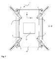
- FIG 7 shows the section B-B through the hood packaging installation 24 shown in Figure 6 , all four reefing fingers 2 and drive units 3 that are arranged on the reefing frame 26 being represented.
- the four reefing fingers 2 are moved by the respectively assigned drive unit 3 in the diagonal direction, as is indicated by the dash-dotted lines.
- the reefed portion of tubular film 4 (not represented here) is stretched in the X and Y directions.
- the reefing fingers 2 and drive units 3 may also be moved individually and separately from one another.
Landscapes
- Engineering & Computer Science (AREA)
- Mechanical Engineering (AREA)
- Containers And Plastic Fillers For Packaging (AREA)
- Basic Packing Technique (AREA)
Description
- The present invention concerns a reefing device with at least one reefing finger and at least one drive unit, which has an advancing means, which, for reefing a portion of tubular film, is brought into operative connection with the reefing finger, at least at the height of a point of engagement, while enclosing the portion of tubular film, and moves the portion of tubular film in relation to the reefing finger. The present invention also concerns a method for reefing a portion of tubular form with a reefing device according to the invention.
- Such reefing devices and methods are known per se e.g. from
US 4473990 , orEP 1574432 . Some, are used for example in hood packaging installations. These may be installations which operate on the basis of what is known as the hood stretching process or the hood shrinking process. Both processes are distinguished by the fact that a portion of a tubular film is pulled or pushed over any desired cargo, or that the cargo is introduced into the portion of tubular film by means of a lifting table. This is referred to hereafter as wrapping of cargo. The wrapping of the cargo with a portion of tubular film generally serves for the packaging and transportability of the cargo and for securing it during loading and protecting it from the effects of weather. To this extent, the portion of tubular film that is applied to the cargo may be designed not only as a hood but also, for example, as an upwardly open portion of tube in the manner of a banderole. - In the case of most hood packaging installations, the portion of tubular film is first reefed by means of a reefing device, to then be slipped over the cargo by the reefing device or by a separate drawing-over device and thereby unreefed. During the reefing, a supply of portions of tubular film laid in folds, which is also referred to hereafter as a film store, is formed at the bottom of the reefing fingers. If the reefing device is also used for the drawing over, the reefing device is moved in relation to the cargo, possibly after stretching the portion of tubular film. During this relative movement, the portion of tubular film is pulled off from the reefing fingers, also referred to as unreefed. Therefore, a film store is built up during the reefing, while the film store becomes depleted during the unreefing. To this extent, the expressions reefing, as reefing progresses, or the like, also refer to unreefing. For the reefing, the reefing fingers are usually introduced into the opened portion of tubular film from below, or the latter is lowered onto the reefing fingers. In order then to be able to move the portion of tubular film in relation to the reefing finger and lay it in folds, reefing devices of the generic type have at least one drive unit of any desired design, with an advancing means such as for instance a motor-operated conveyor belt or a reefing roller drive.
- For reefing the portion of tubular film, the drive unit is brought into operative connection with the reefing finger, at least at the height of a point of engagement, while enclosing the portion of tubular film. This may take place, for example, by pressing the drive device or the advancing means against the reefing finger at a single point. Then, by means of the drive unit or the advancing means, the portion of tubular film can be moved in relation to the reefing fingers under a certain pressing pressure and pushed onto or pulled off again from said fingers. There is therefore generally a frictional connection between the drive unit or the advancing means and the portion of tube. At least one point of engagement should be understood as meaning at least one location which comprises at least one point or a number of points, for example in the manner of a line or surface area.
- In order to achieve optimum wrapping of the cargo, uniform formation of folds that are as parallel as possible is advantageous. They should be produced during the reefing of the portion of film, and consequently during the building up of the film store. Non-uniform formation of folds has the consequence during the reefing of the portion of tubular film that the corresponding region of the portion of tubular film undergoes increased loading, since there is an abrupt pulling apart of the tubular film. It is not uncommon for this to lead to the portion of tubular film being pulled until thin, or even tearing, and consequently to reduced quality of the wrapping of the cargo.
- The invention is therefore based on the object of improving the reefing of a portion of tubular film, so that altogether improved quality of the wrapping of the cargo is obtained.
- The object is achieved by an device according to
claim 1 and by a method according to claim 10 Advantageous developments of the invention are described in the subclaims. - The reefing device according the invention differs from the reefing device described at the beginning in that the position of the at least one point of engagement can be changed along the reefing finger as reefing progresses. Unlike in the case of the previously known devices, the position of the point of engagement is adapted during the reefing to the extent of the film store. Consequently, a substantially constant distance can be maintained between the film store and the point of engagement, thereby bringing about always the same film formation during the reefing, and optimum unfolding during the unreefing of the portion of tubular film.
- If the film is acted upon at the height of different points of engagement, it is expedient if, with a number of points of engagement, the position of the lowermost point of engagement can be changed along the reefing finger as reefing progresses. The lowermost point of engagement should be understood here as meaning the point of engagement which is closest to the film store, or the bottom of the reefing finger. It is consequently possible for only the lowermost point of engagement to be changed in its position along the longitudinal axis of the reefing finger, while another point of engagement remains unchanged in its position. This has the advantage that the drive means can act on the portion of tubular film at a number of places, and consequently securely, with a relatively low structural expenditure. Nevertheless, the positive effect of uniform fold formation during the reefing and uniform unfolding during the unreefing is obtained on account of the distance from the film store being kept as constant as possible.
- In a development, at least one opposing roller is fastened to the reefing finger in such a way that the opposing roller can be brought into operative connection with the advancing means during the reefing, while enclosing the portion of tubular film, and defines the point of engagement. The opposing roller reduces the friction between the reefing finger and the tubular film.
- It is of advantage here of the at least one opposing roller is fastened to the reefing finger in such a way that the position of the opposing roller on the reefing finger can be changed as reefing progresses. Thus, in the case of a fixed advancing means, the point of engagement can be changed by changing the position of the opposing roller on the reefing finger.
- Expediently, the at least one opposing roller is fastened to the reefing finger in such a way that it is longitudinally and/or transversely displaceable and/or pivotable with respect to the reefing finger. A movement longitudinally with respect to the reefing finger can be understood here as meaning a movement along the longitudinal axis of the reefing finger. In this connection, a movement transverse to the reefing finger describes a movement transverse to the longitudinal axis of the reefing finger. This is of advantage since the movement of the opposing roller is accompanied by a corresponding change in position of the point of engagement. Accordingly, on the one hand a longitudinal displacement or corresponding pivoting of the opposing roller can define a point of engagement that is permanent but variable in its position with respect to the reefing finger. On the other hand, the point of engagement can be created and removed again as required by a transverse displacement or corresponding pivoting of the opposing roller. It is also conceivable that a point of engagement is first created for example by a transverse movement of the opposing roller and is then changed in its position with respect to the reefing finger by a longitudinal movement of the opposing roller, before the point of engagement is removed again by a renewed transverse movement.
- Advantageously, a plurality of opposing rollers are arranged on the reefing finger in such a way that different opposing rollers can be brought into operative connection with the advancing means as reefing progresses. Consequently, a plurality of points of engagement can be created, it being possible for the position of the lowermost point of engagement to be changed by the successive setting up and successive removal of the operative connections of individual opposing rollers to the advancing means.
- In a development, at least one fixedly mounted opposing roller may be arranged at the upper end of the reefing finger. This opposing roller serves firstly for securely guiding the portion of film over the upper end of the reefing finger. It may, however, also be used for creating a point of engagement in the sense of the invention, that is whenever the drive unit can be brought into operative connection with it. In this connection, the upper end of the reefing finger should be understood as meaning the end which is generally furthest away from the film store.
- Expediently, the drive unit and/or the advancing means can be at least partially changed in its/their position in relation to the reefing finger. Consequently, the position of a point of engagement can be changed by changing the position of the drive unit or the advancing means in relation to the reefing finger.
- In actual fact, the advancing means may be a drive roller or a continuous belt. However, it is also conceivable that the advancing means comprises a number of drive rollers, which can, for example, also be activated asynchronously. Expediently, the surface of the advancing means is profiled or coated in such a way that an ideal coefficient of friction is obtained for the advancement or movement of the portion of tubular film.
- In a development, the advancing means is pivotably and/or displaceably configured in such a way that, during the reefing, it can be brought into operative connection with the reefing finger, while enclosing the portion of tubular film, at different heights according to how much reefing has progressed. This has the advantage that the advancing means can be used to define at least one point of engagement, the position of which is changed by pivoting and/or displacing the advancing means. Consequently, the construction of the reefing finger can be kept relatively simple and does not have to be changed in comparison with conventional reefing fingers to realize the invention.
- Expediently, for this purpose the advancing means can be moved together with at least one opposing roller. In an expedient way, for this purpose the advancing means is pivotably and/or displaceably configured in such a way that, during the reefing, it is in operative connection with the at least one pivotable and/or displaceable opposing roller, while enclosing the portion of tubular film, according to how much reefing has progressed, while at least the position of the lowermost point of engagement is changed by displacing and pivoting the advancing means and the opposing roller. The at least one point of engagement is therefore defined both by the at least one opposing roller and by the advancing means and may be maintained on the film the whole time during reefing, while the position of the at least one point of engagement is changed. This allows there to be a distance between the lowermost point of engagement and the film store that is largely constant and as small as possible. In this way, an optimum reefing result can be achieved.
- Expediently, the advancing means is pivotably and/or displaceably configured in such a way that, during the reefing, it can be brought into operative connection with different opposing rollers, while enclosing the portion of tubular film, according to how much reefing has progressed. Consequently, the position particularly of the lowermost point of engagement can be changed intermittently, in that the advancing means is brought into operative connection with different opposing rollers one after the other.
- Furthermore, the reefing device may be designed in such a way that it comprises a plurality of reefing fingers and assigned drive units, it being possible for the individual reefing finger to be individually activated by its assigned drive unit. Thus, for example, four reefing fingers may be provided, with four respectively assigned drive units, which are respectively assigned to the corners of a typical packaging unit, such as for example a pallet. In the case of this design of the reefing device, the individual reefing fingers may be operated by their drive unit in isolation and separately from one another, for example if it is desired to achieve a specific fold formation, for instance to strengthen the package to be produced. The reefing operation may also be adapted to the respective circumstances, for example a more complex form of the cargo to be wrapped. If, for instance, an asymmetrical cargo has to be wrapped, it may be advantageous to reef a greater film store on one or more reefing fingers.
- As already mentioned, the object with respect to the method is achieved by a method for reefing a portion of tubular film according to
claim 14. The method according to the invention is therefore distinguished in comparison with known methods by the fact that the position of the lowermost point of engagement on the reefing finger is changed as reefing progresses. - Unlike before, the position of the point of engagement is adapted during the reefing to the extent of the film store. Consequently, the distance between the film store and the point of engagement can be kept substantially constant, whereby a more uniform fold formation during the reefing and a better unfolding of the film store during the unreefing of the portion of tubular film are obtained.
- Expediently, during the reefing of the portion of tubular film, the lowermost point of engagement is displaced from the lower end of the reefing finger to the upper end of the reefing finger. This provides a substantially constant and preferably minimal distance between the lowermost point of engagement and the film store, whereby a more uniform and constantly parallel formation of folds is achieved in the film store during the reefing of the portion of tubular film.
- Furthermore, it is expedient if, during the unreefing of the portion of tubular film, the lowermost point of engagement is displaced from the upper end of the reefing finger to the lower end of the reefing finger. The substantially constant and smallest possible distance between the lowermost point of engagement and the film store during the unreefing has the effect that the portion of tubular film is stripped off or unfolded from the reefing finger more uniformly than before. This too prevents the portion of tubular film from becoming thin or tearing as a result of the portion of tubular film being suddenly pulled apart.
- It is advantageous if the position of the lowermost point of engagement is changed by displacing and/or pivoting at least one opposing roller of the reefing finger. Thus, the movement of the at least one opposing roller can effect a corresponding change in position of the point of engagement. The longitudinal displacement or pivoting of the opposing roller may consequently define the point of engagement that is permanent but variable in its position with respect to the reefing finger, a transverse displacement or pivoting of the opposing roller creating or removing a point of engagement.
- It may also be advantageous if the position of the lowermost point of engagement is changed by displacing and/or pivoting the advancing means. Thus, the advantage of the constantly maintained distance of the point of engagement from the film store can be achieved with relatively little expenditure.
- The invention is explained in more detail below on the basis of exemplary embodiments that are shown the drawings, in which schematically:
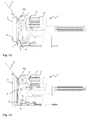
- Figures 1.1 to 1.5
- show a detail of the first exemplary embodiment of a reefing device according to the invention with an opposing roller that can be displaced transversely and longitudinally;
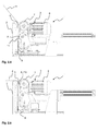
- Figures 2.1 to 2.6
- show a detail of a second exemplary embodiment of a reefing device according to the invention with two transversely displaceable opposing rollers;
- Figure 3
- shows the section A-A through the reefing device shown in
Figure 2 ; - Figure 4
- a side view of the lever mechanism shown in
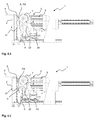
Figure 3 ; - Figures 5.1 to 5.5
- show a detail of a third exemplary embodiment of a third reefing device with advancing means;
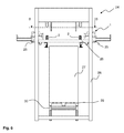
- Figure 6
- show a side view of a hood packaging installation with a reefing device according to the invention; and
- Figure 7
- the section B-B through the hood packaging installation shown in
Figure 6 . - The exemplary embodiments of a
reefing device 1 according to the invention that are shown inFigures 1 ,2 and5 each comprise a total of fourreefing fingers 2 that are arranged in the corners of a four-cornered reefing frame and can be individually activated, with in each case an assigneddrive unit 3 for reefing the portion oftubular film 4. For better representation of the invention, however, only onereefing finger 2 with its assigneddrive unit 3 is respectively shown inFigures 1 ,2 and5 . - In the case of all three embodiments shown here, the respectively L-shaped
reefing fingers 2 have a fixedly mounted opposingroller 5 at the upper end of the vertical member. On the horizontal members of thereefing fingers 2, adrive unit 3 is respectively displaceably arranged. Eachdrive unit 3 has areefing motor 6 and an advancingmeans 7, thereefing motor 6 driving the advancingmeans 7. In the case of all three exemplary embodiments shown here, the advancingmeans 7 is configured as a continuous belt, although it is also conceivable that it may be just a single roller or the like. Thedrive units 3 and the advancingmeans 7 thereof can be respectively displaced over guiding rails and thus brought into operative connection with the associatedreefing fingers 2. - In the case of the detail of a first exemplary embodiment of the reefing device according to the invention that is shown in
Figure 1 , apart from the fixedly but rotatably attached opposingroller 5, thereefing finger 2 has a further opposingroller 9, which is displaceable transversely and longitudinally with respect to thereefing finger 2. This opposing roller may be retracted completely into thereefing finger 2, as shown inFigure 1.1 , or be extended, as shown inFigure 1.2 . The pivoted-out opposingroller 9 therefore defines the lowermost point of engagement A here. - The method according to the invention for reefing a portion of
tubular film 4 according to a first embodiment is described below on the basis ofFigures 1.1 to 1.5 . -
Figure 1.1 shows thereefing device 1 in a method step in which a portion oftubular film 4 has already been pushed over thereefing finger 2 and, after that, the fourreefing fingers 2 have been spread slightly apart. Consequently, the opposingroller 5 that is fixedly mounted at the upper end of thereefing finger 2 is already in contact with the inner side of the portion oftubular film 4. Thedrive unit 3, however, has not yet been brought into operative connection with thereefing finger 2, while enclosing the portion oftubular film 4. - As shown in
Figure 1.2 , for this purpose thedrive unit 3 is moved horizontally. Then a first point of engagement, referred to hereafter as permanent point of engagement PA, is created at the opposingroller 5. At the same time, the opposingroller 9 is also extended. Therefore, here too, the advancingmeans 7 comes into operative connection with an opposing roller arranged on thereefing finger 2 and a second, lowermost point of engagement A is created, while enclosing the portion oftubular film 4. - Subsequently, as shown in
Figure 1.3 , the advancingmeans 7 is driven by means of thereefing motor 6, so that the portion oftubular film 4 is moved in relation to thereefing finger 2 and is consequently reefed. At the bottom of thereefing finger 2, the portion oftubular film 4 is laid down and forms thefilm store 8 there. As can be seen fromFigure 1.3 , thefilm store 8 increases as the reefing increasingly progresses, until the upper end of thefilm store 8 almost coincides spatially with the lowermost point of engagement A. - As can be seen from
Figure 1.4 , the displaceable opposingroller 9 is then displaced along the longitudinal axis of thereefing finger 2 in the direction of the upper end of thereefing finger 2, the distance between thefilm store 8 and the lowermost point of engagement A, defined with respect to the opposingroller 9, remaining substantially constant. As thefilm store 8 grows, the position of the lowermost point of engagement A is therefore likewise displaced in the direction of the upper end of thereefing finger 2. This provides consistent conditions under which the folds form and leads to a uniform formation of the folds in thefilm store 8. - As soon as the opposing
roller 9 has been displaced along thereefing finger 2 into its maximum, i.e. uppermost, position on thereefing finger 2, the opposingroller 9 is displaced or pivoted transversely with respect to the reefingfigure 2 , as represented inFigure 1.5 , and is consequently retracted into thereefing finger 2. This removes the operative connection between the opposingroller 9 and the advancingmeans 7. Consequently, the fixedly mounted opposingroller 5, which is still in operative connection with the advancingmeans 7, while enclosing the portion oftubular film 4, defines both the permanent point of engagement PA and the lowermost point of engagement A. At the same time, the reefing operation is ended, so that there is a sufficient distance between thefilm store 8 and the fixedly located opposingroller 5 to smooth the folds during the unreefing of the portion oftubular film 4 before they meet the opposingroller 5. - After ending the reefing operation, firstly part of the portion of
tubular film 4 is unreefed by a corresponding movement of the advancingmeans 7. Subsequently, the fourreefing devices 1 are moved apart and the portion oftubular film 4 is thereby stretched, as is indicated inFigure 1.5 by the unreefed part of the portion oftubular film 4 then extending horizontally with respect to thereefing finger 2. - The unreefing operation is not shown here, but proceeds substantially such that the opposing
roller 9 is only extended when the unreefing operation is well advanced - that is to say when thefilm store 8 has been depleted to the greatest extent - and can consequently be brought into operative connection with the advancingmeans 7, while enclosing the portion oftubular film 4. Furthermore, during the unreefing operation, thereefing motor 6 can drive the advancingmeans 7 in such a way that the unreefing speed of the portion oftubular film 4 thereby produced is slower than the relative speed of the reefing frame or thereefing device 1 with respect to the cargo to be wrapped. Consequently, during the unreefing, the portion oftubular film 4 is extended or stretched along the cargo in the direction of movement of the reefing frame. In order to prevent the portion oftubular film 4 being pulled thin or torn here during the stretching, an appropriate distance between the fixedly mounted opposingroller 5 and thefilm store 8 is necessary - as already described - for smoothing the folds. It is thus ensured that the portion oftubular film 4 completely unfolds before it meets the opposingroller 5. This ensures great immunity from tearing during unreefing.
If, during the unreefing, a deliberate, and consequently wanted, formation of folds is to be obtained in the tubular film, the movement of the reefing frame or thereefing device 1 may be interrupted at an appropriate point. The opposingroller 9 is brought into operative connection with the advancingmeans 7 at the desired height on thefilm store 8 and the corresponding part of thefilm store 8 is unreefed by driving of the advancingmeans 7. More film is thereby applied locally to the cargo to be wrapped, in order in this way to achieve a strengthening of the packaging. - In
Figure 2 , a detail of a second exemplary embodiment of thereefing device 1 according to the invention is shown. Unlike in the case of the first exemplary embodiment, arranged on thereefing finger 2 are twodisplaceable opposing rollers reefing finger 2, and a fixed opposingroller 5. - In the text which follows, the method according to the invention for reefing a portion of
tubular film 4 by using the previously described second embodiment of thereefing device 1 according to the invention is explained inFigures 2.1 to 2.6 . - In a way similar to that shown and explained in the case of the first embodiment in
Figure. 1.1 , first the portion oftubular film 4 is lowered onto the fourreefing fingers 2. Then, as shown inFigure 2.2 , at eachreefing finger 2 the assigneddrive unit 3 is brought into operative connection with thereefing finger 2. A permanent point of engagement PA is thereby created in the region of the fixedly mounted opposingroller 5 and the advancingmeans 7. Here, the portion oftubular film 4 is acted upon permanently and in the same position with respect to thereefing finger 2 during the reefing. At the same time, the two opposingrollers reefing finger 2. Therefore, two further points of engagement A and B are created. However, as will be shown below, unlike the point of engagement PA, these points of engagement are not present throughout the entire process. - And yet, first both opposing
rollers Figure 2.3 , the advancingmeans 7 is driven by means of thereefing motor 6. Consequently, the portion oftubular film 4 is laid in folds at the bottom of thereefing finger 2 and thefilm store 8 is produced or increased. As soon as the upper end of thefilm store 8 has almost reached the opposingroller 10, and consequently almost coincides spatially with the lowermost point of engagement A, the lowermost opposingroller 10 is displaced or retracted transversely with respect to thereefing finger 2. AsFigure 2.4 reveals, the operative connection to the lower opposingroller 10 is thereby removed. Consequently, the lowermost point of engagement A is then defined by the operative connection between the opposingroller 11 and the advancingmeans 7, while enclosing the portion oftubular film 4. With a growingfilm store 8, the position of the lowermost point of engagement A is consequently displaced in the direction of the upper end of thereefing finger 2 by retraction of the opposingroller 10. - When the upper end of the
film store 8 has then almost reached the opposingroller 11, the opposingroller 11 is also displaced transversely with respect to thereefing finger 2 and the operative connection in the region of the opposingroller 11 is removed. AsFigure 2.5 reveals, the fixedly mounted opposingroller 5 then defines both the permanent point of engagement PA and the lowermost point of engagement A at which the operative connection of the advancingmeans 7 and thereefing finger 2 exists, while enclosing the portion oftubular film 4. - During the subsequent unreefing of the portion of tubular film 4 - which proceeds in principle as already described in the case of the first exemplary embodiment - the opposing
rollers film store 8 is already depleted, that three points of engagement A, B, PA occur, as is shown inFigure 2.6 . -
Figure 3 shows the section A-A, through thereefing device 1 shown inFigure 2 , extending through thereefing finger 2. Thereefing finger 2 comprises alever mechanism 12 for pivoting the opposingrollers roller 5 within thereefing finger 2. -
Figure 4 shows thelever mechanism 12 according to the invention that is shown inFigure 3 in a representation on its own. The lower opposingroller 10 is arranged on thereefing finger 2 pivotably about afirst pivot axis 15 by means of afirst lever arm 13. The upper opposingroller 11 is arranged on thereefing finger 2 pivotably about asecond pivot axis 16 by means of asecond lever arm 14. The length of thelever arms rollers means 7. For the pivoting, thelever arms pneumatic cylinders lever arms spring springs lever arms rollers reefing finger 2 when thepneumatic cylinders - According to the invention, the
pneumatic cylinder rollers rollers lever mechanism 12 in thereefing finger 2 in a space-saving manner, thelever arms Figure 3 ). -
Figure 5 shows a detail of a third exemplary embodiment of areefing device 1 according to the invention, which in principle is constructed in a way similar to the two other exemplary embodiments. However, in this exemplary embodiment thereefing fingers 2 of thereefing device 1 have in addition to the opposingroller 5 fixedly mounted at the upper end of thereefing finger 2 in each case a further fixedly mounted opposingroller 21. Both opposingrollers means 7, while enclosing the portion oftubular film 4, by moving thedrive unit 3 or the advancingmeans 7 thereof. Thedrive unit 3 comprises apneumatic cylinder 22, which for this purpose can displace alower deflecting roller 23 of the advancingmeans 7 in a rail-guided manner. However, it is also conceivable that a hydraulic cylinder or the like is used instead of thepneumatic cylinder 22. - In the text which follows, the method according to the invention for reefing the portion of
tubular film 4 with the third embodiment of thereefing device 1 according to the invention is explained on the basis ofFigures 5.1 to 5.5 . - In the case of the method step shown in
Figure 5.1 , the portion oftubular films 4 has already been pushed over thereefing finger 2, and the fourreefing fingers 2 of thereefing device 1 have been slightly spread. The two fixedly mounted opposingrollers reefing fingers 2 is in contact with the inner side of the portion oftubular film 4. An operative connection between thedrive units 3 of thereefing fingers 2 has not yet been established. - Then, as shown in
Figure 5.2 , thedrive unit 3 is brought into operative connection with therespective reefing finger 2 while enclosing the portion oftubular film 4. The operative connection created between the upper opposingroller 5 and the advancingmeans 7, while enclosing thetubular film 4, defines a permanent point of engagement PA. The lowermost point of engagement A is created by pressing the advancingmeans 7, formed as a conveyor belt, against the lower opposingroller 21 of thereefing finger 2. - After that, the advancing
means 7 is driven by thereefing motor 6, and the reefing operation proceeds to the state represented inFigure 5.3 . The portion oftubular film 4 is hereby moved in relation to thereefing finger 2 and laid in folds at the bottom of thereefing finger 2. Thefilm store 8 produced increases as reefing progresses, until the upper end of thefilm store 8 has almost reached the opposingroller 21, as shown inFigure 5.3 . - As
Figure 5.4 reveals, a lower part of the advancingmeans 7, here thelower deflecting roller 23 of the conveyor belt, is then pushed away from the opposingroller 21 by actuation of thepneumatic cylinder 22. As a result, the operative connection of the lower opposingroller 21 and the advancingmeans 7 is removed. Consequently, only the upper opposingroller 5 is in operative connection with thedrive unit 3. The reefing can then be continued, but the reefing operation is ended in such a way that a sufficient distance remains between the producedfilm store 8 and the fixedly mounted opposingroller 5 for smoothing the folds during the unreefing of the portion oftubular film 4. The smoothing of the folds is also possible beyond the lower opposingroller 21, since this roller is not in operative connection with the advancingmeans 7. As described in the case of the first two exemplary embodiments, part of the portion oftubular film 4 is then unreefed again before the fourreefing fingers 2 of thereefing device 1 are moved apart, and the portion oftubular film 4 is consequently transversely extended, that is stretched. This state is shown inFigure 5.4 . - After the stretching, for the unreefing of the
film store 8, at first thelower deflecting roller 23 is still kept in the moved-out position shown inFigure 5.4 . However, once the film store has then been reduced to such an extent that it no longer reaches to the lower opposingroller 21, the lower deflecting roller of theconveyor belt 7 is moved up to the opposingroller 21, as shown inFigure 5.5 . Then, the remainingfilm store 8 is unreefed. - In this third exemplary embodiment too, during the unreefing operation the portion of
tubular film 4 can be stretched along the cargo to be wrapped by driving the advancingmeans 7, as described in the case of the other exemplary embodiments. Also in the case of this exemplary embodiment it is possible to apply the formation of folds specifically to the cargo to be wrapped, in order in this way to achieve a strengthening of the packaging. -
Figure 6 shows ahood packaging installation 24 operating on the basis of the stretching method, with thereefing device 1 according to the invention, thereefing device 1 comprising fourreefing fingers 2 with a respectively assigneddrive unit 3. Thereefing fingers 2 and the assigned drive units are fastened to a one-part reefing frame 26 byfastening plates 25. Since the representation inFigure 6 is a side view, only thereefing fingers 2 lying at the front are visible. Thedrive units 3 assigned to thereefing fingers 2 are concealed by the fastening plates 35. Thereefing fingers 2 can be moved in the horizontal direction for the stretching of the portion of tubular film 4 (not represented). For the wrapping of thecargo 27, after the reefing operation thereefing frame 26 is moved vertically along theframework 28. As this happens, the portion oftubular film 4 is unreefed from thereefing fingers 2 and thecargo 27 is packaged. Thecargo 27 is mounted on apallet 29 and is transported into and out of thehood packaging installation 24 by means of a transportingdevice 30. The transportingdevice 30 may, as shown here, be designed such that it is raised off the floor, so that thepallet 29 can be at least partially wrapped together with thecargo 27. -
Figure 7 shows the section B-B through thehood packaging installation 24 shown inFigure 6 , all fourreefing fingers 2 and driveunits 3 that are arranged on thereefing frame 26 being represented. For the stretching of the reefed portion oftubular film 4, the fourreefing fingers 2 are moved by the respectively assigneddrive unit 3 in the diagonal direction, as is indicated by the dash-dotted lines. As a result, the reefed portion of tubular film 4 (not represented here) is stretched in the X and Y directions. In order to be able to adapt the packaging to be achieved individually to therespective cargo 27, thereefing fingers 2 and driveunits 3 may also be moved individually and separately from one another. -
- 1
- Reefing device
- 2
- Reefing finger
- 3
- Drive unit
- 4
- Portion of tubular film
- 5
- Fixedly mounted opposing roller
- 6
- Reefing motor
- 7
- Advancing means
- 8
- Film store
- 9
- Transversely and longitudinal a displaceable opposing roller
- 10
- Transversely displaceable opposing roller
- 11
- Transversely displaceable opposing roller
- 12
- Lever mechanism
- 13
- First lever arm
- 14
- Second lever arm
- 15
- First pivot axis
- 16
- Second pivot axis
- 17
- First pneumatic cylinder
- 18
- Second pneumatic cylinder
- 19
- Spring
- 20
- Spring
- 21
- Fixedly mounted opposing roller
- 22
- Pneumatic cylinder
- 23
- Lower deflecting roller of the advancing means
- 24
- Hood packaging installation
- 25
- Fastening plate
- 26
- Reefing frame
- 27
- Cargo
- 28
- Framework
- 29
- Pallet
- 30
- Transporting device
- A
- lowermost point of engagement
- B
- further point of engagement
- PA
- permanent point of engagement
Claims (14)
- A reefing device (1) with at least one reefing finger (2) and at least one drive unit (3), which has an advancing means (7), which, for reefing a portion of tubular film (4), is brought into operative connection with the reefing finger (2), at least at the height of a point of engagement (A), while enclosing the portion of tubular film (4), and moves the portion of tubular flm (4) in relation to the reefing finger (2),
characterized in that
at least one opposing roller (5, 9, 10, 11, 12) is arranged on the reefing finger (2) in such a way that it can be brought into operative connection with the advancing means (7) during the reefing, while enclosing the portion of tubular film (4), and defines the point of engagement (A, B, PA), wherein
the at least one opposing roller (9, 10, 11) is fastened to the reefing finger (2) in such a way that it is longitudinally and/or transversely displaceable and/or pivotable with respect to the reefing finger (2) and the position of the at least one point of engagement (A) is changed along the reefing finger (2) as reefing progresses. - The device as claimed in claim 1,
characterized in that
in the case of a number of points of engagement (A, B, PA), at least the position of the lowermost point of engagement (A) is changed along the reefing finger (2) as reefing progresses. - The device as claimed in one of the preceding claims,
characterized in that
a plurality of opposing rollers (9, 10, 11, 12) are arranged on the reefing finger (2) in such a way that different opposing rollers (9,10, 11,12) can be brought into operative connection with the advancing means (7) as reefing progresses. - The device as claimed in one of the preceding claims,
characterized in that
at least one fixedly mounted opposing roller (5) is arranged at the upper end of the reefing finger (2). - The device as claimed in one of the preceding claims,
characterized in that
the drive unit (3) and/or the advancing means (7) is at least partially changed in its/their position in relation to the reefing finger (2). - The device as claimed in one of the preceding claims,
characterized in that
the advancing means (7) is a drive roller or a continuous belt. - The device as claimed in one of the preceding claims,
characterized in that
the advancing means (7) is pivotably and/or displaceably configured in such a way that, during the reefing, it is in operative connection with a pivotable and/or displaceable opposing roller, while enclosing the portion of tubular film (4), according to how much reefing has progressed, while the position of the lowermost point of engagement is changed by displacing and pivoting the advancing means (7) and/or the opposing roller. - The device as claimed in one of the preceding claims,
characterized in that
the advancing means is pivotably and/or displaceably configured in such a way that, during the reefing, it can be brought into operative connection with different opposing rollers (5, 12), while enclosing the portion of tubular film (4), according to how much reefing has progressed. - The device as claimed in one of the preceding claims,
characterized in that
the reefing device (1) comprises a plurality of reefing fingers (2) and assigned drive units (3), it being possible for the individual reefing finger (2) to be individually activated by its assigned drive unit (3). - A method for reefing a portion of tubular film (4) with a reefing device (1) as claimed in one of the preceding claims,
characterized in that
the position of the lowermost point of engagement (A) on the reefing finger (2) is changed as reefing progresses. - The method as claimed in claim 10,
characterized in that
during the reefing of the portion of tubular film (4), the lowermost point of engagement (A) is displaced from the lower end of the reefing finger (2) to the upper end of the reefing finger (2). - The method as claimed in claim 10 or 11,
characterized in that
during the unreefing of the portion of tubular film (4), the lowermost point of engagement (A) is displaced from the upper end of the reefing finger (2) to the lower end of the reefing finger (2). - The method as claimed in one of the preceding claims,
characterized in that
the position of the lowermost point of engagement (A) is changed by displacing and/or pivoting at least one opposing roller (9, 10, 11) of the reefing finger (2). - The method as claimed in one of the preceding claims,
characterized in that
the position of the lowermost point of engagement (A) is changed by displacing and/or pivoting the advancing means (7).
Applications Claiming Priority (2)
| Application Number | Priority Date | Filing Date | Title |
|---|---|---|---|
| DE102011000205.7A DE102011000205B4 (en) | 2011-01-18 | 2011-01-18 | Apparatus and method for reefing a tubular film section |
| PCT/US2012/021646 WO2012099918A1 (en) | 2011-01-18 | 2012-01-18 | Reefing device |
Publications (2)
| Publication Number | Publication Date |
|---|---|
| EP2665652A1 EP2665652A1 (en) | 2013-11-27 |
| EP2665652B1 true EP2665652B1 (en) | 2016-08-24 |
Family
ID=45554883
Family Applications (1)
| Application Number | Title | Priority Date | Filing Date |
|---|---|---|---|
| EP12701635.0A Active EP2665652B1 (en) | 2011-01-18 | 2012-01-18 | Reefing device |
Country Status (7)
| Country | Link |
|---|---|
| US (2) | US9764867B2 (en) |
| EP (1) | EP2665652B1 (en) |
| DE (1) | DE102011000205B4 (en) |
| DK (1) | DK2665652T3 (en) |
| ES (1) | ES2605108T3 (en) |
| PL (1) | PL2665652T3 (en) |
| WO (1) | WO2012099918A1 (en) |
Families Citing this family (18)
| Publication number | Priority date | Publication date | Assignee | Title |
|---|---|---|---|---|
| DE102011000205B4 (en) | 2011-01-18 | 2014-07-17 | Illinois Tool Works Inc. | Apparatus and method for reefing a tubular film section |
| DE102011075451B4 (en) | 2011-05-06 | 2014-05-08 | Illinois Tool Works Inc. | Method and device for impinging a tubular film section on the refining fingers of a packaging installation |
| FI124180B (en) | 2011-09-30 | 2014-04-15 | Illinois Tool Works | Method of bringing a winding machine into a transport position and winding machine |
| US10440432B2 (en) * | 2012-06-12 | 2019-10-08 | Realnetworks, Inc. | Socially annotated presentation systems and methods |
| FI125661B (en) | 2012-09-07 | 2015-12-31 | Signode Int Ip Holdings Llc | Method and apparatus for attaching corner guard to a load |
| FI125411B (en) | 2013-10-31 | 2015-10-15 | Signode Internat Ip Holdings Llc | Method and fasteners for securing the end of a wrapping film web to a packaging machine and packaging machine |
| DE102014106365B4 (en) | 2014-05-07 | 2017-06-14 | Lachenmeier Aps | Packaging process for packaging a good |
| WO2015195907A1 (en) * | 2014-06-18 | 2015-12-23 | Sharp Packaging Systems, Llc | Bagging machine and method |
| DK178374B1 (en) | 2014-11-04 | 2016-01-18 | Frank Bruhn Aps | HORIZONTALLY ARRANGED WRAP PACKAGING SYSTEM |
| DE102015101489A1 (en) | 2015-02-02 | 2016-08-04 | Signode Industrial Group Llc | Packaging device and method of operating the same |
| ITUB20159526A1 (en) * | 2015-12-18 | 2017-06-18 | Messersi Packaging Srl | MOLDING MACHINE |
| DE102016212436B4 (en) * | 2016-07-07 | 2018-07-26 | Signode Industrial Group Llc | Packaging process and hood stretcher |
| US10313751B2 (en) * | 2016-09-29 | 2019-06-04 | International Business Machines Corporation | Digital display viewer based on location |
| DE102019216346A1 (en) * | 2019-10-23 | 2021-04-29 | Signode Industrial Group Llc | Method and device for packaging a stack of goods in a tubular stretch film |
| US11492155B2 (en) * | 2020-05-14 | 2022-11-08 | Signode Industrial Group Llc | Stretch-hood machine |
| KR20250086725A (en) * | 2022-11-30 | 2025-06-13 | 시그노드 인더스트리얼 그룹 엘엘씨 | Stretch hood machine with perforator |
| WO2025165845A1 (en) * | 2024-02-01 | 2025-08-07 | Signode Industrial Group Llc | Stretch-hood machine with retractable counter rollers |
| EP4631869A1 (en) * | 2024-04-10 | 2025-10-15 | Officina Meccanica Sestese S.p.A. | Accumulative hodding apparatus and relative hodding method |
Family Cites Families (103)
| Publication number | Priority date | Publication date | Assignee | Title |
|---|---|---|---|---|
| US2745688A (en) | 1951-02-27 | 1956-05-15 | Thompson Electric Company | Solid adjustable angle fitting |
| US2711803A (en) | 1952-02-05 | 1955-06-28 | Mccabe Powers Auto Body Co | Folding lifting booms |
| US2758898A (en) | 1953-03-09 | 1956-08-14 | Kobsch Karl | Dropleaf extension table |
| US2797634A (en) | 1955-04-19 | 1957-07-02 | Swift & Co | Packaging |
| US2942797A (en) | 1957-11-14 | 1960-06-28 | Western Electric Co | Apparatus for handling spools of wire while the wire is being withdrawn therefrom |
| US3016869A (en) | 1961-01-23 | 1962-01-16 | Mcculloch Corp | Outboard motor tilt mechanism |
| US3190457A (en) | 1962-06-25 | 1965-06-22 | Linden Knut Elis | Mobile crane with pivotable boom mounted for alternate use as a tower |
| FR1396355A (en) | 1963-12-24 | 1965-04-23 | Operating unit with gear change by interchangeable gear trains | |
| US3278059A (en) | 1964-11-16 | 1966-10-11 | Edward L Ridgeway | Lift and dump apparatus for refuse containers |
| US3436046A (en) | 1967-09-01 | 1969-04-01 | Ritter Pfaudler Corp | Infinite positioning mechanism for a movable arm |
| US3507137A (en) | 1968-03-01 | 1970-04-21 | Westinghouse Electric Corp | Winding machine |
| US3626654A (en) | 1968-04-17 | 1971-12-14 | Reynolds Metals Co | Method of overwrapping a package |
| US3852937A (en) * | 1968-08-06 | 1974-12-10 | Auburn Eng Inc | Shrink-wrapping method and apparatus |
| US3679244A (en) | 1970-09-21 | 1972-07-25 | Robert R Reddy | Releasable shaft lock |
| DE2256753A1 (en) | 1972-11-15 | 1974-05-22 | Hirschfeld Martin Dr Ing | MACHINE-RELATED, INTERCHANGEABLE HOUSING BOXES FOR REPLACEMENT WHEEL TRANSMISSION GROUPS |
| US3944045A (en) | 1973-08-31 | 1976-03-16 | Comptex, Inc. | Device for centering a load in a bagging machine |
| US4204377A (en) | 1974-06-12 | 1980-05-27 | Lantech, Inc. | Process and apparatus for wrapping netting material around a load |
| US3902303A (en) * | 1974-08-19 | 1975-09-02 | Henry E King | Stretch bag wrapping machine |
| US4063401A (en) * | 1974-09-24 | 1977-12-20 | Higgins David M | Bagging machine |
| US4067174A (en) | 1976-12-20 | 1978-01-10 | Joseph Goldstein | Stretch wrap machine |
| US4235062A (en) | 1978-07-26 | 1980-11-25 | Lantech Inc. | Collapsible web wrapping apparatus |
| FR2473985A1 (en) * | 1980-01-17 | 1981-07-24 | Thimon | MACHINE FOR PACKING A LOAD IN A SHEET STRING IN A FLEXIBLE MATERIAL |
| AU537995B2 (en) | 1980-01-30 | 1984-07-26 | Mitsubishi Rayon Company Limited | Graft polymerisation process |
| US5195297A (en) | 1980-02-27 | 1993-03-23 | Lantech, Inc. | Unitized display packages and method and apparatus for utilizing display packages |
| US4754594A (en) | 1980-02-27 | 1988-07-05 | Lantech, Inc. | Z-stretch wrapping system |
| US4317322A (en) | 1980-05-20 | 1982-03-02 | Lantech, Inc. | Rotatable film wrapping apparatus with wrap carrying mechanism |
| US4588142A (en) | 1981-07-20 | 1986-05-13 | Malzacher Fred H | Cable spooling system |
| US4587796B1 (en) | 1983-04-21 | 1997-12-23 | Newtec Int | Packaging machine |
| IT1172435B (en) | 1983-11-16 | 1987-06-18 | Dario Manuli Spa | EQUIPMENT FOR WINDING A PALLETIZED LOAD CONTINUOUSLY |
| US4619193A (en) | 1985-03-29 | 1986-10-28 | Crew Gerald W | Standing tree baler |
| US4756143A (en) | 1987-02-26 | 1988-07-12 | Lantech, Inc. | Lower guided lower driven wrapping device |
| FI78433C (en) | 1987-05-27 | 1989-08-10 | Haloila M Oy Ab | Device and method for replacing the film roll by winding |
| US4905448A (en) | 1987-05-29 | 1990-03-06 | Wrapmatic, Inc. | Overhead stretch film wrap machines, including overhead stretch film wrap machines with film pre-stretch devices |
| FR2617123B1 (en) | 1987-06-26 | 1989-12-29 | Newtec Int | TAPE WITH LONGITUDINAL REINFORCEMENT, PACKAGING METHOD AND PACKAGING COMPRISING SUCH A TAPE, INSTALLATION AND MACHINE FOR CARRYING OUT THE PACKAGING PROCESS, AND DEVICE FOR CARRYING OUT SUCH A TAPE |
| DE58900904D1 (en) | 1988-06-03 | 1992-04-09 | Beumer Maschf Bernhard | METHOD AND DEVICE FOR COVERING PIECES OF GOODS, IN PARTICULAR STACKS OF GOODS, WITH A STRETCH FILM HOOD. |
| US4939989A (en) | 1989-03-02 | 1990-07-10 | Donald Zacharias | Tree limb folding and tying apparatus |
| DE3914595A1 (en) | 1989-05-03 | 1990-11-08 | Sengewald Karl H Gmbh | Foil bag with opening fold - has weakened line in triple fold area to be covered once opened |
| JP2694392B2 (en) | 1991-03-26 | 1997-12-24 | 株式会社田村電機製作所 | Reader |
| DE4113281A1 (en) | 1991-04-24 | 1992-10-29 | Hannen Reiner Develog | METHOD FOR WINDING A PALLETED GOODS STACK WITH A STRETCH FILM AND DEVICE FOR CARRYING OUT THE METHOD |
| US5107657A (en) | 1991-04-30 | 1992-04-28 | Mima Incorporated | Wrapping apparatus and related wrapping methods |
| US5140795A (en) | 1991-05-30 | 1992-08-25 | Sds, Inc. | Apparatus for securing objects to a storage pallet and wrapping arm mechanism therefor |
| FI91624C (en) | 1992-10-05 | 1995-05-03 | Haloila M Oy Ab | Apparatus for joining and cutting a wrapping film |
| EP0666814A1 (en) | 1992-11-09 | 1995-08-16 | James River Corporation Of Virginia | Bulk package wrapping and securing system |
| US5414979A (en) | 1993-04-23 | 1995-05-16 | Lantech, Inc. | Stretch wrapping apparatus |
| SE502041C2 (en) | 1993-11-17 | 1995-07-24 | Burtech Ab | Stepwise variable transmission between stretch rollers in a stretch film machine |
| US5596863A (en) | 1995-06-12 | 1997-01-28 | Illinois Tool Works Inc. | Method and apparatus for applying edge protectors |
| US5623808A (en) | 1996-01-19 | 1997-04-29 | Hk Systems, Inc. | Apparatus and method for palletizing and wrapping a load |
| US5768862A (en) | 1996-05-06 | 1998-06-23 | Robopac Sistemi S.R.L. | Apparatus for the wrapping of palletized product groups with plastic film |
| DE19732298C1 (en) * | 1997-07-26 | 1999-02-04 | Moellers Maschf Gmbh | Machine for covering stacked articles with film packaging |
| US6293074B1 (en) | 1998-02-20 | 2001-09-25 | Lantech Management Corp. | Method and apparatus for stretch wrapping a load |
| DE59811838D1 (en) | 1998-11-05 | 2004-09-23 | Lachenmeier Kurt Aps | Method and device for attaching and shrinking a packaging hood onto an object |
| US6178721B1 (en) | 1999-03-04 | 2001-01-30 | Illinois Tool Works Inc. | Apparatus and method for placing corner protectors of different heights on palletized |
| EP1059233A1 (en) * | 1999-04-16 | 2000-12-13 | Kl- Lachenmeier A/S | Method and device for packaging objects in a film-hood |
| US6237307B1 (en) | 1999-11-02 | 2001-05-29 | Illinois Tool Works Inc. | Apparatus and method for manually applying stretch film to palletized products |
| IT1311134B1 (en) | 1999-11-05 | 2002-03-04 | Aetna Group Spa | EQUIPMENT FOR THE AUTOMATIC CHANGE OF FILM REELS. |
| DE60002028T2 (en) | 1999-12-13 | 2003-10-16 | Norgren Automotive Inc., Mt. Clemens | Modular tool coupling device |
| US20010046409A1 (en) | 2000-02-18 | 2001-11-29 | Fischer Roy K. | Connector assembly |
| DK1184281T3 (en) * | 2000-08-09 | 2003-07-14 | Lachenmeier As | Method and device for packaging articles |
| FI20001779L (en) | 2000-08-10 | 2002-02-11 | United Packaging Plc | Method and device for improving the efficiency of a wrapping packaging machine |
| JP2002104308A (en) | 2000-09-22 | 2002-04-10 | Tokyo Autom Mach Works Ltd | Automatic opening-position setting device of lateral sealer in bag-making/filling/packaging machine |
| DE20101909U1 (en) | 2001-01-25 | 2002-06-13 | MSK-Verpackungs-Systeme GmbH, 47533 Kleve | Device for wrapping a stack of goods |
| US6666133B2 (en) | 2001-04-11 | 2003-12-23 | Lee W. Squyres | Standing tree baler |
| EP1266828B1 (en) | 2001-06-13 | 2005-05-04 | Beumer Maschinenfabrik GmbH & Co. KG | Method and apparatus for wrapping stacks of articles in a stretchable foil cover or sleeve |
| US6539690B2 (en) | 2001-06-27 | 2003-04-01 | Illinois Tool Works Inc. | Semi-automatic film cut/clamp device and method of operating the same |
| TW530961U (en) | 2002-02-20 | 2003-05-01 | Hannstar Display Corp | Stepwise pivot mechanism |
| DK1497176T3 (en) | 2002-04-19 | 2008-03-25 | Msk Verpackung Syst Gmbh | Apparatus and method for packaging unit or package goods |
| US6622620B1 (en) | 2002-08-05 | 2003-09-23 | Shain Byington | Tree compression and binding apparatus |
| IES20020874A2 (en) | 2002-11-11 | 2004-05-19 | Arboc Ltd | A pre-stretching device |
| WO2004045952A1 (en) | 2002-11-21 | 2004-06-03 | Machinery Developments Limited | Bagging apparatus, method of bagging and processing line |
| FI115394B (en) | 2003-02-27 | 2005-04-29 | Haloila M Oy Ab | Wrapping machine, coating film machine and method for storing and / or transporting the wrapping machine and / or coating film machine |
| US7367740B2 (en) | 2003-04-10 | 2008-05-06 | Pedrag Lazic | Mechanically lockable universal joint and structures employing such joint |
| FI125041B (en) | 2003-04-22 | 2015-05-15 | Signode Internat Ip Holdings Llc | Wrapping machine and method of wrapping a plastic wrap web around a product |
| FR2863755B1 (en) | 2003-12-10 | 2006-10-27 | Sagem | METHOD AND SYSTEM FOR IDENTIFYING A MOVING VEHICLE |
| PT1574432E (en) | 2004-03-09 | 2007-08-31 | Lachenmeier As | DOUBLE CONTACT FOLDING SYSTEM. |
| US20060040085A1 (en) | 2004-08-17 | 2006-02-23 | Downs John P | Adhesive segment applicator method and apparatus and roll of adhesive segments for use therewith |
| DE102005037916B4 (en) | 2004-11-11 | 2018-08-02 | Windmöller & Hölscher Kg | Machine for forming, filling and closing sacks and method of operating same |
| US7707801B2 (en) | 2005-04-08 | 2010-05-04 | Lantech.Com, Llc | Method for dispensing a predetermined amount of film relative to load girth |
| US20060285915A1 (en) | 2005-06-01 | 2006-12-21 | Norgren Automotive, Inc. | Apparatus for incrementally adjusting a modular tooling coupling |
| US20060272286A1 (en) | 2005-06-02 | 2006-12-07 | Tuan-Mei Chiu Chen | Adhesive tape applying machine for use with a stretch wrapper |
| WO2007056377A1 (en) | 2005-11-07 | 2007-05-18 | Lantech.Com, Llc | Method and apparatus for securing a final tail of film to a load wrapped with this film |
| FR2893005A1 (en) | 2005-11-10 | 2007-05-11 | Thimon Sa | METHOD AND MACHINE FOR PREPARING AND REMOVING A PACKAGING SLEEVE FROM A PALLETIZED LOAD |
| DE102005062609A1 (en) | 2005-12-23 | 2007-07-05 | Lachenmeier A/S | Method for packing articles e.g. palleted stack of goods with a film hood, involves folding flat hose in v-shape, after final removal from supply and before closing outer sides |
| WO2008031449A1 (en) | 2006-09-15 | 2008-03-20 | Lachenmeier A/S | Packaging apparatus, locking mechanism for a packaging apparatus, and method for operating the former |
| WO2008040110A1 (en) | 2006-10-06 | 2008-04-10 | Mark Bernard Fitzpatrick | Bag holder |
| DE102007033830A1 (en) | 2007-07-18 | 2009-01-22 | Packtron Gmbh | Method for packaging packaged goods and apparatus for carrying out this method |
| US7987651B2 (en) | 2007-09-17 | 2011-08-02 | Lummus Corporation | Automatic bale wrapping apparatus |
| CN101801828B (en) | 2007-09-17 | 2013-05-22 | 3M创新有限公司 | Linered tape applicator |
| EP2060493B1 (en) | 2007-11-13 | 2010-06-23 | Oy M. Haloila Ab | Film delivery device and use of same |
| EP2060492B1 (en) * | 2007-11-16 | 2011-11-30 | Msk-Verpackungs-Systeme Gesellschaft Mit Beschränkter Haftung | Device for drawing a tubular film or a film cover over a stack |
| DE202007018900U1 (en) * | 2007-11-16 | 2009-08-27 | Msk - Verpackungs-Systeme Gmbh | Device for coating a tubular film or a film hood over a stack of goods |
| US7908831B1 (en) | 2007-11-27 | 2011-03-22 | Dugan Michael E | Stretch wrap rope converter and wrapping system |
| US7707802B2 (en) | 2008-02-29 | 2010-05-04 | Illinois Tool Works Inc. | Film roping assembly for use within film wrapping or packaging machines |
| MX2010013053A (en) | 2008-05-29 | 2011-07-29 | Atlantic Corp | Systems for monitoring and controlling usage of materials. |
| US9676507B2 (en) | 2008-07-23 | 2017-06-13 | Best Packaging, Inc. | Stretch wrapping system and process |
| EP2371716B1 (en) | 2008-12-19 | 2012-06-13 | MSK - Verpackungs-Systeme GmbH | Method and device for drawing a tubular film or a film cover over a stack |
| US8453420B2 (en) | 2009-05-29 | 2013-06-04 | Illinois Tool Works Inc. | Film dispensing and wrapping apparatus or system using smart technology |
| US8347784B2 (en) | 2010-03-24 | 2013-01-08 | Herrmann Douglas S | Standing tree baler |
| CN101830292B (en) | 2010-04-28 | 2011-09-07 | 哈尔滨博实自动化股份有限公司 | Tubular membrane reeling, unreeling and stretching mechanism |
| EP2608953B1 (en) | 2010-08-26 | 2015-05-13 | Mollers North America, Inc. | Corner post application system |
| DE102010037770B4 (en) | 2010-09-24 | 2012-06-14 | Illinois Tool Works Inc. | Method and device for at least partially wrapping a stack of pieces with a hose section |
| DE102011000205B4 (en) | 2011-01-18 | 2014-07-17 | Illinois Tool Works Inc. | Apparatus and method for reefing a tubular film section |
| JP2013154956A (en) | 2012-01-30 | 2013-08-15 | Mito Saien Corp | Four-sided 3d package and four-sided 3d packaging method |
| DE102012024176B4 (en) | 2012-12-10 | 2019-02-07 | Beumer Gmbh & Co. Kg | Device for coating a tubular packaging film and reef element |
-
2011
- 2011-01-18 DE DE102011000205.7A patent/DE102011000205B4/en not_active Expired - Fee Related
-
2012
- 2012-01-18 DK DK12701635.0T patent/DK2665652T3/en active
- 2012-01-18 WO PCT/US2012/021646 patent/WO2012099918A1/en not_active Ceased
- 2012-01-18 EP EP12701635.0A patent/EP2665652B1/en active Active
- 2012-01-18 ES ES12701635.0T patent/ES2605108T3/en active Active
- 2012-01-18 US US13/980,136 patent/US9764867B2/en active Active
- 2012-01-18 PL PL12701635T patent/PL2665652T3/en unknown
-
2017
- 2017-09-18 US US15/707,617 patent/US10093439B2/en active Active
Also Published As
| Publication number | Publication date |
|---|---|
| US20140013714A1 (en) | 2014-01-16 |
| DE102011000205A1 (en) | 2012-07-19 |
| EP2665652A1 (en) | 2013-11-27 |
| DK2665652T3 (en) | 2016-12-19 |
| PL2665652T3 (en) | 2017-02-28 |
| US10093439B2 (en) | 2018-10-09 |
| US9764867B2 (en) | 2017-09-19 |
| ES2605108T3 (en) | 2017-03-13 |
| US20180065766A1 (en) | 2018-03-08 |
| WO2012099918A1 (en) | 2012-07-26 |
| DE102011000205B4 (en) | 2014-07-17 |
Similar Documents
| Publication | Publication Date | Title |
|---|---|---|
| US10093439B2 (en) | Gripper | |
| US5077956A (en) | Method for banding a palletized load | |
| US9290285B2 (en) | Film clamp and related methods and apparatuses for wrapping loads | |
| CN113371241A (en) | Automatic film roll packaging device and packaging method thereof | |
| EP2704947B1 (en) | Reefing under stretch | |
| CN206232130U (en) | Tablet separator | |
| JP2002535207A (en) | Device for inserting objects, especially blister strips, into folding boxes | |
| US7234289B2 (en) | Method of fitting a packaging hood over a load | |
| EP1426296B1 (en) | Apparatus for the fastening of the tail of wrappings of stretchable film for palletized goods | |
| CN103241400A (en) | Shrink packing system | |
| CN116280392A (en) | An integrated device for automatic film wrapping and bottom care of glass fiber yarn rolls | |
| ITBO990560A1 (en) | DEVICE FOR THE AUTOMATIC REPLACEMENT OF THE SHEET FEEDING COIL WITH WHICH THE MATTRESSES ARE WRAPPED AND SIMILAR IN MACHINES WITH | |
| RS62153B1 (en) | Wrapping machine | |
| CN113291526A (en) | Full-automatic packaging equipment and method for ceramic tiles | |
| ITMI20121690A1 (en) | PACKAGING PACKING MACHINE PERFECTED, WITH ADJUSTMENT IN THE HEIGHT OF THE DISTRIBUTION DEVICE. | |
| KR20100108134A (en) | Strips for cable tie of manufacturing apparatus | |
| CN216943710U (en) | Plastic bag handle folding device | |
| CN113479381B (en) | Net packing system and method | |
| JPH0710284A (en) | Device for automatically stacking up channel steel | |
| EP1012085B1 (en) | Apparatus for loading and unloading leathers, skins or similars, on or from, airchain conveyors | |
| CN107777370A (en) | Tablet separation equipment | |
| CN210362697U (en) | Full-automatic high-speed bagging device | |
| ITBO990236A1 (en) | PANEL COLLECTION AND FEEDING SYSTEM. | |
| US7089716B2 (en) | Apparatus for forming and packaging flexible ducting | |
| CN113802362A (en) | Cloth cutting machine |
Legal Events
| Date | Code | Title | Description |
|---|---|---|---|
| PUAI | Public reference made under article 153(3) epc to a published international application that has entered the european phase |
Free format text: ORIGINAL CODE: 0009012 |
|
| 17P | Request for examination filed |
Effective date: 20130718 |
|
| AK | Designated contracting states |
Kind code of ref document: A1 Designated state(s): AL AT BE BG CH CY CZ DE DK EE ES FI FR GB GR HR HU IE IS IT LI LT LU LV MC MK MT NL NO PL PT RO RS SE SI SK SM TR |
|
| RAP1 | Party data changed (applicant data changed or rights of an application transferred) |
Owner name: ILLINOIS TOOL WORKS INC. |
|
| DAX | Request for extension of the european patent (deleted) | ||
| RAP1 | Party data changed (applicant data changed or rights of an application transferred) |
Owner name: PREMARK PACKAGING LLC |
|
| RAP1 | Party data changed (applicant data changed or rights of an application transferred) |
Owner name: SIGNODE INTERNATIONAL IP HOLDINGS LLC |
|
| 17Q | First examination report despatched |
Effective date: 20150408 |
|
| GRAP | Despatch of communication of intention to grant a patent |
Free format text: ORIGINAL CODE: EPIDOSNIGR1 |
|
| INTG | Intention to grant announced |
Effective date: 20160229 |
|
| GRAS | Grant fee paid |
Free format text: ORIGINAL CODE: EPIDOSNIGR3 |
|
| GRAA | (expected) grant |
Free format text: ORIGINAL CODE: 0009210 |
|
| AK | Designated contracting states |
Kind code of ref document: B1 Designated state(s): AL AT BE BG CH CY CZ DE DK EE ES FI FR GB GR HR HU IE IS IT LI LT LU LV MC MK MT NL NO PL PT RO RS SE SI SK SM TR |
|
| REG | Reference to a national code |
Ref country code: GB Ref legal event code: FG4D |
|
| REG | Reference to a national code |
Ref country code: CH Ref legal event code: EP |
|
| REG | Reference to a national code |
Ref country code: AT Ref legal event code: REF Ref document number: 822818 Country of ref document: AT Kind code of ref document: T Effective date: 20160915 |
|
| REG | Reference to a national code |
Ref country code: IE Ref legal event code: FG4D |
|
| REG | Reference to a national code |
Ref country code: DE Ref legal event code: R096 Ref document number: 602012022151 Country of ref document: DE |
|
| REG | Reference to a national code |
Ref country code: NL Ref legal event code: FP |
|
| REG | Reference to a national code |
Ref country code: SE Ref legal event code: TRGR |
|
| REG | Reference to a national code |
Ref country code: DK Ref legal event code: T3 Effective date: 20161216 |
|
| REG | Reference to a national code |
Ref country code: LT Ref legal event code: MG4D |
|
| REG | Reference to a national code |
Ref country code: AT Ref legal event code: MK05 Ref document number: 822818 Country of ref document: AT Kind code of ref document: T Effective date: 20160824 |
|
| REG | Reference to a national code |
Ref country code: FR Ref legal event code: PLFP Year of fee payment: 6 |
|
| PG25 | Lapsed in a contracting state [announced via postgrant information from national office to epo] |
Ref country code: RS Free format text: LAPSE BECAUSE OF FAILURE TO SUBMIT A TRANSLATION OF THE DESCRIPTION OR TO PAY THE FEE WITHIN THE PRESCRIBED TIME-LIMIT Effective date: 20160824 Ref country code: NO Free format text: LAPSE BECAUSE OF FAILURE TO SUBMIT A TRANSLATION OF THE DESCRIPTION OR TO PAY THE FEE WITHIN THE PRESCRIBED TIME-LIMIT Effective date: 20161124 Ref country code: LT Free format text: LAPSE BECAUSE OF FAILURE TO SUBMIT A TRANSLATION OF THE DESCRIPTION OR TO PAY THE FEE WITHIN THE PRESCRIBED TIME-LIMIT Effective date: 20160824 Ref country code: FI Free format text: LAPSE BECAUSE OF FAILURE TO SUBMIT A TRANSLATION OF THE DESCRIPTION OR TO PAY THE FEE WITHIN THE PRESCRIBED TIME-LIMIT Effective date: 20160824 Ref country code: HR Free format text: LAPSE BECAUSE OF FAILURE TO SUBMIT A TRANSLATION OF THE DESCRIPTION OR TO PAY THE FEE WITHIN THE PRESCRIBED TIME-LIMIT Effective date: 20160824 |
|
| PG25 | Lapsed in a contracting state [announced via postgrant information from national office to epo] |
Ref country code: GR Free format text: LAPSE BECAUSE OF FAILURE TO SUBMIT A TRANSLATION OF THE DESCRIPTION OR TO PAY THE FEE WITHIN THE PRESCRIBED TIME-LIMIT Effective date: 20161125 Ref country code: PT Free format text: LAPSE BECAUSE OF FAILURE TO SUBMIT A TRANSLATION OF THE DESCRIPTION OR TO PAY THE FEE WITHIN THE PRESCRIBED TIME-LIMIT Effective date: 20161226 Ref country code: LV Free format text: LAPSE BECAUSE OF FAILURE TO SUBMIT A TRANSLATION OF THE DESCRIPTION OR TO PAY THE FEE WITHIN THE PRESCRIBED TIME-LIMIT Effective date: 20160824 Ref country code: AT Free format text: LAPSE BECAUSE OF FAILURE TO SUBMIT A TRANSLATION OF THE DESCRIPTION OR TO PAY THE FEE WITHIN THE PRESCRIBED TIME-LIMIT Effective date: 20160824 |
|
| REG | Reference to a national code |
Ref country code: ES Ref legal event code: FG2A Ref document number: 2605108 Country of ref document: ES Kind code of ref document: T3 Effective date: 20170313 |
|
| PG25 | Lapsed in a contracting state [announced via postgrant information from national office to epo] |
Ref country code: EE Free format text: LAPSE BECAUSE OF FAILURE TO SUBMIT A TRANSLATION OF THE DESCRIPTION OR TO PAY THE FEE WITHIN THE PRESCRIBED TIME-LIMIT Effective date: 20160824 Ref country code: RO Free format text: LAPSE BECAUSE OF FAILURE TO SUBMIT A TRANSLATION OF THE DESCRIPTION OR TO PAY THE FEE WITHIN THE PRESCRIBED TIME-LIMIT Effective date: 20160824 |
|
| REG | Reference to a national code |
Ref country code: DE Ref legal event code: R097 Ref document number: 602012022151 Country of ref document: DE |
|
| PG25 | Lapsed in a contracting state [announced via postgrant information from national office to epo] |
Ref country code: SM Free format text: LAPSE BECAUSE OF FAILURE TO SUBMIT A TRANSLATION OF THE DESCRIPTION OR TO PAY THE FEE WITHIN THE PRESCRIBED TIME-LIMIT Effective date: 20160824 Ref country code: BE Free format text: LAPSE BECAUSE OF FAILURE TO SUBMIT A TRANSLATION OF THE DESCRIPTION OR TO PAY THE FEE WITHIN THE PRESCRIBED TIME-LIMIT Effective date: 20160824 Ref country code: BG Free format text: LAPSE BECAUSE OF FAILURE TO SUBMIT A TRANSLATION OF THE DESCRIPTION OR TO PAY THE FEE WITHIN THE PRESCRIBED TIME-LIMIT Effective date: 20161124 Ref country code: SK Free format text: LAPSE BECAUSE OF FAILURE TO SUBMIT A TRANSLATION OF THE DESCRIPTION OR TO PAY THE FEE WITHIN THE PRESCRIBED TIME-LIMIT Effective date: 20160824 Ref country code: CZ Free format text: LAPSE BECAUSE OF FAILURE TO SUBMIT A TRANSLATION OF THE DESCRIPTION OR TO PAY THE FEE WITHIN THE PRESCRIBED TIME-LIMIT Effective date: 20160824 |
|
| PLBE | No opposition filed within time limit |
Free format text: ORIGINAL CODE: 0009261 |
|
| STAA | Information on the status of an ep patent application or granted ep patent |
Free format text: STATUS: NO OPPOSITION FILED WITHIN TIME LIMIT |
|
| 26N | No opposition filed |
Effective date: 20170526 |
|
| PG25 | Lapsed in a contracting state [announced via postgrant information from national office to epo] |
Ref country code: SI Free format text: LAPSE BECAUSE OF FAILURE TO SUBMIT A TRANSLATION OF THE DESCRIPTION OR TO PAY THE FEE WITHIN THE PRESCRIBED TIME-LIMIT Effective date: 20160824 |
|
| PG25 | Lapsed in a contracting state [announced via postgrant information from national office to epo] |
Ref country code: MC Free format text: LAPSE BECAUSE OF FAILURE TO SUBMIT A TRANSLATION OF THE DESCRIPTION OR TO PAY THE FEE WITHIN THE PRESCRIBED TIME-LIMIT Effective date: 20160824 |
|
| PG25 | Lapsed in a contracting state [announced via postgrant information from national office to epo] |
Ref country code: LU Free format text: LAPSE BECAUSE OF NON-PAYMENT OF DUE FEES Effective date: 20170118 |
|
| REG | Reference to a national code |
Ref country code: FR Ref legal event code: PLFP Year of fee payment: 7 |
|
| PG25 | Lapsed in a contracting state [announced via postgrant information from national office to epo] |
Ref country code: MT Free format text: LAPSE BECAUSE OF NON-PAYMENT OF DUE FEES Effective date: 20170118 |
|
| PG25 | Lapsed in a contracting state [announced via postgrant information from national office to epo] |
Ref country code: AL Free format text: LAPSE BECAUSE OF FAILURE TO SUBMIT A TRANSLATION OF THE DESCRIPTION OR TO PAY THE FEE WITHIN THE PRESCRIBED TIME-LIMIT Effective date: 20160824 |
|
| PG25 | Lapsed in a contracting state [announced via postgrant information from national office to epo] |
Ref country code: HU Free format text: LAPSE BECAUSE OF FAILURE TO SUBMIT A TRANSLATION OF THE DESCRIPTION OR TO PAY THE FEE WITHIN THE PRESCRIBED TIME-LIMIT; INVALID AB INITIO Effective date: 20120118 |
|
| PG25 | Lapsed in a contracting state [announced via postgrant information from national office to epo] |
Ref country code: CY Free format text: LAPSE BECAUSE OF NON-PAYMENT OF DUE FEES Effective date: 20160824 |
|
| PG25 | Lapsed in a contracting state [announced via postgrant information from national office to epo] |
Ref country code: MK Free format text: LAPSE BECAUSE OF FAILURE TO SUBMIT A TRANSLATION OF THE DESCRIPTION OR TO PAY THE FEE WITHIN THE PRESCRIBED TIME-LIMIT Effective date: 20160824 |
|
| PG25 | Lapsed in a contracting state [announced via postgrant information from national office to epo] |
Ref country code: IS Free format text: LAPSE BECAUSE OF FAILURE TO SUBMIT A TRANSLATION OF THE DESCRIPTION OR TO PAY THE FEE WITHIN THE PRESCRIBED TIME-LIMIT Effective date: 20161224 |
|
| PGFP | Annual fee paid to national office [announced via postgrant information from national office to epo] |
Ref country code: GB Payment date: 20251219 Year of fee payment: 15 |
|
| PGFP | Annual fee paid to national office [announced via postgrant information from national office to epo] |
Ref country code: DK Payment date: 20251217 Year of fee payment: 15 |
|
| PGFP | Annual fee paid to national office [announced via postgrant information from national office to epo] |
Ref country code: NL Payment date: 20251217 Year of fee payment: 15 Ref country code: FR Payment date: 20251217 Year of fee payment: 15 |
|
| PGFP | Annual fee paid to national office [announced via postgrant information from national office to epo] |
Ref country code: SE Payment date: 20251217 Year of fee payment: 15 |
|
| PGFP | Annual fee paid to national office [announced via postgrant information from national office to epo] |
Ref country code: IE Payment date: 20251218 Year of fee payment: 15 |
|
| PGFP | Annual fee paid to national office [announced via postgrant information from national office to epo] |
Ref country code: PL Payment date: 20251223 Year of fee payment: 15 |
|
| REG | Reference to a national code |
Ref country code: CH Ref legal event code: U11 Free format text: ST27 STATUS EVENT CODE: U-0-0-U10-U11 (AS PROVIDED BY THE NATIONAL OFFICE) Effective date: 20260201 |
|
| PGFP | Annual fee paid to national office [announced via postgrant information from national office to epo] |
Ref country code: ES Payment date: 20260202 Year of fee payment: 15 |
|
| PGFP | Annual fee paid to national office [announced via postgrant information from national office to epo] |
Ref country code: DE Payment date: 20251217 Year of fee payment: 15 |
|
| PGFP | Annual fee paid to national office [announced via postgrant information from national office to epo] |
Ref country code: IT Payment date: 20260107 Year of fee payment: 15 |
|
| PGFP | Annual fee paid to national office [announced via postgrant information from national office to epo] |
Ref country code: TR Payment date: 20260106 Year of fee payment: 15 |
|
| PGFP | Annual fee paid to national office [announced via postgrant information from national office to epo] |
Ref country code: CH Payment date: 20260201 Year of fee payment: 15 |