EP2665639B1 - Systeme und verfahren mit einer selbstverriegelnden klemme - Google Patents
Systeme und verfahren mit einer selbstverriegelnden klemme Download PDFInfo
- Publication number
- EP2665639B1 EP2665639B1 EP12736245.7A EP12736245A EP2665639B1 EP 2665639 B1 EP2665639 B1 EP 2665639B1 EP 12736245 A EP12736245 A EP 12736245A EP 2665639 B1 EP2665639 B1 EP 2665639B1
- Authority
- EP
- European Patent Office
- Prior art keywords
- rotating cam
- self
- cam gripper
- gripper
- locking clip
- Prior art date
- Legal status (The legal status is an assumption and is not a legal conclusion. Google has not performed a legal analysis and makes no representation as to the accuracy of the status listed.)
- Active
Links
Images




Classifications
-
- F—MECHANICAL ENGINEERING; LIGHTING; HEATING; WEAPONS; BLASTING
- F16—ENGINEERING ELEMENTS AND UNITS; GENERAL MEASURES FOR PRODUCING AND MAINTAINING EFFECTIVE FUNCTIONING OF MACHINES OR INSTALLATIONS; THERMAL INSULATION IN GENERAL
- F16G—BELTS, CABLES, OR ROPES, PREDOMINANTLY USED FOR DRIVING PURPOSES; CHAINS; FITTINGS PREDOMINANTLY USED THEREFOR
- F16G11/00—Means for fastening cables or ropes to one another or to other objects; Caps or sleeves for fixing on cables or ropes
- F16G11/10—Quick-acting fastenings; Clamps holding in one direction only
- F16G11/105—Clamps holding in one direction only
- F16G11/106—Clamps holding in one direction only using a toothed surface
-
- F—MECHANICAL ENGINEERING; LIGHTING; HEATING; WEAPONS; BLASTING
- F16—ENGINEERING ELEMENTS AND UNITS; GENERAL MEASURES FOR PRODUCING AND MAINTAINING EFFECTIVE FUNCTIONING OF MACHINES OR INSTALLATIONS; THERMAL INSULATION IN GENERAL
- F16G—BELTS, CABLES, OR ROPES, PREDOMINANTLY USED FOR DRIVING PURPOSES; CHAINS; FITTINGS PREDOMINANTLY USED THEREFOR
- F16G11/00—Means for fastening cables or ropes to one another or to other objects; Caps or sleeves for fixing on cables or ropes
- F16G11/14—Devices or coupling-pieces designed for easy formation of adjustable loops, e.g. choker hooks; Hooks or eyes with integral parts designed to facilitate quick attachment to cables or ropes at any point, e.g. by forming loops
- F16G11/143—Hooks
-
- B—PERFORMING OPERATIONS; TRANSPORTING
- B63—SHIPS OR OTHER WATERBORNE VESSELS; RELATED EQUIPMENT
- B63B—SHIPS OR OTHER WATERBORNE VESSELS; EQUIPMENT FOR SHIPPING
- B63B21/00—Tying-up; Shifting, towing, or pushing equipment; Anchoring
- B63B21/04—Fastening or guiding equipment for chains, ropes, hawsers, or the like
- B63B21/08—Clamping devices
-
- Y—GENERAL TAGGING OF NEW TECHNOLOGICAL DEVELOPMENTS; GENERAL TAGGING OF CROSS-SECTIONAL TECHNOLOGIES SPANNING OVER SEVERAL SECTIONS OF THE IPC; TECHNICAL SUBJECTS COVERED BY FORMER USPC CROSS-REFERENCE ART COLLECTIONS [XRACs] AND DIGESTS
- Y10—TECHNICAL SUBJECTS COVERED BY FORMER USPC
- Y10T—TECHNICAL SUBJECTS COVERED BY FORMER US CLASSIFICATION
- Y10T24/00—Buckles, buttons, clasps, etc.
- Y10T24/39—Cord and rope holders
- Y10T24/3936—Pivoted part
- Y10T24/394—Cam lever
-
- Y—GENERAL TAGGING OF NEW TECHNOLOGICAL DEVELOPMENTS; GENERAL TAGGING OF CROSS-SECTIONAL TECHNOLOGIES SPANNING OVER SEVERAL SECTIONS OF THE IPC; TECHNICAL SUBJECTS COVERED BY FORMER USPC CROSS-REFERENCE ART COLLECTIONS [XRACs] AND DIGESTS
- Y10—TECHNICAL SUBJECTS COVERED BY FORMER USPC
- Y10T—TECHNICAL SUBJECTS COVERED BY FORMER US CLASSIFICATION
- Y10T24/00—Buckles, buttons, clasps, etc.
- Y10T24/39—Cord and rope holders
- Y10T24/3969—Sliding part or wedge
-
- Y—GENERAL TAGGING OF NEW TECHNOLOGICAL DEVELOPMENTS; GENERAL TAGGING OF CROSS-SECTIONAL TECHNOLOGIES SPANNING OVER SEVERAL SECTIONS OF THE IPC; TECHNICAL SUBJECTS COVERED BY FORMER USPC CROSS-REFERENCE ART COLLECTIONS [XRACs] AND DIGESTS
- Y10—TECHNICAL SUBJECTS COVERED BY FORMER USPC
- Y10T—TECHNICAL SUBJECTS COVERED BY FORMER US CLASSIFICATION
- Y10T24/00—Buckles, buttons, clasps, etc.
- Y10T24/47—Strap-end-attaching devices
- Y10T24/4755—Hook
Definitions
- the invention relates to a self-locking clip according to the preamble of claims 1 and 13, respectively.
- Such self-locking clip is known from US 4,766,835 A .
- a self-locking clip includes a clip body and a rotating cam gripper, the rotating cam gripper pivotally mounted on the clip body.
- the self-locking clip further includes a spring arm, the spring arm integrated into the clip body, the spring arm configured to provide tension to the rotating cam gripper such that the rotating cam gripper is held against a first gripping surface on the clip body.
- the rotating cam gripper is asymmetrically mounted, the rotating cam gripper configured such that, when the rotating cam gripper rotates in a first direction, the rotating cam gripper extends towards the spring arm, flexing the spring arm.
- the rotating cam gripper has a first channel, the first channel contacting the spring arm. Further, the first channel terminates in a stop, the stop configured to prevent over-rotation of the rotating cam gripper.
- the self-locking clip includes a catch lip, the catch lip sized to fit in the channel, the catch lip configured to extend perpendicular to the rotating cam gripper and a direction of rotation of the rotating cam gripper such that the rotating cam gripper cannot be removed from the clip body without pulling the spring arm away from the rotating cam gripper.
- a first side of the clip body includes a cord guiding channel, configured to guide a cord over a notch and into a gripping area between the rotating cam gripper and the first gripping surface.
- the notch is located in an aperture of the clip body.
- the rotating cam gripper has an approximately elliptical shape.
- the approximately elliptical shape has a pointed and narrowed end at a first end of a major axis.
- the rotating cam gripper includes an axle-receiving aperture, asymmetrically located in the rotating cam gripper, configured to receive an axle extending from the clip body.
- the axle-receiving aperture is distal from the pointed and narrowed end.
- the self-locking clip includes a hook portion for hooking the self-locking clip to an object.
- the hook portion includes a carbineer gate.
- the asymmetric mounting prevents the rotating cam gripper from rotating past the first gripping surface, by virtue of contact between the rotating cam gripper and the first gripping surface.
- the rotating cam gripper has a second gripping surface on a portion that interacts with the first gripping surface.
- the rotating cam gripper is oriented such that pulling the cord in a first direction will rotate the rotating cam gripper towards the first gripping surface providing additional gripping of the cord.
- the self-locking clip includes a notch located in an aperture of the clip body.
- the rotating cam gripper includes an axle-receiving aperture, asymmetrically located in the rotating cam gripper, configured to receive an axle extending from the clip body.
- a self-locking hook for a rope or cord incorporates a hook or other attaching device and bends the rope around a body 1 so most of the force of the rope is absorbed on the fixed part of the body 1.
- the rope bending around the body 1 also serves to pull the rope tight in the direction away from the load that is fastened. It should be noted that, rather than a hook, other means of attaching is within the scope of this disclosure.
- FIG. 1 shows a first embodiment of a self-locking clip or hook.
- the self-locking hook is constructed from three main components.
- the self-locking hook first comprises a rotating cam 2 mounted on a boss 7.
- Boss 7 may also be referred to as an axle.
- the rotating cam as it rotates, causes the gap between a fixed block 5 and the rotating cam 2 to become smaller or larger.
- the rotating cam 2 may have a plurality of teeth for grabbing the rope or cord and further inhibits the rope or cord from slipping through the gap.
- FIG. 2 shows the cam removed from the hook body.
- the self-locking hook has a spring mechanism between the rotating cam 2 and the body 1.
- the spring mechanism can be a spring 3 integrated into the body 1, or the spring mechanism can be a metal torsion spring.
- the spring mechanism activates the rotating cam 2, urging the rotating cam 2 into a closed position grasping the rope.
- the spring 3 is incorporated in the body 1, as illustrated, or a separate spring 6 as shown in FIG. 3 can be included in the assembly.
- the body 1 of the self-locking hook is constructed by machining or molding metal or plastic.
- the rotating cam 2 also can be made by extrusion of metal or plastic. Therefore, the entire apparatus may be created by extruding two pieces.
- FIG. 4 shows cam 8 in an engaged configuration
- FIG. 5 shows cam 8 in a released configuration, flexing spring 3 and revealing leverage point 10 and cord channel 9. Hook 11 is also visible.
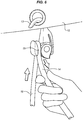
- FIG. 6 shows the self-locking hook in use to tie down a tarp 12 having an eyelet through which hook 13 passes.
- Cord 15 may be pulled by the user in the direction of the arrows shown.
- the cam will automatically release and section 16 of the rope may be reduced while section 14 is increased, thereby increasing tension.
- the cam will automatically lock when the cord 15 is released, due to the force of friction of the rope pulling the cam and the spring.
- FIGS. 7 and 8 show alternative embodiments of the self-locking hook.
- FIG. 7 shows a carabineer gate 17 included with cam 8.
- FIG. 8 shows an alternative to the hook that includes a body portion 18 that is configured to incorporate a strap 19. A variety of attachments may be incorporated in place of the hook or strap mechanism.
- FIGS. 9-13 show another embodiment of a self-locking hook 100.
- Self-locking hook 100 has many similarities to previous embodiments.
- Self-locking hook 100 includes a hook portion 110 that provides for hooking on various belts, loops, ropes, or objects.
- Hook portion 110 is closed by wire latch 115 which fits into notch 120.
- Receiving holes 122 provide for receiving the wire latch 115.
- Wire latch 115 is bent such that it tends to remain closed against notch 120.
- Aperture 125 is provided for passing a rope or cord through.
- Surface 128 opposes gripping surface 129 and provides for the locking of a rope or cord in the cam system of the self-locking hook 100. Gripping surface 129 is part of cam gripper 130.
- the body of the cam gripper includes a groove 145 having stop 150 which is interfaced with spring 140 having catch lip 155.
- Spring 140 is a straight arm spring in this embodiment.
- Spring 140 is integrated into the body of self-locking hook 100 and molded as the same piece of material in the embodiment shown.
- the shape of cam gripper 130 is elliptical and as it turns, it presses against spring 140, flexing it away from the body of self-locking hook 100.
- the catch lip 155 slides along groove (or channel) 145 until it reaches stop 150.
- Catch lip 155 also functions to prevent cam gripper 130 from being removed or pulled away from the body of self-locking hook 100.
- Catch lip 155 extends away from the surface of spring 140 so that it prevents cam gripper 130 from being pulled away.
- FIG. 10 shows the reverse side of self-locking hook 100.
- molding cutout 160 is visible. This cutout 160 allows for ease of molding and less plastic usage.
- Channel 165 provides for alignment of a cord as it is fed through aperture 125 and tensioned in place.
- FIG. 11 shows the self-locking hook 100 with cam gripper 130 removed.
- axel 210 is visible with cutout 220.
- Cam gripper 130 fits on this axel and rotates to provide gripping action.
- FIG. 12 show a close-up view of cam gripper 130; and
- FIG. 13 provides the rear view of cam gripper 130.
- Aperture 310 fits around axel 210 and provides for pivoting action of cam gripper 130.
- Cutout 320 provides for plastic savings and ease of molding.
- a cord is fed from the side of self-locking hook 100 that does not include cam gripper 130 through aperture 125 and then is pushed through cam gripper 130 if the rope is rigid enough; or cam gripper 130 may be actuated by the user to provide room for the cord to advance between surface 128 and gripper surface 129.
- the long end of the cord should be on the side opposite cam gripper 130. This is because, when the cord is pulled, friction will pull and tend to rotate cam gripper 130 towards surface 128 providing for increased gripping. If it is oriented the other way, or without going through the aperture 125 first, the pull will tend to release, since friction will pull cam gripper 130 open.
- Aperture 125 may also provide for a pivot point for tightening a cord passing through aperture 125 and cam gripper 130. Aperture 125 provides for a leverage point and, as the user pulls the cord through cam gripper 130, it will release tension. When the user releases the cord, the tension of the cord and spring 140 will tend to cause the cam gripper 130 to grip. The user may use the self-locking hook 100 in a ratcheting fashion this way, by pulling and releasing and having cam gripper 130 hold the cord and then pulling hard again to increase tension.
- FIG. 14 shows another embodiment of a self-locking clip.
- This version includes two cams 430A, 430B, one on either side of the device 400.
- Device 400 includes external straight springs 440 with catch lips 455 to prevent cams 430A, 430B from releasing.
- one of the cams 430A has a release tab 431.
- the cams may include channels 445 and stops 450. More slim gripping surfaces 432, 433 are included as opposed to the previously shown cord blocks.
- a cam 430B interacts with aperture 491 and provides for cord tensioning as above. This side also includes slot 490 for additional tying or hanging.
- the opposite side cam 430A with release tab 431 is designed for attaching to a piece of cloth, fabric, or tarp. For example, it may be used in conjunction with a tent or similar tarp.
- the body area 493 does not include an aperture since it is for grabbing fabric.
- the cam sides may match, both having an aperture.
- Cam 430A has an opposite configuration from cam 430B. In cam 430B, when a rope is pulled away from the device on the same side as cam 430B, the cam releases. If the rope is pulled away on the opposite side, cam 430B holds. In other words, clockwise rotation of cam 430B tends to hold the cord, and counterclockwise rotation tends to release the cord.
- FIG. 15 shows the device being used to hold a tarp and rope as would be used in conjunction with a tent.
- FIG. 16 shows device 400 on a hook supported by aperture 490 and a piece of fabric held in the opposite end. In this way, the device could be used for hanging clothes or other items.
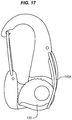
- FIG. 17 shows an alternative embodiment of the self-locking hook utilizing a metal spring arm 140A.
- This metal spring arm may be attached in the same fashion as the carabineer gate and functions similarly to the spring arm 140 above by applying force to cam 130.
- a variety of external arm type springs and internal springs may be used. The scope of this disclosure is intended to cover modifications as defined by the appended claims.
Landscapes
- Engineering & Computer Science (AREA)
- General Engineering & Computer Science (AREA)
- Mechanical Engineering (AREA)
- Clamps And Clips (AREA)
- Hooks, Suction Cups, And Attachment By Adhesive Means (AREA)
Claims (13)
- Selbsthemmende Klammer, die umfasst:einen Klammerkörper (1);einen drehbaren Nockengreifer (130), wobei der drehbare Nockengreifer (130) schwenkbar an dem Klammerkörper (1) befestigt ist;einen Federarm (140A), wobei der Federarm (140A) in den Klammerkörper (1) integriert ist, wobei der Federarm (140A) dazu eingerichtet ist, Spannung auf den drehbaren Nockengreifer (130) auszuüben, so dass der drehbare Nockengreifer (130) gegen eine erste Griffoberfläche (128) auf dem Klammerkörper (1) gehalten ist, wobei der drehbare Nockengreifer (130) asymmetrisch befestigt ist, wobei der drehbare Nockengreifer dazu eingerichtet ist, dass sich der drehbare Nockengreifer (130) zum Federarm (140A) erstreckt und den Federarm (140A) biegt, wenn sich der drehbare Nockengreifer (130) in eine erste Richtung dreht;wobei der drehbare Nockengreifer (130) eine erste Auskehlung (145) hat, wobei die erste Auskehlung (145) den Federarm (140A) berührt;dadurch gekennzeichnet, dassdie erste Auskehlung (145) in einen Anschlag (150) mündet, wobei der Anschlag (150) dazu eingerichtet ist, eine Überdrehung des drehbaren Nockengreifers (130) zu verhindern, und wobei die selbsthemmende Klammer eine Fanglippe (155) umfasst, wobei die Fanglippe (155) so dimensioniert ist, dass sie in die erste Auskehlung (145) passt, wobei die Fanglippe (155) dazu eingerichtet ist, sich senkrecht zu dem drehbaren Nockengreifer (130) und einer Drehrichtung des drehbaren Nockengreifers (130) zu erstrecken, so dass der drehbare Nockengreifer (130) nicht vom Klammerkörper (1) entfernt werden kann, ohne den Federarm (140A) vom drehbaren Nockengreifer (130) wegzuziehen.
- Selbsthemmende Klammer nach Anspruch 1, wobei eine erste Seite des Klammerkörpers (1) einen Schnurführungskanal (9) umfasst, der dazu eingerichtet ist, eine Schnur (15) über eine Kerbe (120) und in einen Griffbereich (493) zwischen den drehbaren Nockengreifer (130) und die erste Griffoberfläche (128) zu führen.
- Selbsthemmende Klammer nach Anspruch 2, wobei die Kerbe (120) in einer Öffnung (125) des Klammerkörpers (1) angeordnet ist.
- Selbsthemmende Klammer nach Anspruch 3, wobei der drehbare Nockengreifer (130) eine näherungsweise elliptische Form aufweist.
- Selbsthemmende Klammer nach Anspruch 4, wobei die näherungsweise elliptische Form ein spitzes und zulaufendes Ende an einem ersten Ende einer Hauptachse aufweist.
- Selbsthemmende Klammer nach Anspruch 5, wobei der drehbare Nockengreifer (130) eine achsaufnehmende Öffnung (310) umfasst, welche asymmetrisch im drehbaren Nockengreifer (130) angeordnet ist und dazu eingerichtet ist, eine sich vom Klammerkörper (1) erstreckende Achse (210) aufzunehmen.
- Selbsthemmende Klammer nach Anspruch 6, wobei die achsaufnehmende Öffnung (310) distal vom spitzen und zulaufenden Ende ist.
- Selbsthemmende Klammer nach Anspruch 7, wobei die selbsthemmende Klammer einen Hakenabschnitt (110) zum Anhaken der selbsthemmenden Klammer an ein Objekt aufweist.
- Selbsthemmende Klammer nach Anspruch 8, wobei der Hakenabschnitt (110) ein Karabiner-Tor (17) umfasst.
- Selbsthemmende Klammer nach Anspruch 9, wobei die asymmetrische Befestigung aufgrund des Kontakts zwischen dem drehbaren Nockengreifer (130) und der ersten Griffoberfläche (128) eine Verdrehung des drehbaren Nockengreifers (130) über die erste Griffoberfläche (128) hinaus verhindert.
- Selbsthemmende Klammer nach Anspruch 10, wobei der drehbare Nockengreifer (130) eine zweite Griffoberfläche (129) an einem Abschnitt hat, der mit der ersten Griffoberfläche (128) interagiert.
- Selbsthemmende Klammer nach Anspruch 11, wobei der drehbare Nockengreifer (130) so ausgerichtet ist, dass beim Ziehen der Schnur (15) in eine erste Richtung sich der drehbare Nockengreifer (130) zur ersten Griffoberfläche (128) hindreht und für zusätzlichen Halt der Schnur (15) sorgt.
- Selbsthemmende Klammer nach Anspruch 1, die weiterhin umfasst:eine Kerbe (120), die in einer Öffnung (125) des Klammerkörpers (1) angeordnet ist, und wobei der drehbare Nockengreifer (130) eine achsaufnehmende Öffnung (310) aufweist, welche asymmetrisch im drehbaren Nockengreifer (130) angeordnet ist und dazu eingerichtet ist, eine sich vom Klammerkörper (1) erstreckende Achse (210) aufzunehmen.
Applications Claiming Priority (2)
| Application Number | Priority Date | Filing Date | Title |
|---|---|---|---|
| US201161461541P | 2011-01-19 | 2011-01-19 | |
| PCT/US2012/021858 WO2012100046A1 (en) | 2011-01-19 | 2012-01-19 | Self-locking clip systems and methods |
Publications (3)
| Publication Number | Publication Date |
|---|---|
| EP2665639A1 EP2665639A1 (de) | 2013-11-27 |
| EP2665639A4 EP2665639A4 (de) | 2014-12-31 |
| EP2665639B1 true EP2665639B1 (de) | 2017-08-30 |
Family
ID=46489594
Family Applications (1)
| Application Number | Title | Priority Date | Filing Date |
|---|---|---|---|
| EP12736245.7A Active EP2665639B1 (de) | 2011-01-19 | 2012-01-19 | Systeme und verfahren mit einer selbstverriegelnden klemme |
Country Status (6)
| Country | Link |
|---|---|
| US (1) | US8997315B2 (de) |
| EP (1) | EP2665639B1 (de) |
| JP (1) | JP6026430B2 (de) |
| CN (1) | CN103328318B (de) |
| CA (1) | CA2824999C (de) |
| WO (1) | WO2012100046A1 (de) |
Families Citing this family (19)
| Publication number | Priority date | Publication date | Assignee | Title |
|---|---|---|---|---|
| US9199571B2 (en) * | 2012-07-03 | 2015-12-01 | Cequent Consumer Products, Inc. | Adjustable flexible cargo strap |
| AT513382B1 (de) * | 2012-10-17 | 2014-04-15 | Fischer Sports Gmbh | Klemmvorrichtung für ein Schnürelement |
| US8870145B1 (en) * | 2013-01-25 | 2014-10-28 | Gordon G. Carlson | Clothes hanging assembly |
| FR3026448B1 (fr) * | 2014-09-25 | 2017-05-05 | Zedel | Mousqueton a oeil perfectionne |
| US9797422B2 (en) | 2015-12-29 | 2017-10-24 | Winston Products, Llc | Sheet material clamp |
| USD798139S1 (en) | 2015-12-29 | 2017-09-26 | Winston Products, Llc. | Clamp |
| US10948127B2 (en) | 2017-07-06 | 2021-03-16 | Outdoor Products, Inc. | Tree-mountable bracket for canister stove or other camping equipment |
| CN107356476A (zh) * | 2017-08-22 | 2017-11-17 | 苏交科集团股份有限公司 | 一种丙纶绳检测夹具 |
| CN108045502A (zh) * | 2017-12-12 | 2018-05-18 | 威海市威力高档工具有限公司 | 船用缆绳快速固定连接器 |
| CN108464575A (zh) * | 2018-04-12 | 2018-08-31 | 庄玉选 | 一种鞋带紧固扣 |
| US10441035B1 (en) * | 2018-06-08 | 2019-10-15 | Duraflex Hong Kong Limited | Cord lock |
| IL280484B2 (en) | 2018-08-01 | 2024-05-01 | Manometal Solutions Ltd | Cable system and closure for it |
| CN112809623A (zh) * | 2019-11-15 | 2021-05-18 | 美国产品集团公司 | 具有负载张力组件的多功能工具组件 |
| CN111120579A (zh) * | 2020-01-21 | 2020-05-08 | 国网福建省电力有限公司 | 免绑扎式绳索扣 |
| CN113074172B (zh) * | 2021-03-25 | 2023-10-13 | 青岛铝小宝建筑有限公司 | 转子紧固件 |
| US12044040B2 (en) * | 2021-04-02 | 2024-07-23 | Brady Worldwide, Inc. | Cable lockout device |
| DE102023103123A1 (de) * | 2023-02-09 | 2024-08-14 | Andreas Stihl Ag & Co. Kg | Tragevorrichtung |
| US12234883B1 (en) | 2023-07-31 | 2025-02-25 | Nite Ize, Inc. | Rope restraining and selective release device |
| CN119655164B (zh) * | 2025-01-10 | 2026-02-24 | 山东理工大学 | 一种具有锁定功能的按钮式海带苗绳快速装卸结构 |
Family Cites Families (47)
| Publication number | Priority date | Publication date | Assignee | Title |
|---|---|---|---|---|
| US565699A (en) * | 1896-08-11 | Self-locking pulley-block | ||
| US201035A (en) * | 1878-03-05 | Improvement in picture-frame-cord holders | ||
| US436832A (en) * | 1890-09-23 | Clinton la grange | ||
| US916091A (en) | 1908-06-18 | 1909-03-23 | George J Batzer | Pulley and rope or cable holder. |
| US1250876A (en) * | 1917-02-16 | 1917-12-18 | Charles T Hicks | Clothes-line tightener. |
| US2942315A (en) * | 1959-04-17 | 1960-06-28 | Frank W Johnson | Line fastening device |
| US3091207A (en) * | 1961-07-10 | 1963-05-28 | Songer Mfg Company Inc | Water ski tow rope clamp |
| JPS49109768U (de) * | 1972-10-12 | 1974-09-19 | ||
| JPS5722876B2 (de) * | 1973-11-26 | 1982-05-15 | ||
| NL7700045A (nl) | 1977-01-05 | 1978-07-07 | Philips Nv | Trekontlastingsinrichting voor een kabel. |
| JPS5868512A (ja) * | 1981-09-29 | 1983-04-23 | ブリタツクス・エクセルシア・リミテツド | フアスナ− |
| US4465011A (en) * | 1982-07-19 | 1984-08-14 | Schaefer Marine, Inc. | Halyard stopper |
| JPS6360891A (ja) * | 1986-09-02 | 1988-03-16 | 三井ホ−ム株式会社 | パネルクランプ装置におけるクランプ調整機構 |
| US4716630A (en) * | 1987-01-20 | 1988-01-05 | Skyba Helmut K | Cam lock with positive release |
| US4766835A (en) * | 1987-09-10 | 1988-08-30 | Richard C. Randall | Rope cleat |
| FR2651843B1 (fr) * | 1989-09-12 | 1991-12-20 | Aerospatiale | Systeme de verrouillage a came. |
| US4998327A (en) * | 1990-04-11 | 1991-03-12 | Hull Harold L | Traction hook and rope lock |
| US4993123A (en) | 1990-06-07 | 1991-02-19 | Siwek Thomas J | Adjustable nautical rope lock |
| AU2444492A (en) | 1991-08-09 | 1993-03-02 | Helmut K. Skyba | Ratchet pulley for tightening cords or ropes |
| US6068242A (en) | 1994-04-25 | 2000-05-30 | Kingery; Gerald M. | Unitary, ridged and ratcheted pulley block |
| JP3027722U (ja) * | 1996-02-07 | 1996-08-13 | 東ポリ株式会社 | 衣服用樹脂クリップフック |
| FR2748078B1 (fr) | 1996-04-25 | 1998-06-12 | Zedel | Poulie a flasque pivotant et a bloqueur integre |
| JP3051338B2 (ja) * | 1996-05-21 | 2000-06-12 | 株式会社ジェイアール西日本テクノス | 施錠装置 |
| FR2753169A1 (fr) * | 1996-09-10 | 1998-03-13 | Lacan Guy Henri | Bloqueur de cordage a faible effort d'ouverture |
| DE19720335C1 (de) * | 1997-05-15 | 1998-11-19 | Joerg Feder | Längenverstellvorrichtung für Segelboot-Trapeze |
| US7234686B2 (en) | 1997-12-03 | 2007-06-26 | Peter Stone | Fail-safe cleat with automatic in-line locking cam and quick-release slot |
| US6742770B1 (en) | 1999-10-09 | 2004-06-01 | Peter V. Vassioukevitch | Fail-safe device for raising/lowering articles |
| US6234454B1 (en) | 1997-12-03 | 2001-05-22 | Peter V. Vassioukevitch | Failsafe device for raising/lowering articles |
| US7073780B2 (en) * | 1997-12-03 | 2006-07-11 | Peter Stone | Fail-safe cleat with automatic in-line locking cam |
| JP3052061U (ja) * | 1998-03-06 | 1998-09-11 | 章訓 中辻 | 戸袋内の雨戸固定装置 |
| US6115889A (en) * | 1999-01-22 | 2000-09-12 | Mickelson; Charles E. | Horse tether device and method of use thereof |
| US6292984B1 (en) * | 1999-09-27 | 2001-09-25 | Bradley E. Nelson | Load-support system employing instantaneously adjustable hook |
| IT1306692B1 (it) * | 1999-11-23 | 2001-10-02 | Zanata Spa | Dispositivo di blocco per lacci di calzature. |
| CA2334410C (en) | 2000-02-08 | 2005-10-25 | Basecamp Innovations, Ltd. | Force limiting rope brake |
| JP2003166599A (ja) * | 2001-11-28 | 2003-06-13 | Osaka Coat Rope Kk | ワイヤ類クランプ |
| FR2842113B1 (fr) * | 2002-07-12 | 2004-09-24 | Zedel | Dispositif antichute suiveur pour corde fixe |
| JP2004150622A (ja) * | 2002-09-03 | 2004-05-27 | Osaka Coat Rope Kk | ワイヤ類クランプ |
| US6925951B1 (en) * | 2004-02-09 | 2005-08-09 | Delong Mark | Boat docking rope cuffs |
| US7076844B2 (en) * | 2004-05-03 | 2006-07-18 | Skyba Helmut K | Open sided cam lock for ropes |
| CN101065317A (zh) * | 2004-06-24 | 2007-10-31 | 彼得·斯通 | 具有自动内嵌锁紧凸轮的夹板 |
| US7428769B2 (en) | 2004-11-08 | 2008-09-30 | Tie Boss Llc | Tie down tensioning device |
| US7111572B1 (en) | 2005-07-19 | 2006-09-26 | Formosa Saint Jose Corp. | Hook seat tightening structure for ship covers |
| US7287303B2 (en) | 2005-11-02 | 2007-10-30 | Formosa Saint Jose Corp. | Easy-type unidirectional locking device |
| US7287304B2 (en) * | 2005-12-20 | 2007-10-30 | Zebe Jr Charles W | Cam cleat construction |
| US7222840B1 (en) | 2006-03-21 | 2007-05-29 | Stepper Orval O | Rope-guiding device |
| US7445195B1 (en) | 2007-11-09 | 2008-11-04 | Han-Ching Huang | Pulley |
| US8881349B2 (en) * | 2011-06-09 | 2014-11-11 | Menno Mulholland | Adjustable holding device and associated adjustable connection mechanism |
-
2012
- 2012-01-19 US US13/353,831 patent/US8997315B2/en active Active
- 2012-01-19 WO PCT/US2012/021858 patent/WO2012100046A1/en not_active Ceased
- 2012-01-19 JP JP2013550576A patent/JP6026430B2/ja active Active
- 2012-01-19 CN CN201280005944.7A patent/CN103328318B/zh active Active
- 2012-01-19 CA CA2824999A patent/CA2824999C/en active Active
- 2012-01-19 EP EP12736245.7A patent/EP2665639B1/de active Active
Non-Patent Citations (1)
| Title |
|---|
| None * |
Also Published As
| Publication number | Publication date |
|---|---|
| JP2014505843A (ja) | 2014-03-06 |
| JP6026430B2 (ja) | 2016-11-16 |
| US8997315B2 (en) | 2015-04-07 |
| CA2824999C (en) | 2016-10-25 |
| EP2665639A1 (de) | 2013-11-27 |
| WO2012100046A1 (en) | 2012-07-26 |
| US20120180267A1 (en) | 2012-07-19 |
| EP2665639A4 (de) | 2014-12-31 |
| CA2824999A1 (en) | 2012-07-26 |
| CN103328318A (zh) | 2013-09-25 |
| CN103328318B (zh) | 2017-07-14 |
Similar Documents
| Publication | Publication Date | Title |
|---|---|---|
| EP2665639B1 (de) | Systeme und verfahren mit einer selbstverriegelnden klemme | |
| CN104270984B (zh) | 用于保持平坦带的系统和方法 | |
| EP2147231B1 (de) | Festbindungs- und spannungssystem | |
| EP2948014B1 (de) | Riemenfixieranordnung und system | |
| CN103523372A (zh) | 可调节柔性货物带条 | |
| US10548373B2 (en) | Systems and methods for a side-loading strap buckle | |
| US9254778B2 (en) | Adjustable cam buckle | |
| US7171731B1 (en) | Fastener with self-organizing device for storage | |
| US8348970B2 (en) | Military emergency tourniquet | |
| US20060266300A1 (en) | Retracting pet leash assembly | |
| US8245360B2 (en) | Rope grip slip-knot device | |
| US20130333169A1 (en) | Ratchet strap binder and method of adjusting a strap in length | |
| US20120017400A1 (en) | Cord clamping device | |
| US6401310B1 (en) | Snowshoe buckle | |
| US20140033485A1 (en) | Webbing tie down with friction roller | |
| TWI247695B (en) | A strap-tying device | |
| US20170290302A1 (en) | A clasp | |
| US20030131451A1 (en) | Dual action locking buckle device | |
| US20070067968A1 (en) | Connectable Bungee Cord | |
| US20110056050A1 (en) | Rope lok | |
| HK1188586A (en) | Self-locking clip systems and methods | |
| JP3965463B2 (ja) | 首輪用紐体 | |
| US20070059125A1 (en) | Set of baggage holders | |
| JPH11127937A (ja) | ストラップ |
Legal Events
| Date | Code | Title | Description |
|---|---|---|---|
| PUAI | Public reference made under article 153(3) epc to a published international application that has entered the european phase |
Free format text: ORIGINAL CODE: 0009012 |
|
| 17P | Request for examination filed |
Effective date: 20130718 |
|
| AK | Designated contracting states |
Kind code of ref document: A1 Designated state(s): AL AT BE BG CH CY CZ DE DK EE ES FI FR GB GR HR HU IE IS IT LI LT LU LV MC MK MT NL NO PL PT RO RS SE SI SK SM TR |
|
| DAX | Request for extension of the european patent (deleted) | ||
| A4 | Supplementary search report drawn up and despatched |
Effective date: 20141201 |
|
| RIC1 | Information provided on ipc code assigned before grant |
Ipc: B63B 21/08 20060101AFI20141125BHEP Ipc: F16G 11/10 20060101ALI20141125BHEP Ipc: F16G 11/14 20060101ALI20141125BHEP |
|
| GRAP | Despatch of communication of intention to grant a patent |
Free format text: ORIGINAL CODE: EPIDOSNIGR1 |
|
| RIC1 | Information provided on ipc code assigned before grant |
Ipc: F16G 11/14 20060101ALI20170308BHEP Ipc: B63B 21/08 20060101AFI20170308BHEP Ipc: F16G 11/10 20060101ALI20170308BHEP |
|
| INTG | Intention to grant announced |
Effective date: 20170327 |
|
| GRAS | Grant fee paid |
Free format text: ORIGINAL CODE: EPIDOSNIGR3 |
|
| GRAA | (expected) grant |
Free format text: ORIGINAL CODE: 0009210 |
|
| AK | Designated contracting states |
Kind code of ref document: B1 Designated state(s): AL AT BE BG CH CY CZ DE DK EE ES FI FR GB GR HR HU IE IS IT LI LT LU LV MC MK MT NL NO PL PT RO RS SE SI SK SM TR |
|
| REG | Reference to a national code |
Ref country code: GB Ref legal event code: FG4D |
|
| REG | Reference to a national code |
Ref country code: CH Ref legal event code: EP |
|
| REG | Reference to a national code |
Ref country code: AT Ref legal event code: REF Ref document number: 923250 Country of ref document: AT Kind code of ref document: T Effective date: 20170915 |
|
| REG | Reference to a national code |
Ref country code: IE Ref legal event code: FG4D |
|
| REG | Reference to a national code |
Ref country code: DE Ref legal event code: R096 Ref document number: 602012036618 Country of ref document: DE |
|
| REG | Reference to a national code |
Ref country code: NL Ref legal event code: FP |
|
| REG | Reference to a national code |
Ref country code: LT Ref legal event code: MG4D |
|
| REG | Reference to a national code |
Ref country code: AT Ref legal event code: MK05 Ref document number: 923250 Country of ref document: AT Kind code of ref document: T Effective date: 20170830 |
|
| PG25 | Lapsed in a contracting state [announced via postgrant information from national office to epo] |
Ref country code: AT Free format text: LAPSE BECAUSE OF FAILURE TO SUBMIT A TRANSLATION OF THE DESCRIPTION OR TO PAY THE FEE WITHIN THE PRESCRIBED TIME-LIMIT Effective date: 20170830 Ref country code: LT Free format text: LAPSE BECAUSE OF FAILURE TO SUBMIT A TRANSLATION OF THE DESCRIPTION OR TO PAY THE FEE WITHIN THE PRESCRIBED TIME-LIMIT Effective date: 20170830 Ref country code: FI Free format text: LAPSE BECAUSE OF FAILURE TO SUBMIT A TRANSLATION OF THE DESCRIPTION OR TO PAY THE FEE WITHIN THE PRESCRIBED TIME-LIMIT Effective date: 20170830 Ref country code: HR Free format text: LAPSE BECAUSE OF FAILURE TO SUBMIT A TRANSLATION OF THE DESCRIPTION OR TO PAY THE FEE WITHIN THE PRESCRIBED TIME-LIMIT Effective date: 20170830 Ref country code: NO Free format text: LAPSE BECAUSE OF FAILURE TO SUBMIT A TRANSLATION OF THE DESCRIPTION OR TO PAY THE FEE WITHIN THE PRESCRIBED TIME-LIMIT Effective date: 20171130 Ref country code: SE Free format text: LAPSE BECAUSE OF FAILURE TO SUBMIT A TRANSLATION OF THE DESCRIPTION OR TO PAY THE FEE WITHIN THE PRESCRIBED TIME-LIMIT Effective date: 20170830 |
|
| PG25 | Lapsed in a contracting state [announced via postgrant information from national office to epo] |
Ref country code: ES Free format text: LAPSE BECAUSE OF FAILURE TO SUBMIT A TRANSLATION OF THE DESCRIPTION OR TO PAY THE FEE WITHIN THE PRESCRIBED TIME-LIMIT Effective date: 20170830 Ref country code: IS Free format text: LAPSE BECAUSE OF FAILURE TO SUBMIT A TRANSLATION OF THE DESCRIPTION OR TO PAY THE FEE WITHIN THE PRESCRIBED TIME-LIMIT Effective date: 20171230 Ref country code: LV Free format text: LAPSE BECAUSE OF FAILURE TO SUBMIT A TRANSLATION OF THE DESCRIPTION OR TO PAY THE FEE WITHIN THE PRESCRIBED TIME-LIMIT Effective date: 20170830 Ref country code: GR Free format text: LAPSE BECAUSE OF FAILURE TO SUBMIT A TRANSLATION OF THE DESCRIPTION OR TO PAY THE FEE WITHIN THE PRESCRIBED TIME-LIMIT Effective date: 20171201 Ref country code: RS Free format text: LAPSE BECAUSE OF FAILURE TO SUBMIT A TRANSLATION OF THE DESCRIPTION OR TO PAY THE FEE WITHIN THE PRESCRIBED TIME-LIMIT Effective date: 20170830 Ref country code: BG Free format text: LAPSE BECAUSE OF FAILURE TO SUBMIT A TRANSLATION OF THE DESCRIPTION OR TO PAY THE FEE WITHIN THE PRESCRIBED TIME-LIMIT Effective date: 20171130 |
|
| PG25 | Lapsed in a contracting state [announced via postgrant information from national office to epo] |
Ref country code: PL Free format text: LAPSE BECAUSE OF FAILURE TO SUBMIT A TRANSLATION OF THE DESCRIPTION OR TO PAY THE FEE WITHIN THE PRESCRIBED TIME-LIMIT Effective date: 20170830 Ref country code: CZ Free format text: LAPSE BECAUSE OF FAILURE TO SUBMIT A TRANSLATION OF THE DESCRIPTION OR TO PAY THE FEE WITHIN THE PRESCRIBED TIME-LIMIT Effective date: 20170830 Ref country code: DK Free format text: LAPSE BECAUSE OF FAILURE TO SUBMIT A TRANSLATION OF THE DESCRIPTION OR TO PAY THE FEE WITHIN THE PRESCRIBED TIME-LIMIT Effective date: 20170830 Ref country code: RO Free format text: LAPSE BECAUSE OF FAILURE TO SUBMIT A TRANSLATION OF THE DESCRIPTION OR TO PAY THE FEE WITHIN THE PRESCRIBED TIME-LIMIT Effective date: 20170830 |
|
| PG25 | Lapsed in a contracting state [announced via postgrant information from national office to epo] |
Ref country code: EE Free format text: LAPSE BECAUSE OF FAILURE TO SUBMIT A TRANSLATION OF THE DESCRIPTION OR TO PAY THE FEE WITHIN THE PRESCRIBED TIME-LIMIT Effective date: 20170830 Ref country code: IT Free format text: LAPSE BECAUSE OF FAILURE TO SUBMIT A TRANSLATION OF THE DESCRIPTION OR TO PAY THE FEE WITHIN THE PRESCRIBED TIME-LIMIT Effective date: 20170830 Ref country code: SM Free format text: LAPSE BECAUSE OF FAILURE TO SUBMIT A TRANSLATION OF THE DESCRIPTION OR TO PAY THE FEE WITHIN THE PRESCRIBED TIME-LIMIT Effective date: 20170830 Ref country code: SK Free format text: LAPSE BECAUSE OF FAILURE TO SUBMIT A TRANSLATION OF THE DESCRIPTION OR TO PAY THE FEE WITHIN THE PRESCRIBED TIME-LIMIT Effective date: 20170830 |
|
| REG | Reference to a national code |
Ref country code: DE Ref legal event code: R097 Ref document number: 602012036618 Country of ref document: DE |
|
| PLBE | No opposition filed within time limit |
Free format text: ORIGINAL CODE: 0009261 |
|
| STAA | Information on the status of an ep patent application or granted ep patent |
Free format text: STATUS: NO OPPOSITION FILED WITHIN TIME LIMIT |
|
| 26N | No opposition filed |
Effective date: 20180531 |
|
| PG25 | Lapsed in a contracting state [announced via postgrant information from national office to epo] |
Ref country code: SI Free format text: LAPSE BECAUSE OF FAILURE TO SUBMIT A TRANSLATION OF THE DESCRIPTION OR TO PAY THE FEE WITHIN THE PRESCRIBED TIME-LIMIT Effective date: 20170830 |
|
| REG | Reference to a national code |
Ref country code: CH Ref legal event code: PL |
|
| PG25 | Lapsed in a contracting state [announced via postgrant information from national office to epo] |
Ref country code: LU Free format text: LAPSE BECAUSE OF NON-PAYMENT OF DUE FEES Effective date: 20180119 Ref country code: FR Free format text: LAPSE BECAUSE OF NON-PAYMENT OF DUE FEES Effective date: 20180131 |
|
| REG | Reference to a national code |
Ref country code: IE Ref legal event code: MM4A |
|
| REG | Reference to a national code |
Ref country code: FR Ref legal event code: ST Effective date: 20180928 |
|
| REG | Reference to a national code |
Ref country code: BE Ref legal event code: MM Effective date: 20180131 |
|
| PG25 | Lapsed in a contracting state [announced via postgrant information from national office to epo] |
Ref country code: BE Free format text: LAPSE BECAUSE OF NON-PAYMENT OF DUE FEES Effective date: 20180131 Ref country code: CH Free format text: LAPSE BECAUSE OF NON-PAYMENT OF DUE FEES Effective date: 20180131 Ref country code: LI Free format text: LAPSE BECAUSE OF NON-PAYMENT OF DUE FEES Effective date: 20180131 |
|
| PG25 | Lapsed in a contracting state [announced via postgrant information from national office to epo] |
Ref country code: IE Free format text: LAPSE BECAUSE OF NON-PAYMENT OF DUE FEES Effective date: 20180119 |
|
| PG25 | Lapsed in a contracting state [announced via postgrant information from national office to epo] |
Ref country code: MC Free format text: LAPSE BECAUSE OF FAILURE TO SUBMIT A TRANSLATION OF THE DESCRIPTION OR TO PAY THE FEE WITHIN THE PRESCRIBED TIME-LIMIT Effective date: 20170830 |
|
| PG25 | Lapsed in a contracting state [announced via postgrant information from national office to epo] |
Ref country code: MT Free format text: LAPSE BECAUSE OF NON-PAYMENT OF DUE FEES Effective date: 20180119 |
|
| PG25 | Lapsed in a contracting state [announced via postgrant information from national office to epo] |
Ref country code: TR Free format text: LAPSE BECAUSE OF FAILURE TO SUBMIT A TRANSLATION OF THE DESCRIPTION OR TO PAY THE FEE WITHIN THE PRESCRIBED TIME-LIMIT Effective date: 20170830 |
|
| PG25 | Lapsed in a contracting state [announced via postgrant information from national office to epo] |
Ref country code: PT Free format text: LAPSE BECAUSE OF FAILURE TO SUBMIT A TRANSLATION OF THE DESCRIPTION OR TO PAY THE FEE WITHIN THE PRESCRIBED TIME-LIMIT Effective date: 20170830 Ref country code: HU Free format text: LAPSE BECAUSE OF FAILURE TO SUBMIT A TRANSLATION OF THE DESCRIPTION OR TO PAY THE FEE WITHIN THE PRESCRIBED TIME-LIMIT; INVALID AB INITIO Effective date: 20120119 |
|
| PG25 | Lapsed in a contracting state [announced via postgrant information from national office to epo] |
Ref country code: MK Free format text: LAPSE BECAUSE OF NON-PAYMENT OF DUE FEES Effective date: 20170830 Ref country code: CY Free format text: LAPSE BECAUSE OF FAILURE TO SUBMIT A TRANSLATION OF THE DESCRIPTION OR TO PAY THE FEE WITHIN THE PRESCRIBED TIME-LIMIT Effective date: 20170830 |
|
| PG25 | Lapsed in a contracting state [announced via postgrant information from national office to epo] |
Ref country code: AL Free format text: LAPSE BECAUSE OF FAILURE TO SUBMIT A TRANSLATION OF THE DESCRIPTION OR TO PAY THE FEE WITHIN THE PRESCRIBED TIME-LIMIT Effective date: 20170830 |
|
| PGFP | Annual fee paid to national office [announced via postgrant information from national office to epo] |
Ref country code: NL Payment date: 20260126 Year of fee payment: 15 |
|
| PGFP | Annual fee paid to national office [announced via postgrant information from national office to epo] |
Ref country code: GB Payment date: 20260127 Year of fee payment: 15 |
|
| PGFP | Annual fee paid to national office [announced via postgrant information from national office to epo] |
Ref country code: DE Payment date: 20260128 Year of fee payment: 15 |