EP2665346A2 - Devices and methods for phase selection for a light - Google Patents
Devices and methods for phase selection for a light Download PDFInfo
- Publication number
- EP2665346A2 EP2665346A2 EP13168123.1A EP13168123A EP2665346A2 EP 2665346 A2 EP2665346 A2 EP 2665346A2 EP 13168123 A EP13168123 A EP 13168123A EP 2665346 A2 EP2665346 A2 EP 2665346A2
- Authority
- EP
- European Patent Office
- Prior art keywords
- phase
- operating device
- luminaire
- selection
- supply line
- Prior art date
- Legal status (The legal status is an assumption and is not a legal conclusion. Google has not performed a legal analysis and makes no representation as to the accuracy of the status listed.)
- Granted
Links
- 238000000034 method Methods 0.000 title claims abstract description 14
- 239000004020 conductor Substances 0.000 claims abstract description 60
- 238000005259 measurement Methods 0.000 claims description 6
- 230000004913 activation Effects 0.000 claims description 4
- 238000005286 illumination Methods 0.000 claims description 3
- 230000007935 neutral effect Effects 0.000 description 10
- 238000013461 design Methods 0.000 description 5
- 238000009826 distribution Methods 0.000 description 5
- 238000005516 engineering process Methods 0.000 description 4
- 239000004065 semiconductor Substances 0.000 description 4
- 238000004891 communication Methods 0.000 description 3
- 238000012544 monitoring process Methods 0.000 description 3
- 238000011161 development Methods 0.000 description 2
- 238000009434 installation Methods 0.000 description 2
- 230000003213 activating effect Effects 0.000 description 1
- 238000013459 approach Methods 0.000 description 1
- 238000005520 cutting process Methods 0.000 description 1
- 238000006073 displacement reaction Methods 0.000 description 1
- 230000000694 effects Effects 0.000 description 1
- 238000004870 electrical engineering Methods 0.000 description 1
- 238000011156 evaluation Methods 0.000 description 1
- 230000000977 initiatory effect Effects 0.000 description 1
- 238000002955 isolation Methods 0.000 description 1
- 238000012423 maintenance Methods 0.000 description 1
- 238000004519 manufacturing process Methods 0.000 description 1
- 230000005405 multipole Effects 0.000 description 1
- 230000001681 protective effect Effects 0.000 description 1
- 238000010187 selection method Methods 0.000 description 1
- 238000009827 uniform distribution Methods 0.000 description 1
Images


Classifications
-
- H—ELECTRICITY
- H05—ELECTRIC TECHNIQUES NOT OTHERWISE PROVIDED FOR
- H05B—ELECTRIC HEATING; ELECTRIC LIGHT SOURCES NOT OTHERWISE PROVIDED FOR; CIRCUIT ARRANGEMENTS FOR ELECTRIC LIGHT SOURCES, IN GENERAL
- H05B47/00—Circuit arrangements for operating light sources in general, i.e. where the type of light source is not relevant
- H05B47/10—Controlling the light source
- H05B47/175—Controlling the light source by remote control
-
- H—ELECTRICITY
- H05—ELECTRIC TECHNIQUES NOT OTHERWISE PROVIDED FOR
- H05B—ELECTRIC HEATING; ELECTRIC LIGHT SOURCES NOT OTHERWISE PROVIDED FOR; CIRCUIT ARRANGEMENTS FOR ELECTRIC LIGHT SOURCES, IN GENERAL
- H05B47/00—Circuit arrangements for operating light sources in general, i.e. where the type of light source is not relevant
- H05B47/10—Controlling the light source
-
- H—ELECTRICITY
- H02—GENERATION; CONVERSION OR DISTRIBUTION OF ELECTRIC POWER
- H02J—CIRCUIT ARRANGEMENTS OR SYSTEMS FOR SUPPLYING OR DISTRIBUTING ELECTRIC POWER; SYSTEMS FOR STORING ELECTRIC ENERGY
- H02J3/00—Circuit arrangements for ac mains or ac distribution networks
- H02J3/26—Arrangements for eliminating or reducing asymmetry in polyphase networks
-
- Y—GENERAL TAGGING OF NEW TECHNOLOGICAL DEVELOPMENTS; GENERAL TAGGING OF CROSS-SECTIONAL TECHNOLOGIES SPANNING OVER SEVERAL SECTIONS OF THE IPC; TECHNICAL SUBJECTS COVERED BY FORMER USPC CROSS-REFERENCE ART COLLECTIONS [XRACs] AND DIGESTS
- Y02—TECHNOLOGIES OR APPLICATIONS FOR MITIGATION OR ADAPTATION AGAINST CLIMATE CHANGE
- Y02E—REDUCTION OF GREENHOUSE GAS [GHG] EMISSIONS, RELATED TO ENERGY GENERATION, TRANSMISSION OR DISTRIBUTION
- Y02E40/00—Technologies for an efficient electrical power generation, transmission or distribution
- Y02E40/50—Arrangements for eliminating or reducing asymmetry in polyphase networks
-
- Y—GENERAL TAGGING OF NEW TECHNOLOGICAL DEVELOPMENTS; GENERAL TAGGING OF CROSS-SECTIONAL TECHNOLOGIES SPANNING OVER SEVERAL SECTIONS OF THE IPC; TECHNICAL SUBJECTS COVERED BY FORMER USPC CROSS-REFERENCE ART COLLECTIONS [XRACs] AND DIGESTS
- Y02—TECHNOLOGIES OR APPLICATIONS FOR MITIGATION OR ADAPTATION AGAINST CLIMATE CHANGE
- Y02P—CLIMATE CHANGE MITIGATION TECHNOLOGIES IN THE PRODUCTION OR PROCESSING OF GOODS
- Y02P80/00—Climate change mitigation technologies for sector-wide applications
- Y02P80/10—Efficient use of energy, e.g. using compressed air or pressurized fluid as energy carrier
Definitions
- the invention relates generally to an electrical arrangement with phase selection for powering a lamp, in particular a track or continuous line luminaire.
- Rail or continuous line lighting of extensive lighting systems are usually connected to a three-phase power grid.
- a multipolar ribbon cable is usually laid as a through-wiring, to which a plurality of juxtaposed rail or continuous line lights are connected.
- known power supply arrangements include a device for phase selection, which allows the optional connection of the operating device with a specific phase conductor of the polyphase supply line.
- the most uniform possible distribution to the different phases can be preset.
- Circuits for the centralized load balancing of the individual phases of a multi-phase supply network are known in electrical engineering.
- Such a switching device describes, for example, the patent US 5,604,385 or the registration US 2012/0078428 , With such central circuits a real load balance within a lighting system with a variety of lights is not readily possible.
- DE 38 18 078 proposes to integrate a rotary switch for phase selection in the connector, which is designed for electrical connection to a five-pin ribbon supply line.
- a power supply arrangement with plug connector according to DE 38 18 078 allows a cost-effective production and a simple manual phase selection when wiring the individual lights.
- a power supply arrangement for phase selection is provided for example in the luminaire insert for track lights, which is available under the product number 7692/58 E from TRILUX.
- This luminaire insert has an electronic ballast as a single-phase operating device for two fluorescent tubes.
- the supply arrangement has a connector for electrical connection to a three-phase supply network.
- a device for phase selection is integrated, similar to the devices described above DE 41 27 899 or DE 38 18 078 to that in order to single-phase Supply of the operating device to select specific phase conductor.
- a disadvantage of power supply arrangements with phase selection according to the aforementioned prior art is that when changing the load of the individual phase conductors or in case of failure of a particular phase always a manual intervention with a relatively large effort on each light is required.
- the publication DE 196 11 161 describes a safety lighting system with a phase monitoring and a switch for a phase selection, which selects that phase in the event of a fault, in which an undisturbed mains voltage is applied. Even with this device no load balance between the individual phases within the lighting system is possible.
- An object of the present invention is therefore to propose a power supply arrangement for a luminaire, which allows the phase selection without manual intervention on the respective luminaire and allows load balancing. This is achieved by a luminaire with the features according to claim 1, an operating device according to claim 7 or a power supply arrangement according to claim 15. A method for automatic phase selection according to claim 8 or 9 allows automatic load balancing.
- phase selection switch is provided for phase selection, which is designed to be electronically controllable and thus has a control input to the electronic control.
- a phase selection switch according to the invention is preferably connected as a separate component between a conventional electrical connector for the supply line and a conventional operating device, but could also be integrated into a specially adapted operating device or as in the connector.
- the selector switches are not primarily those switches which mechanically change the switching state, but more generally devices which fulfill the function of a selector switch, i. also electromechanical relays, semiconductor switches, etc.
- the phase selector switch is provided in the circuit arrangement between the terminal contacts of the connector and the actual operating device.
- phase selection switch can therefore be actuated automatically, in particular by remote control or by an automatic control device within the supply arrangement. The operator or technician can therefore select the desired phase without physical intervention on the lamp. This considerably simplifies the operation of large lighting systems in particular.
- the supply arrangement for actuating the phase selection switch comprises an electronic control unit, preferably an integrated control circuit for the electronic control of the phase selection switch via the control input.
- a digital control circuit in particular a microcontroller is provided.
- another application-specific configurable or programmable integrated circuit may be suitable, for example an ASIC, a DSP or an FPGA.
- the electronic control unit can be realized as a separate component of the luminaire or by utilizing already existing functionality, in particular the operating device control of the operating device. Furthermore, the phase selector switch can be realized as a separate component of the lamp or as part of the operating device.
- the power supply arrangement of the luminaire has means for determining the power consumption of the operating device or of the lighting device (s).
- a load-measuring device control can be used in the operating device, which is often already present in electronic ballasts.
- an additional measuring device can be provided on or in the phase selector switch.
- an electronic control circuit allows, in particular, an appropriate connection of the supply arrangement to a data bus, which enables a data exchange with the control circuit, for example via cable or radio.
- the control circuit preferably has a digital interface for data connection or for data exchange with other control circuits or a central control via a digital data bus.
- Preference is given in industrial Applications uses a wired data bus to avoid electromagnetic interference.
- an expedient embodiment of the electronic control circuit or control unit is designed to automatically determine the phase conductor for single-phase supply of the operating device and corresponding activation of the phase selection switch. For example, in the case of a failure or absence of the data bus, a purely random selection of the phase conductor can take place in order to achieve a uniform distribution of the load of the individual phases statistically or on average, at least in installations with a large number of individual luminaires.
- the proposed power supply arrangement with phase selection in the luminaire can be implemented in various ways.
- the operating device may comprise the electronic control unit, e.g. as a functional unit, which is realized by the microcontroller of the operating device. Accordingly, the operating device may have a control output for controlling the phase-selection switch.
- the control unit can also be implemented separately from the operating device as a physical unit and connected to the operating device via a data connection. Also possible is an embodiment in which all functions for phase selection are perceived by the operating device.
- the controllable phase selector switch is integrated into the operating device and the operating device control, in particular a microcontroller of the operating device, functionally forms the control unit.
- the invention also relates to a corresponding operating device with a connector for connection to a multi-phase supply line with a plurality of phase conductors.
- the operating device is characterized by a device for selecting the phase with an electronically controllable phase selector switch for selectively connecting the operating device to a specific phase conductor of the multiphase supply line, wherein the operating device for electronic control of the phase selector switch is executed.
- the phase conductor which is intended for single-phase supply of the operating device, selectable by the operating device itself.
- phase selector switch is designed electromechanically or semiconductor technology.
- An electromechanical design for example in the manner of a relay, has the advantage of galvanic isolation from the supply network.
- the semiconductor implementation for example using power transistors, may be less expensive and / or more robust.
- phase selector switch has an open position in which the operating device is de-energized, i. is not connected to any of the phase conductors.
- the solution according to the invention is readily suitable for installation in a light band module or in a track lamp unit.
- the proposed supply arrangement or the proposed operating device enables advantageous methods for automatic phase selection, in particular for emergency operation in the event of a phase failure and / or for generating an approximately equally distributed utilization of the live or available phase conductors.
- a first Monitoring or determination of the availability of the individual phase conductors of the multiphase supply line is carried out and based on this, optionally by the respective control circuit or control unit, an electronic control of the phase selector of each lamp, so that a still available, ie voltage leading phase conductor is selected.
- all luminaires can be supplied by non-failed phase conductors.
- the original configuration ie the original distribution of the luminaire to the individual phases, can also be restored automatically by an analogous method.
- phase selector switch of each lamp to select a phase conductor is carried out so that over the phase conductor approximately equally distributed load is achieved by the lights.
- the determination of the load state of the individual phase conductors of the supply line and optionally also the determination of the availability of the individual phase conductors of the supply line is decentralized, in particular based on the means for determining the power consumption in the respective power supply arrangement of the individual lights.
- phase selection by determining the power consumption in the individual lights and on this basis, the electronic control of the phase selector of each lamp to select a phase conductor, ie the load balance is based on the decentrally determined power consumption of the individual lights. This way can be automatic and At arbitrary times, a load approximately equal over the available phase conductors can be achieved.
- the aforementioned determination of the availability and / or load and the electronic control of each lamp are performed by a central controller, with which the power supply arrangement of each lamp is connected via a data bus.
- the control unit itself may be designed to communicate directly with other controllers and to provide remote control. Thus, negotiation of an optimal load distribution can take place even without central control, in particular in the event of a phase failure.
- the determined power consumption in a luminaire is transmitted by the control unit of this luminaire on the basis of a data connection, in particular the other of the several luminaires and / or a central control.
- the invention also relates to the power supply arrangement per se and to an illumination system for automatic phase selection with a plurality of lights according to the present description.
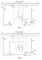
- FIG.1 schematically a first example of a power supply arrangement 100 is shown.
- the power supply arrangement 100 is used to power a lamp 110 and is arranged for this purpose in the housing 112 of the lamp.
- the luminaire 110 is preferably a component of a comprehensive illumination system with a multiplicity of individual luminaires 110, preferably a track luminaire or a luminaire module of a light band.
- the power supply arrangement 100 comprises an operating device 114, which ensures the appropriate supply of one or more connected bulbs 116, for example, two T5 fluorescent lamps.
- the operating device 114 is of conventional design, for example an electronic ballast, and is to be supplied with single-phase alternating current.
- the power supply arrangement 100 comprises an electrical connector 122, which is shown only schematically here.
- the connector 122 in the embodiment shown in FIG.1 shown embodiment, the connection to a supply line 120 with three phase conductors L1, L2, L3.
- a standardized connector 122 for building technology for example, according to DIN VDE 0606-201 (: 2004-09) is preferred, such as plug-in, clamp or cutting connector for common flat-band or round-sheath lines.
- the connector 122 includes, for each of the plurality of phase conductors L1, L2, L3, a corresponding line terminal 124-1, 124-2, 124-3.
- the multi-pole connector 122 further has a terminal 126 for the neutral or neutral conductor N and may optionally have a further connection for a protective conductor, not shown here.
- phase selection switch 130 is provided as a separate component according to the invention.
- the phase selection switch 130 may be implemented in any suitable manner for the purpose of its electronic control, for example electromechanically as a relay or in semiconductor technology, such as MOSFET power transistors.
- the phase selector switch 130 is connected on the input side by respective connections to each of the plurality of line contacts 124-1, 124-2, 124-3 and on the output side to the phase connection of the operating device 114 connected. How out FIG.1 schematically can the phase selector switch 130 for selectable or adjustable connection with a phase conductor L1, L2, L3 for each of the line contacts 124-1, 124-2, 124-3 a corresponding switching position and additionally an open position. In the off position of the phase selector 130, the operating device 114 is de-energized to allow, for example, an automatic safety shutdown.
- phase selection switch 130 comprises a purely schematically illustrated control input 132, which may not necessarily be designed as an externally accessible connection, but also within an integrated circuit.
- an integrated control circuit 140 for example a microcontroller, is provided in the power supply arrangement 100 as an electronic control unit.
- the control circuit 140 has a digital interface, indicated schematically at 142, for a wired data bus 144, which is implemented in a manner known per se.
- the control circuit 140 can autonomously or automatically decide which phase is selected to supply the operating device 114.
- the microcontroller can be programmed with a corresponding selection algorithm.
- a plurality of control circuits 140 in combination can form an ad hoc network without central control and mutually agree on a specific phase selection, with respect to one current operating situation to effect optimal distribution.
- a corresponding communication protocol for data exchange is implemented in the control circuit 140 by programming.
- the control circuit 140 either generates a corresponding electronic control signal to drive the control input 132 of the phase selector switch 130 either autonomously due to the algorithm or based on the data received via the data bus 144.
- the phase selector switch 130 can be implemented as a separate component or together with the control circuit 140 as an integrated circuit be executed.
- FIG.2 shows a second embodiment of a power supply arrangement 200 according to the invention, which differs from the example according to FIG.1 only differs in that the control circuit 140 has an air interface 242 and the data bus 244 is designed accordingly wirelessly.
- the data bus 244 via a suitable radio or infrared connection, for example. WLAN, Bluetooth, or similar. be realized in order to avoid additional wiring.
- FIG. 3 shows a further possible variant of a power supply arrangement 300, which like the example according to FIG.1 a digital interface 342 to a wired data bus 344 has.
- the difference to FIG.1 consists in that the already existing supply line 320 is used as a carrier line for the data bus 344.
- the digital interface 342 is implemented in a suitable network technology, for example analogously to the PowerLAN (dLAN, PCL) principle. This solution also avoids additional wiring.
- FIG.4 shows a further possible variant of a power supply arrangement 400, in which completely to a digital interface is dispensed with communication.
- the activation of the phase selection switch 430 takes place with the control unit 440 FIG.4 only self-sufficient or independent. This can be done, for example, by a random-based algorithm by programming the control circuit 440 appropriately.
- a data bus is thus not present in this simplified solution, which is particularly suitable for very large systems.
- FIG. 5 illustrates a development of the above embodiments, wherein the power supply assembly 500 or the light 510 comprises an additional power measurement circuit 550, which may be integrated into, for example, the phase selection switch 530 or connected thereto as a separate component.
- the power measurement circuit 550 determines the power consumption of the operating device 514 in a known manner by current and voltage measurement at the selected phase conductor 524-1 ... 524-3.
- the power measurement circuit 550 is connected to the control circuit 540.
- control circuit 540 taking into account, if necessary, additional data exchanged via the wireless or data bus 544, can collect additional lights or other control circuits 540 and information about the load situation in the lighting system and control the phase selection switch 530 accordingly for load balancing.
- FIG.6 illustrates a further embodiment, wherein a determination of the power consumption takes place by utilizing already existing in the operating device 614 functions.
- Today's electronic ballasts usually already have a power u. Voltage monitoring on the lamp, for example, to comply with the load limit of the operating device 614.
- the control circuit 640 Using a load-measuring equipment control unit 615, the power consumption of the one or more lamps can be communicated to the control circuit 640. This is the from the Operating unit 614 separately executed control unit 640, as in FIG.6 shown connected to the operating device 614 via a data link 617, which may be designed proprietary or standardized.
- the determination of the power consumption takes place decentrally in the individual luminaires.
- the load of the phase conductors 524-1 ... 524-3; 624-1 ... 624-3 are approximately equally distributed.
- the determined power consumption of a luminaire 510, 610 is communicated by the control unit 540, 640 of this luminaire via the data connection 544, 644 to the control units or control circuits 540, 640 of the other luminaires.
- the respective load information can be additionally or alternatively also transmitted to a central control for evaluation.
- FIG.7 shows a further variant of a power supply arrangement 700, in particular based on the embodiment according to FIG.6 ,
- the control unit 740 is not a separate component, but a component of the operating unit 714.
- the control unit 740 can be implemented, for example, as a functional unit, for example by the microcontroller already present for controlling the operating unit 714.
- the operating device 714 has a special control output, which is connected to the control input 732 for controlling the separately executed phase selector switch 730.
- a digital interface 742 of the operating device 714 can be used for data connection 714, which is also already present, eg a DALI interface of Operating device 742.
- FIG.8 finally shows a further inventive Further development, in particular starting from the variant according to FIG.7 in which also the controllable phase selection switch 830 is integrated in the operating device 814.
- the operating device control in particular the typical microcontroller of the operating device 814, expediently implements the function of the electronic control unit 840 for activating the phase-selection switch 830.
- the data communication relating to the load balancing or the phase selection takes place via an interface 842 of the operating device 814.
- control unit 140 ... 840 it is expedient to associate with the control unit 140 ... 840 an auxiliary supply of known design so that the operational readiness is ensured even after the safety shutdown or loss of the voltage on the currently selected phase conductor.
- a standby or auxiliary supply of the control unit 140 ... 840 can be realized by utilizing the data bus 144 ... 844.
- FIG.1 The power supply arrangement 110 lamp 112 luminaire housing 114 control gear 116 lamp 120 supply line L1, L2, L3 phase conductor N neutral 122 Interconnects 124-1, ...- 2, ...- 3, 226 line connection 130 Phase Selector 132 control input 140 control circuit 142 digital interface 144 bus FIG.2 200
Abstract
Description
Die Erfindung betrifft allgemein eine elektrische Anordnung mit Phasenwahl zur Stromversorgung einer Leuchte, insbesondere einer Schienen- oder Lichtbandleuchte.The invention relates generally to an electrical arrangement with phase selection for powering a lamp, in particular a track or continuous line luminaire.
Schienen- oder Lichtbandleuchten umfangreicher Beleuchtungsanlagen, etwa im industriellen Bereich wie beispielsweise in Werkshallen, werden meist an ein Dreiphasen-Stromnetz angeschlossen. Hierzu wird üblicherweise ein mehrpoliges Flachbandkabel als Durchgangsverdrahtung verlegt, an welches eine Mehrzahl aneinandergereihter Schienen- oder Lichtbandleuchten angeschlossen werden.Rail or continuous line lighting of extensive lighting systems, for example in the industrial sector, such as in factory halls, are usually connected to a three-phase power grid. For this purpose, a multipolar ribbon cable is usually laid as a through-wiring, to which a plurality of juxtaposed rail or continuous line lights are connected.
Aus Kostengründen werden herkömmliche, d.h. einphasig zu betreibende Betriebsgeräte für die Leuchtmittel eingesetzt. Um dennoch eine möglichst gleichmäßige Belastung des Dreiphasen-Stromnetzes durch jeweils nur an eine Phase angeschlossene Betriebsgeräte zu erzielen, umfassen bekannte Stromversorgungsanordnungen eine Vorrichtung zur Phasenwahl, welche das wahlweise Verbinden des Betriebsgeräts mit einem bestimmten Phasenleiter der mehrphasigen Versorgungsleitung ermöglicht. So kann beim Anschluss vor Ort eine möglichst gleichmäßige Verteilung auf die unterschiedlichen Phasen voreingestellt werden. Mit den zu erwartenden stetig verbesserten Wirkungsgraden der Leuchtmittel wird dem Lastausgleich zukünftig größere Bedeutung beikommen, um eine durch reduzierte Leistungsaufnahme bedingte Lastasymmetrie bei Erneuerung einzelner Leuchtmittel zu verhindern.For cost reasons, conventional, ie single-phase operated operating devices are used for the lamps. However, in order to achieve the most uniform possible loading of the three-phase power supply by only one phase connected to operating equipment, known power supply arrangements include a device for phase selection, which allows the optional connection of the operating device with a specific phase conductor of the polyphase supply line. Thus, when connecting on site, the most uniform possible distribution to the different phases can be preset. With the expected steadily improved efficiencies of the bulbs, load balancing will become more important in the future in order to achieve load asymmetry due to reduced power consumption to prevent renewal of individual bulbs.
Schaltungen zum zentralisierten Lastausgleich der einzelnen Phasen eines mehrphasigen Versorgungsnetzes sind in der Elektrotechnik bekannt. Eine solche Schalteinrichtung beschreibt z.B. das Patent
Zum Anschluss einer Schienenleuchte an eine mehrphasige Versorgungsleitung ist ein Steckverbinder mit einer Vorrichtung zur Phasenwahl aus der Offenlegungsschrift
Ein weiterer Ansatz ist beispielsweise aus der Offenlegungsschrift
Eine Stromversorgungsanordnung zur Phasenwahl ist beispielsweise im Leuchteneinsatz für Schienenleuchten vorgesehen, welcher unter der Produktnummer 7692/58 E von der Fa. TRILUX erhältlich ist. Dieser Leuchteneinsatz hat ein elektronisches Vorschaltgerät als einphasiges Betriebsgerät für zwei Leuchtstoffröhren. Die Versorgungsanordnung hat einen Steckverbinder zum elektrischen Anschluss an ein Dreiphasen-Versorgungsnetz. In diesen Steckverbinder ist eine Vorrichtung zur Phasenwahl integriert, ähnlich den oben beschriebenen Vorrichtungen aus
Nachteilig bei Stromversorgungsanordnungen mit Phasenwahl gemäß vorgenanntem Stand der Technik ist jedoch, dass bei Änderung der Belastung der einzelnen Phasenleiter oder bei Ausfall einer bestimmten Phase stets ein manueller Eingriff mit verhältnismäßig großem Aufwand an jeder betroffenen Leuchte erforderlich ist.A disadvantage of power supply arrangements with phase selection according to the aforementioned prior art, however, is that when changing the load of the individual phase conductors or in case of failure of a particular phase always a manual intervention with a relatively large effort on each light is required.
Aus der Offenlegungsschrift
Die Offenlegungsschrift
Eine Aufgabe der vorliegenden Erfindung ist es mithin, eine Stromversorgungsanordnung für eine Leuchte vorzuschlagen, welche die Phasenwahl ohne manuellen Eingriff an der jeweiligen Leuchte ermöglicht und einen Lastausgleich ermöglicht. Dies wird erzielt durch eine Leuchte mit den Merkmalen gemäß Anspruch 1, ein Betriebsgerät nach Anspruch 7 oder eine Stromversorgungsanordnung nach Anspruch 15. Ein Verfahren zur automatischen Phasenwahl gemäß Anspruch 8 bzw. 9 ermöglicht den automatischen Lastausgleich.An object of the present invention is therefore to propose a power supply arrangement for a luminaire, which allows the phase selection without manual intervention on the respective luminaire and allows load balancing. This is achieved by a luminaire with the features according to
In einer besonders einfachen Gestaltung zeichnet sich die erfindungsgemäße Lösung dadurch aus, dass zur Phasenwahl ein Phasenwahlschalter vorgesehen wird, welcher elektronisch steuerbar ausgeführt ist und somit einen Steuereingang zur elektronischen Ansteuerung aufweist. Ein Phasenwahlschalter im Sinne der Erfindung wird vorzugsweise als separate Komponente zwischen einem herkömmlichen elektrischen Verbinder für die Versorgungsleitung und einem herkömmlichen Betriebsgerät angeschlossen, könnte aber auch in ein speziell angepasstes Betriebsgerät oder etwa in den Verbinder integriert werden. Als Wahlschalter sind vorliegend demnach nicht hauptsächlich solche Schalter zu verstehen, welche mechanisch den Schaltzustand verändern, sondern ganz allgemein Vorrichtungen, welche die Funktion eines Wahlschalters erfüllen, d.h. auch elektromechanische Relais, Halbleiterschalter usw. In jedem Fall ist der Phasenwahlschalter in der Anordnung schaltungstechnisch zwischen den Anschlusskontakten des Verbinders und dem eigentlichen Betriebsgerät vorgesehen.In a particularly simple design, the solution according to the invention is characterized in that a phase selection switch is provided for phase selection, which is designed to be electronically controllable and thus has a control input to the electronic control. A phase selection switch according to the invention is preferably connected as a separate component between a conventional electrical connector for the supply line and a conventional operating device, but could also be integrated into a specially adapted operating device or as in the connector. Accordingly, the selector switches are not primarily those switches which mechanically change the switching state, but more generally devices which fulfill the function of a selector switch, i. also electromechanical relays, semiconductor switches, etc. In any case, the phase selector switch is provided in the circuit arrangement between the terminal contacts of the connector and the actual operating device.
Diese Gestaltung ermöglicht es, den Phasenleiter, welcher zur einphasigen Versorgung des Betriebsgeräts bestimmt ist, durch elektronische Ansteuerung des Phasenwahlschalters über den Steuereingang zu wählen. Demnach ist ein manueller Eingriff zur Betätigung des Wahlschalters oder eine Umstellung der Kontakte am Verbinder nicht erforderlich. Der erfindungsgemäße Phasenwahlschalter kann demnach automatisch, insbesondere durch Fernbedienung oder durch eine selbsttätige Steuervorrichtung innerhalb der Versorgungsanordnung, betätigt werden. Der Bediener bzw. Techniker kann also ohne physischen Eingriff an der Leuchte die gewünschte Phase auswählen. Dies vereinfacht insbesondere den Betrieb großer Beleuchtungsanlagen erheblich.This design makes it possible to select the phase conductor, which is intended for single-phase supply of the operating device, by electronic control of the phase selector switch via the control input. Accordingly, a manual intervention to operate the selector switch or a change of the contacts on the connector is not required. The phase selection switch according to the invention can therefore be actuated automatically, in particular by remote control or by an automatic control device within the supply arrangement. The operator or technician can therefore select the desired phase without physical intervention on the lamp. This considerably simplifies the operation of large lighting systems in particular.
Erfindungsgemäß umfasst die Versorgungsanordnung zur Betätigung des Phasenwahlschalters eine elektronische Steuereinheit, vorzugsweise eine integrierte Steuerschaltung zur elektronischen Ansteuerung des Phasenwahlschalters über den Steuereingang. Bevorzugt wird eine digitaltechnische Steuerschaltung, insbesondere ein Mikrokontroller vorgesehen. Geeignet kann jedoch auch eine andere anwendungsspezifisch konfigurierbare bzw. programmierbare integrierte Schaltung (IC) sein, beispielsweise ein ASIC, ein DSP oder ein FPGA.According to the invention, the supply arrangement for actuating the phase selection switch comprises an electronic control unit, preferably an integrated control circuit for the electronic control of the phase selection switch via the control input. Preferably, a digital control circuit, in particular a microcontroller is provided. However, another application-specific configurable or programmable integrated circuit (IC) may be suitable, for example an ASIC, a DSP or an FPGA.
Die elektronische Steuereinheit kann als getrenntes Bauteil der Leuchte oder unter Ausnutzung bereits vorhandener Funktionalität, insbesondere der Betriebsgerätesteuerung des Betriebsgeräts, realisiert werden. Ferner kann auch der Phasenwahlschalter als getrenntes Bauteil der Leuchte oder aber als Bestandteil des Betriebsgeräts realisiert sein.The electronic control unit can be realized as a separate component of the luminaire or by utilizing already existing functionality, in particular the operating device control of the operating device. Furthermore, the phase selector switch can be realized as a separate component of the lamp or as part of the operating device.
In vorteilhafter Ausführung weist die Stromversorgungsanordnung der Leuchte Mittel zur Ermittlung der Leistungsaufnahme des Betriebsgeräts oder des bzw. der Leuchtmittel auf. Hierzu kann eine die Last messende Betriebsgerätesteuerung im Betriebsgerät genutzt werden, welche in elektronischen Vorschaltgeräten oft bereits vorliegt. Alternativ oder ergänzend kann eine zusätzliche Messvorrichtung am oder im Phasenwahlschalter vorgesehen werden.In an advantageous embodiment, the power supply arrangement of the luminaire has means for determining the power consumption of the operating device or of the lighting device (s). For this purpose, a load-measuring device control can be used in the operating device, which is often already present in electronic ballasts. Alternatively or additionally, an additional measuring device can be provided on or in the phase selector switch.
Die Verwendung einer elektronischen Steuerschaltung ermöglicht insbesondere eine zweckmäßige Anbindung der Versorgungsanordnung an einen Datenbus, welcher einen Datenaustausch mit der Steuerschaltung, beispielsweise über Kabel oder Funk, ermöglicht. Hierzu weist die Steuerschaltung vorzugsweise eine digitale Schnittstelle auf zur Datenverbindung bzw. zum Datenaustausch mit anderen Steuerschaltungen oder einer Zentral steuerung über einen digitalen Datenbus. Bevorzugt wird in industriellen Anwendungen ein kabelgebundener Datenbus verwendet, um elektromagnetische Störungen zu vermeiden.The use of an electronic control circuit allows, in particular, an appropriate connection of the supply arrangement to a data bus, which enables a data exchange with the control circuit, for example via cable or radio. For this purpose, the control circuit preferably has a digital interface for data connection or for data exchange with other control circuits or a central control via a digital data bus. Preference is given in industrial Applications uses a wired data bus to avoid electromagnetic interference.
Alternativ oder ergänzend zur Fernsteuerung des Phasenwahlschalters über einen Datenbus ist eine zweckmäßige Ausführung der elektronischen Steuerschaltung bzw. Steuereinheit so, dass diese zur selbsttätigen Bestimmung des Phasenleiters zur einphasigen Versorgung des Betriebsgeräts und entsprechenden Ansteuerung des Phasenwahlschalters ausgeführt ist. Es kann beispielsweise bei Ausfall oder Fehlen des Datenbus eine rein zufallsbasierte Auswahl des Phasenleiters erfolgen, um statistisch bzw. im Mittel zumindest bei Anlagen mit einer großen Anzahl einzelner Leuchten eine Gleichverteilung der Belastung der einzelnen Phasen zu erzielen.Alternatively or in addition to the remote control of the phase selector switch via a data bus, an expedient embodiment of the electronic control circuit or control unit is designed to automatically determine the phase conductor for single-phase supply of the operating device and corresponding activation of the phase selection switch. For example, in the case of a failure or absence of the data bus, a purely random selection of the phase conductor can take place in order to achieve a uniform distribution of the load of the individual phases statistically or on average, at least in installations with a large number of individual luminaires.
Die vorgeschlagene Stromversorgungsanordnung mit Phasenwahl in der Leuchte kann auf verschiedene Arten umgesetzt werden. Das Betriebsgerät kann die elektronische Steuereinheit umfassen, z.B. als Funktionseinheit, welche durch den Mikrocontroller des Betriebsgeräts realisiert wird. Entsprechend kann das Betriebsgerät einen Steuerausgang zur Ansteuerung des Phasenwahlschalters aufweisen. Die Steuereinheit kann jedoch auch vom Betriebsgerät getrennt als physische Einheit ausgeführt sein und mit dem Betriebsgerät über eine Datenverbindung verbunden werden. Ebenfalls möglich ist eine Ausführung, in welcher alle Funktionen zur Phasenwahl vom Betriebsgerät wahrgenommen werden. In dieser Ausführung ist der steuerbare Phasenwahlschalter in das Betriebsgerät integriert und die Betriebsgerätesteuerung, insbesondere ein Mikrocontroller des Betriebsgeräts, bildet funktional die Steuereinheit.The proposed power supply arrangement with phase selection in the luminaire can be implemented in various ways. The operating device may comprise the electronic control unit, e.g. as a functional unit, which is realized by the microcontroller of the operating device. Accordingly, the operating device may have a control output for controlling the phase-selection switch. However, the control unit can also be implemented separately from the operating device as a physical unit and connected to the operating device via a data connection. Also possible is an embodiment in which all functions for phase selection are perceived by the operating device. In this embodiment, the controllable phase selector switch is integrated into the operating device and the operating device control, in particular a microcontroller of the operating device, functionally forms the control unit.
Die Erfindung betrifft ebenfalls ein entsprechendes Betriebsgerät mit einem Verbinder zum Anschluss an eine mehrphasige Versorgungsleitung mit mehreren Phasenleitern. Das Betriebsgerät zeichnet sich aus durch eine Vorrichtung zur Phasenwahl mit einem elektronisch steuerbaren Phasenwahlschalter zum wahlweisen Verbinden des Betriebsgeräts mit einem bestimmten Phasenleiter der mehrphasigen Versorgungsleitung, wobei das Betriebsgerät zur elektronischen Ansteuerung des Phasenwahlschalters ausgeführt ist. Hierdurch wird der Phasenleiter, welcher zur einphasigen Versorgung des Betriebsgeräts bestimmt ist, durch das Betriebsgerät selbst wählbar.The invention also relates to a corresponding operating device with a connector for connection to a multi-phase supply line with a plurality of phase conductors. The operating device is characterized by a device for selecting the phase with an electronically controllable phase selector switch for selectively connecting the operating device to a specific phase conductor of the multiphase supply line, wherein the operating device for electronic control of the phase selector switch is executed. As a result, the phase conductor, which is intended for single-phase supply of the operating device, selectable by the operating device itself.
Grundsätzlich sind unterschiedliche Arten der Ausführung des Phasenwahlschalters geeignet. Zweckmäßig ist der Phasenwahlschalter elektromechanisch oder halbleitertechnisch ausgeführt. Eine elektromechanische Ausführung, beispielsweise in der Art eines Relais, hat den Vorteil der galvanischen Trennung vom Versorgungsnetz. Die halbleitertechnische Ausführung, beispielsweise unter Verwendung von Leistungstransistoren, kann kostengünstiger und/oder robuster sein.In principle, different types of execution of the phase selector switch are suitable. Suitably, the phase selector switch is designed electromechanically or semiconductor technology. An electromechanical design, for example in the manner of a relay, has the advantage of galvanic isolation from the supply network. The semiconductor implementation, for example using power transistors, may be less expensive and / or more robust.
Um zusätzlich zur automatischen Phasenwahl auch eine fernbediente Abschaltung, etwa zu Sicherheitszwecken bei Wartungsarbeiten, zu ermöglichen, ist es vorteilhaft, wenn der Phasenwahlschalter eine Ausschaltstellung aufweist, bei welcher das Betriebsgerät spannungsfrei geschaltet ist, d.h. mit keinem der Phasenleiter verbunden ist.In addition to the automatic phase selection to allow a remote-controlled shutdown, such as for safety purposes during maintenance, it is advantageous if the phase selector switch has an open position in which the operating device is de-energized, i. is not connected to any of the phase conductors.
Die erfindungsgemäße Lösung eignet sich ohne Weiteres zum Einbau in ein Lichtbandmodul oder in eine Schienenleuchteneinheit.The solution according to the invention is readily suitable for installation in a light band module or in a track lamp unit.
Ferner ermöglicht die vorgeschlagene Versorgungsanordnung bzw. das vorgeschlagene Betriebsgerät vorteilhafte Verfahren zur automatischen Phasenwahl, insbesondere zum Notbetrieb bei Ausfall einer Phase und/oder zur Erzeugung einer näherungsweise gleich verteilten Auslastung der spannungsführenden bzw. verfügbaren Phasenleiter.Furthermore, the proposed supply arrangement or the proposed operating device enables advantageous methods for automatic phase selection, in particular for emergency operation in the event of a phase failure and / or for generating an approximately equally distributed utilization of the live or available phase conductors.
Bei Ausfall ist es zweckmäßig, wenn zunächst eine Überwachung oder Ermittlung der Verfügbarkeit der einzelnen Phasenleiter der mehrphasigen Versorgungsleitung erfolgt und hierauf gründend, ggf. durch die jeweilige Steuerschaltung bzw. Steuereinheit, eine elektronische Ansteuerung des Phasenwahlschalters jeder Leuchte erfolgt, so dass ein noch verfügbarer, d.h. Spannung führender Phasenleiter gewählt wird. So können nach Abschluss des Verfahrens zur automatischen Einleitung des Notbetriebs alle Leuchten von nicht ausgefallenen Phasenleitern versorgt werden. Nach Behebung des Ausfalls kann durch analoges Verfahren auch automatisch wieder die Ursprungskonfiguration, d.h. die ursprüngliche Verteilung der Leuchte auf die einzelnen Phasen hergestellt werden.In case of failure, it is useful if a first Monitoring or determination of the availability of the individual phase conductors of the multiphase supply line is carried out and based on this, optionally by the respective control circuit or control unit, an electronic control of the phase selector of each lamp, so that a still available, ie voltage leading phase conductor is selected. Thus, after completion of the procedure for the automatic initiation of emergency operation, all luminaires can be supplied by non-failed phase conductors. After eliminating the failure, the original configuration, ie the original distribution of the luminaire to the individual phases, can also be restored automatically by an analogous method.
Zur automatischen Lastverteilung ist es zweckmäßig, eine Ermittlung des Belastungszustands der einzelnen Phasenleiter auszuführen. Basierend auf dieser Ermittlung erfolgt dann die elektronische Ansteuerung des Phasenwahlschalters jeder Leuchte zur Auswahl eines Phasenleiters so, dass eine über die Phasenleiter näherungsweise gleich verteilte Belastung durch die Leuchten erzielt wird.For automatic load distribution, it is expedient to carry out a determination of the load condition of the individual phase conductors. Based on this determination, then the electronic control of the phase selector switch of each lamp to select a phase conductor is carried out so that over the phase conductor approximately equally distributed load is achieved by the lights.
Bevorzugt erfolgt die Ermittlung des Belastungszustands der einzelnen Phasenleiter der Versorgungsleitung und gegebenenfalls auch die Ermittlung der Verfügbarkeit der einzelnen Phasenleiter der Versorgungsleitung dezentral, insbesondere anhand der Mittel zur Ermittlung der Leistungsaufnahme in der jeweiligen Stromversorgungsanordnung der einzelnen Leuchten.Preferably, the determination of the load state of the individual phase conductors of the supply line and optionally also the determination of the availability of the individual phase conductors of the supply line is decentralized, in particular based on the means for determining the power consumption in the respective power supply arrangement of the individual lights.
Besonders zweckmäßig erfolgt eine automatische Phasenwahl durch Ermitteln der Leistungsaufnahme in den einzelnen Leuchten und auf dieser Grundlage die elektronische Ansteuerung des Phasenwahlschalters jeder Leuchte zur Auswahl eines Phasenleiters, d.h. der Lastausgleich erfolgt auf Grundlage der dezentral ermittelten Leistungsaufnahmen der einzelnen Leuchten. Auf diese Weise kann automatisch und zu beliebigen Zeitpunkten eine über die verfügbaren Phasenleiter näherungsweise gleich verteilte Belastung erzielt werden.Particularly useful is an automatic phase selection by determining the power consumption in the individual lights and on this basis, the electronic control of the phase selector of each lamp to select a phase conductor, ie the load balance is based on the decentrally determined power consumption of the individual lights. This way can be automatic and At arbitrary times, a load approximately equal over the available phase conductors can be achieved.
In einer anderen Ausführung werden die vorgenannte Ermittlung der Verfügbarkeit und/oder Belastung sowie die elektronische Ansteuerung jeder Leuchte von einer Zentralsteuerung ausgeführt, mit welcher die Stromversorgungsanordnung jeder Leuchte über einen Datenbus verbunden ist. Alternativ kann die Steuereinheit selbst zur Kommunikation direkt mit anderen Steuereinheiten und zur Erzielung einer dezentralen Steuerung ausgeführt sein. So kann auch ohne Zentral steuerung die Aushandlung einer optimalen Lastverteilung erfolgen, insbesondere bei Ausfall einer Phase.In another embodiment, the aforementioned determination of the availability and / or load and the electronic control of each lamp are performed by a central controller, with which the power supply arrangement of each lamp is connected via a data bus. Alternatively, the control unit itself may be designed to communicate directly with other controllers and to provide remote control. Thus, negotiation of an optimal load distribution can take place even without central control, in particular in the event of a phase failure.
Unabhängig von einer zentralen oder dezentralen Lösung wird die ermittelte Leistungsaufnahme in einer Leuchte durch die Steuereinheit dieser Leuchte anhand einer Datenverbindung übermittelt, insbesondere den anderen der mehreren Leuchten und/oder einer Zentralsteuerung.Independently of a centralized or decentralized solution, the determined power consumption in a luminaire is transmitted by the control unit of this luminaire on the basis of a data connection, in particular the other of the several luminaires and / or a central control.
Die Erfindung betrifft schließlich auch die Stromversorgungsanordnung an sich sowie ein Beleuchtungssystem zur automatischen Phasenwahl mit mehreren Leuchten gemäß der vorliegenden Beschreibung.Finally, the invention also relates to the power supply arrangement per se and to an illumination system for automatic phase selection with a plurality of lights according to the present description.
Weitere Vorteile und Merkmale der Erfindung ergeben sich aus der nachfolgenden Beschreibung bevorzugter Ausführungsbeispiele anhand der Zeichnungen. Hierbei zeigen:
-
FIG.1 : ein erstes Ausführungsbeispiel einer Stromversorgungsanordnung einer Leuchte mit einem über einen kabelgebundenen Datenbus angesteuerten Phasenwahlschalter; -
FIG.2 : ein zweites Ausführungsbeispiel einer Stromversorgungsanordnung einer Leuchte mit einem über einen kabelgebundenen Datenbus angesteuerten Phasenwahlschalter; -
FIG.3 : ein drittes Ausführungsbeispiel einer Stromversorgungsanordnung einer Leuchte mit einem über einen funkgebundenen Datenbus angesteuerten Phasenwahlschalter; -
FIG.4 : ein viertes Ausführungsbeispiel einer Stromversorgungsanordnung einer Leuchte mit einem selbsttätig angesteuerten Phasenwahlschalter; -
FIG.5 ein fünftes Ausführungsbeispiel einer Leuchte mit einem Phasenwahlschalter und in einer ersten Variante zur Ermittlung der Leistungsaufnahme; -
FIG.6 ein sechstes Ausführungsbeispiel einer Leuchte mit einem Phasenwahlschalter und in einer zweiten Variante zur Ermittlung der Leistungsaufnahme; -
FIG.7 ein siebtes Ausführungsbeispiel einer Leuchte mit einem über das Betriebsgerät angesteuerten Phasenwahlschalter; -
FIG.8 ein achtes Ausführungsbeispiel einer Leuchte mit einem in das Betriebsgerät integrierten Phasenwahlschalter.
-
FIG.1 a first embodiment of a power supply arrangement of a lamp with a driven via a wired data bus phase selector switch; -
FIG.2 a second embodiment of a power supply arrangement of a lamp with a driven via a wired data bus phase selector switch; -
FIG.3 a third embodiment of a power supply arrangement of a lamp with a controlled via a radio-bound data bus phase selector switch; -
FIG.4 a fourth embodiment of a power supply arrangement of a lamp with an automatically controlled phase selector switch; -
FIG.5 A fifth embodiment of a lamp with a phase selector switch and in a first variant for determining the power consumption; -
FIG.6 a sixth embodiment of a lamp with a phase selector switch and in a second variant for determining the power consumption; -
FIG.7 A seventh embodiment of a lamp with a controlled via the operating device phase selector switch; -
FIG.8 an eighth embodiment of a lamp with an integrated in the operating device phase selector switch.
Zur Vermeidung unnötiger Wiederholung sind baugleiche bzw. funktionsgleiche Bestandteile in
In
Die Stromversorgungsanordnung 100 umfasst ein Betriebsgerät 114, welches die geeignete Versorgung von einem oder mehreren angeschlossenen Leuchtmitteln 116, beispielsweise zwei T5 Leuchtstofflampen, sicherstellt. Das Betriebsgerät 114 ist von herkömmlicher Bauart, zum Beispiel ein elektronisches Vorschaltgerät, und ist mit Einphasen-Wechselstrom zu versorgen. Zum Anschluss des Betriebsgeräts 114 an eine mehrphasige Versorgungsleitung 120 umfasst die Stromversorgungsanordnung 100 einen hier nur schematisch dargestellten elektrischen Verbinder 122. Der Verbinder 122 ermöglicht in der in
Zwischen den einzelnen Leitungsanschlüssen bzw. Leitungskontakten 124-1, 124-2, 124-3 des Verbinders 122 und dem Betriebsgerät 114 ist erfindungsgemäß ein elektronisch steuerbarer Phasenwahlschalter 130 als separate Komponente vorgesehen. Der Phasenwahlschalter 130 kann zum Zwecke seiner elektronischen Ansteuerung in jeder geeigneten Weise realisiert werden, zum Beispiel elektromechanisch als Relais oder in Halbleitertechnik, etwa mit MOSFET-Leistungstransistoren.Between the individual line terminals or line contacts 124-1, 124-2, 124-3 of the
Der Phasenwahlschalter 130 ist durch entsprechende Anschlüsse eingangsseitig jeweils an jeden der mehreren Leitungskontakte 124-1, 124-2, 124-3 angeschlossen und ausgangsseitig mit dem Phasenanschluss des Betriebsgeräts 114 verbunden. Wie aus
Zur elektronischen Ansteuerung bzw. Betätigung umfasst der Phasenwahlschalter 130 einen rein schematisch dargestellten Steuereingang 132, welcher nicht zwingend als extern zugänglicher Anschluss, sondern auch innerhalb einer integrierten Schaltung ausgeführt sein kann.For electronic activation or actuation, the
Zur elektronischen Ansteuerung des Phasenwahlschalters 130 über den Steuereingang 132 ist als elektronische Steuereinheit eine integrierte Steuerschaltung 140, zum Beispiel ein Mikrocontroller, in der Stromversorgungsanordnung 100 vorgesehen.For electronic control of the
Im Ausführungsbeispiel gemäß
Die Steuerschaltung 140 kann autark bzw. selbsttätig entscheiden, welche Phase zur Versorgung des Betriebsgeräts 114 gewählt wird. Hierzu kann zum Beispiel der Mikrocontroller mit einem entsprechenden Auswahlalgorithmus programmiert werden. Zudem ist es auch möglich, über den kabelgebundenen Datenbus 144 Schaltbefehle, beispielsweise ausgehend von einer nicht gezeigten, externen Zentralsteuerung zu empfangen. Alternativ können auch mehrere Steuerschaltungen 140 im Verbund ein ad-hoc-Netz ohne Zentralsteuerung bilden und sich untereinander auf eine bestimmte Phasenwahl verständigen, um eine hinsichtlich der aktuellen Betriebssituation optimale Verteilung zu bewirken. Entsprechend der gewählten digitalen Schnittstelle 142 ist in der Steuerschaltung 140 programmiertechnisch ein entsprechendes Kommunikationsprotokoll zum Datenaustausch implementiert.The
Die Steuerschaltung 140 erzeugt entweder aufgrund des Algorithmus selbsttätig bzw. autark oder aufgrund der über den Datenbus 144 empfangenen Daten ein entsprechendes elektronisches Steuersignal zur Ansteuerung des Steuereingangs 132 des Phasenwahlschalters 130. Der Phasenwahlschalter 130 kann als getrenntes Bauteil oder zusammen mit der Steuerschaltung 140 als integrierte Schaltung ausgeführt sein.The
Mit Leuchten 510, 610 gemäß
Bei allen vorgenannten Ausführungsformen ist es zweckmäßig, der Steuereinheit 140... 840 eine Hilfsversorgung bekannter Bauart zuzuordnen so, dass auch nach Sicherheitsabschaltung oder Verlust der Spannung auf dem aktuell gewählten Phasenleiter die Betriebsbereitschaft gewährleistet ist. Gegebenfalls kann eine Standby- oder Hilfsversorgung der Steuereinheit 140... 840 unter Ausnutzung des Datenbus 144... 844 realisiert werden.
Claims (15)
dass das Betriebsgerät (714) die elektronische Steuereinheit (740) umfasst und das Betriebsgerät (714) einen Steuerausgang zur Ansteuerung des Phasenwahlschalters (730) aufweist; oder
dass die Steuereinheit (640) vom Betriebsgerät getrennt ausgeführt ist und mit dem Betriebsgerät (614) über eine Datenverbindung verbunden ist; oder
d ass der steuerbare Phasenwahlschalter (830) in das Betriebsgerät (814) integriert ist und eine Betriebsgerätesteuerung, insbesondere ein Mikrocontroller des Betriebsgeräts, die elektronische Steuereinheit (840) bildet..Luminaire with phase selection according to one of claims 1 to 4, characterized
that the operating device (714) comprises the electronic control unit (740) and the operating device (714) has a control output for driving the phase-selection switch (730); or
that the control unit (640) separate from the operating device is executed and connected to the operating device (614) via a data connection; or
in that the controllable phase selection switch (830) is integrated into the operating device (814) and an operating device control, in particular a microcontroller of the operating device, forms the electronic control unit (840).
durch eine Vorrichtung zur Phasenwahl mit einem elektronisch steuerbaren Phasenwahlschalter (830) zum wahlweisen Versorgen des Betriebsgeräts mit einem bestimmten Phasenleiter der mehrphasigen Versorgungsleitung, wobei das Betriebsgerät zur elektronischen Ansteuerung des Phasenwahlschalters (830) ausgeführt ist.An operating device (814) for a luminaire, characterized by a connector (822) for connection to a multi-phase supply line (820) having a plurality of phase conductors (L1, L2, L3); and
by a phase selection device having an electronically controllable phase selector (830) for selectively energizing the operating device with a particular phase conductor of the multiphase supply line, the operating device being adapted to electronically drive the phase selector (830).
Applications Claiming Priority (1)
| Application Number | Priority Date | Filing Date | Title |
|---|---|---|---|
| DE102012208297A DE102012208297A1 (en) | 2012-05-16 | 2012-05-16 | Power supply arrangement with phase selection for a light |
Publications (3)
| Publication Number | Publication Date |
|---|---|
| EP2665346A2 true EP2665346A2 (en) | 2013-11-20 |
| EP2665346A3 EP2665346A3 (en) | 2016-08-31 |
| EP2665346B1 EP2665346B1 (en) | 2019-07-17 |
Family
ID=48446154
Family Applications (1)
| Application Number | Title | Priority Date | Filing Date |
|---|---|---|---|
| EP13168123.1A Active EP2665346B1 (en) | 2012-05-16 | 2013-05-16 | Devices and methods for phase selection for a light |
Country Status (2)
| Country | Link |
|---|---|
| EP (1) | EP2665346B1 (en) |
| DE (1) | DE102012208297A1 (en) |
Cited By (5)
| Publication number | Priority date | Publication date | Assignee | Title |
|---|---|---|---|---|
| WO2016113507A1 (en) * | 2015-01-16 | 2016-07-21 | Institut Polytechnique De Grenoble | System for connecting a decentralized, single-phase generator to a three-phase grid |
| WO2016113015A1 (en) * | 2015-01-12 | 2016-07-21 | Rwe Deutschland Ag | Method for operating an electrical load or generator on a subscriber network and a switching matrix |
| WO2017051277A1 (en) * | 2015-09-21 | 2017-03-30 | Slovenská Poľnohospodárska Univerzita V Nitre | Method and device for electric power supply of a single-phase appliance during a failure of one or multiple phases |
| WO2017072002A1 (en) * | 2015-10-28 | 2017-05-04 | Frima International Ag | Method for controlling a cooking appliance, cooking appliance, and heating element |
| US11079401B2 (en) | 2016-03-09 | 2021-08-03 | 9106634 Canada Ltd. | Apparatus and method for indicating at least one property related to an object |
Families Citing this family (2)
| Publication number | Priority date | Publication date | Assignee | Title |
|---|---|---|---|---|
| DE102016104355A1 (en) | 2016-03-10 | 2017-09-14 | Itz Innovations- Und Technologiezentrum Gmbh | Modular lighting device in the form of a light band and connection system therefor |
| DE102021202973A1 (en) | 2021-03-25 | 2022-09-29 | H4X E.U. | Adapter for a lighting arrangement |
Citations (6)
| Publication number | Priority date | Publication date | Assignee | Title |
|---|---|---|---|---|
| DE3818078A1 (en) | 1988-05-25 | 1989-12-07 | Wago Verwaltungs Gmbh | ELECTRICAL PLUG WITH PHASE CHOICE |
| DE4127899A1 (en) | 1991-08-22 | 1993-02-25 | Wago Verwaltungs Gmbh | Electrical connector with phase selection, e.g. for rail mounted lighting unit - has three=phase connection bushes that can be selected by insertion of pin into slots in plug body |
| US5604385A (en) | 1995-05-22 | 1997-02-18 | Target Hi-Tech Electronics Ltd. | Apparatus for and method of evenly distributing an electrical load across a three phase power distribution network |
| DE19611161A1 (en) | 1996-03-21 | 1997-09-25 | Aeg Ews Stromversorgungen Soer | Programmable monitoring and/or control circuit e.g. for security lighting system |
| DE102005059612A1 (en) | 2005-03-03 | 2006-09-14 | Matthias Limke | Switch device for street lighting with an all-night circuit has safety fuses and a three-way switch relay to ensure power supply always connects to the same contact during alternate operation |
| US20120078428A1 (en) | 2009-02-06 | 2012-03-29 | Eandis | Smart metering device with phase selector |
Family Cites Families (5)
| Publication number | Priority date | Publication date | Assignee | Title |
|---|---|---|---|---|
| DD224963A1 (en) * | 1984-03-06 | 1985-07-17 | Akad Wissenschaften Ddr | ARRANGEMENT FOR THE COMPENSATION OF UNSYMMETRIC LOADS IN MULTI-PHASE AC, IN PARTICULAR THREE-PHASE POWER SUPPLIES |
| DE19746493C1 (en) * | 1997-10-22 | 1999-08-05 | Vossloh Schwabe Gmbh | Electrical clutch system |
| DE10006408A1 (en) * | 2000-02-14 | 2001-08-16 | Zumtobel Staff Gmbh | Lighting system |
| EP2019467A1 (en) * | 2007-07-23 | 2009-01-28 | K.N. Toosi University of Technology | Automated Load Balancing for distribution substation feeders |
| DE102010020609A1 (en) * | 2010-05-14 | 2011-11-17 | Siemens Aktiengesellschaft | switching device |
-
2012
- 2012-05-16 DE DE102012208297A patent/DE102012208297A1/en not_active Withdrawn
-
2013
- 2013-05-16 EP EP13168123.1A patent/EP2665346B1/en active Active
Patent Citations (6)
| Publication number | Priority date | Publication date | Assignee | Title |
|---|---|---|---|---|
| DE3818078A1 (en) | 1988-05-25 | 1989-12-07 | Wago Verwaltungs Gmbh | ELECTRICAL PLUG WITH PHASE CHOICE |
| DE4127899A1 (en) | 1991-08-22 | 1993-02-25 | Wago Verwaltungs Gmbh | Electrical connector with phase selection, e.g. for rail mounted lighting unit - has three=phase connection bushes that can be selected by insertion of pin into slots in plug body |
| US5604385A (en) | 1995-05-22 | 1997-02-18 | Target Hi-Tech Electronics Ltd. | Apparatus for and method of evenly distributing an electrical load across a three phase power distribution network |
| DE19611161A1 (en) | 1996-03-21 | 1997-09-25 | Aeg Ews Stromversorgungen Soer | Programmable monitoring and/or control circuit e.g. for security lighting system |
| DE102005059612A1 (en) | 2005-03-03 | 2006-09-14 | Matthias Limke | Switch device for street lighting with an all-night circuit has safety fuses and a three-way switch relay to ensure power supply always connects to the same contact during alternate operation |
| US20120078428A1 (en) | 2009-02-06 | 2012-03-29 | Eandis | Smart metering device with phase selector |
Cited By (7)
| Publication number | Priority date | Publication date | Assignee | Title |
|---|---|---|---|---|
| WO2016113015A1 (en) * | 2015-01-12 | 2016-07-21 | Rwe Deutschland Ag | Method for operating an electrical load or generator on a subscriber network and a switching matrix |
| WO2016113507A1 (en) * | 2015-01-16 | 2016-07-21 | Institut Polytechnique De Grenoble | System for connecting a decentralized, single-phase generator to a three-phase grid |
| FR3031845A1 (en) * | 2015-01-16 | 2016-07-22 | Inst Polytechnique Grenoble | SYSTEM FOR CONNECTING A SINGLE-PHASE DECENTRALIZED GENERATOR TO A THREE-PHASE NETWORK |
| WO2017051277A1 (en) * | 2015-09-21 | 2017-03-30 | Slovenská Poľnohospodárska Univerzita V Nitre | Method and device for electric power supply of a single-phase appliance during a failure of one or multiple phases |
| WO2017072002A1 (en) * | 2015-10-28 | 2017-05-04 | Frima International Ag | Method for controlling a cooking appliance, cooking appliance, and heating element |
| US11343878B2 (en) | 2015-10-28 | 2022-05-24 | Rational International Ag | Method of controlling a cooking appliance, cooking appliance, and heating element |
| US11079401B2 (en) | 2016-03-09 | 2021-08-03 | 9106634 Canada Ltd. | Apparatus and method for indicating at least one property related to an object |
Also Published As
| Publication number | Publication date |
|---|---|
| DE102012208297A1 (en) | 2013-11-21 |
| EP2665346A3 (en) | 2016-08-31 |
| EP2665346B1 (en) | 2019-07-17 |
Similar Documents
| Publication | Publication Date | Title |
|---|---|---|
| EP2665346B1 (en) | Devices and methods for phase selection for a light | |
| WO1999048251A1 (en) | Method for commissioning a bus system and corresponding bus system | |
| WO2012107474A2 (en) | Electric-motor furniture drive having a power supply device | |
| WO2013153097A1 (en) | Lighting system and control unit for same | |
| WO2016034236A1 (en) | Method for data collection for the configuration of a building automation system and method for configuring a building automation system | |
| EP2424075B1 (en) | Participant for a building installation system and building installation system with multiple such participants | |
| DE202010007203U1 (en) | Electric distribution for the supply of lamp groups | |
| EP3251469B1 (en) | Method for operating devices in a lighting system | |
| EP0889673B1 (en) | Dimmer | |
| DE102013102644B4 (en) | Lighting device with two interfaces and control device and lighting system | |
| DE102006062751B4 (en) | Multidimmer, which can be used universally as a master dimmer, as a slave dimmer or as an extension | |
| EP2502354B1 (en) | Electrical installation system | |
| DE102010017112B4 (en) | A method of operating an electrical installation system comprising a main station and an extension connected thereto | |
| DE102006033765B3 (en) | Multi-dimmers for use as e.g. master dimmer, have power unit switchable between phase connection and load connection, and processing and control unit with coding unit that adjusts operation of master dimmer or slave dimmer in desired manner | |
| EP3217765A1 (en) | Simplified commissioning concept for controlling actuators of an installation in a building | |
| WO2006074640A2 (en) | Current supply terminal | |
| EP3194844A1 (en) | Lamp coupling for a lighting system | |
| WO2008040390A1 (en) | Lighting system and method for operating a lighting system | |
| AT500806B1 (en) | KIT OF CONDUCTOR PANELS FOR CONNECTING ELECTRICAL APPLIANCES, IN PARTICULAR DIMMER, TRANSFORMERS AND CONTROL UNITS | |
| DE102007005995B4 (en) | Operating unit for at least one lighting component operated via a DALI bus | |
| EP3731042B1 (en) | Electric/electronic installation system | |
| AT507822B1 (en) | DISTRIBUTION BOX FOR DISTRIBUTING ELECTRICAL ENERGY IN MODEL CONSTRUCTION | |
| DE10119576C1 (en) | Halogen lamp control device uses switching relays for on-off switching of first and/or second group of halogen lamps via double wall switch | |
| EP2671746A2 (en) | Lighting system and method for operating a lighting system, in particular for a rail vehicle | |
| DE202017100420U1 (en) | Luminaire unit and lamp with such lighting units |
Legal Events
| Date | Code | Title | Description |
|---|---|---|---|
| PUAI | Public reference made under article 153(3) epc to a published international application that has entered the european phase |
Free format text: ORIGINAL CODE: 0009012 |
|
| AK | Designated contracting states |
Kind code of ref document: A2 Designated state(s): AL AT BE BG CH CY CZ DE DK EE ES FI FR GB GR HR HU IE IS IT LI LT LU LV MC MK MT NL NO PL PT RO RS SE SI SK SM TR |
|
| AX | Request for extension of the european patent |
Extension state: BA ME |
|
| PUAL | Search report despatched |
Free format text: ORIGINAL CODE: 0009013 |
|
| AK | Designated contracting states |
Kind code of ref document: A3 Designated state(s): AL AT BE BG CH CY CZ DE DK EE ES FI FR GB GR HR HU IE IS IT LI LT LU LV MC MK MT NL NO PL PT RO RS SE SI SK SM TR |
|
| AX | Request for extension of the european patent |
Extension state: BA ME |
|
| RIC1 | Information provided on ipc code assigned before grant |
Ipc: H02J 3/26 20060101ALI20160727BHEP Ipc: H05B 37/02 20060101AFI20160727BHEP Ipc: H02J 3/14 20060101ALI20160727BHEP |
|
| STAA | Information on the status of an ep patent application or granted ep patent |
Free format text: STATUS: REQUEST FOR EXAMINATION WAS MADE |
|
| 17P | Request for examination filed |
Effective date: 20170224 |
|
| RBV | Designated contracting states (corrected) |
Designated state(s): AL AT BE BG CH CY CZ DE DK EE ES FI FR GB GR HR HU IE IS IT LI LT LU LV MC MK MT NL NO PL PT RO RS SE SI SK SM TR |
|
| STAA | Information on the status of an ep patent application or granted ep patent |
Free format text: STATUS: EXAMINATION IS IN PROGRESS |
|
| 17Q | First examination report despatched |
Effective date: 20171218 |
|
| GRAP | Despatch of communication of intention to grant a patent |
Free format text: ORIGINAL CODE: EPIDOSNIGR1 |
|
| STAA | Information on the status of an ep patent application or granted ep patent |
Free format text: STATUS: GRANT OF PATENT IS INTENDED |
|
| INTG | Intention to grant announced |
Effective date: 20190131 |
|
| GRAS | Grant fee paid |
Free format text: ORIGINAL CODE: EPIDOSNIGR3 |
|
| GRAA | (expected) grant |
Free format text: ORIGINAL CODE: 0009210 |
|
| STAA | Information on the status of an ep patent application or granted ep patent |
Free format text: STATUS: THE PATENT HAS BEEN GRANTED |
|
| AK | Designated contracting states |
Kind code of ref document: B1 Designated state(s): AL AT BE BG CH CY CZ DE DK EE ES FI FR GB GR HR HU IE IS IT LI LT LU LV MC MK MT NL NO PL PT RO RS SE SI SK SM TR |
|
| REG | Reference to a national code |
Ref country code: GB Ref legal event code: FG4D Free format text: NOT ENGLISH |
|
| REG | Reference to a national code |
Ref country code: CH Ref legal event code: EP |
|
| REG | Reference to a national code |
Ref country code: DE Ref legal event code: R096 Ref document number: 502013013169 Country of ref document: DE |
|
| REG | Reference to a national code |
Ref country code: IE Ref legal event code: FG4D Free format text: LANGUAGE OF EP DOCUMENT: GERMAN |
|
| REG | Reference to a national code |
Ref country code: AT Ref legal event code: REF Ref document number: 1157040 Country of ref document: AT Kind code of ref document: T Effective date: 20190815 |
|
| REG | Reference to a national code |
Ref country code: NL Ref legal event code: MP Effective date: 20190717 |
|
| REG | Reference to a national code |
Ref country code: LT Ref legal event code: MG4D |
|
| PG25 | Lapsed in a contracting state [announced via postgrant information from national office to epo] |
Ref country code: HR Free format text: LAPSE BECAUSE OF FAILURE TO SUBMIT A TRANSLATION OF THE DESCRIPTION OR TO PAY THE FEE WITHIN THE PRESCRIBED TIME-LIMIT Effective date: 20190717 Ref country code: BG Free format text: LAPSE BECAUSE OF FAILURE TO SUBMIT A TRANSLATION OF THE DESCRIPTION OR TO PAY THE FEE WITHIN THE PRESCRIBED TIME-LIMIT Effective date: 20191017 Ref country code: NL Free format text: LAPSE BECAUSE OF FAILURE TO SUBMIT A TRANSLATION OF THE DESCRIPTION OR TO PAY THE FEE WITHIN THE PRESCRIBED TIME-LIMIT Effective date: 20190717 Ref country code: PT Free format text: LAPSE BECAUSE OF FAILURE TO SUBMIT A TRANSLATION OF THE DESCRIPTION OR TO PAY THE FEE WITHIN THE PRESCRIBED TIME-LIMIT Effective date: 20191118 Ref country code: LT Free format text: LAPSE BECAUSE OF FAILURE TO SUBMIT A TRANSLATION OF THE DESCRIPTION OR TO PAY THE FEE WITHIN THE PRESCRIBED TIME-LIMIT Effective date: 20190717 Ref country code: NO Free format text: LAPSE BECAUSE OF FAILURE TO SUBMIT A TRANSLATION OF THE DESCRIPTION OR TO PAY THE FEE WITHIN THE PRESCRIBED TIME-LIMIT Effective date: 20191017 Ref country code: SE Free format text: LAPSE BECAUSE OF FAILURE TO SUBMIT A TRANSLATION OF THE DESCRIPTION OR TO PAY THE FEE WITHIN THE PRESCRIBED TIME-LIMIT Effective date: 20190717 Ref country code: FI Free format text: LAPSE BECAUSE OF FAILURE TO SUBMIT A TRANSLATION OF THE DESCRIPTION OR TO PAY THE FEE WITHIN THE PRESCRIBED TIME-LIMIT Effective date: 20190717 |
|
| PG25 | Lapsed in a contracting state [announced via postgrant information from national office to epo] |
Ref country code: IS Free format text: LAPSE BECAUSE OF FAILURE TO SUBMIT A TRANSLATION OF THE DESCRIPTION OR TO PAY THE FEE WITHIN THE PRESCRIBED TIME-LIMIT Effective date: 20191117 Ref country code: RS Free format text: LAPSE BECAUSE OF FAILURE TO SUBMIT A TRANSLATION OF THE DESCRIPTION OR TO PAY THE FEE WITHIN THE PRESCRIBED TIME-LIMIT Effective date: 20190717 Ref country code: ES Free format text: LAPSE BECAUSE OF FAILURE TO SUBMIT A TRANSLATION OF THE DESCRIPTION OR TO PAY THE FEE WITHIN THE PRESCRIBED TIME-LIMIT Effective date: 20190717 Ref country code: GR Free format text: LAPSE BECAUSE OF FAILURE TO SUBMIT A TRANSLATION OF THE DESCRIPTION OR TO PAY THE FEE WITHIN THE PRESCRIBED TIME-LIMIT Effective date: 20191018 Ref country code: AL Free format text: LAPSE BECAUSE OF FAILURE TO SUBMIT A TRANSLATION OF THE DESCRIPTION OR TO PAY THE FEE WITHIN THE PRESCRIBED TIME-LIMIT Effective date: 20190717 Ref country code: LV Free format text: LAPSE BECAUSE OF FAILURE TO SUBMIT A TRANSLATION OF THE DESCRIPTION OR TO PAY THE FEE WITHIN THE PRESCRIBED TIME-LIMIT Effective date: 20190717 |
|
| PG25 | Lapsed in a contracting state [announced via postgrant information from national office to epo] |
Ref country code: TR Free format text: LAPSE BECAUSE OF FAILURE TO SUBMIT A TRANSLATION OF THE DESCRIPTION OR TO PAY THE FEE WITHIN THE PRESCRIBED TIME-LIMIT Effective date: 20190717 |
|
| PG25 | Lapsed in a contracting state [announced via postgrant information from national office to epo] |
Ref country code: DK Free format text: LAPSE BECAUSE OF FAILURE TO SUBMIT A TRANSLATION OF THE DESCRIPTION OR TO PAY THE FEE WITHIN THE PRESCRIBED TIME-LIMIT Effective date: 20190717 Ref country code: EE Free format text: LAPSE BECAUSE OF FAILURE TO SUBMIT A TRANSLATION OF THE DESCRIPTION OR TO PAY THE FEE WITHIN THE PRESCRIBED TIME-LIMIT Effective date: 20190717 Ref country code: IT Free format text: LAPSE BECAUSE OF FAILURE TO SUBMIT A TRANSLATION OF THE DESCRIPTION OR TO PAY THE FEE WITHIN THE PRESCRIBED TIME-LIMIT Effective date: 20190717 Ref country code: RO Free format text: LAPSE BECAUSE OF FAILURE TO SUBMIT A TRANSLATION OF THE DESCRIPTION OR TO PAY THE FEE WITHIN THE PRESCRIBED TIME-LIMIT Effective date: 20190717 Ref country code: PL Free format text: LAPSE BECAUSE OF FAILURE TO SUBMIT A TRANSLATION OF THE DESCRIPTION OR TO PAY THE FEE WITHIN THE PRESCRIBED TIME-LIMIT Effective date: 20190717 |
|
| PG25 | Lapsed in a contracting state [announced via postgrant information from national office to epo] |
Ref country code: SM Free format text: LAPSE BECAUSE OF FAILURE TO SUBMIT A TRANSLATION OF THE DESCRIPTION OR TO PAY THE FEE WITHIN THE PRESCRIBED TIME-LIMIT Effective date: 20190717 Ref country code: SK Free format text: LAPSE BECAUSE OF FAILURE TO SUBMIT A TRANSLATION OF THE DESCRIPTION OR TO PAY THE FEE WITHIN THE PRESCRIBED TIME-LIMIT Effective date: 20190717 Ref country code: CZ Free format text: LAPSE BECAUSE OF FAILURE TO SUBMIT A TRANSLATION OF THE DESCRIPTION OR TO PAY THE FEE WITHIN THE PRESCRIBED TIME-LIMIT Effective date: 20190717 Ref country code: IS Free format text: LAPSE BECAUSE OF FAILURE TO SUBMIT A TRANSLATION OF THE DESCRIPTION OR TO PAY THE FEE WITHIN THE PRESCRIBED TIME-LIMIT Effective date: 20200224 |
|
| REG | Reference to a national code |
Ref country code: DE Ref legal event code: R097 Ref document number: 502013013169 Country of ref document: DE |
|
| PLBE | No opposition filed within time limit |
Free format text: ORIGINAL CODE: 0009261 |
|
| STAA | Information on the status of an ep patent application or granted ep patent |
Free format text: STATUS: NO OPPOSITION FILED WITHIN TIME LIMIT |
|
| PG2D | Information on lapse in contracting state deleted |
Ref country code: IS |
|
| 26N | No opposition filed |
Effective date: 20200603 |
|
| PG25 | Lapsed in a contracting state [announced via postgrant information from national office to epo] |
Ref country code: SI Free format text: LAPSE BECAUSE OF FAILURE TO SUBMIT A TRANSLATION OF THE DESCRIPTION OR TO PAY THE FEE WITHIN THE PRESCRIBED TIME-LIMIT Effective date: 20190717 |
|
| PG25 | Lapsed in a contracting state [announced via postgrant information from national office to epo] |
Ref country code: LI Free format text: LAPSE BECAUSE OF NON-PAYMENT OF DUE FEES Effective date: 20200531 Ref country code: CH Free format text: LAPSE BECAUSE OF NON-PAYMENT OF DUE FEES Effective date: 20200531 Ref country code: MC Free format text: LAPSE BECAUSE OF FAILURE TO SUBMIT A TRANSLATION OF THE DESCRIPTION OR TO PAY THE FEE WITHIN THE PRESCRIBED TIME-LIMIT Effective date: 20190717 |
|
| REG | Reference to a national code |
Ref country code: BE Ref legal event code: MM Effective date: 20200531 |
|
| PG25 | Lapsed in a contracting state [announced via postgrant information from national office to epo] |
Ref country code: LU Free format text: LAPSE BECAUSE OF NON-PAYMENT OF DUE FEES Effective date: 20200516 |
|
| PG25 | Lapsed in a contracting state [announced via postgrant information from national office to epo] |
Ref country code: IE Free format text: LAPSE BECAUSE OF NON-PAYMENT OF DUE FEES Effective date: 20200516 |
|
| PG25 | Lapsed in a contracting state [announced via postgrant information from national office to epo] |
Ref country code: BE Free format text: LAPSE BECAUSE OF NON-PAYMENT OF DUE FEES Effective date: 20200531 |
|
| REG | Reference to a national code |
Ref country code: AT Ref legal event code: MM01 Ref document number: 1157040 Country of ref document: AT Kind code of ref document: T Effective date: 20200516 |
|
| PG25 | Lapsed in a contracting state [announced via postgrant information from national office to epo] |
Ref country code: AT Free format text: LAPSE BECAUSE OF NON-PAYMENT OF DUE FEES Effective date: 20200516 |
|
| PG25 | Lapsed in a contracting state [announced via postgrant information from national office to epo] |
Ref country code: MT Free format text: LAPSE BECAUSE OF FAILURE TO SUBMIT A TRANSLATION OF THE DESCRIPTION OR TO PAY THE FEE WITHIN THE PRESCRIBED TIME-LIMIT Effective date: 20190717 Ref country code: CY Free format text: LAPSE BECAUSE OF FAILURE TO SUBMIT A TRANSLATION OF THE DESCRIPTION OR TO PAY THE FEE WITHIN THE PRESCRIBED TIME-LIMIT Effective date: 20190717 |
|
| PG25 | Lapsed in a contracting state [announced via postgrant information from national office to epo] |
Ref country code: MK Free format text: LAPSE BECAUSE OF FAILURE TO SUBMIT A TRANSLATION OF THE DESCRIPTION OR TO PAY THE FEE WITHIN THE PRESCRIBED TIME-LIMIT Effective date: 20190717 |
|
| P01 | Opt-out of the competence of the unified patent court (upc) registered |
Effective date: 20230527 |
|
| PGFP | Annual fee paid to national office [announced via postgrant information from national office to epo] |
Ref country code: FR Payment date: 20230517 Year of fee payment: 11 |
|
| PGFP | Annual fee paid to national office [announced via postgrant information from national office to epo] |
Ref country code: GB Payment date: 20230522 Year of fee payment: 11 |
|
| PGFP | Annual fee paid to national office [announced via postgrant information from national office to epo] |
Ref country code: DE Payment date: 20230726 Year of fee payment: 11 |