EP2665175A2 - Stromregelung für einen elektrischen Aktuator - Google Patents
Stromregelung für einen elektrischen Aktuator Download PDFInfo
- Publication number
- EP2665175A2 EP2665175A2 EP13168461.5A EP13168461A EP2665175A2 EP 2665175 A2 EP2665175 A2 EP 2665175A2 EP 13168461 A EP13168461 A EP 13168461A EP 2665175 A2 EP2665175 A2 EP 2665175A2
- Authority
- EP
- European Patent Office
- Prior art keywords
- axis
- signal
- block
- current
- speed
- Prior art date
- Legal status (The legal status is an assumption and is not a legal conclusion. Google has not performed a legal analysis and makes no representation as to the accuracy of the status listed.)
- Granted
Links
Images



Classifications
-
- G—PHYSICS
- G05—CONTROLLING; REGULATING
- G05B—CONTROL OR REGULATING SYSTEMS IN GENERAL; FUNCTIONAL ELEMENTS OF SUCH SYSTEMS; MONITORING OR TESTING ARRANGEMENTS FOR SUCH SYSTEMS OR ELEMENTS
- G05B11/00—Automatic controllers
- G05B11/01—Automatic controllers electric
-
- H—ELECTRICITY
- H02—GENERATION; CONVERSION OR DISTRIBUTION OF ELECTRIC POWER
- H02P—CONTROL OR REGULATION OF ELECTRIC MOTORS, ELECTRIC GENERATORS OR DYNAMO-ELECTRIC CONVERTERS; CONTROLLING TRANSFORMERS, REACTORS OR CHOKE COILS
- H02P21/00—Arrangements or methods for the control of electric machines by vector control, e.g. by control of field orientation
- H02P21/22—Current control, e.g. using a current control loop
-
- H—ELECTRICITY
- H02—GENERATION; CONVERSION OR DISTRIBUTION OF ELECTRIC POWER
- H02P—CONTROL OR REGULATION OF ELECTRIC MOTORS, ELECTRIC GENERATORS OR DYNAMO-ELECTRIC CONVERTERS; CONTROLLING TRANSFORMERS, REACTORS OR CHOKE COILS
- H02P6/00—Arrangements for controlling synchronous motors or other dynamo-electric motors using electronic commutation dependent on the rotor position; Electronic commutators therefor
- H02P6/14—Electronic commutators
- H02P6/16—Circuit arrangements for detecting position
- H02P6/17—Circuit arrangements for detecting position and for generating speed information
-
- H—ELECTRICITY
- H02—GENERATION; CONVERSION OR DISTRIBUTION OF ELECTRIC POWER
- H02P—CONTROL OR REGULATION OF ELECTRIC MOTORS, ELECTRIC GENERATORS OR DYNAMO-ELECTRIC CONVERTERS; CONTROLLING TRANSFORMERS, REACTORS OR CHOKE COILS
- H02P6/00—Arrangements for controlling synchronous motors or other dynamo-electric motors using electronic commutation dependent on the rotor position; Electronic commutators therefor
- H02P6/34—Modelling or simulation for control purposes
-
- H—ELECTRICITY
- H02—GENERATION; CONVERSION OR DISTRIBUTION OF ELECTRIC POWER
- H02P—CONTROL OR REGULATION OF ELECTRIC MOTORS, ELECTRIC GENERATORS OR DYNAMO-ELECTRIC CONVERTERS; CONTROLLING TRANSFORMERS, REACTORS OR CHOKE COILS
- H02P2205/00—Indexing scheme relating to controlling arrangements characterised by the control loops
- H02P2205/07—Speed loop, i.e. comparison of the motor speed with a speed reference
-
- H—ELECTRICITY
- H02—GENERATION; CONVERSION OR DISTRIBUTION OF ELECTRIC POWER
- H02P—CONTROL OR REGULATION OF ELECTRIC MOTORS, ELECTRIC GENERATORS OR DYNAMO-ELECTRIC CONVERTERS; CONTROLLING TRANSFORMERS, REACTORS OR CHOKE COILS
- H02P2207/00—Indexing scheme relating to controlling arrangements characterised by the type of motor
- H02P2207/05—Synchronous machines, e.g. with permanent magnets or DC excitation
Definitions
- the present invention is related to electric actuators, and in particular to a controller for electric actuators.
- the controller may make use of a position loop, a speed loop, and a torque loop to control the operation of the electric actuator.
- the position loop monitors the difference between the desired position and the monitored position, and generates in response a speed command that is provided to the speed loop.
- the speed loop generates a torque command that is provided to the torque loop that generates command instructions used to control the operation of the electric actuator.
- these control systems do not account for large load parameter variations such as those created by mechanical aspects of the electric actuator, such as those caused by spring-assist closing of the valve associated with the electric actuator.
- the synchronous current regulator also compares the d-axis current feedback signal to the d-axis reference signal to generate a d-axis current error signal.
- the synchronous current regulator generates a q-axis voltage reference signal based on the modified q-axis current error signal, and a d-axis voltage reference based on the d-axis current error signal.
- the dq-to-abc transformation block converts the q-axis voltage reference signal and the d-axis voltage reference signal from the dq reference frame to voltage reference signals in the abc reference frame.
- the pulse width modulation (PWM) control block generates PWM signals based on the voltage reference signals provided by the dq-to-abc transformation block for provision to an inverter that supplies current to the electric actuator.
- PWM pulse width modulation
- a current regulator employs adaptive gain blocks to prevent oscillations in the electric motor when being held in a particular position.
- the current regulator includes a plurality of inputs, a q-axis current regulator loop, a d-axis current regulator loop, a conditions monitoring block, a q-axis adaptive gain block, and a d-axis adaptive gain block.
- the plurality of inputs includes inputs for receiving q-axis and d-axis reference current signals and q-axis and d-axis feedback current signals.
- the q-axis current regulator loop compares the q-axis reference current signal to the q-axis feedback current signal to generate a q-axis error signal, and employs a proportional-integral controller to generate a q-axis voltage command signal in response to the q-axis error signal.
- the d-axis current regulator loop compares the d-axis reference current signal to the d-axis feedback current signal to generate a d-axis error signal, and employs a proportional-integral controller to generate a d-axis voltage command signal in response to the q-axis error signal.
- Figure 1 is a block diagram of a control system for an actuator according to an embodiment of the present invention.
- Figure 2 is a block diagram of functions performed by the resolver processing block according to an embodiment of the present invention.
- Figure 3 is a block diagram of functions performed by the model reference and the feed forward block according to an embodiment of the present invention.
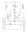
- Figure 4 is a block diagram of functions performed by position/speed control block according to an embodiment of the present invention.
- Figure 5 is a block diagram of a synchronous current regulator with adaptive gains according to an embodiment of the present invention.
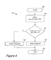
- Figure 6 is a flowchart that illustrates generation of integrator control signals according to an embodiment of the present invention.
- FIG. 1 is a block diagram of control system 10 for an electric actuator 12 according to an embodiment of the present invention.
- Control system 10 includes inverter 14, permanent magnet motor 16, resolver 18, gear transmission 20, valve 21, and controller 22.
- controller 22 includes resolver processing block 24, ABC-to-dq transformation block 26, reference model 28, position speed control block 30, feed forward block 32, field-weakening block 34, synchronous current regulator 36, dq-to-ABC transformation block 38, sine-triangle PWM controller block 40, overcurrent protection block 42, and gate drive block 44.
- valve 21 is translated between an open position (i.e., 90 degrees) and a closed position (i.e., 0 degrees) and includes a return spring that provides a force that must be overcome in translating valve 21 to the open position and that provides a force that assists in translating valve 21 to the closed position.
- Controller 22 controls the position of actuator 12 in response to external command signal pos _ cmd.
- controller 22 acts to regulate the current supplied to PM motor 16 to control the opening/closing of actuator 12 to the commanded position.
- Controller 22 may be implemented by a microprocessor, a digital signal processor, and/or a plurality of discrete devices to implement the functionality illustrated with respect to FIG. 1 .
- Controller 22 also includes a plurality of inputs for monitoring current (e.g., ia ,ib, and ic ) supplied to PM motor 16, and resolver signals related to the position and speed of actuator 12.
- controller 22 is configured to improve the dynamic response of actuator 12 and improve operation of actuator 12 when holding the actuator 12 at a desired position.
- controller 22 employs feed forward block 32 in conjunction with inputs provided by reference model 28 to improve the dynamic response of actuator 12.
- synchronous current regulator block 36 employs adaptive gains based on detected oscillations in the d- and q- axis feedback signals to minimize mechanical oscillations in actuator 12.
- resolver processor block 24 monitors a sine and cosine signal provided by resolver 18. In response, resolver processing block 24 generates an electrical angular position value ⁇ , a position feedback signal pos_fdbk, and a speed feedback signal spd_fdbk. In one embodiment described in more detail with respect to Figure 3 , resolver processing block 24 utilizes a phase lock loop and synchronous sampling algorithm to generate the desired feedback signals. In other embodiments, other well-known means of detecting position and speed of PM motor 16 may be utilized.
- Controller 22 utilizes a field oriented control (FOC) algorithm that converts monitored currents ia, ib and ic from the abc reference frame to the dq reference frame.
- FOC field oriented control
- abc-to-dq transformation block 26 converts the monitored current ia, ib and ic to direct axis and quadrature axis components id_fdbk and iq_fdbk, respectively, based in part on the monitored electrical angular position ⁇ provided by resolver processing block 24.
- the output signals id_fdbk and iq_fdbk provided by abc-to-dq transformation block 26 represents the current provided to PM motor 16.
- the feedback signals id_fdbk and iq_fdbk are compared to commanded signals (i.e., reference signals id_ ref and ig_ref ) as part of a feedback loop to control the operation of inverter 14.
- Reference model 28 generates a position reference signal pos_ref and a speed reference signal spd_ref based on a position command signal pos_cmd received from an external source.
- Reference model 28 defines constraints regarding how quickly valve 21 may be opened or closed by setting velocity and acceleration limits that are reflected in the position reference signal pos_ref and speed reference signal spd_ref.
- Position speed control block 30 compares the position reference signal pos_ref and the speed reference signal spd_ref (which represent the desired position and speed of the motor) with a position feedback signal pos_fdbk and a speed feedback signal spd_fdbk, respectively, to generate a q-axis reference current command iq_ref.
- Position controller 30 calculates a position error signal (not shown) and provides the error to a proportional-integral (PI) controller.
- position controller 30 includes a speed controller with non-linear gain that is used to provide a near-optimal transient response to motor torque disturbances, specifically during spring assist mode.
- Field weakening block 34 generates a d-axis reference current command id_ref based on the monitored speed feedback signal spd_fdbk. In some embodiments, field weakening may not be required, and field weakening block 34 may be omitted.
- the q-axis and d-axis reference signals iq_ref and id_ref , along with the q-axis and d-axis feed forward signals iq_feed and id_feed are provided to synchronous current regulator 36 for comparison with the q-axis and d-axis feedback signals iq_fdbk and id_fdbk.
- synchronous current regulator 36 In response to provided inputs, synchronous current regulator 36 generates a q-axis voltage reference vq_ref and a d-axis voltage reference vd_ref.
- the dq-to-abc transformation block 38 converts the q-axis and d-axis voltage references vq_ref and vd_ref from the dq reference frame to the abc reference frame (e.g., va_ref, vb_ref, and vc_ref ).
- Sine triangle PWM control shoot-through protection block 40 converts the abc reference voltages va_ref, vb_ref, and vc_ ref to pulse width modulation (PWM) signals.
- Gate drive block 44 generates gate drive signals provided to each of the plurality of solid-state devices Q1-Q6 included within inverter 14 to convert the DC input to a desired AC output.
- overcurrent protection block 42 monitors the currents ia, ib, and ic and in response generates an overcurrent signal that is provided to gate drive block 44.
- FIG. 2 is a block diagram of functions performed by the resolver processing block 24 according to an embodiment of the present invention.
- Resolver processing block 24 receives a cosine signal res_cos and sine signal res_sin from resolver 18 (shown in Figure 1 ), and in response generates a position feedback signal pos_fdbk, a speed feedback signal spd _fdbk, and a electrical angular position ⁇ .
- the functions illustrated in FIG. 2 implement a phase-lock loop algorithm, in which the phase ⁇ provided by phase/frequency processor 16 is updated with each sample of the monitored input.
- Resolver processing block 24 may be implemented within controller 22, or may be implemented separate from controller 22, as part of resolver 18. In the latter embodiment, resolver 18 would process the sine and cosine signals internally, and provide controller 22 with an electrical angular position signal ⁇ , a speed feedback signal spd_fdbk, and a position feedback signal pos_ydbk.
- the monitored sine and cosine signals provided by resolver 18 are sampled at the peaks of the excitation signal by the synchronous sampling blocks 50 and 52, respectively. These sampled values are interpreted as the ⁇ reference frame, represented as voltage signals valpha and vbeta.
- Multiplier block 54 multiplies the signal valpha by the sine of the phase-lock loop angle PLL_angle, which represents the most recent phase estimate.
- multiplier block 56 multiplies the signal vbeta by the cosine of the phase-lock look angle PLL_angle.
- Equation 1 is based on the assumption that the sampling rate is great enough that phase advancement between the current phase estimate and the phase of the monitored resolver signals is relatively small (i.e., x ⁇ y).
- the calculated error pll_error between the resolver feedback and the current phase estimate is provided to proportional-integral (PI) controller 60 to generate an output that is representative of the speed monitored by resolver 18.
- the operation of PI controller 60 is tuned via proportional function 62 and integral function 64.
- the error signal pll_error is provided to proportional function 62, and to integrator function 64 with integrator 66, with the output of proportional function 62 and integrator 66 being summed by summer block 68 to implement PI control.
- the output of summer block 68 represents a frequency associated with resolver 18 that is converted to a speed feedback signal by Gr function block 70.
- the output of integrator 66 is likewise provided to integrator 72, which integrates the frequency signal to generate a position estimate referred to as the phase-lock loop angle pll_angle.
- Model reference block 28 generates position and velocity references spd_ref and pos_ref from the input position command pos_cmd to obtain time-optimal trajectories. For example, to open the actuator valve the position command signal pos_cmd may suddenly change from a value of 0 degrees to a value of 90 degrees. However, the mechanical nature of actuator valve 21 dictates that it cannot be instantly opened or closed. Model reference 28 calculates the optimal position and speed reference signals to open/close the actuator valve.
- model reference 28 is employed to implement acceleration and velocity limits associated with the actuator valve opening/closing, and determines the dynamic response and damping associated with the actuator valve.
- Feed forward block supplements the position and speed reference values provided by model reference block 28 by generating feed forward signals to account for particular characteristics of actuator 12 such as the viscosity and spring assisted closing mechanism of actuator 12.
- model reference block 28 receives the position command signal pos_cmd and compares it to the position reference signal pos_ref at comparator block 100.
- the resulting error or difference between the position command signal pas_cmd and the position reference signal pos_ref is compared with a damping value provided by damping block 103, which generates the damping value in response to the speed reference signal spd_ref provided as an output of model reference block 28.
- the error or difference provided by comparator 102 is provided to Kp function block 104, which defines the frequency response of the system.
- the frequency response defined by Kp function block 104 represents the rate at which the PM motor should be accelerated.
- the output of Kp function block 104 represents an acceleration command.
- Acceleration limit block 106 applies an acceleration limit (positive or negative) to the acceleration command provided by Kp function block 104 associated with permanent magnet motor 16.
- Integrator 110 integrates the acceleration command provided by acceleration limit block 106 to define speed reference signal spd_ref which is provided as an output to position speed control block 30.
- speed reference signal spd_ref is provided to feed forward block 32 to generate the q-axis field forward signal vq_feed, and is provided in feedback to damping block 103 and speed limit block 105.
- Damping block 103 includes multiplier block 112, absolute value block 114, Ks function block 116, Kv function block 118 and summer block 120.
- the absolute value of speed reference signal spd_ref is multiplied by the speed reference signal spd_ref to provide the square of the speed reference signal without losing the sign (negative or positive) of the speed reference signal spd_ref
- the output of multiplier block 112 is multiplied by Ks function block 116.
- the Ks function is defined as 1 2 * accel_limit , wherein the term accel_limit is defined by acceleration limit block 106.
- the speed reference signal spd_ref is also multiplied by Kv function block 118.
- speed limit block 105 monitors the speed reference signal spd_ref, and via absolute function block 121 provides the absolute value of the speed reference signal spd_ref to difference block 122 for comparison with speed limit value spd_limit. If the speed reference signal spd_ref is significantly greater than the speed limit value spd_limit, then switch 108 disconnects integrator 110 from the output of acceleration limit block 106, and connects integrator 110 to a value of zero (i.e., ground). In this way, the speed reference signal spd_ref provided by integrator 110 is prevented from increasing beyond a determined speed limit value.
- Hysteresis block 124 prevents toggling of switch 108 when the speed reference signal is near the determined speed limit value.
- the speed reference signal spd_ref is provided to integrator 128, which integrates the speed reference signal to generate a position reference signal pos_ref.
- the position reference signal pos_ref and the speed reference signal spd_ref represent a command vector that is provided to feed forward block 32 and position speed control block 30.
- Feed forward block 32 generates in response to the output vector (speed reference spd_ref and position reference pos_ref ) provided by model reference 28 feed forward signals ( iq_feed and vq_feed ) to account for mechanical aspects of the bias spring and metering valve associated with actuator 12.
- feed forward block 32 is based on the speed reference signal spd_ref and position reference signal pos_ref
- Ke function block 130 generates in response to the speed reference signal spd_ref a q-axis voltage feed forward signal vq_feed.
- Feed forward block also genereates a q-axis feed forward current signal iq_feed based on the speed reference signal spd_ref and position reference signal pos_ref.
- the speed reference signal spd_ref is provided to Kv function block 132, which accounts for the viscous coefficient of the actuator.
- the position reference signal pos_ref is provided to Ks function block 134, which accounts for the spring constant of the actuator.
- the output of Kv function block 132 and Ks function block 134 is summed by summer block 136, which provides the q-axis current feed forward signal iq_feed.
- feed forward block 32 A benefit of feed forward block 32 is the feed forward signals are based on the reference signals (e.g., spd_ref and pos_ref ) provided by model reference block 28, rather than the feedback signals, and therefore are better suited to predict the dynamic response associated with actuator 12.
- reference signals e.g., spd_ref and pos_ref
- Figure 4 is a block diagram of functions performed by position/speed control block 30 according to an embodiment of the present invention.
- reference model block 28 generates in response to a position command signal pos_cmd a position reference signal pos_ref and a speed reference signal spd_ref that represent the desired position and speed of actuator 12.
- Resolver processing block 24 generates in response to cosine and sine waveforms provided by resolver 18 a position feedback signal pos_Jdbk and a speed feedback signal spd_fdbk that represent the actual position and speed of actuator 12.
- Position speed control block 30 compares the desired speed and position signals with the monitored speed and position signals to generate commands used to control the operation of inverter 14 (i.e., to ultimately reduce the error or difference between the desired position and speed values and the monitored position and speed values).
- position speed controller 30 comprises an inner feedback loop that seeks to minimize the difference between the speed reference signal spd_ref and the speed feedback signal spd_fdbk, and an outer feedback loop that seeks to minimize the difference between the position reference signal pos_ref and the position feedback signal pos_fdbk, while taking into account the output of the speed feedback loop.
- Difference block 141 compares the speed reference signal spd_ref with the speed feedback signal spd_fdbk to generate a speed error signal.
- Multiplier block 146 multiplies the speed error signal by the absolute value of the speed error signal provided by absolute value block 147 to generate a squared value of the speed error signal that retains the sign of the error signal (positive or negative).
- the output of multiplier block 146 is applied to Ks function block 148.
- the Ks function is defined as 1 2 * accel_limit , wherein the term accel_lmt is defined by acceleration limit block 106 described with respect to Figure 3 .
- the speed error signal is also multiplied by Kv function block 149.
- the Kv function is defined as 2 ⁇ ⁇ Kp , wherein ⁇ is set equal to a constant value (e.g., 0.7) and Kp function is equal to ⁇ 2 .
- Summer block 150 sums the outputs of Ks function block 148 and Kv function block 149.
- summer block 150 sums the output of Kp function block 144, which indicates the frequency response associated with the error signal generated by difference block 140.
- the output of summer block 150 represents the inner speed feedback loop.
- difference block 140 compares the position reference signal pos_ref with the position feedback signal pos_fdbk to generate a position error signal.
- the output of difference block 140 is provided to Ki function block 142, Kp function block 144, and integrator 143 to provide proportional integral control with respect to the position feedback.
- the output of summer block 150 is summed with the output of integrator block 143 to generate a q-axis reference signal that represents the command signal required to minimize the error between the respective reference signals and feedback signals.
- the q-axis reference signal is applied to limiter block 152 to limit the q-axis current reference signal iq_ref within an acceptable range.
- FIG. 5 is a block diagram of synchronous current regulator 36 with adaptive gains according to an embodiment of the present invention.
- Synchronous current regulator 36 includes dq regulation block 153, q-axis adaptive gain block 154, and d-axis adaptive gain block 155.
- dq regulation block 153 compares the dq reference signals iq_ref and id_ref to feedback signals id_fdbk and iq_fdbk, respectively, and generates in response dq reference signals vq_ref and vd _ ref for provision to dq-to-abc transformation block 38 (shown in Figure 1 ).
- the reference signals vq_re f and vd_ref act to minimize differences between the reference signals and the feedback signals.
- the q-axis reference signal iq_ref is compared with the q-axis feedback signal iq_fdbk at difference block 160 to generate an error signal iq_err.
- the q-axis feed forward signal iq_feed is added to the error signal iq_err by difference block 160.
- the q-axis error signal iq_err is compared with a q-axis adaptive gain output at difference block 162.
- the output of difference block 162 is provided to PI controller 164.
- the output of PI controller 164 is decoupled from the d-axis component by subtracting a decoupling output provided by decoupling block 156 from the output of PI controller 164.
- the q-axis feed forward signal vq_feed is added to the output of PI controller 164 by summer block 166.
- the output of summer block 166 is normalized by dividing the output signals by dc bus voltage vdc at divider block 168.
- Function block 170 applies a function related to the d-axis reference signal vd_ref in order to maintain the q-axis reference voltage vq_ref within stator voltage limitations. In the embodiment shown in Figure 5 , the function is defined as ( 1 - vd_ref 2 .
- the d-axis reference signal id_ref is compared with the d-axis feedback signal id_fdbk by difference block 172 to generate a d-axis error signal id_err.
- the d-axis error signal id_err is compared with the d-axis adaptive gain output at difference block 174.
- the output of difference block 174 is provided to PI controller 176 to generate an output that acts to drive the input provided to PI controller block 176 to zero.
- the output of PI controller 176 is decoupled from the q-axis component at summer block 178.
- a summer block 178 adds a d-axis feed forward signal vd_feed to the output of PI controller block 176.
- the d-axis feed forward signal vd_feed is set equal to zero.
- the output of summer block 178 is divided by the DC bus voltage vdc by divider block 180 to generate the d-axis reference signal vd_ref
- Adaptive gain blocks 154 and 155 act to minimize current loop instability created when the actuator is commanded to be held in a particular position that overlaps motor detent positions.
- adaptive gain blocks 154 and 155 monitor the feedback signals iq_fdbk and id_Jdbk, respectively, for oscillations, and in response to detected oscillations generate an adaptive gain signal that is added to the respective error signals iq_err and id_err.
- the non-zero output provided by integrator 200 is multiplied with the d-axis error signal id_err by multiplier block 202, with the multiplied output being subtracted from the d-axis error signal id_err by difference block 174.
- the method begins at step 212.
- position error signal pos_err and speed feedback signal spd_fdbk are received as inputs by the respective conditions blocks 193 and 193'.
- the position error signal pos_err is compared to a first threshold value ⁇ 1 and the speed feedback signal spd_fdbk is compared to a second threshold value ⁇ 1 . If both the position error signal pos_err and the speed feedback signal spd_fdbk are less than the threshold values, this is indicative that the actuator is being held at a particular position (i.e., is no longer moving from a first position to a second position), and integrator 192 is enabled at step 218. If either the position error signal pos_err or the speed feedback signal spd_fdbk is not less than the respective threshold values then integrator 192 is reset at step 221. At step 222, the method ends.
Landscapes
- Engineering & Computer Science (AREA)
- Power Engineering (AREA)
- Physics & Mathematics (AREA)
- General Physics & Mathematics (AREA)
- Automation & Control Theory (AREA)
- Control Of Ac Motors In General (AREA)
- Control Of Electric Motors In General (AREA)
- Feedback Control In General (AREA)
- Control Of Position Or Direction (AREA)
Applications Claiming Priority (1)
| Application Number | Priority Date | Filing Date | Title |
|---|---|---|---|
| US13/475,209 US8729838B2 (en) | 2012-05-18 | 2012-05-18 | Current control for an electric actuator |
Publications (3)
| Publication Number | Publication Date |
|---|---|
| EP2665175A2 true EP2665175A2 (de) | 2013-11-20 |
| EP2665175A3 EP2665175A3 (de) | 2017-08-16 |
| EP2665175B1 EP2665175B1 (de) | 2020-07-22 |
Family
ID=48470777
Family Applications (1)
| Application Number | Title | Priority Date | Filing Date |
|---|---|---|---|
| EP13168461.5A Active EP2665175B1 (de) | 2012-05-18 | 2013-05-20 | Stromregelung für einen elektrischen Aktuator |
Country Status (3)
| Country | Link |
|---|---|
| US (1) | US8729838B2 (de) |
| EP (1) | EP2665175B1 (de) |
| CN (1) | CN103427750B (de) |
Families Citing this family (15)
| Publication number | Priority date | Publication date | Assignee | Title |
|---|---|---|---|---|
| DE112012005678T5 (de) * | 2012-01-16 | 2014-10-23 | Mitsubishi Electric Corporation | Motorsteuervorrichtung |
| US9071172B2 (en) * | 2013-03-14 | 2015-06-30 | Microchip Technology Incorporated | Sine modified trapezoidal drive for brushless DC motors |
| JP6137086B2 (ja) * | 2014-08-19 | 2017-05-31 | 株式会社デンソー | 回転電機制御装置 |
| US9385647B2 (en) * | 2014-08-20 | 2016-07-05 | Hamilton Sundstrand Corporation | Reduction technique for permanent magnet motor high frequency loss |
| US9958838B2 (en) | 2014-10-23 | 2018-05-01 | Halliburton Energy Services, Inc. | Optimizing power delivered to an electrical actuator |
| US9450520B2 (en) * | 2014-12-15 | 2016-09-20 | Analog Devices, Inc. | Space vector pulse modulation based motor driver |
| JP6005781B2 (ja) * | 2015-03-05 | 2016-10-12 | 日本航空電子工業株式会社 | レゾルバ装置 |
| US9909442B2 (en) * | 2015-07-02 | 2018-03-06 | General Electric Company | Method of controlling a position actuation system component for a gas turbine engine |
| US10447180B2 (en) | 2016-01-12 | 2019-10-15 | Hamilton Sundstrand Space Systems International, Inc. | Control of large electromechanical actuators |
| US10333455B2 (en) * | 2016-03-30 | 2019-06-25 | Eaton Intelligent Power Limited | System and method for consistent speed regulation in a variable frequency drive |
| JP7073620B2 (ja) * | 2016-10-31 | 2022-05-24 | ヤマハ株式会社 | アクチュエータの駆動制御装置 |
| WO2019146437A1 (ja) * | 2018-01-25 | 2019-08-01 | 株式会社豊田自動織機 | インバータ装置 |
| US20210391812A1 (en) * | 2020-06-12 | 2021-12-16 | Saginaw Valley State University | Position sensor offset error diagnosis and calibration in permanent magnet synchronous machine |
| WO2023148326A1 (en) * | 2022-02-04 | 2023-08-10 | Asml Netherlands B.V. | Lithographic apparatus controller system |
| CN119483378A (zh) * | 2024-11-18 | 2025-02-18 | 清华大学 | 基于频域分析的永磁同步电机控制参数自整定方法及系统 |
Family Cites Families (11)
| Publication number | Priority date | Publication date | Assignee | Title |
|---|---|---|---|---|
| US5233512A (en) | 1990-06-21 | 1993-08-03 | General Electric Company | Method and apparatus for actuator fault detection |
| US6249100B1 (en) | 1997-07-31 | 2001-06-19 | Honeywell International Inc. | Drive circuit and method for an electric actuator with spring return |
| JP3928575B2 (ja) * | 2003-04-07 | 2007-06-13 | 日産自動車株式会社 | モーター制御装置 |
| US7336509B2 (en) * | 2005-09-28 | 2008-02-26 | Rockwell Automation Technologies, Inc. | Method and apparatus for estimating line inductance for PWM rectifier control |
| US7282886B1 (en) * | 2006-08-04 | 2007-10-16 | Gm Global Technology Operations, Inc. | Method and system for controlling permanent magnet motor drive systems |
| US7733051B2 (en) * | 2006-11-21 | 2010-06-08 | Asm Assembly Automation Ltd. | Model-based active electronic damping for stepper motors |
| JP4466882B2 (ja) * | 2007-08-03 | 2010-05-26 | 本田技研工業株式会社 | 電動機の制御装置 |
| JP2009303432A (ja) * | 2008-06-17 | 2009-12-24 | Hitachi Industrial Equipment Systems Co Ltd | モータによる位置制御装置 |
| JP5512954B2 (ja) * | 2008-10-31 | 2014-06-04 | オークマ株式会社 | 数値制御機械の位置制御装置 |
| TW201230657A (en) * | 2010-10-08 | 2012-07-16 | Panasonic Corp | Current control gain adjusting method for pm motor, current control method, and control device |
| CN101977009B (zh) * | 2010-10-09 | 2013-01-02 | 江苏中容电气有限公司 | 高精度数控机床进给驱动用正弦波直线电机的控制方法 |
-
2012
- 2012-05-18 US US13/475,209 patent/US8729838B2/en active Active
-
2013
- 2013-05-15 CN CN201310179118.0A patent/CN103427750B/zh active Active
- 2013-05-20 EP EP13168461.5A patent/EP2665175B1/de active Active
Non-Patent Citations (1)
| Title |
|---|
| None |
Also Published As
| Publication number | Publication date |
|---|---|
| EP2665175A3 (de) | 2017-08-16 |
| CN103427750B (zh) | 2017-08-04 |
| EP2665175B1 (de) | 2020-07-22 |
| US8729838B2 (en) | 2014-05-20 |
| US20130307447A1 (en) | 2013-11-21 |
| CN103427750A (zh) | 2013-12-04 |
Similar Documents
| Publication | Publication Date | Title |
|---|---|---|
| US8729838B2 (en) | Current control for an electric actuator | |
| Sreejith et al. | Sensorless predictive control of SPMSM-driven light EV drive using modified speed adaptive super twisting sliding mode observer with MAF-PLL | |
| US7622877B2 (en) | Method and system for controlling permanent magnet AC machines | |
| US7642737B2 (en) | Anti-windup control for a current regulator of a pulse width modulation inverter | |
| CN104620497B (zh) | 逆变器控制装置以及逆变器控制方法 | |
| US8928265B2 (en) | Sensorless field-oriented control (FOC) without current sampling for motors | |
| US11711039B2 (en) | Motor drive apparatus | |
| JP4797074B2 (ja) | 永久磁石モータのベクトル制御装置、永久磁石モータのベクトル制御システム、及びスクリュー圧縮器 | |
| EP2963804B1 (de) | Wechselrichter, baumaschine und motorsteuerungsverfahren | |
| Maric et al. | Two flux weakening schemes for surface-mounted permanent-magnet synchronous drives. Design and transient response considerations | |
| CN114765438A (zh) | 线性时变模型预测转矩控制 | |
| Kumar et al. | Sliding mode observer based rotor position estimation with field oriented control of PMBLDC motor drive | |
| US12126284B2 (en) | Electric motor control method and electric motor system | |
| JP2023170542A (ja) | 回転電機の制御方法、及び、回転電機の制御装置 | |
| JP2004248450A (ja) | 電力変換装置 | |
| Ammar et al. | Implementation of sliding mode based-direct flux and torque control for induction motor drive with efficiency optimization | |
| Kakodia et al. | Reduced Position Error and Overshoot Control Using Modified Integrator-Based QPR Controller and SMO for Limp Home Mode PMSM-driven EV | |
| JP2006217762A (ja) | 交流電動機駆動装置 | |
| Mirzaeva et al. | High performance control of power converters in industrial AC drive applications | |
| JP7767969B2 (ja) | 巻線界磁型回転電機の制御方法、及び、巻線界磁型回転電機の制御装置 | |
| JP3793919B2 (ja) | 誘導電動機の制御方法 | |
| Wang et al. | Adaptive Dividing Factor and Reference Voltage Overmodulation Strategy for PMSM Field-Weakening Control | |
| JP2013188074A (ja) | 誘導モータの制御装置および制御方法 | |
| Ahmad et al. | of Three-Phase Induction Motor Using Sliding Mode Controller and Rotor Flux | |
| CN120898361A (zh) | 功率调节器 |
Legal Events
| Date | Code | Title | Description |
|---|---|---|---|
| PUAI | Public reference made under article 153(3) epc to a published international application that has entered the european phase |
Free format text: ORIGINAL CODE: 0009012 |
|
| AK | Designated contracting states |
Kind code of ref document: A2 Designated state(s): AL AT BE BG CH CY CZ DE DK EE ES FI FR GB GR HR HU IE IS IT LI LT LU LV MC MK MT NL NO PL PT RO RS SE SI SK SM TR |
|
| AX | Request for extension of the european patent |
Extension state: BA ME |
|
| PUAL | Search report despatched |
Free format text: ORIGINAL CODE: 0009013 |
|
| AK | Designated contracting states |
Kind code of ref document: A3 Designated state(s): AL AT BE BG CH CY CZ DE DK EE ES FI FR GB GR HR HU IE IS IT LI LT LU LV MC MK MT NL NO PL PT RO RS SE SI SK SM TR |
|
| AX | Request for extension of the european patent |
Extension state: BA ME |
|
| RIC1 | Information provided on ipc code assigned before grant |
Ipc: G05B 11/01 20060101AFI20170712BHEP Ipc: H02P 21/00 20160101ALN20170712BHEP |
|
| STAA | Information on the status of an ep patent application or granted ep patent |
Free format text: STATUS: REQUEST FOR EXAMINATION WAS MADE |
|
| 17P | Request for examination filed |
Effective date: 20180215 |
|
| RBV | Designated contracting states (corrected) |
Designated state(s): AL AT BE BG CH CY CZ DE DK EE ES FI FR GB GR HR HU IE IS IT LI LT LU LV MC MK MT NL NO PL PT RO RS SE SI SK SM TR |
|
| REG | Reference to a national code |
Ref country code: DE Ref legal event code: R079 Ref document number: 602013070856 Country of ref document: DE Free format text: PREVIOUS MAIN CLASS: H02P0006160000 Ipc: G05B0011010000 |
|
| GRAP | Despatch of communication of intention to grant a patent |
Free format text: ORIGINAL CODE: EPIDOSNIGR1 |
|
| STAA | Information on the status of an ep patent application or granted ep patent |
Free format text: STATUS: GRANT OF PATENT IS INTENDED |
|
| RIC1 | Information provided on ipc code assigned before grant |
Ipc: H02P 6/34 20160101ALI20200212BHEP Ipc: G05B 11/01 20060101AFI20200212BHEP Ipc: H02P 21/00 20160101ALN20200212BHEP Ipc: H02P 21/22 20160101ALI20200212BHEP Ipc: H02P 6/17 20160101ALI20200212BHEP |
|
| INTG | Intention to grant announced |
Effective date: 20200302 |
|
| GRAS | Grant fee paid |
Free format text: ORIGINAL CODE: EPIDOSNIGR3 |
|
| GRAA | (expected) grant |
Free format text: ORIGINAL CODE: 0009210 |
|
| STAA | Information on the status of an ep patent application or granted ep patent |
Free format text: STATUS: THE PATENT HAS BEEN GRANTED |
|
| AK | Designated contracting states |
Kind code of ref document: B1 Designated state(s): AL AT BE BG CH CY CZ DE DK EE ES FI FR GB GR HR HU IE IS IT LI LT LU LV MC MK MT NL NO PL PT RO RS SE SI SK SM TR |
|
| RAP1 | Party data changed (applicant data changed or rights of an application transferred) |
Owner name: HAMILTON SUNDSTRAND CORPORATION |
|
| REG | Reference to a national code |
Ref country code: GB Ref legal event code: FG4D |
|
| REG | Reference to a national code |
Ref country code: CH Ref legal event code: EP |
|
| REG | Reference to a national code |
Ref country code: DE Ref legal event code: R096 Ref document number: 602013070856 Country of ref document: DE |
|
| REG | Reference to a national code |
Ref country code: AT Ref legal event code: REF Ref document number: 1293988 Country of ref document: AT Kind code of ref document: T Effective date: 20200815 |
|
| REG | Reference to a national code |
Ref country code: IE Ref legal event code: FG4D |
|
| REG | Reference to a national code |
Ref country code: LT Ref legal event code: MG4D |
|
| REG | Reference to a national code |
Ref country code: AT Ref legal event code: MK05 Ref document number: 1293988 Country of ref document: AT Kind code of ref document: T Effective date: 20200722 |
|
| PG25 | Lapsed in a contracting state [announced via postgrant information from national office to epo] |
Ref country code: AT Free format text: LAPSE BECAUSE OF FAILURE TO SUBMIT A TRANSLATION OF THE DESCRIPTION OR TO PAY THE FEE WITHIN THE PRESCRIBED TIME-LIMIT Effective date: 20200722 Ref country code: GR Free format text: LAPSE BECAUSE OF FAILURE TO SUBMIT A TRANSLATION OF THE DESCRIPTION OR TO PAY THE FEE WITHIN THE PRESCRIBED TIME-LIMIT Effective date: 20201023 Ref country code: HR Free format text: LAPSE BECAUSE OF FAILURE TO SUBMIT A TRANSLATION OF THE DESCRIPTION OR TO PAY THE FEE WITHIN THE PRESCRIBED TIME-LIMIT Effective date: 20200722 Ref country code: NO Free format text: LAPSE BECAUSE OF FAILURE TO SUBMIT A TRANSLATION OF THE DESCRIPTION OR TO PAY THE FEE WITHIN THE PRESCRIBED TIME-LIMIT Effective date: 20201022 Ref country code: ES Free format text: LAPSE BECAUSE OF FAILURE TO SUBMIT A TRANSLATION OF THE DESCRIPTION OR TO PAY THE FEE WITHIN THE PRESCRIBED TIME-LIMIT Effective date: 20200722 Ref country code: LT Free format text: LAPSE BECAUSE OF FAILURE TO SUBMIT A TRANSLATION OF THE DESCRIPTION OR TO PAY THE FEE WITHIN THE PRESCRIBED TIME-LIMIT Effective date: 20200722 Ref country code: BG Free format text: LAPSE BECAUSE OF FAILURE TO SUBMIT A TRANSLATION OF THE DESCRIPTION OR TO PAY THE FEE WITHIN THE PRESCRIBED TIME-LIMIT Effective date: 20201022 Ref country code: PT Free format text: LAPSE BECAUSE OF FAILURE TO SUBMIT A TRANSLATION OF THE DESCRIPTION OR TO PAY THE FEE WITHIN THE PRESCRIBED TIME-LIMIT Effective date: 20201123 Ref country code: FI Free format text: LAPSE BECAUSE OF FAILURE TO SUBMIT A TRANSLATION OF THE DESCRIPTION OR TO PAY THE FEE WITHIN THE PRESCRIBED TIME-LIMIT Effective date: 20200722 Ref country code: SE Free format text: LAPSE BECAUSE OF FAILURE TO SUBMIT A TRANSLATION OF THE DESCRIPTION OR TO PAY THE FEE WITHIN THE PRESCRIBED TIME-LIMIT Effective date: 20200722 |
|
| PG25 | Lapsed in a contracting state [announced via postgrant information from national office to epo] |
Ref country code: LV Free format text: LAPSE BECAUSE OF FAILURE TO SUBMIT A TRANSLATION OF THE DESCRIPTION OR TO PAY THE FEE WITHIN THE PRESCRIBED TIME-LIMIT Effective date: 20200722 Ref country code: RS Free format text: LAPSE BECAUSE OF FAILURE TO SUBMIT A TRANSLATION OF THE DESCRIPTION OR TO PAY THE FEE WITHIN THE PRESCRIBED TIME-LIMIT Effective date: 20200722 Ref country code: PL Free format text: LAPSE BECAUSE OF FAILURE TO SUBMIT A TRANSLATION OF THE DESCRIPTION OR TO PAY THE FEE WITHIN THE PRESCRIBED TIME-LIMIT Effective date: 20200722 Ref country code: IS Free format text: LAPSE BECAUSE OF FAILURE TO SUBMIT A TRANSLATION OF THE DESCRIPTION OR TO PAY THE FEE WITHIN THE PRESCRIBED TIME-LIMIT Effective date: 20201122 |
|
| PG25 | Lapsed in a contracting state [announced via postgrant information from national office to epo] |
Ref country code: NL Free format text: LAPSE BECAUSE OF FAILURE TO SUBMIT A TRANSLATION OF THE DESCRIPTION OR TO PAY THE FEE WITHIN THE PRESCRIBED TIME-LIMIT Effective date: 20200722 |
|
| REG | Reference to a national code |
Ref country code: DE Ref legal event code: R097 Ref document number: 602013070856 Country of ref document: DE |
|
| PG25 | Lapsed in a contracting state [announced via postgrant information from national office to epo] |
Ref country code: DK Free format text: LAPSE BECAUSE OF FAILURE TO SUBMIT A TRANSLATION OF THE DESCRIPTION OR TO PAY THE FEE WITHIN THE PRESCRIBED TIME-LIMIT Effective date: 20200722 Ref country code: EE Free format text: LAPSE BECAUSE OF FAILURE TO SUBMIT A TRANSLATION OF THE DESCRIPTION OR TO PAY THE FEE WITHIN THE PRESCRIBED TIME-LIMIT Effective date: 20200722 Ref country code: CZ Free format text: LAPSE BECAUSE OF FAILURE TO SUBMIT A TRANSLATION OF THE DESCRIPTION OR TO PAY THE FEE WITHIN THE PRESCRIBED TIME-LIMIT Effective date: 20200722 Ref country code: IT Free format text: LAPSE BECAUSE OF FAILURE TO SUBMIT A TRANSLATION OF THE DESCRIPTION OR TO PAY THE FEE WITHIN THE PRESCRIBED TIME-LIMIT Effective date: 20200722 Ref country code: SM Free format text: LAPSE BECAUSE OF FAILURE TO SUBMIT A TRANSLATION OF THE DESCRIPTION OR TO PAY THE FEE WITHIN THE PRESCRIBED TIME-LIMIT Effective date: 20200722 Ref country code: RO Free format text: LAPSE BECAUSE OF FAILURE TO SUBMIT A TRANSLATION OF THE DESCRIPTION OR TO PAY THE FEE WITHIN THE PRESCRIBED TIME-LIMIT Effective date: 20200722 |
|
| PLBE | No opposition filed within time limit |
Free format text: ORIGINAL CODE: 0009261 |
|
| STAA | Information on the status of an ep patent application or granted ep patent |
Free format text: STATUS: NO OPPOSITION FILED WITHIN TIME LIMIT |
|
| PG25 | Lapsed in a contracting state [announced via postgrant information from national office to epo] |
Ref country code: AL Free format text: LAPSE BECAUSE OF FAILURE TO SUBMIT A TRANSLATION OF THE DESCRIPTION OR TO PAY THE FEE WITHIN THE PRESCRIBED TIME-LIMIT Effective date: 20200722 |
|
| 26N | No opposition filed |
Effective date: 20210423 |
|
| PG25 | Lapsed in a contracting state [announced via postgrant information from national office to epo] |
Ref country code: SK Free format text: LAPSE BECAUSE OF FAILURE TO SUBMIT A TRANSLATION OF THE DESCRIPTION OR TO PAY THE FEE WITHIN THE PRESCRIBED TIME-LIMIT Effective date: 20200722 |
|
| PG25 | Lapsed in a contracting state [announced via postgrant information from national office to epo] |
Ref country code: SI Free format text: LAPSE BECAUSE OF FAILURE TO SUBMIT A TRANSLATION OF THE DESCRIPTION OR TO PAY THE FEE WITHIN THE PRESCRIBED TIME-LIMIT Effective date: 20200722 |
|
| REG | Reference to a national code |
Ref country code: NL Ref legal event code: MP Effective date: 20200722 |
|
| REG | Reference to a national code |
Ref country code: CH Ref legal event code: PL |
|
| PG25 | Lapsed in a contracting state [announced via postgrant information from national office to epo] |
Ref country code: LI Free format text: LAPSE BECAUSE OF NON-PAYMENT OF DUE FEES Effective date: 20210531 Ref country code: LU Free format text: LAPSE BECAUSE OF NON-PAYMENT OF DUE FEES Effective date: 20210520 Ref country code: MC Free format text: LAPSE BECAUSE OF FAILURE TO SUBMIT A TRANSLATION OF THE DESCRIPTION OR TO PAY THE FEE WITHIN THE PRESCRIBED TIME-LIMIT Effective date: 20200722 Ref country code: CH Free format text: LAPSE BECAUSE OF NON-PAYMENT OF DUE FEES Effective date: 20210531 |
|
| REG | Reference to a national code |
Ref country code: BE Ref legal event code: MM Effective date: 20210531 |
|
| PG25 | Lapsed in a contracting state [announced via postgrant information from national office to epo] |
Ref country code: IE Free format text: LAPSE BECAUSE OF NON-PAYMENT OF DUE FEES Effective date: 20210520 |
|
| PG25 | Lapsed in a contracting state [announced via postgrant information from national office to epo] |
Ref country code: BE Free format text: LAPSE BECAUSE OF NON-PAYMENT OF DUE FEES Effective date: 20210531 |
|
| PG25 | Lapsed in a contracting state [announced via postgrant information from national office to epo] |
Ref country code: HU Free format text: LAPSE BECAUSE OF FAILURE TO SUBMIT A TRANSLATION OF THE DESCRIPTION OR TO PAY THE FEE WITHIN THE PRESCRIBED TIME-LIMIT; INVALID AB INITIO Effective date: 20130520 |
|
| P01 | Opt-out of the competence of the unified patent court (upc) registered |
Effective date: 20230522 |
|
| PG25 | Lapsed in a contracting state [announced via postgrant information from national office to epo] |
Ref country code: CY Free format text: LAPSE BECAUSE OF FAILURE TO SUBMIT A TRANSLATION OF THE DESCRIPTION OR TO PAY THE FEE WITHIN THE PRESCRIBED TIME-LIMIT Effective date: 20200722 |
|
| PG25 | Lapsed in a contracting state [announced via postgrant information from national office to epo] |
Ref country code: MK Free format text: LAPSE BECAUSE OF FAILURE TO SUBMIT A TRANSLATION OF THE DESCRIPTION OR TO PAY THE FEE WITHIN THE PRESCRIBED TIME-LIMIT Effective date: 20200722 |
|
| PG25 | Lapsed in a contracting state [announced via postgrant information from national office to epo] |
Ref country code: MT Free format text: LAPSE BECAUSE OF FAILURE TO SUBMIT A TRANSLATION OF THE DESCRIPTION OR TO PAY THE FEE WITHIN THE PRESCRIBED TIME-LIMIT Effective date: 20200722 |
|
| PGFP | Annual fee paid to national office [announced via postgrant information from national office to epo] |
Ref country code: DE Payment date: 20250423 Year of fee payment: 13 |
|
| PGFP | Annual fee paid to national office [announced via postgrant information from national office to epo] |
Ref country code: GB Payment date: 20250423 Year of fee payment: 13 |
|
| PGFP | Annual fee paid to national office [announced via postgrant information from national office to epo] |
Ref country code: FR Payment date: 20250423 Year of fee payment: 13 |
|
| PG25 | Lapsed in a contracting state [announced via postgrant information from national office to epo] |
Ref country code: TR Free format text: LAPSE BECAUSE OF FAILURE TO SUBMIT A TRANSLATION OF THE DESCRIPTION OR TO PAY THE FEE WITHIN THE PRESCRIBED TIME-LIMIT Effective date: 20200722 |