EP2665160A1 - Device for transmitting driving force of motors - Google Patents
Device for transmitting driving force of motors Download PDFInfo
- Publication number
- EP2665160A1 EP2665160A1 EP12734585.8A EP12734585A EP2665160A1 EP 2665160 A1 EP2665160 A1 EP 2665160A1 EP 12734585 A EP12734585 A EP 12734585A EP 2665160 A1 EP2665160 A1 EP 2665160A1
- Authority
- EP
- European Patent Office
- Prior art keywords
- driving force
- electric motor
- motor driving
- speed reduction
- transmission device
- Prior art date
- Legal status (The legal status is an assumption and is not a legal conclusion. Google has not performed a legal analysis and makes no representation as to the accuracy of the status listed.)
- Withdrawn
Links
Images




Classifications
-
- F—MECHANICAL ENGINEERING; LIGHTING; HEATING; WEAPONS; BLASTING
- F16—ENGINEERING ELEMENTS AND UNITS; GENERAL MEASURES FOR PRODUCING AND MAINTAINING EFFECTIVE FUNCTIONING OF MACHINES OR INSTALLATIONS; THERMAL INSULATION IN GENERAL
- F16H—GEARING
- F16H48/00—Differential gearings
- F16H48/20—Arrangements for suppressing or influencing the differential action, e.g. locking devices
-
- B—PERFORMING OPERATIONS; TRANSPORTING
- B60—VEHICLES IN GENERAL
- B60K—ARRANGEMENT OR MOUNTING OF PROPULSION UNITS OR OF TRANSMISSIONS IN VEHICLES; ARRANGEMENT OR MOUNTING OF PLURAL DIVERSE PRIME-MOVERS IN VEHICLES; AUXILIARY DRIVES FOR VEHICLES; INSTRUMENTATION OR DASHBOARDS FOR VEHICLES; ARRANGEMENTS IN CONNECTION WITH COOLING, AIR INTAKE, GAS EXHAUST OR FUEL SUPPLY OF PROPULSION UNITS IN VEHICLES
- B60K1/00—Arrangement or mounting of electrical propulsion units
- B60K1/02—Arrangement or mounting of electrical propulsion units comprising more than one electric motor
-
- B—PERFORMING OPERATIONS; TRANSPORTING
- B60—VEHICLES IN GENERAL
- B60K—ARRANGEMENT OR MOUNTING OF PROPULSION UNITS OR OF TRANSMISSIONS IN VEHICLES; ARRANGEMENT OR MOUNTING OF PLURAL DIVERSE PRIME-MOVERS IN VEHICLES; AUXILIARY DRIVES FOR VEHICLES; INSTRUMENTATION OR DASHBOARDS FOR VEHICLES; ARRANGEMENTS IN CONNECTION WITH COOLING, AIR INTAKE, GAS EXHAUST OR FUEL SUPPLY OF PROPULSION UNITS IN VEHICLES
- B60K17/00—Arrangement or mounting of transmissions in vehicles
- B60K17/34—Arrangement or mounting of transmissions in vehicles for driving both front and rear wheels, e.g. four wheel drive vehicles
- B60K17/356—Arrangement or mounting of transmissions in vehicles for driving both front and rear wheels, e.g. four wheel drive vehicles having fluid or electric motor, for driving one or more wheels
-
- B—PERFORMING OPERATIONS; TRANSPORTING
- B60—VEHICLES IN GENERAL
- B60K—ARRANGEMENT OR MOUNTING OF PROPULSION UNITS OR OF TRANSMISSIONS IN VEHICLES; ARRANGEMENT OR MOUNTING OF PLURAL DIVERSE PRIME-MOVERS IN VEHICLES; AUXILIARY DRIVES FOR VEHICLES; INSTRUMENTATION OR DASHBOARDS FOR VEHICLES; ARRANGEMENTS IN CONNECTION WITH COOLING, AIR INTAKE, GAS EXHAUST OR FUEL SUPPLY OF PROPULSION UNITS IN VEHICLES
- B60K6/00—Arrangement or mounting of plural diverse prime-movers for mutual or common propulsion, e.g. hybrid propulsion systems comprising electric motors and internal combustion engines
- B60K6/20—Arrangement or mounting of plural diverse prime-movers for mutual or common propulsion, e.g. hybrid propulsion systems comprising electric motors and internal combustion engines the prime-movers consisting of electric motors and internal combustion engines, e.g. HEVs
- B60K6/22—Arrangement or mounting of plural diverse prime-movers for mutual or common propulsion, e.g. hybrid propulsion systems comprising electric motors and internal combustion engines the prime-movers consisting of electric motors and internal combustion engines, e.g. HEVs characterised by apparatus, components or means specially adapted for HEVs
- B60K6/36—Arrangement or mounting of plural diverse prime-movers for mutual or common propulsion, e.g. hybrid propulsion systems comprising electric motors and internal combustion engines the prime-movers consisting of electric motors and internal combustion engines, e.g. HEVs characterised by apparatus, components or means specially adapted for HEVs characterised by the transmission gearings
- B60K6/365—Arrangement or mounting of plural diverse prime-movers for mutual or common propulsion, e.g. hybrid propulsion systems comprising electric motors and internal combustion engines the prime-movers consisting of electric motors and internal combustion engines, e.g. HEVs characterised by apparatus, components or means specially adapted for HEVs characterised by the transmission gearings with the gears having orbital motion
-
- B—PERFORMING OPERATIONS; TRANSPORTING
- B60—VEHICLES IN GENERAL
- B60K—ARRANGEMENT OR MOUNTING OF PROPULSION UNITS OR OF TRANSMISSIONS IN VEHICLES; ARRANGEMENT OR MOUNTING OF PLURAL DIVERSE PRIME-MOVERS IN VEHICLES; AUXILIARY DRIVES FOR VEHICLES; INSTRUMENTATION OR DASHBOARDS FOR VEHICLES; ARRANGEMENTS IN CONNECTION WITH COOLING, AIR INTAKE, GAS EXHAUST OR FUEL SUPPLY OF PROPULSION UNITS IN VEHICLES
- B60K6/00—Arrangement or mounting of plural diverse prime-movers for mutual or common propulsion, e.g. hybrid propulsion systems comprising electric motors and internal combustion engines
- B60K6/20—Arrangement or mounting of plural diverse prime-movers for mutual or common propulsion, e.g. hybrid propulsion systems comprising electric motors and internal combustion engines the prime-movers consisting of electric motors and internal combustion engines, e.g. HEVs
- B60K6/50—Architecture of the driveline characterised by arrangement or kind of transmission units
- B60K6/52—Driving a plurality of drive axles, e.g. four-wheel drive
-
- B—PERFORMING OPERATIONS; TRANSPORTING
- B60—VEHICLES IN GENERAL
- B60K—ARRANGEMENT OR MOUNTING OF PROPULSION UNITS OR OF TRANSMISSIONS IN VEHICLES; ARRANGEMENT OR MOUNTING OF PLURAL DIVERSE PRIME-MOVERS IN VEHICLES; AUXILIARY DRIVES FOR VEHICLES; INSTRUMENTATION OR DASHBOARDS FOR VEHICLES; ARRANGEMENTS IN CONNECTION WITH COOLING, AIR INTAKE, GAS EXHAUST OR FUEL SUPPLY OF PROPULSION UNITS IN VEHICLES
- B60K7/00—Disposition of motor in, or adjacent to, traction wheel
- B60K7/0007—Disposition of motor in, or adjacent to, traction wheel the motor being electric
-
- B—PERFORMING OPERATIONS; TRANSPORTING
- B60—VEHICLES IN GENERAL
- B60L—PROPULSION OF ELECTRICALLY-PROPELLED VEHICLES; SUPPLYING ELECTRIC POWER FOR AUXILIARY EQUIPMENT OF ELECTRICALLY-PROPELLED VEHICLES; ELECTRODYNAMIC BRAKE SYSTEMS FOR VEHICLES IN GENERAL; MAGNETIC SUSPENSION OR LEVITATION FOR VEHICLES; MONITORING OPERATING VARIABLES OF ELECTRICALLY-PROPELLED VEHICLES; ELECTRIC SAFETY DEVICES FOR ELECTRICALLY-PROPELLED VEHICLES
- B60L15/00—Methods, circuits, or devices for controlling the traction-motor speed of electrically-propelled vehicles
- B60L15/20—Methods, circuits, or devices for controlling the traction-motor speed of electrically-propelled vehicles for control of the vehicle or its driving motor to achieve a desired performance, e.g. speed, torque, programmed variation of speed
-
- B—PERFORMING OPERATIONS; TRANSPORTING
- B60—VEHICLES IN GENERAL
- B60L—PROPULSION OF ELECTRICALLY-PROPELLED VEHICLES; SUPPLYING ELECTRIC POWER FOR AUXILIARY EQUIPMENT OF ELECTRICALLY-PROPELLED VEHICLES; ELECTRODYNAMIC BRAKE SYSTEMS FOR VEHICLES IN GENERAL; MAGNETIC SUSPENSION OR LEVITATION FOR VEHICLES; MONITORING OPERATING VARIABLES OF ELECTRICALLY-PROPELLED VEHICLES; ELECTRIC SAFETY DEVICES FOR ELECTRICALLY-PROPELLED VEHICLES
- B60L3/00—Electric devices on electrically-propelled vehicles for safety purposes; Monitoring operating variables, e.g. speed, deceleration or energy consumption
- B60L3/0023—Detecting, eliminating, remedying or compensating for drive train abnormalities, e.g. failures within the drive train
- B60L3/0061—Detecting, eliminating, remedying or compensating for drive train abnormalities, e.g. failures within the drive train relating to electrical machines
-
- B—PERFORMING OPERATIONS; TRANSPORTING
- B60—VEHICLES IN GENERAL
- B60L—PROPULSION OF ELECTRICALLY-PROPELLED VEHICLES; SUPPLYING ELECTRIC POWER FOR AUXILIARY EQUIPMENT OF ELECTRICALLY-PROPELLED VEHICLES; ELECTRODYNAMIC BRAKE SYSTEMS FOR VEHICLES IN GENERAL; MAGNETIC SUSPENSION OR LEVITATION FOR VEHICLES; MONITORING OPERATING VARIABLES OF ELECTRICALLY-PROPELLED VEHICLES; ELECTRIC SAFETY DEVICES FOR ELECTRICALLY-PROPELLED VEHICLES
- B60L50/00—Electric propulsion with power supplied within the vehicle
- B60L50/10—Electric propulsion with power supplied within the vehicle using propulsion power supplied by engine-driven generators, e.g. generators driven by combustion engines
- B60L50/16—Electric propulsion with power supplied within the vehicle using propulsion power supplied by engine-driven generators, e.g. generators driven by combustion engines with provision for separate direct mechanical propulsion
-
- B—PERFORMING OPERATIONS; TRANSPORTING
- B60—VEHICLES IN GENERAL
- B60L—PROPULSION OF ELECTRICALLY-PROPELLED VEHICLES; SUPPLYING ELECTRIC POWER FOR AUXILIARY EQUIPMENT OF ELECTRICALLY-PROPELLED VEHICLES; ELECTRODYNAMIC BRAKE SYSTEMS FOR VEHICLES IN GENERAL; MAGNETIC SUSPENSION OR LEVITATION FOR VEHICLES; MONITORING OPERATING VARIABLES OF ELECTRICALLY-PROPELLED VEHICLES; ELECTRIC SAFETY DEVICES FOR ELECTRICALLY-PROPELLED VEHICLES
- B60L50/00—Electric propulsion with power supplied within the vehicle
- B60L50/50—Electric propulsion with power supplied within the vehicle using propulsion power supplied by batteries or fuel cells
- B60L50/60—Electric propulsion with power supplied within the vehicle using propulsion power supplied by batteries or fuel cells using power supplied by batteries
- B60L50/61—Electric propulsion with power supplied within the vehicle using propulsion power supplied by batteries or fuel cells using power supplied by batteries by batteries charged by engine-driven generators, e.g. series hybrid electric vehicles
-
- B—PERFORMING OPERATIONS; TRANSPORTING
- B60—VEHICLES IN GENERAL
- B60W—CONJOINT CONTROL OF VEHICLE SUB-UNITS OF DIFFERENT TYPE OR DIFFERENT FUNCTION; CONTROL SYSTEMS SPECIALLY ADAPTED FOR HYBRID VEHICLES; ROAD VEHICLE DRIVE CONTROL SYSTEMS FOR PURPOSES NOT RELATED TO THE CONTROL OF A PARTICULAR SUB-UNIT
- B60W10/00—Conjoint control of vehicle sub-units of different type or different function
- B60W10/04—Conjoint control of vehicle sub-units of different type or different function including control of propulsion units
- B60W10/08—Conjoint control of vehicle sub-units of different type or different function including control of propulsion units including control of electric propulsion units, e.g. motors or generators
-
- B—PERFORMING OPERATIONS; TRANSPORTING
- B60—VEHICLES IN GENERAL
- B60W—CONJOINT CONTROL OF VEHICLE SUB-UNITS OF DIFFERENT TYPE OR DIFFERENT FUNCTION; CONTROL SYSTEMS SPECIALLY ADAPTED FOR HYBRID VEHICLES; ROAD VEHICLE DRIVE CONTROL SYSTEMS FOR PURPOSES NOT RELATED TO THE CONTROL OF A PARTICULAR SUB-UNIT
- B60W20/00—Control systems specially adapted for hybrid vehicles
-
- B—PERFORMING OPERATIONS; TRANSPORTING
- B60—VEHICLES IN GENERAL
- B60W—CONJOINT CONTROL OF VEHICLE SUB-UNITS OF DIFFERENT TYPE OR DIFFERENT FUNCTION; CONTROL SYSTEMS SPECIALLY ADAPTED FOR HYBRID VEHICLES; ROAD VEHICLE DRIVE CONTROL SYSTEMS FOR PURPOSES NOT RELATED TO THE CONTROL OF A PARTICULAR SUB-UNIT
- B60W30/00—Purposes of road vehicle drive control systems not related to the control of a particular sub-unit, e.g. of systems using conjoint control of vehicle sub-units
- B60W30/18—Propelling the vehicle
- B60W30/184—Preventing damage resulting from overload or excessive wear of the driveline
- B60W30/1843—Overheating of driveline components
-
- F—MECHANICAL ENGINEERING; LIGHTING; HEATING; WEAPONS; BLASTING
- F16—ENGINEERING ELEMENTS AND UNITS; GENERAL MEASURES FOR PRODUCING AND MAINTAINING EFFECTIVE FUNCTIONING OF MACHINES OR INSTALLATIONS; THERMAL INSULATION IN GENERAL
- F16H—GEARING
- F16H48/00—Differential gearings
- F16H48/20—Arrangements for suppressing or influencing the differential action, e.g. locking devices
- F16H48/30—Arrangements for suppressing or influencing the differential action, e.g. locking devices using externally-actuatable means
- F16H48/34—Arrangements for suppressing or influencing the differential action, e.g. locking devices using externally-actuatable means using electromagnetic or electric actuators
-
- H—ELECTRICITY
- H02—GENERATION; CONVERSION OR DISTRIBUTION OF ELECTRIC POWER
- H02K—DYNAMO-ELECTRIC MACHINES
- H02K7/00—Arrangements for handling mechanical energy structurally associated with dynamo-electric machines, e.g. structural association with mechanical driving motors or auxiliary dynamo-electric machines
- H02K7/10—Structural association with clutches, brakes, gears, pulleys or mechanical starters
- H02K7/116—Structural association with clutches, brakes, gears, pulleys or mechanical starters with gears
-
- B—PERFORMING OPERATIONS; TRANSPORTING
- B60—VEHICLES IN GENERAL
- B60L—PROPULSION OF ELECTRICALLY-PROPELLED VEHICLES; SUPPLYING ELECTRIC POWER FOR AUXILIARY EQUIPMENT OF ELECTRICALLY-PROPELLED VEHICLES; ELECTRODYNAMIC BRAKE SYSTEMS FOR VEHICLES IN GENERAL; MAGNETIC SUSPENSION OR LEVITATION FOR VEHICLES; MONITORING OPERATING VARIABLES OF ELECTRICALLY-PROPELLED VEHICLES; ELECTRIC SAFETY DEVICES FOR ELECTRICALLY-PROPELLED VEHICLES
- B60L2220/00—Electrical machine types; Structures or applications thereof
- B60L2220/40—Electrical machine applications
- B60L2220/44—Wheel Hub motors, i.e. integrated in the wheel hub
-
- B—PERFORMING OPERATIONS; TRANSPORTING
- B60—VEHICLES IN GENERAL
- B60L—PROPULSION OF ELECTRICALLY-PROPELLED VEHICLES; SUPPLYING ELECTRIC POWER FOR AUXILIARY EQUIPMENT OF ELECTRICALLY-PROPELLED VEHICLES; ELECTRODYNAMIC BRAKE SYSTEMS FOR VEHICLES IN GENERAL; MAGNETIC SUSPENSION OR LEVITATION FOR VEHICLES; MONITORING OPERATING VARIABLES OF ELECTRICALLY-PROPELLED VEHICLES; ELECTRIC SAFETY DEVICES FOR ELECTRICALLY-PROPELLED VEHICLES
- B60L2240/00—Control parameters of input or output; Target parameters
- B60L2240/10—Vehicle control parameters
- B60L2240/36—Temperature of vehicle components or parts
-
- B—PERFORMING OPERATIONS; TRANSPORTING
- B60—VEHICLES IN GENERAL
- B60L—PROPULSION OF ELECTRICALLY-PROPELLED VEHICLES; SUPPLYING ELECTRIC POWER FOR AUXILIARY EQUIPMENT OF ELECTRICALLY-PROPELLED VEHICLES; ELECTRODYNAMIC BRAKE SYSTEMS FOR VEHICLES IN GENERAL; MAGNETIC SUSPENSION OR LEVITATION FOR VEHICLES; MONITORING OPERATING VARIABLES OF ELECTRICALLY-PROPELLED VEHICLES; ELECTRIC SAFETY DEVICES FOR ELECTRICALLY-PROPELLED VEHICLES
- B60L2240/00—Control parameters of input or output; Target parameters
- B60L2240/40—Drive Train control parameters
- B60L2240/42—Drive Train control parameters related to electric machines
- B60L2240/423—Torque
-
- B—PERFORMING OPERATIONS; TRANSPORTING
- B60—VEHICLES IN GENERAL
- B60L—PROPULSION OF ELECTRICALLY-PROPELLED VEHICLES; SUPPLYING ELECTRIC POWER FOR AUXILIARY EQUIPMENT OF ELECTRICALLY-PROPELLED VEHICLES; ELECTRODYNAMIC BRAKE SYSTEMS FOR VEHICLES IN GENERAL; MAGNETIC SUSPENSION OR LEVITATION FOR VEHICLES; MONITORING OPERATING VARIABLES OF ELECTRICALLY-PROPELLED VEHICLES; ELECTRIC SAFETY DEVICES FOR ELECTRICALLY-PROPELLED VEHICLES
- B60L2240/00—Control parameters of input or output; Target parameters
- B60L2240/40—Drive Train control parameters
- B60L2240/42—Drive Train control parameters related to electric machines
- B60L2240/425—Temperature
-
- B—PERFORMING OPERATIONS; TRANSPORTING
- B60—VEHICLES IN GENERAL
- B60L—PROPULSION OF ELECTRICALLY-PROPELLED VEHICLES; SUPPLYING ELECTRIC POWER FOR AUXILIARY EQUIPMENT OF ELECTRICALLY-PROPELLED VEHICLES; ELECTRODYNAMIC BRAKE SYSTEMS FOR VEHICLES IN GENERAL; MAGNETIC SUSPENSION OR LEVITATION FOR VEHICLES; MONITORING OPERATING VARIABLES OF ELECTRICALLY-PROPELLED VEHICLES; ELECTRIC SAFETY DEVICES FOR ELECTRICALLY-PROPELLED VEHICLES
- B60L2260/00—Operating Modes
- B60L2260/20—Drive modes; Transition between modes
- B60L2260/28—Four wheel or all wheel drive
-
- B—PERFORMING OPERATIONS; TRANSPORTING
- B60—VEHICLES IN GENERAL
- B60W—CONJOINT CONTROL OF VEHICLE SUB-UNITS OF DIFFERENT TYPE OR DIFFERENT FUNCTION; CONTROL SYSTEMS SPECIALLY ADAPTED FOR HYBRID VEHICLES; ROAD VEHICLE DRIVE CONTROL SYSTEMS FOR PURPOSES NOT RELATED TO THE CONTROL OF A PARTICULAR SUB-UNIT
- B60W2510/00—Input parameters relating to a particular sub-units
- B60W2510/08—Electric propulsion units
- B60W2510/087—Temperature
-
- B—PERFORMING OPERATIONS; TRANSPORTING
- B60—VEHICLES IN GENERAL
- B60W—CONJOINT CONTROL OF VEHICLE SUB-UNITS OF DIFFERENT TYPE OR DIFFERENT FUNCTION; CONTROL SYSTEMS SPECIALLY ADAPTED FOR HYBRID VEHICLES; ROAD VEHICLE DRIVE CONTROL SYSTEMS FOR PURPOSES NOT RELATED TO THE CONTROL OF A PARTICULAR SUB-UNIT
- B60W2710/00—Output or target parameters relating to a particular sub-units
- B60W2710/08—Electric propulsion units
- B60W2710/083—Torque
-
- B—PERFORMING OPERATIONS; TRANSPORTING
- B60—VEHICLES IN GENERAL
- B60W—CONJOINT CONTROL OF VEHICLE SUB-UNITS OF DIFFERENT TYPE OR DIFFERENT FUNCTION; CONTROL SYSTEMS SPECIALLY ADAPTED FOR HYBRID VEHICLES; ROAD VEHICLE DRIVE CONTROL SYSTEMS FOR PURPOSES NOT RELATED TO THE CONTROL OF A PARTICULAR SUB-UNIT
- B60W2720/00—Output or target parameters relating to overall vehicle dynamics
- B60W2720/40—Torque distribution
- B60W2720/406—Torque distribution between left and right wheel
-
- F—MECHANICAL ENGINEERING; LIGHTING; HEATING; WEAPONS; BLASTING
- F16—ENGINEERING ELEMENTS AND UNITS; GENERAL MEASURES FOR PRODUCING AND MAINTAINING EFFECTIVE FUNCTIONING OF MACHINES OR INSTALLATIONS; THERMAL INSULATION IN GENERAL
- F16H—GEARING
- F16H1/00—Toothed gearings for conveying rotary motion
- F16H1/28—Toothed gearings for conveying rotary motion with gears having orbital motion
- F16H1/32—Toothed gearings for conveying rotary motion with gears having orbital motion in which the central axis of the gearing lies inside the periphery of an orbital gear
- F16H2001/325—Toothed gearings for conveying rotary motion with gears having orbital motion in which the central axis of the gearing lies inside the periphery of an orbital gear comprising a carrier with pins guiding at least one orbital gear with circular holes
-
- F—MECHANICAL ENGINEERING; LIGHTING; HEATING; WEAPONS; BLASTING
- F16—ENGINEERING ELEMENTS AND UNITS; GENERAL MEASURES FOR PRODUCING AND MAINTAINING EFFECTIVE FUNCTIONING OF MACHINES OR INSTALLATIONS; THERMAL INSULATION IN GENERAL
- F16H—GEARING
- F16H48/00—Differential gearings
- F16H48/06—Differential gearings with gears having orbital motion
- F16H48/08—Differential gearings with gears having orbital motion comprising bevel gears
-
- Y—GENERAL TAGGING OF NEW TECHNOLOGICAL DEVELOPMENTS; GENERAL TAGGING OF CROSS-SECTIONAL TECHNOLOGIES SPANNING OVER SEVERAL SECTIONS OF THE IPC; TECHNICAL SUBJECTS COVERED BY FORMER USPC CROSS-REFERENCE ART COLLECTIONS [XRACs] AND DIGESTS
- Y02—TECHNOLOGIES OR APPLICATIONS FOR MITIGATION OR ADAPTATION AGAINST CLIMATE CHANGE
- Y02T—CLIMATE CHANGE MITIGATION TECHNOLOGIES RELATED TO TRANSPORTATION
- Y02T10/00—Road transport of goods or passengers
- Y02T10/60—Other road transportation technologies with climate change mitigation effect
- Y02T10/62—Hybrid vehicles
-
- Y—GENERAL TAGGING OF NEW TECHNOLOGICAL DEVELOPMENTS; GENERAL TAGGING OF CROSS-SECTIONAL TECHNOLOGIES SPANNING OVER SEVERAL SECTIONS OF THE IPC; TECHNICAL SUBJECTS COVERED BY FORMER USPC CROSS-REFERENCE ART COLLECTIONS [XRACs] AND DIGESTS
- Y02—TECHNOLOGIES OR APPLICATIONS FOR MITIGATION OR ADAPTATION AGAINST CLIMATE CHANGE
- Y02T—CLIMATE CHANGE MITIGATION TECHNOLOGIES RELATED TO TRANSPORTATION
- Y02T10/00—Road transport of goods or passengers
- Y02T10/60—Other road transportation technologies with climate change mitigation effect
- Y02T10/64—Electric machine technologies in electromobility
-
- Y—GENERAL TAGGING OF NEW TECHNOLOGICAL DEVELOPMENTS; GENERAL TAGGING OF CROSS-SECTIONAL TECHNOLOGIES SPANNING OVER SEVERAL SECTIONS OF THE IPC; TECHNICAL SUBJECTS COVERED BY FORMER USPC CROSS-REFERENCE ART COLLECTIONS [XRACs] AND DIGESTS
- Y02—TECHNOLOGIES OR APPLICATIONS FOR MITIGATION OR ADAPTATION AGAINST CLIMATE CHANGE
- Y02T—CLIMATE CHANGE MITIGATION TECHNOLOGIES RELATED TO TRANSPORTATION
- Y02T10/00—Road transport of goods or passengers
- Y02T10/60—Other road transportation technologies with climate change mitigation effect
- Y02T10/70—Energy storage systems for electromobility, e.g. batteries
-
- Y—GENERAL TAGGING OF NEW TECHNOLOGICAL DEVELOPMENTS; GENERAL TAGGING OF CROSS-SECTIONAL TECHNOLOGIES SPANNING OVER SEVERAL SECTIONS OF THE IPC; TECHNICAL SUBJECTS COVERED BY FORMER USPC CROSS-REFERENCE ART COLLECTIONS [XRACs] AND DIGESTS
- Y02—TECHNOLOGIES OR APPLICATIONS FOR MITIGATION OR ADAPTATION AGAINST CLIMATE CHANGE
- Y02T—CLIMATE CHANGE MITIGATION TECHNOLOGIES RELATED TO TRANSPORTATION
- Y02T10/00—Road transport of goods or passengers
- Y02T10/60—Other road transportation technologies with climate change mitigation effect
- Y02T10/7072—Electromobility specific charging systems or methods for batteries, ultracapacitors, supercapacitors or double-layer capacitors
-
- Y—GENERAL TAGGING OF NEW TECHNOLOGICAL DEVELOPMENTS; GENERAL TAGGING OF CROSS-SECTIONAL TECHNOLOGIES SPANNING OVER SEVERAL SECTIONS OF THE IPC; TECHNICAL SUBJECTS COVERED BY FORMER USPC CROSS-REFERENCE ART COLLECTIONS [XRACs] AND DIGESTS
- Y02—TECHNOLOGIES OR APPLICATIONS FOR MITIGATION OR ADAPTATION AGAINST CLIMATE CHANGE
- Y02T—CLIMATE CHANGE MITIGATION TECHNOLOGIES RELATED TO TRANSPORTATION
- Y02T10/00—Road transport of goods or passengers
- Y02T10/60—Other road transportation technologies with climate change mitigation effect
- Y02T10/72—Electric energy management in electromobility
-
- Y—GENERAL TAGGING OF NEW TECHNOLOGICAL DEVELOPMENTS; GENERAL TAGGING OF CROSS-SECTIONAL TECHNOLOGIES SPANNING OVER SEVERAL SECTIONS OF THE IPC; TECHNICAL SUBJECTS COVERED BY FORMER USPC CROSS-REFERENCE ART COLLECTIONS [XRACs] AND DIGESTS
- Y10—TECHNICAL SUBJECTS COVERED BY FORMER USPC
- Y10T—TECHNICAL SUBJECTS COVERED BY FORMER US CLASSIFICATION
- Y10T74/00—Machine element or mechanism
- Y10T74/19—Gearing
- Y10T74/19642—Directly cooperating gears
Definitions
- the present invention relates to a motor driving force transmission device which is preferably used in an electric vehicle having, for example, an electric motor as a drive source.
- driving force transmission devices that include an electric motor which produces a motor driving force and a speed reduction and transmission mechanism for transmitting the motor driving force of the electric motor to a differential mechanism, which are installed in a motor vehicle (refer to Patent Literature 1, for example).
- the electric motor has an output shaft that rotates based on electric power of an onboard battery and which is disposed on an axis of the speed reduction and transmission mechanism.
- the speed reduction and transmission mechanism has a pair of speed reduction and transmission portions on the periphery of its axis and is disposed sideways of the differential mechanism, being connected to the electric motor and the differential mechanism (a differential case).
- One of the speed reduction and transmission portions is connected to the output shaft of the electric motor, and the other is connected to the differential case side.
- the output shaft of the electric motor rotates based on the electric power of the onboard battery, and in association with the rotation of the electric motor, the motor driving force is transmitted from the electric motor to the differential mechanism via the speed reduction and transmission mechanism. Then, the motor driving force transmitted to the differential mechanism is delivered to left and right wheels from the differential mechanism.
- Patent Literature 1 JP-A-2007-218407
- the speed reduction and transmission mechanism is disposed on the axis which is parallel to the axis of the differential mechanism. As a result of this, a radial dimension of the whole device is increased, leading to a problem that the whole device is increased in size.
- an object of the invention is to provide a motor driving force transmission device which can reduce the radial dimension of the whole of the device to thereby realize a reduction in size in the radial direction of the device.
- the invention provides a motor driving force transmission device which will be described under (1) to (9).
- a motor driving force transmission device comprising an electric motor which generates a motor driving force for operating a differential mechanism and a speed reduction and transmission mechanism which is configured to reduce speed of the motor driving force of the electric motor to transmit to the differential mechanism, wherein the speed reduction and transmission mechanism includes an eccentric cam which is configured to rotate as the electric motor is driven and a transmission member which is configured to rotate as the eccentric cam rotates, and the speed reduction and transmission mechanism is disposed on an outer circumference of the differential mechanism.
- the electric motor is disposed on the outer circumference of the differential mechanism.
- the electric motor includes a stator which is fixed to a device main body and a rotor which is configured to rotate around an outer circumference of the stator.
- the electric motor includes a first electric motor which is configured to produce a first motor driving force and a second electric motor which is connected to the first electric motor and is configured to produce a second motor driving force, the first electric motor and the second electric motor being connected to the differential mechanism via the speed reduction and transmission mechanism.
- the eccentric cam includes a plurality of eccentric cams which are configured to rotate as at least one of the first electric motor and the second electric motor is driven
- the transmission member includes a plurality of transmission members which are configured to rotate as the plurality of eccentric cams rotate.
- the plurality of transmission members are provided on the differential mechanism at portions which are spaced apart from each other at equal intervals around a rotational axis of the differential mechanism.
- the plurality of transmission member includes internal gears which are configured to mesh with an input member of the differential mechanism via external gears.
- the plurality of eccentric cams are disposed around an outer circumference of a portion of an outer circumferential portion of the input member of the differential mechanism, the portion having an outside diameter smaller than a largest outside diameter of the differential mechanism.
- the plurality of eccentric cams are a first eccentric cam which is positioned on one axial side of an axial central portion of the input member and a second eccentric cam which is positioned on the other axial side of the axial central portion of the input member, the first eccentric cam and the second eccentric cam being disposed in line in an axial direction of the input member.
- the invention it is possible to reduce a radial dimension of the device main body, and hence, it is possible to realize a reduction in size of the device in a radial direction.
- Fig. 1 shows schematically a four-wheel-drive vehicle.
- a four-wheel-drive vehicle 101 employs a front drive line system related with front wheels which employs an engine as a drive source and a rear drive line system related with rear wheels which employs an electric motor as a drive source and includes a motor driving force transmission device 1, an engine 102, a transaxle 103, a pair of front wheels 104, and a pair of rear wheels 105.
- the motor driving force transmission device 1 is disposed in the rear drive line system of the four-wheel-drive vehicle 101 and is supported together with a rear differential 107 on a vehicle body (not shown) of the four-wheel-drive vehicle 101 via a differential carrier (a device main body) 106.
- the motor driving force transmission device 1 is designed to transmit a motor driving force of an electric motor (which will be described later) to the pair of rear wheels 105.
- This configuration enables the motor driving force of the electric motor to be outputted to rear axle shafts 108 via the motor driving force transmission device 1 and the rear differential 107, whereby the pair of rear wheels 105 are driven.
- the motor driving force transmission device 1 will be described in detail later.
- the engine 102 is disposed in the front drive line system of the four-wheel-drive vehicle 101. This configuration allows a driving force of the engine 102 to be outputted to front axle shafts 109 via the transaxle 103, whereby the pair of front wheels 104 are driven.
- Fig. 2 shows the whole of the motor driving force transmission device.
- the motor driving force transmission device 1 substantially includes a speed reduction and transmission mechanism 2 which reduces the speed of at least one motor driving force of a first motor driving force a and a second motor driving force b (both of which are shown in Fig. 6 ) and transmits it to the rear differential 107, a first electric motor 3 which produces the first motor driving force a, a second electric motor 4 which produces the second motor driving force b, and a vehicle ECU (Electronic Control Unit) 5 which functions as a control unit for outputting control signals which control the first electric motor 3 and the second electric motor 4.
- a speed reduction and transmission mechanism 2 which reduces the speed of at least one motor driving force of a first motor driving force a and a second motor driving force b (both of which are shown in Fig. 6 ) and transmits it to the rear differential 107, a first electric motor 3 which produces the first motor driving force a, a second electric motor 4 which produces the second motor driving force b
- the rear differential 107 is made up of a differential mechanism of a bevel gear type having a differential case (an input member) 110, a pinion gear shaft 111, a pair of pinion gears 112 and a pair of side gears 113 and is accommodated within the differential carrier 106.
- a rotational force of the differential case 110 is delivered from the pinion gear shaft 111 to the side gears 113 via the pinion gears 112 and is further transmitted to the left and right rear wheels 105 from the rear axle shafts 108.
- the differential case 110 has an accommodating space 110a and shaft insertion holes 110b in an interior thereof and is disposed rotatably within the differential carrier 106 via tapered roller bearings 114. Additionally, the differential case 110 is designed to rotate around a rotational axis O when receiving at least one motor driving force of the first motor driving force a and the second motor driving force b.
- An external gear 110c is mounted on the differential case 110, which has an involute tooth profile and employs the rotational axis O as a gear axis thereof.
- the pinion gear shaft 111 is disposed on an axis L which intersects the rotational axis O at right angles within the accommodating space 110a in the differential case 110 and is restricted from rotating around the axis L.
- the pair of pinion gears 112 are supported rotatably on the pinion gear shaft 111 and are accommodated in the accommodating space 110a in the differential case 110.
- the pair of side gears 113 are accommodated within the accommodating space 110a in the differential case 110 and are connected to the rear axle shafts 108 which pass through the shaft insertion holes 110b through spline fitting. Additionally, the pair of side gears 113 are disposed so that their gear axes intersect gear axes of the pair of pinion gears 112 at right angles so as to mesh with the pair of pinion gears 112.
- Figs. 3 and 4 show the speed reduction and transmission mechanism.
- the speed reduction and transmission mechanism 2 has a pair of eccentric cams 6, 7 which rotate as at least one electric motor of the first electric motor 3 and the second electric motor 4 (both of which are shown in Fig. 2 ) is driven and a pair of transmission members 8, 9 which oscillate as the pair of eccentric cams 6, 7 rotate and is disposed on an outer circumference of the rear differential 107 while being interposed between the first electric motor 3 and the second electric motor 4 on the rotational axis O (shown in Fig. 2 ).
- the pair of eccentric cams 6, 7 are disposed in line on the rotational axis O and are mounted on an inner circumferential surface of a second connecting member (a connecting cylinder) 10.
- the eccentric cam 6 is designed to cause the transmission member 8 to perform a circular motion which deviates a deviation amount ⁇ from the rotational center O when receiving at least one motor driving force of the first motor driving force a and the second motor driving force b.
- the transmission member 8 oscillates so that the axis O1 thereof moves in a direction indicated by an arrow n1 about the rotational axis O.
- the transmission member 8 oscillates so that the axis O1 thereof moves in a direction indicated by an arrow n2 (an opposite direction to the direction indicated by the arrow n1) about the rotational axis O.
- the transmission member 8 moves the axis O1 along a circumferential direction of a circle that is centered at the rotational axis O and which has a radius equal to the deviation amount ⁇ and revolves without rotating one full rotation relative to the differential carrier (the device main body) 106.
- the other eccentric cam 7 is designed to cause the transmission member 9 to perform a circular motion which deviates the deviation amount ⁇ from the rotational center O when receiving at least one motor driving force of the first motor driving force a and the second motor driving force b.
- the transmission member 9 oscillates so that the axis 02 thereof moves in the direction indicated by the arrow n1 about the rotational axis O.
- the transmission member 9 oscillates so that the axis 02 thereof moves in the direction indicated by the arrow n2 (the opposite direction to the direction indicated by the arrow n1) about the rotational axis O.
- the transmission member 9 moves the axis 02 along a circumferential direction of a circle that is centered at the rotational axis O and which has a radius equal to the deviation amount ⁇ and revolves without rotating one full rotation relative to the differential carrier (the device main body) 106.
- the one eccentric cam 6 and the other eccentric cam 7 are mounted on the inner circumferential surface of the second connecting member (the connecting tube) 10 so that a distance from the center point O1 of the through hole 6a to the rotational axis O and a distance from the center point 02 of the through hole 7a to the rotational axis O are equal and that circumferential distances of the pint O1 and the point 02 around the rotational axis O are equal.
- the pair of transmission members 8, 9 are made up of internal gears which mesh with the external gear 110c of the differential case 110, are disposed along the rotational axis O and are provided on the external gear 110c at portions which are spaced apart from each other at equal intervals (180°) around the rotational axis (the rotational axis O) of the external gear 110c.
- the speed reduction and transmission mechanism 2 is connected to the rear differential 107 in a well-balanced fashion.
- a speed reduction ratio of the speed reduction and transmission mechanism 2 is calculated by diving (Z2-Z1) by Z2 or (Z2-Z1)/Z2.
- the transmission member 8 which is one of the pair of transmission members, is disposed rotatably on an inner surface of the through hole 6a in the eccentric cam 6, which is one of the pair of eccentric cams, via a needle roller bearing 12.
- a plurality of pin insertion holes 8a are disposed in the transmission member 8 at equal intervals in a circumferential direction thereof so that a plurality of first connecting members (connecting pins) 11 are inserted therethrough, each pin insertion hole 8a having a bore diameter which is larger than a dimension resulting from adding the deviation amount ⁇ to a pin diameter of each connecting pin 11.
- a plurality of pin insertion holes 9a are disposed in the other transmission member 9 at equal intervals in a circumferential direction thereof so that the plurality of connecting pins 11 are inserted therethrough, each pin insertion hole 9a having a bore diameter which is larger than the dimension resulting from adding the deviation amount ⁇ to the pin diameter of each connecting pin 11.
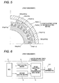
- Fig. 5 shows the electric motor.
- Fig. 6 shows a control system of the speed reduction and transmission mechanism.
- the first electric motor 3 has a stator 3a and a rotor 3b and is connected to the rear differential 107 via the speed reduction and transmission mechanism 2 on the rotational axis O (shown in Fig. 2 ), and the stator 3a is connected to the ECU 5. Additionally, the first electric motor 3 is configured so that when a control signal is inputted thereinto from the ECU 5, the stator 3a produces the first motor driving force a for operating the rear differential 107 between the rotor 3b and itself so as to rotate the rotor 3b.
- the stator 3a has a stator core 30a and coils 31a, is disposed on an inner circumferential side of the first electric motor 3 and is fixed to the differential carrier 106 (shown in Fig. 2 ).
- the stator core 30a includes, for example, a plurality of silicon steel plates which are laminated one on the top of the other and is made up of a cylindrical member as a whole.
- a plurality of (20 in this embodiment) tees 300a are provided side by side in a circumferential direction at equal intervals on an outer circumferential surface of the stator core 30a.
- the coil 31a is made up of an electric wire which is supplied with electric power from an onboard battery (not shown) and is wound around the tee 300a of the stator core 30a.
- the rotor 3b has a rotor core 30b and segment magnets 31b and is disposed on an outer circumferential side of the first electric motor 3.
- the rotor core 30b includes, for example, a plurality of silicon steel plates which are laminated one on the top of the other and is made up of a cylindrical member as a whole.
- the segment magnets 31b include a plurality of (four in this embodiment) permanent magnets which are magnetized to an N pole and an S pole from a rotor radial inner side towards a rotor radial outer side and a plurality of (four in this embodiment) permanent magnets which are magnetized to an N pole and an S pole from a rotor radial outer side towards a rotor radial inner side.
- These permanent magnets of the two types are aligned alternately side by side in the circumferential direction and are bonded to an inner circumferential surface of the rotor core 30b at equal intervals.
- the second electric motor 4 has a stator 4a and a rotor 4b and is connected to the rear differential 107 via the speed reduction and transmission mechanism 2 on the rotational axis O (shown in Fig. 2 ), and the stator 4a is connected to the ECU 5. Additionally, the second electric motor 4 is configured so that when a control signal is inputted thereinto from the ECU 5, the stator 4a produces the second motor driving force b for operating the rear differential 107 between the rotor 4b and itself so as to rotate the rotor 4b.
- the stator 4a has a stator core 40a and coils 41a, is disposed on an inner circumferential side of the second electric motor 4 and is fixed to the differential carrier 106.
- the stator 4a is connected to the stator 3a of the first electric motor 3 via a plurality of connecting pins 11.
- the stator 4a is mounted together with the stator 3a on the differential carrier 106 (shown in Fig. 2 ) with nuts 13 (shown in Fig. 2 ).
- the stator core 40a includes, for example, a plurality of silicon steel plates which are laminated one on the top of the other and is made up of a cylindrical member as a whole.
- a plurality of (20 in this embodiment) tees 400a are provided side by side in a circumferential direction at equal intervals on an outer circumferential surface of the stator core 40a.
- the coil 41a is made up of an electric wire which is supplied with electric power from the onboard battery (not shown) and is wound around the tee 400a of the stator core 40a.
- the rotor 4b has a rotor core 40b and segment magnets 41b, is disposed on an outer circumferential side of the second electric motor 4, and is connected to the rotor 3b of the first electric motor 3 via a connecting cylinder 10.
- the rotor core 40b includes, for example, a plurality of silicon steel plates which are laminated one on the top of the other and is made up of a cylindrical member as a whole.
- the segment magnets 41b include a plurality of (four in this embodiment) permanent magnets which are magnetized to an N pole and an S pole from a rotor radial inner side towards a rotor radial outer side and a plurality of (four in this embodiment) permanent magnets which are magnetized to an N pole and an S pole from a rotor radial outer side towards a rotor radial inner side.
- These permanent magnets of the two types are aligned alternately side by side in the circumferential direction and are bonded to an inner circumferential surface of the rotor core 40b at equal intervals.
- the ECU 5 is connected to a sensor (not shown) in addition to the first electric motor 3 and the second electric motor 4. Additionally, when a detection signal is inputted thereinto which signals that a driving torque which is smaller than a predetermined torque is required for the rear differential 107, the ECU 5 outputs a control signal to drive alternately the first electric motor 3 and the second electric motor 4, while the detection signal signals that a driving torque which is equal to or larger than the predetermined torque is required for the rear differential 107, the ECU 5 outputs a control signal to drive both the first electric motor 3 and the second electric motor 4.
- the ECU 5 puts the four-wheel-drive vehicle 101 in a four-wheel-drive state based on the front drive line system and the rear drive line system by not only operating the rear drive line system by driving at least one electric motor of the first electric motor 3 and the second electric motor 4 but also driving the front wheels 104 by the engine 102.
- the ECU 5 puts the four-wheel-drive vehicle 101 in a two-wheel-drive state by stopping the operation of the rear drive line system by stopping the driving of the first electric motor 3 and the second electric motor 4 while allowing the engine 102 to drive the front wheels 104.
- the eccentric cams 6, 7 rotate, for example, in the direction indicated by the arrow m1, and the transmission members 8, 9 perform circular motions in the direction indicated by the arrow n1 while sliding on each other with the transmission members 8, 9 each deviating the deviation amount ⁇ from the rotation axis O.
- the first motor driving force a is transmitted from the transmission members 8, 9 to the external gear 110c of the rear differential 107 (shown in Fig. 1 ), whereby the external gear 110c rotates in the opposite direction (the direction indicated by the arrow m2) to the rotating direction of the eccentric cams 6, 7.
- the motor driving force transmission device 1 to continue to operate when the driving torque which is smaller than the predetermined torque is required for the rear differential 107, when a predetermined period of time during which the first electric motor 3 is to be driven continuously elapses, the supply of electric power to the first driving motor 3 is stopped, and the second electric motor 4, which is the other electric motor, is driven.
- the first electric motor 3 is heated excessively in case the supply of electric power to the first electric motor 3 still continues even after the predetermined period of time elapses.
- the first electric motor 3 is prevented from being heated excessively by stopping the supply of electric power to the first electric motor 3.
- the second motor driving force b (shown in Fig. 6a ) of the second electric motor 4 is imparted to the speed reduction and transmission mechanism 2 via the connecting cylinder 10, whereby the speed reduction and transmission mechanism 2 is actuated. Because of this, in a similar way to the way in which the first electric motor 3 is driven, the second motor driving force b is transmitted to the rear differential 107 via the speed reduction and transmission mechanism 2. This actuates the rear differential 107, and the second motor driving force b is delivered to the rear axle shafts 108 to thereby be transmitted to the left and right rear wheels 105.
- the motor driving force transmission device 1 to continue to operate when the driving torque which is smaller than the predetermined torque is required for the rear differential 107, when a predetermined period of time during which the second electric motor 4 is to be driven continuously elapses, the supply of electric power to the second driving motor 4 is stopped, and the first electric motor 3 is driven.
- the first electric motor 3 and the second electric motor 4 are driven alternately to thereby restrain the first electric motor 3 and the second electric motor 4 from being heated excessively, thereby making it possible to allow the motor driving force transmission device 1 to operate continuously.
- the first electric motor 3 and the second electric motor 4 are disposed on the outer circumference of the rear differential 107, it is possible to reduce the axial and radial dimensions of the motor driving force transmission device 1.
- segment magnets 31b of the rotor 3b are bonded to the inner circumferential surface of the rotor core 30b and the segment magnets 41b of the rotor 4b are bonded to the inner circumferential surface of the rotor core 40b, there is no such situation that a force is applied to the segment magnets 31, 41b that is produced as a result of a centrifugal force being produced by the rotation of the rotors 3b, 4b and which attempts to separate the segment magnets 31b, 41b from the corresponding rotor cores 30b, 40b.
- the motor driving force transmission device 1 can also be actuated in a similar way to the way described in this embodiment even by rotating the eccentric cams 6, 7 in the direction indicated by the arrow m2. As this occurs, the external gear 110c rotates in the opposite direction (the direction indicated by the arrow m1) to the rotating direction of the eccentric cams 6, 7.
- first motor driving force a or the second motor driving force b is described as being transmitted from the speed reduction and transmission mechanism 2 to the rear differential 107, the invention is not limited thereto.
- torque which is equal to or larger than the predetermined torque is required for the rear differential 107, it is possible to transmit a motor driving force which is larger than the first motor driving force a and the second motor driving force b from the speed reduction and transmission mechanism 2 to the rear differential 107 by driving both the first electric motor 3 and the second electric motor 4.
- the speed reduction and transmission mechanism 2, the first electric motor 3 and the second electric motor 4 are disposed on the outer circumference of the rear differential 107, whereby the axial and radial dimensions of the motor driving force transmission device 1 (the device main body) can be reduced, thereby making it possible to realize a reduction in size of the device as a whole.
- the motor driving force transmission device 1 can be used continuously by employing alternately the first electric motor 3 and the second electric motor 4, whereby the first electric motor 3 and the second electric motor 4 are restrained from generating heat excessively even when the motor driving force transmission device 1 is operated continuously over a long period of time.
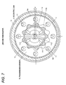
- Figs. 7 and 8 show a speed reduction and transmission mechanism.
- like reference numerals will be given to members which have the same or similar functions to those shown in Figs. 3 and 4 , and the detailed description thereof will be omitted here.
- a speed reduction and transmission mechanism 71 of a motor driving force transmission device is characterized in that a pair of transmission members 72, 73 are formed of internal gears having a cycloid tooth profile.
- an external gear 110c of a differential case 110 of a rear differential 107 is formed of an external gear having a cycloid tooth profile that has a smaller number of teeth than those of the pair of transmission members 72, 73 and which is normally in mesh with the pair of transmission members 72, 73.
- the pair of transmission members 72, 73 are disposed along a rotational axis O (shown in Fig. 2 ) and are connected to the external gear 110c at portions which are spaced 180° apart from each other around the rotational axis (the rotational axis O) thereof.
- the speed reduction and transmission mechanism 2 Similar to the motor driving force transmission device 1 described in the first embodiment, the speed reduction and transmission mechanism 2, a first electric motor 3 and a second electric motor 4 are disposed on an outer circumference of the rear differential 107, and therefore, it is possible to reduce an axial and radial dimensions of the motor driving force transmission device 1.
- Fig. 9 shows a motor driving force transmission device.
- like reference numerals will be given to members which have the same or like functions to those shown in Fig. 2 , and the detailed description thereof will be omitted here.
- a motor driving force transmission device 80 is characterized by including a housing 81 of which a rotational axis O is an axis of rear axle shafts 108, a rear differential 107 which delivers a motor driving force to rear wheels 105, an electric motor 82 which generates a motor driving force for operating the rear differential 107 and a speed reduction and transmission mechanism 2 which reduces the speed of the driving force of the electric motor 82 to transmit it to the rear differential 107, with the speed reduction and transmission mechanism 2 disposed on the same axis as an axis of the electric motor 82 (the rotational axis O).
- the electric motor 82 is substantially the same in configuration as the first electric motor 3 and the second electric motor 4 which are described in the first embodiment, corresponding reference numerals will be given to portions corresponding to the portions of, for example, the first electric motor 3 (reference numerals 82a and 82b will be given to a stator of the electric motor 82 and a rotor of the electric motor 82, respectively, so as to correspond to the stator 3a and the rotor 3b of the first electric motor 3).
- one side end portion and the other side end portion of a differential case 110 is supported rotatably on a bearing mounting portion 810b of a first housing element 810 via a ball bearing 86 and on a bearing mounting portion 830b of a stator supporting member 83 via a ball bearing 87, respectively.
- the housing 81 has the first housing element 810 which accommodates the rear differential 107 and the speed reduction and transmission mechanism 2 and a second housing element 811 that communicates with the first housing element 810 and accommodates the electric motor 82 (except some parts) and which is disposed on a vehicle body.
- the first housing element 810 is disposed at one side of the housing 81 and is formed of a stepped and bottomed cylindrical member which is opened in a side which faces the second housing element 811 as a whole.
- a shaft insertion hole 810a is provided in a bottom portion of the first housing element 810, allowing the rear axle shaft 108 to be inserted therethrough.
- a cover 115 which covers an opening portion in the shaft insertion hole 810a is interposed between one of the rear wheels 105 and the shaft insertion hole 810a.
- the cover 115 has a cylindrical portion 115a through which the rear axle shaft 108 is inserted, and an inner circumferential surface of the cylindrical portion 115a is attached to an outer circumferential surface of the rear axle shaft 108.
- a seal member 116 which seals up the opening portion in the shaft insertion hole 810a is attached to an inner circumferential surface of the shaft insertion hole 810a.
- a differential case bearing mounting portion 810b is provided on the inner circumferential surface of the shaft insertion hole 810a.
- An attaching flange 810c is provided integrally at an opening end portion of the first housing element 810 so as to project from an outer circumferential surface thereof.
- a plurality of (six in this embodiment) pin mounting holes 810d are arranged at equal intervals around the rotational axis O in the first housing element 810 so that connecting pins 11 are mounted therein.
- the second housing element 811 is disposed at the other side of the housing 81 and is formed of a bottomed cylindrical member which is opened in a side which faces the first housing element 810 as a whole.
- a shaft insertion hole 811a through which the rear axle shaft 108 is inserted is provided in a bottom portion of the second housing element 811.
- a cover 117 which covers an opening portion in the shaft insertion hole 811a is interposed between the other of the rear wheels 105 and the shaft insertion hole 811a.
- the cover 117 has a cylindrical portion 117a through which the rear axle shaft 108 is inserted, and an inner circumferential surface of the cylindrical portion 117a is attached to an outer circumferential surface of the rear axle shaft 108.
- a seal member 118 which seals up the opening portion in the shaft insertion hole 811a is attached to an inner circumferential surface of the shaft insertion hole 811a.
- a first rising portion 811b and a second rising portion 811c are provided integrally on a bottom portion of the second housing element 811 so that the first rising portion 811b projects therefrom at an inner opening circumferential edge of the shaft insertion hole 811a and that the second rising portion 811c projects therefrom in a position lying radially outwards of the first rising portion 811b.
- the cylindrical stator supporting portion 83 which faces oppositely the bottom portion of the second housing element 811 across the electric motor 82, is attached together with the stator 82a of the electric motor 82 to the first rising portion 811b with attaching bolts 84.
- the stator supporting member 83 has a shaft insertion hole 83a through which the rear axle shaft 108 is inserted and is interposed between the electric motor 82 and the speed reduction and transmission mechanism 2.
- a flange 83b is provided integrally on an outer circumferential surface of the stator supporting member 83 so as to project therefrom.
- a differential case bearing mounting portion 830b is provided on an inner circumferential surface of the flange 83b.
- a plurality of (six in this embodiment) pin mounting holes 831b are provided in the flange 83b so that connecting pins 11 are mounted therein.
- a shaft bearing mounting portion 811b and a rotor bearing mounting portion 8110c are provided on an inner circumferential surface of the first rising portion 811b and on an outer circumferential surface of the second rising portion 811c, respectively.
- the electric motor 82 is made up of an outer rotor motor which includes the stator 82a and the rotor 82b and is connected to the rear differential 107 via the speed reduction and transmission mechanism 2 on the motor axis (the rotational axis O), and the stator 82a is connected to an ECU 5 (shown in Figs. 2 and 5 ). Then, in the electric motor 82, when a control signal is inputted into the stator 82a from the ECU 5, a motor driving force which operates the rear differential 107 is generated between the stator 82a and the rotor 82b so as to rotate the rotor 82b.
- the stator 82a is disposed on an inner circumferential side of the electric motor 82 and is attached together with the stator supporting member 83 to the first rising portion 811b of the second housing element 811 with the attaching bolts 84.
- the rotor 82b is disposed on an outer circumferential side of the electric motor 82 and is supported rotatably on a rotor bearing mounting portion 8110c on the second rising portion 811c via a bearing 85.
- the speed reduction and transmission mechanism 2 has a pair of eccentric cams 6, 7 which are driven to rotate by the electric motor 82 and a pair of transmission members 8, 9 which oscillate in association with the rotation of the pair of eccentric cams 6, 7 and is disposed on an outer circumference of the rear differential 107 on the same axis as an axis of the electric motor 82 (the rotational axis O).
- the transmission member 8 oscillates so that an axis O1 thereof moves in the direction indicated by the arrow n1 about the rotational axis O.
- the transmission member 8 oscillates so that the axis O1 thereof moves in the direction indicated by the arrow n2 (the opposite direction to the direction indicated by the arrow n1) about the rotational axis O.
- the transmission member 8 moves the axis O1 along a circumferential direction of a circle that is centered at the rotational axis O and which has a radius equal to a deviation amount ⁇ and revolves without rotating one full rotation relative to the housing (a device main body) 81.
- the transmission member 9 oscillates so that an axis 02 thereof moves in the direction indicated by the arrow n1 about the rotational axis O.
- the transmission member 9 oscillates so that the axis 02 thereof moves in the direction indicated by the arrow n2 (the opposite direction to the direction indicated by the arrow n1) about the rotational axis O.
- the transmission member 9 moves the axis 02 along a circumferential direction of a circle that is centered at the rotational axis O and which has a radius equal to a deviation amount ⁇ and revolves without rotating one full rotation relative to the housing (the device main body) 81.
- the motor driving force transmission device 80 which is configured in this way, when the electric motor 82 is driven by supplying electric power to the electric motor 82, the motor driving force of the electric motor 82 is imparted to the speed reduction and transmission mechanism 2 via a connecting cylinder 10, whereby the speed reduction and transmission mechanism 2 operates in a similar way to the way in which the motor driving force transmission device 1 described in the first embodiment operates.
- the radial dimension of the motor driving force transmission device 1 (the device main body) can be reduced by disposing the speed reduction and transmission mechanism 2 on the outer circumference of the electric motor 8, thereby making it possible to realize a reduction in size of the device in the radial direction thereof.
- Fig. 10 shows a motor driving force transmission device.
- like reference numerals will be given to members having functions like or similar to those of the members shown in Fig. 9 , and the detailed description thereof will be omitted here.
- a motor driving force transmission device 90 is characterized in that eccentric cams 6, 7 are disposed on outer circumferences of portions 110g, 110h which lie on an outer circumferential portion of a differential case (an input member) 110 of a rear differential 107 and have outside diameters which are smaller than a largest outside diameter D1 of the differential case 110.
- the differential case 110 is formed of a rotational member which includes the portions 110g, 110h and has a portion 110d which supports a pinion gear shaft 111 at an axially central portion thereof, the rotational member additionally having portions 110e, 110f where ball bearings 86, 87 are mounted at axial end portions thereof and being formed symmetrical relative to a rotational axis O and an axis L.
- An outside diameter D1 of the portion 110d is set to a largest dimension in outside diameters of outer circumferential portions on the differential case 110.
- the portion 110e is disposed on one axial side of the portion 110d, and the portion 110f is disposed on the other axial side of the portion 110d.
- An outside diameter D2 of the portion 110e is set to a dimension which is smaller than an outside diameter D3 of the portion 110f (D3 > D2).
- the outside diameter D2 of the portion 110e and the outside diameter D3 of the portion 110f are both set to the dimensions which are smaller than the outside diameter D1 of the portion 110d (D1 > D3 > D2).
- the portions 110g, 110h are disposed in line in the axial direction (the rotational axis O) of the differential case 110. Additionally, the portion 110g is interposed between the portion 110d and the portion 110e, and the portion 110h is interposed between the portion 110d and the portion 110f.
- Outside diameters of the portions 110g, 110h are substantially equal (referred to as D4) and are set to a dimension which is larger than the outside diameters D2, D3 (D3 ⁇ D4) but is smaller than the outside diameter D1 (D1 > D3).
- An external gear 110i which meshes with one transmission member 8 of transmission members is mounted on an outer circumferential portion of the portion 110g, and an external gear 110j which meshes with the other transmission member 9 is mounted on an outer circumferential portion of the portion 110h.
- a gear that employs the rotational axis O as a gear axis thereof and which has an involute tooth profile is used for the external gears 110i, 110j.
- Connecting pins 11 are inserted through pin insertion holes 8a in the one transmission member 8, and the transmission member 8 is supported rotatably (so as to perform a circular motion) by the connecting pins 11 via a needle roller bearing 88.
- the eccentric cam (a first eccentric cam) 6 is disposed rotatably on an outer circumferential portion of the one transmission member 8 via a needle roller bearing 12.
- the one transmission member 8 is restricted from moving in an axial direction towards the other transmission member 9 by a movement restricting member 98.
- the connecting pins 11 are inserted through pin insertion holes 9a in the other transmission member 9, and the transmission member 9 is supported rotatably (so as to perform a circular motion) by the connecting pins 11 via a needle roller bearing 88.
- the eccentric cam (a second eccentric cam) 7 is disposed rotatably on an outer circumferential portion of the other transmission member 9 via a needle roller bearing 12.
- the other transmission member 9 is restricted from moving in an axial direction towards the one transmission member 8 by a movement restricting member 99.
- the motor driving force transmission device 90 which is configured in this way, when an electric motor 82 is driven by supplying electric power to the electric motor 82, the motor driving force of the electric motor 82 is imparted to a speed reduction and transmission mechanism 2 via a connecting cylinder 10, whereby the speed reduction and transmission mechanism 2 operates in a similar way to the way in which the motor driving force transmission device 80 described in the third embodiment operates.
- the eccentric cams 6, 7 are disposed on the outer circumferential portion of the differential case 110 at the outer circumferences of the portions 110g, 110h whose outside diameters D4 are smaller than the largest outside diameter D1 of the differential case 110, whereby the radial dimension of the motor driving force transmission device 90 can be reduced, thereby making it possible to realize a reduction in size of the device in the radial direction.
- the reduction in size of the device in the radial direction is enabled by disposing the speed reduction and transmission mechanism 2 by making use of space portions (so-called dead spaces) which are situated on both axial sides of the portion 110d of the differential case 110, and therefore, this size reduction is attained by avoiding the enlargement of the motor driving force transmission device 90 in the axial direction.
- the ball bearings 86, 87 can be disposed at the portions 110e, 110f whose outside diameters D2, D3 are smaller than the outside diameters D4 of the portions 110g, 110h, and therefore, the ball bearings 86, 87 can be made small in size, thereby making it possible to realize a reduction in production costs.
- a rotor 82b is disposed on an outer circumference of a stator 82a of the electric motor 82, and therefore, similar to the advantage described in the third embodiment, a larger motor driving force can be produced than when the rotor is disposed on the inner circumference of the stator.
- the invention is not limited thereto.
- the electric motors may be switched to be driven alternately when the integral value of the motor current of the first electric motor or the second electric motor reaches or exceeds a predetermined threshold. Additionally, the electric motors may be switched to be driven alternately when the temperature of the first electric motor or the second electric motor reaches or exceeds a predetermined threshold or when the rotational speed of the first electric motor or the second electric motor reaches a predetermined threshold.
- the one eccentric cam 6 and the other eccentric cam 7 are described as being installed on the inner circumferential surface of the second connecting member (the connecting cylinder) 10 so that the distance from the center point O1 of the through hole 6a to the rotation axis O equals the distance from the center point 02 of the through hole 7a to the rotational axis O and that the point O1 and the point 02 are spaced equidistantly apart from each other around the rotational axis O, and the pair of transmission members 8, 9 (the transmission members 72, 73) are described as being provided on the rear differential 107 at the portions which are spaced equidistantly (180°) apart from each other around the rotational axis.
- the invention is not limited thereto, and the number of transmission members can be changed as required. Namely, when the number of transmission members is n (n ⁇ 3), assuming that a center point of a through hole of a first eccentric cam, a center point of a through hole of a second eccentric cam, ...
- the eccentric cams are installed on the inner circumferential surface of the second connecting member so that distances from the center points of the through holes to the rotational axis equal each other and that an included angle which is formed by lines which connect the center points of the through holes of any two adjacent eccentric cams of the first eccentric cam, the second eccentric cam, ...
- the n transmission members are provided on the rear differential at portions which are spaced apart from each other at angular intervals of 360°/n around the rotational axis thereof.
- the three transmission members are installed on the inner circumferential surface of the second connecting member so that distances from the center points of the through holes to the rotational axis of the second connecting member equal each other and that an included angle which is formed by lines which connect the center points of the through holes of any two adjacent eccentric cams of the first eccentric cam, the second eccentric cam and the third eccentric cam and the rotational axis of the second connecting member is 120°, and the three transmission members are provided on the rear differential at portions which are spaced apart from each other at angular intervals of 120° around the rotational axis thereof.
- the radial dimension of the device main body can be reduced, thereby making it possible to realize a reduction in size of the device in the radial direction.
Landscapes
- Engineering & Computer Science (AREA)
- Mechanical Engineering (AREA)
- Transportation (AREA)
- Combustion & Propulsion (AREA)
- Chemical & Material Sciences (AREA)
- Power Engineering (AREA)
- General Engineering & Computer Science (AREA)
- Automation & Control Theory (AREA)
- Life Sciences & Earth Sciences (AREA)
- Sustainable Energy (AREA)
- Sustainable Development (AREA)
- Electromagnetism (AREA)
- Physics & Mathematics (AREA)
- Arrangement Or Mounting Of Propulsion Units For Vehicles (AREA)
- Connection Of Motors, Electrical Generators, Mechanical Devices, And The Like (AREA)
- Retarders (AREA)
- Electric Propulsion And Braking For Vehicles (AREA)
- Hybrid Electric Vehicles (AREA)
- Power Steering Mechanism (AREA)
- Braking Arrangements (AREA)
Abstract
[Problem] To provide a device for transmitting the driving force of motors, the device being configured so that the dimension of the device body in the radial direction is reduced to make the device compact in the radial direction. [Solution] A device (1) for transmitting the driving force of motors comprises: the electric motors (3, 4) for generating driving force for operating a rear differential (107); and a speed reducing and transmitting mechanism (2) for reducing the speed of the driving force of the electric motors (3, 4) and transmitting the driving force to the rear differential (107). The speed reducing and transmitting mechanism (2) has: eccentric cams (6, 7) rotated by the drive of the electric motors (3, 4); and transmitting members (8, 9) rotated by the rotation of the eccentric cams (6, 7). The speed reducing and transmitting mechanism (2) is disposed around the outer periphery of the rear differential (107).
Description
- The present invention relates to a motor driving force transmission device which is preferably used in an electric vehicle having, for example, an electric motor as a drive source.
- In conventional motor driving force transmission devices, there are driving force transmission devices that include an electric motor which produces a motor driving force and a speed reduction and transmission mechanism for transmitting the motor driving force of the electric motor to a differential mechanism, which are installed in a motor vehicle (refer to
Patent Literature 1, for example). - The electric motor has an output shaft that rotates based on electric power of an onboard battery and which is disposed on an axis of the speed reduction and transmission mechanism.
- The speed reduction and transmission mechanism has a pair of speed reduction and transmission portions on the periphery of its axis and is disposed sideways of the differential mechanism, being connected to the electric motor and the differential mechanism (a differential case). One of the speed reduction and transmission portions is connected to the output shaft of the electric motor, and the other is connected to the differential case side.
- In this configuration, the output shaft of the electric motor rotates based on the electric power of the onboard battery, and in association with the rotation of the electric motor, the motor driving force is transmitted from the electric motor to the differential mechanism via the speed reduction and transmission mechanism. Then, the motor driving force transmitted to the differential mechanism is delivered to left and right wheels from the differential mechanism.
- Patent Literature 1:
JP-A-2007-218407 - According to the motor driving force transmission device described in
Patent Literature 1, however, the speed reduction and transmission mechanism is disposed on the axis which is parallel to the axis of the differential mechanism. As a result of this, a radial dimension of the whole device is increased, leading to a problem that the whole device is increased in size. - Consequently, an object of the invention is to provide a motor driving force transmission device which can reduce the radial dimension of the whole of the device to thereby realize a reduction in size in the radial direction of the device. Means for Solving the Problem
- With a view to attaining the object, the invention provides a motor driving force transmission device which will be described under (1) to (9).
- (1) There is provided a motor driving force transmission device comprising an electric motor which generates a motor driving force for operating a differential mechanism and a speed reduction and transmission mechanism which is configured to reduce speed of the motor driving force of the electric motor to transmit to the differential mechanism, wherein the speed reduction and transmission mechanism includes an eccentric cam which is configured to rotate as the electric motor is driven and a transmission member which is configured to rotate as the eccentric cam rotates, and the speed reduction and transmission mechanism is disposed on an outer circumference of the differential mechanism.
- (2) In the motor driving force transmission device according to (1) above, the electric motor is disposed on the outer circumference of the differential mechanism.
- (3) In the motor driving force transmission device according to (1) or (2) above, the electric motor includes a stator which is fixed to a device main body and a rotor which is configured to rotate around an outer circumference of the stator.
- (4) In the motor driving force transmission device according to any of (1) to (3) above, the electric motor includes a first electric motor which is configured to produce a first motor driving force and a second electric motor which is connected to the first electric motor and is configured to produce a second motor driving force, the first electric motor and the second electric motor being connected to the differential mechanism via the speed reduction and transmission mechanism.
- (5) In the motor driving force transmission device according to (4) above, in the speed reduction and transmission mechanism, the eccentric cam includes a plurality of eccentric cams which are configured to rotate as at least one of the first electric motor and the second electric motor is driven, and the transmission member includes a plurality of transmission members which are configured to rotate as the plurality of eccentric cams rotate.
- (6) In the motor driving force transmission device according to (5) above, in the speed reduction and transmission mechanism, the plurality of transmission members are provided on the differential mechanism at portions which are spaced apart from each other at equal intervals around a rotational axis of the differential mechanism.
- (7) In the motor driving force transmission device according to any of (1) to (6) above, in the speed reduction and transmission mechanism, the plurality of transmission member includes internal gears which are configured to mesh with an input member of the differential mechanism via external gears.
- (8) In the motor driving force transmission device according to any of (1) to (7) above, in the speed reduction and transmission mechanism, the plurality of eccentric cams are disposed around an outer circumference of a portion of an outer circumferential portion of the input member of the differential mechanism, the portion having an outside diameter smaller than a largest outside diameter of the differential mechanism.
- (9) In the motor driving force transmission device according to (8) above, in the speed reduction and transmission mechanism, the plurality of eccentric cams are a first eccentric cam which is positioned on one axial side of an axial central portion of the input member and a second eccentric cam which is positioned on the other axial side of the axial central portion of the input member, the first eccentric cam and the second eccentric cam being disposed in line in an axial direction of the input member.
- According to the invention, it is possible to reduce a radial dimension of the device main body, and hence, it is possible to realize a reduction in size of the device in a radial direction.
-
-
Fig. 1 is a plan view shown to schematically illustrate a vehicle in which a motor driving force transmission device according to a first embodiment of the invention is installed. -
Fig. 2 is a sectional view shown to illustrate the motor driving force transmission device according to the first embodiment of the invention. -
Fig. 3 is a sectional view (a sectional view taken along the line A-A inFig. 2 ) showing a speed reduction and transmission mechanism of the motor driving force transmission device according to the first embodiment of the invention. -
Fig. 4 is a sectional view showing an operating state of the speed reduction and transmission mechanism of the motor driving force transmission device according to the first embodiment of the invention. -
Fig. 5 is a sectional view shown to illustrate an electric motor of the motor driving force transmission device according to the first embodiment of the invention. -
Fig. 6 is a block diagram shown to illustrate the motor driving force transmission device according to the first embodiment of the invention. -
Fig. 7 is a sectional view showing a speed reduction and transmission mechanism of a motor driving force transmission device according to a second embodiment of the invention. -
Fig. 8 is a sectional view showing an operating state of the speed reduction and transmission mechanism of the motor driving force transmission device according to the second embodiment. -
Fig. 9 is a sectional view shown to illustrate a motor driving force transmission device according to a third embodiment of the invention. -
Fig. 10 is a sectional view shown to illustrate a motor driving force transmission device according to a fourth embodiment of the invention. - Hereinafter, a motor driving force transmission device according to a first embodiment of the invention will be described in detail by reference to the drawings.
-
Fig. 1 shows schematically a four-wheel-drive vehicle. As shown inFig. 1 , a four-wheel-drive vehicle 101 employs a front drive line system related with front wheels which employs an engine as a drive source and a rear drive line system related with rear wheels which employs an electric motor as a drive source and includes a motor drivingforce transmission device 1, anengine 102, atransaxle 103, a pair offront wheels 104, and a pair ofrear wheels 105. - The motor driving
force transmission device 1 is disposed in the rear drive line system of the four-wheel-drive vehicle 101 and is supported together with arear differential 107 on a vehicle body (not shown) of the four-wheel-drive vehicle 101 via a differential carrier (a device main body) 106. - Additionally, the motor driving
force transmission device 1 is designed to transmit a motor driving force of an electric motor (which will be described later) to the pair ofrear wheels 105. This configuration enables the motor driving force of the electric motor to be outputted torear axle shafts 108 via the motor drivingforce transmission device 1 and therear differential 107, whereby the pair ofrear wheels 105 are driven. The motor drivingforce transmission device 1 will be described in detail later. - The
engine 102 is disposed in the front drive line system of the four-wheel-drive vehicle 101. This configuration allows a driving force of theengine 102 to be outputted tofront axle shafts 109 via thetransaxle 103, whereby the pair offront wheels 104 are driven. -
Fig. 2 shows the whole of the motor driving force transmission device. As shown inFig. 2 , the motor drivingforce transmission device 1 substantially includes a speed reduction andtransmission mechanism 2 which reduces the speed of at least one motor driving force of a first motor driving force a and a second motor driving force b (both of which are shown inFig. 6 ) and transmits it to therear differential 107, a firstelectric motor 3 which produces the first motor driving force a, a secondelectric motor 4 which produces the second motor driving force b, and a vehicle ECU (Electronic Control Unit) 5 which functions as a control unit for outputting control signals which control the firstelectric motor 3 and the secondelectric motor 4. - The
rear differential 107 is made up of a differential mechanism of a bevel gear type having a differential case (an input member) 110, apinion gear shaft 111, a pair ofpinion gears 112 and a pair ofside gears 113 and is accommodated within thedifferential carrier 106. - By adopting this configuration, a rotational force of the
differential case 110 is delivered from thepinion gear shaft 111 to theside gears 113 via thepinion gears 112 and is further transmitted to the left and rightrear wheels 105 from therear axle shafts 108. - On the other hand, when a driving resistance is produced between the left and right
rear wheels 105, the rotational force of thedifferential case 110 is delivered to the left and rightrear wheels 105 in a differential fashion as a result of spinning or rotating of thepinion gears 112. - The
differential case 110 has anaccommodating space 110a andshaft insertion holes 110b in an interior thereof and is disposed rotatably within thedifferential carrier 106 viatapered roller bearings 114. Additionally, thedifferential case 110 is designed to rotate around a rotational axis O when receiving at least one motor driving force of the first motor driving force a and the second motor driving force b. Anexternal gear 110c is mounted on thedifferential case 110, which has an involute tooth profile and employs the rotational axis O as a gear axis thereof. - The
pinion gear shaft 111 is disposed on an axis L which intersects the rotational axis O at right angles within theaccommodating space 110a in thedifferential case 110 and is restricted from rotating around the axis L. - The pair of
pinion gears 112 are supported rotatably on thepinion gear shaft 111 and are accommodated in theaccommodating space 110a in thedifferential case 110. - The pair of
side gears 113 are accommodated within theaccommodating space 110a in thedifferential case 110 and are connected to therear axle shafts 108 which pass through theshaft insertion holes 110b through spline fitting. Additionally, the pair ofside gears 113 are disposed so that their gear axes intersect gear axes of the pair ofpinion gears 112 at right angles so as to mesh with the pair ofpinion gears 112. -
Figs. 3 and4 show the speed reduction and transmission mechanism. As shown inFigs. 3 and4 , the speed reduction andtransmission mechanism 2 has a pair ofeccentric cams electric motor 3 and the second electric motor 4 (both of which are shown inFig. 2 ) is driven and a pair oftransmission members eccentric cams rear differential 107 while being interposed between the firstelectric motor 3 and the secondelectric motor 4 on the rotational axis O (shown inFig. 2 ). - The pair of
eccentric cams - The
eccentric cam 6, which is one of the pair of eccentric cams, has a throughhole 6a which is centered at a point (an axis) O1 which deviates a deviation amount δ1 (δ1=δ) from a center (a point on the rotational axis O) thereof, and is disposed to face the firstelectric motor 3. Theeccentric cam 6 is designed to cause thetransmission member 8 to perform a circular motion which deviates a deviation amount δ from the rotational center O when receiving at least one motor driving force of the first motor driving force a and the second motor driving force b. When theeccentric cam 6 rotates in one circumferential direction (a direction indicated by an arrow m1), thetransmission member 8 oscillates so that the axis O1 thereof moves in a direction indicated by an arrow n1 about the rotational axis O. When theeccentric cam 6 rotates in the other circumferential direction (a direction indicated by an arrow m2), thetransmission member 8 oscillates so that the axis O1 thereof moves in a direction indicated by an arrow n2 (an opposite direction to the direction indicated by the arrow n1) about the rotational axis O. Thetransmission member 8 moves the axis O1 along a circumferential direction of a circle that is centered at the rotational axis O and which has a radius equal to the deviation amount δ and revolves without rotating one full rotation relative to the differential carrier (the device main body) 106. - The other
eccentric cam 7 has a throughhole 7a which is centered at a point (an axis) 02 which deviates a deviation amount δ2 (δ2=δ) from a center (a point on the rotational axis O) thereof, and is disposed to face the secondelectric motor 4. The othereccentric cam 7 is designed to cause thetransmission member 9 to perform a circular motion which deviates the deviation amount δ from the rotational center O when receiving at least one motor driving force of the first motor driving force a and the second motor driving force b. When theeccentric cam 7 rotates in the one circumferential direction (the direction indicated by the arrow m1), thetransmission member 9 oscillates so that theaxis 02 thereof moves in the direction indicated by the arrow n1 about the rotational axis O. When theeccentric cam 7 rotates in the other circumferential direction (the direction indicated by the arrow m2), thetransmission member 9 oscillates so that theaxis 02 thereof moves in the direction indicated by the arrow n2 (the opposite direction to the direction indicated by the arrow n1) about the rotational axis O. Thetransmission member 9 moves theaxis 02 along a circumferential direction of a circle that is centered at the rotational axis O and which has a radius equal to the deviation amount δ and revolves without rotating one full rotation relative to the differential carrier (the device main body) 106. - The one
eccentric cam 6 and the othereccentric cam 7 are mounted on the inner circumferential surface of the second connecting member (the connecting tube) 10 so that a distance from the center point O1 of the throughhole 6a to the rotational axis O and a distance from thecenter point 02 of the throughhole 7a to the rotational axis O are equal and that circumferential distances of the pint O1 and thepoint 02 around the rotational axis O are equal. - The pair of
transmission members external gear 110c of thedifferential case 110, are disposed along the rotational axis O and are provided on theexternal gear 110c at portions which are spaced apart from each other at equal intervals (180°) around the rotational axis (the rotational axis O) of theexternal gear 110c. By adopting this configuration, the speed reduction andtransmission mechanism 2 is connected to the rear differential 107 in a well-balanced fashion. Internal gears having an involute tooth profile are employed for the pair oftransmission members external gear 110c and which are in mesh with theexternal gears 110c having the involute tooth profile at all times. A speed reduction ratio of the speed reduction andtransmission mechanism 2 is calculated by diving (Z2-Z1) by Z2 or (Z2-Z1)/Z2. - The
transmission member 8, which is one of the pair of transmission members, is disposed rotatably on an inner surface of the throughhole 6a in theeccentric cam 6, which is one of the pair of eccentric cams, via aneedle roller bearing 12. A plurality ofpin insertion holes 8a are disposed in thetransmission member 8 at equal intervals in a circumferential direction thereof so that a plurality of first connecting members (connecting pins) 11 are inserted therethrough, eachpin insertion hole 8a having a bore diameter which is larger than a dimension resulting from adding the deviation amount δ to a pin diameter of each connectingpin 11. - The
transmission member 9, which is the other of the pair of transmission members, is disposed rotatably on an inner surface of the throughhole 7a in theeccentric cam 7, which is the other of the pair of eccentric cams, via aneedle roller bearing 12. Similarly to thetransmission member 8, a plurality ofpin insertion holes 9a are disposed in theother transmission member 9 at equal intervals in a circumferential direction thereof so that the plurality of connectingpins 11 are inserted therethrough, eachpin insertion hole 9a having a bore diameter which is larger than the dimension resulting from adding the deviation amount δ to the pin diameter of each connectingpin 11. -
Fig. 5 shows the electric motor.Fig. 6 shows a control system of the speed reduction and transmission mechanism. As shown inFigs. 5 and 6 , the firstelectric motor 3 has astator 3a and arotor 3b and is connected to therear differential 107 via the speed reduction andtransmission mechanism 2 on the rotational axis O (shown inFig. 2 ), and thestator 3a is connected to theECU 5. Additionally, the firstelectric motor 3 is configured so that when a control signal is inputted thereinto from theECU 5, thestator 3a produces the first motor driving force a for operating the rear differential 107 between therotor 3b and itself so as to rotate therotor 3b. - The
stator 3a has astator core 30a andcoils 31a, is disposed on an inner circumferential side of the firstelectric motor 3 and is fixed to the differential carrier 106 (shown inFig. 2 ). - The
stator core 30a includes, for example, a plurality of silicon steel plates which are laminated one on the top of the other and is made up of a cylindrical member as a whole. A plurality of (20 in this embodiment)tees 300a are provided side by side in a circumferential direction at equal intervals on an outer circumferential surface of thestator core 30a. - The
coil 31a is made up of an electric wire which is supplied with electric power from an onboard battery (not shown) and is wound around thetee 300a of thestator core 30a. - The
rotor 3b has a rotor core 30b andsegment magnets 31b and is disposed on an outer circumferential side of the firstelectric motor 3. - The rotor core 30b includes, for example, a plurality of silicon steel plates which are laminated one on the top of the other and is made up of a cylindrical member as a whole.
- The
segment magnets 31b include a plurality of (four in this embodiment) permanent magnets which are magnetized to an N pole and an S pole from a rotor radial inner side towards a rotor radial outer side and a plurality of (four in this embodiment) permanent magnets which are magnetized to an N pole and an S pole from a rotor radial outer side towards a rotor radial inner side. These permanent magnets of the two types are aligned alternately side by side in the circumferential direction and are bonded to an inner circumferential surface of the rotor core 30b at equal intervals. - The second
electric motor 4 has astator 4a and arotor 4b and is connected to therear differential 107 via the speed reduction andtransmission mechanism 2 on the rotational axis O (shown inFig. 2 ), and thestator 4a is connected to theECU 5. Additionally, the secondelectric motor 4 is configured so that when a control signal is inputted thereinto from theECU 5, thestator 4a produces the second motor driving force b for operating the rear differential 107 between therotor 4b and itself so as to rotate therotor 4b. - The
stator 4a has astator core 40a andcoils 41a, is disposed on an inner circumferential side of the secondelectric motor 4 and is fixed to thedifferential carrier 106. In addition, thestator 4a is connected to thestator 3a of the firstelectric motor 3 via a plurality of connecting pins 11. Thestator 4a is mounted together with thestator 3a on the differential carrier 106 (shown inFig. 2 ) with nuts 13 (shown inFig. 2 ). - The
stator core 40a includes, for example, a plurality of silicon steel plates which are laminated one on the top of the other and is made up of a cylindrical member as a whole. A plurality of (20 in this embodiment)tees 400a are provided side by side in a circumferential direction at equal intervals on an outer circumferential surface of thestator core 40a. - The
coil 41a is made up of an electric wire which is supplied with electric power from the onboard battery (not shown) and is wound around thetee 400a of thestator core 40a. - The
rotor 4b has a rotor core 40b andsegment magnets 41b, is disposed on an outer circumferential side of the secondelectric motor 4, and is connected to therotor 3b of the firstelectric motor 3 via a connectingcylinder 10. - The rotor core 40b includes, for example, a plurality of silicon steel plates which are laminated one on the top of the other and is made up of a cylindrical member as a whole.
- The
segment magnets 41b include a plurality of (four in this embodiment) permanent magnets which are magnetized to an N pole and an S pole from a rotor radial inner side towards a rotor radial outer side and a plurality of (four in this embodiment) permanent magnets which are magnetized to an N pole and an S pole from a rotor radial outer side towards a rotor radial inner side. These permanent magnets of the two types are aligned alternately side by side in the circumferential direction and are bonded to an inner circumferential surface of the rotor core 40b at equal intervals. - The
ECU 5 is connected to a sensor (not shown) in addition to the firstelectric motor 3 and the secondelectric motor 4. Additionally, when a detection signal is inputted thereinto which signals that a driving torque which is smaller than a predetermined torque is required for therear differential 107, theECU 5 outputs a control signal to drive alternately the firstelectric motor 3 and the secondelectric motor 4, while the detection signal signals that a driving torque which is equal to or larger than the predetermined torque is required for therear differential 107, theECU 5 outputs a control signal to drive both the firstelectric motor 3 and the secondelectric motor 4. - By adopting this configuration, the
ECU 5 puts the four-wheel-drive vehicle 101 in a four-wheel-drive state based on the front drive line system and the rear drive line system by not only operating the rear drive line system by driving at least one electric motor of the firstelectric motor 3 and the secondelectric motor 4 but also driving thefront wheels 104 by theengine 102. - In addition, while the four-wheel-
drive vehicle 101 is running normally, theECU 5 puts the four-wheel-drive vehicle 101 in a two-wheel-drive state by stopping the operation of the rear drive line system by stopping the driving of the firstelectric motor 3 and the secondelectric motor 4 while allowing theengine 102 to drive thefront wheels 104. - Next, the operation of the motor driving
force transmission device 1 illustrated in this embodiment will be described by usingFigs. 1 to 4 and6 . - In
Fig. 2 , when, by supplying electric power to one electric motor of the firstelectric motor 3 and the second electric motor 4 (for example, the first electric motor 3) of the four-wheel-drive vehicle 101 (shown inFig. 1 ), the firstelectric motor 3 is driven, the first motor driving force a (shown inFig. 6 ) of this firstelectric motor 3 is imparted to the speed reduction andtransmission mechanism 2 via the connectingcylinder 10, whereby the speed reduction andtransmission mechanism 2 is actuated. - Because of this, in the speed reduction and
transmission mechanism 2, as shown inFigs. 3 and4 , theeccentric cams transmission members transmission members - In conjunction with this, the first motor driving force a is transmitted from the
transmission members external gear 110c of the rear differential 107 (shown inFig. 1 ), whereby theexternal gear 110c rotates in the opposite direction (the direction indicated by the arrow m2) to the rotating direction of theeccentric cams - This actuates the
rear differential 107, and the first motor driving force a is delivered to therear axle shafts 108 to thereby be transmitted to the left and rightrear wheels 105. - Here, to allow the motor driving
force transmission device 1 to continue to operate when the driving torque which is smaller than the predetermined torque is required for therear differential 107, when a predetermined period of time during which the firstelectric motor 3 is to be driven continuously elapses, the supply of electric power to thefirst driving motor 3 is stopped, and the secondelectric motor 4, which is the other electric motor, is driven. This is because the firstelectric motor 3 is heated excessively in case the supply of electric power to the firstelectric motor 3 still continues even after the predetermined period of time elapses. Thus, the firstelectric motor 3 is prevented from being heated excessively by stopping the supply of electric power to the firstelectric motor 3. - Then, when the second
electric motor 4 is driven by supply electric power to the secondelectric motor 4, the second motor driving force b (shown inFig. 6a ) of the secondelectric motor 4 is imparted to the speed reduction andtransmission mechanism 2 via the connectingcylinder 10, whereby the speed reduction andtransmission mechanism 2 is actuated. Because of this, in a similar way to the way in which the firstelectric motor 3 is driven, the second motor driving force b is transmitted to therear differential 107 via the speed reduction andtransmission mechanism 2. This actuates therear differential 107, and the second motor driving force b is delivered to therear axle shafts 108 to thereby be transmitted to the left and rightrear wheels 105. - Here, to allow the motor driving
force transmission device 1 to continue to operate when the driving torque which is smaller than the predetermined torque is required for therear differential 107, when a predetermined period of time during which the secondelectric motor 4 is to be driven continuously elapses, the supply of electric power to thesecond driving motor 4 is stopped, and the firstelectric motor 3 is driven. - In this way, the first
electric motor 3 and the secondelectric motor 4 are driven alternately to thereby restrain the firstelectric motor 3 and the secondelectric motor 4 from being heated excessively, thereby making it possible to allow the motor drivingforce transmission device 1 to operate continuously. - In the motor driving
force transmission device 1 configured in the way described heretofore, since the speed reduction andtransmission mechanism 2, the firstelectric motor 3 and the secondelectric motor 4 are disposed on the outer circumference of therear differential 107, it is possible to reduce the axial and radial dimensions of the motor drivingforce transmission device 1. - In this embodiment, since the rotation of the first
electric motor 3 and the secondelectric motor 4 is transmitted to therear wheels 105 while being reduced in speed by the speed reduction andtransmission mechanism 2, even in the event that low torque electric motors are used as the firstelectric motor 3 and the secondelectric motor 4, it is possible to transmit a relatively large torque to therear wheels 105. As this occurs, since therotor 3b and therotor 4b are disposed on the outer circumference of thestator 3a and thestator 4a, respectively, it is possible to transmit a larger torque to therear wheels 105 than when the rotors are disposed on an inner circumference of the stators. - Additionally, in this embodiment, since the
segment magnets 31b of therotor 3b are bonded to the inner circumferential surface of the rotor core 30b and thesegment magnets 41b of therotor 4b are bonded to the inner circumferential surface of the rotor core 40b, there is no such situation that a force is applied to thesegment magnets 31, 41b that is produced as a result of a centrifugal force being produced by the rotation of therotors segment magnets - In the embodiment, while the motor driving
force transmission device 1 is described as being actuated by rotating theeccentric cams force transmission device 1 can also be actuated in a similar way to the way described in this embodiment even by rotating theeccentric cams external gear 110c rotates in the opposite direction (the direction indicated by the arrow m1) to the rotating direction of theeccentric cams - In addition, while the first motor driving force a or the second motor driving force b is described as being transmitted from the speed reduction and
transmission mechanism 2 to therear differential 107, the invention is not limited thereto. When the torque which is equal to or larger than the predetermined torque is required for therear differential 107, it is possible to transmit a motor driving force which is larger than the first motor driving force a and the second motor driving force b from the speed reduction andtransmission mechanism 2 to therear differential 107 by driving both the firstelectric motor 3 and the secondelectric motor 4. - According to the first embodiment that has been described heretofore, the following advantages can be obtained.
- (1) The speed reduction and
transmission mechanism 2, the firstelectric motor 3 and the secondelectric motor 4 are disposed on the outer circumference of therear differential 107, whereby the axial and radial dimensions of the motor driving force transmission device 1 (the device main body) can be reduced, thereby making it possible to realize a reduction in size of the device as a whole. - (2) Since the
rotor 3b of the firstelectric motor 3 is disposed on the outer circumference of thestator 3a thereof and therotor 4b of the secondelectric motor 4 is disposed on the outer circumference of thestator 4a thereof, it is possible to produce a larger motor driving force than when the rotors are disposed on the inner circumference of the stators. - (3) The motor driving
force transmission device 1 can be used continuously by employing alternately the firstelectric motor 3 and the secondelectric motor 4, whereby the firstelectric motor 3 and the secondelectric motor 4 are restrained from generating heat excessively even when the motor drivingforce transmission device 1 is operated continuously over a long period of time. - Next, a motor driving force transmission device according to a second embodiment of the invention will be described by using
Figs. 7 and8 .Figs. 7 and8 show a speed reduction and transmission mechanism. InFigs. 7 and8 , like reference numerals will be given to members which have the same or similar functions to those shown inFigs. 3 and4 , and the detailed description thereof will be omitted here. - As shown in
Figs. 7 and8 , a speed reduction andtransmission mechanism 71 of a motor driving force transmission device according to the second embodiment of the invention is characterized in that a pair oftransmission members - Because of this, an
external gear 110c of adifferential case 110 of arear differential 107 is formed of an external gear having a cycloid tooth profile that has a smaller number of teeth than those of the pair oftransmission members transmission members - Additionally, the pair of
transmission members Fig. 2 ) and are connected to theexternal gear 110c at portions which are spaced 180° apart from each other around the rotational axis (the rotational axis O) thereof. - In the motor driving force transmission device configured in the way described above, similar to the motor driving
force transmission device 1 described in the first embodiment, the speed reduction andtransmission mechanism 2, a firstelectric motor 3 and a secondelectric motor 4 are disposed on an outer circumference of therear differential 107, and therefore, it is possible to reduce an axial and radial dimensions of the motor drivingforce transmission device 1. - According to the second embodiment that has been described above, a similar advantage to the advantage of the first embodiment can be obtained.
- Next, a motor driving force transmission device according to a third embodiment of the invention will be described by using
Fig. 9. Fig. 9 shows a motor driving force transmission device. InFig. 9 , like reference numerals will be given to members which have the same or like functions to those shown inFig. 2 , and the detailed description thereof will be omitted here. - As shown in
Fig. 9 , a motor drivingforce transmission device 80 according to the third embodiment of the invention is characterized by including ahousing 81 of which a rotational axis O is an axis ofrear axle shafts 108, a rear differential 107 which delivers a motor driving force torear wheels 105, anelectric motor 82 which generates a motor driving force for operating therear differential 107 and a speed reduction andtransmission mechanism 2 which reduces the speed of the driving force of theelectric motor 82 to transmit it to therear differential 107, with the speed reduction andtransmission mechanism 2 disposed on the same axis as an axis of the electric motor 82 (the rotational axis O). - It should be noted that since the
electric motor 82 is substantially the same in configuration as the firstelectric motor 3 and the secondelectric motor 4 which are described in the first embodiment, corresponding reference numerals will be given to portions corresponding to the portions of, for example, the first electric motor 3 (reference numerals electric motor 82 and a rotor of theelectric motor 82, respectively, so as to correspond to thestator 3a and therotor 3b of the first electric motor 3). - In addition, one side end portion and the other side end portion of a
differential case 110 is supported rotatably on abearing mounting portion 810b of afirst housing element 810 via aball bearing 86 and on abearing mounting portion 830b of astator supporting member 83 via aball bearing 87, respectively. - The
housing 81 has thefirst housing element 810 which accommodates therear differential 107 and the speed reduction andtransmission mechanism 2 and asecond housing element 811 that communicates with thefirst housing element 810 and accommodates the electric motor 82 (except some parts) and which is disposed on a vehicle body. - The
first housing element 810 is disposed at one side of thehousing 81 and is formed of a stepped and bottomed cylindrical member which is opened in a side which faces thesecond housing element 811 as a whole. Ashaft insertion hole 810a is provided in a bottom portion of thefirst housing element 810, allowing therear axle shaft 108 to be inserted therethrough. - A
cover 115 which covers an opening portion in theshaft insertion hole 810a is interposed between one of therear wheels 105 and theshaft insertion hole 810a. Thecover 115 has acylindrical portion 115a through which therear axle shaft 108 is inserted, and an inner circumferential surface of thecylindrical portion 115a is attached to an outer circumferential surface of therear axle shaft 108. Aseal member 116 which seals up the opening portion in theshaft insertion hole 810a is attached to an inner circumferential surface of theshaft insertion hole 810a. In addition, a differential case bearing mountingportion 810b is provided on the inner circumferential surface of theshaft insertion hole 810a. - An attaching
flange 810c is provided integrally at an opening end portion of thefirst housing element 810 so as to project from an outer circumferential surface thereof. A plurality of (six in this embodiment)pin mounting holes 810d are arranged at equal intervals around the rotational axis O in thefirst housing element 810 so that connectingpins 11 are mounted therein. - The
second housing element 811 is disposed at the other side of thehousing 81 and is formed of a bottomed cylindrical member which is opened in a side which faces thefirst housing element 810 as a whole. Ashaft insertion hole 811a through which therear axle shaft 108 is inserted is provided in a bottom portion of thesecond housing element 811. - A
cover 117 which covers an opening portion in theshaft insertion hole 811a is interposed between the other of therear wheels 105 and theshaft insertion hole 811a. Thecover 117 has acylindrical portion 117a through which therear axle shaft 108 is inserted, and an inner circumferential surface of thecylindrical portion 117a is attached to an outer circumferential surface of therear axle shaft 108. Aseal member 118 which seals up the opening portion in theshaft insertion hole 811a is attached to an inner circumferential surface of theshaft insertion hole 811a. - In addition, a first rising
portion 811b and a second risingportion 811c are provided integrally on a bottom portion of thesecond housing element 811 so that the first risingportion 811b projects therefrom at an inner opening circumferential edge of theshaft insertion hole 811a and that the second risingportion 811c projects therefrom in a position lying radially outwards of the first risingportion 811b. The cylindricalstator supporting portion 83, which faces oppositely the bottom portion of thesecond housing element 811 across theelectric motor 82, is attached together with thestator 82a of theelectric motor 82 to the first risingportion 811b with attachingbolts 84. - The
stator supporting member 83 has ashaft insertion hole 83a through which therear axle shaft 108 is inserted and is interposed between theelectric motor 82 and the speed reduction andtransmission mechanism 2. Aflange 83b is provided integrally on an outer circumferential surface of thestator supporting member 83 so as to project therefrom. A differential case bearing mountingportion 830b is provided on an inner circumferential surface of theflange 83b. A plurality of (six in this embodiment)pin mounting holes 831b are provided in theflange 83b so that connectingpins 11 are mounted therein. - A shaft
bearing mounting portion 811b and a rotorbearing mounting portion 8110c are provided on an inner circumferential surface of the first risingportion 811b and on an outer circumferential surface of the second risingportion 811c, respectively. - The
electric motor 82 is made up of an outer rotor motor which includes thestator 82a and therotor 82b and is connected to therear differential 107 via the speed reduction andtransmission mechanism 2 on the motor axis (the rotational axis O), and thestator 82a is connected to an ECU 5 (shown inFigs. 2 and5 ). Then, in theelectric motor 82, when a control signal is inputted into thestator 82a from theECU 5, a motor driving force which operates therear differential 107 is generated between thestator 82a and therotor 82b so as to rotate therotor 82b. - The
stator 82a is disposed on an inner circumferential side of theelectric motor 82 and is attached together with thestator supporting member 83 to the first risingportion 811b of thesecond housing element 811 with the attachingbolts 84. - The
rotor 82b is disposed on an outer circumferential side of theelectric motor 82 and is supported rotatably on a rotorbearing mounting portion 8110c on the second risingportion 811c via abearing 85. - The speed reduction and
transmission mechanism 2 has a pair ofeccentric cams electric motor 82 and a pair oftransmission members eccentric cams rear differential 107 on the same axis as an axis of the electric motor 82 (the rotational axis O). - When the
eccentric cam 6 rotates in one circumferential direction (the direction indicated by the arrow m1), thetransmission member 8 oscillates so that an axis O1 thereof moves in the direction indicated by the arrow n1 about the rotational axis O. When theeccentric cam 6 rotates in the other circumferential direction (the direction indicated by the arrow m2), thetransmission member 8 oscillates so that the axis O1 thereof moves in the direction indicated by the arrow n2 (the opposite direction to the direction indicated by the arrow n1) about the rotational axis O. Thetransmission member 8 moves the axis O1 along a circumferential direction of a circle that is centered at the rotational axis O and which has a radius equal to a deviation amount δ and revolves without rotating one full rotation relative to the housing (a device main body) 81. - When the
eccentric cam 7 rotates in the one circumferential direction (the direction indicated by the arrow m1), thetransmission member 9 oscillates so that anaxis 02 thereof moves in the direction indicated by the arrow n1 about the rotational axis O. When theeccentric cam 7 rotates in the other circumferential direction (the direction indicated by the arrow m2), thetransmission member 9 oscillates so that theaxis 02 thereof moves in the direction indicated by the arrow n2 (the opposite direction to the direction indicated by the arrow n1) about the rotational axis O. Thetransmission member 9 moves theaxis 02 along a circumferential direction of a circle that is centered at the rotational axis O and which has a radius equal to a deviation amount δ and revolves without rotating one full rotation relative to the housing (the device main body) 81. - In the motor driving
force transmission device 80 which is configured in this way, when theelectric motor 82 is driven by supplying electric power to theelectric motor 82, the motor driving force of theelectric motor 82 is imparted to the speed reduction andtransmission mechanism 2 via a connectingcylinder 10, whereby the speed reduction andtransmission mechanism 2 operates in a similar way to the way in which the motor drivingforce transmission device 1 described in the first embodiment operates. - According to the third embodiment that has been described heretofore, the following advantages will be obtained.
- (1) The radial dimension of the motor driving force transmission device 1 (the device main body) can be reduced by disposing the speed reduction and
transmission mechanism 2 on the outer circumference of theelectric motor 8, thereby making it possible to realize a reduction in size of the device in the radial direction thereof. - (2) Since the
rotor 82b is disposed on the outer circumference of thestator 82a of theelectric motor 82, when compared with a case where the rotor is disposed on an inner circumference of the stator, a larger motor driving force can be produced. - Next, a motor driving force transmission device according to a fourth embodiment will be described by using
Fig. 10. Fig. 10 shows a motor driving force transmission device. InFig. 10 , like reference numerals will be given to members having functions like or similar to those of the members shown inFig. 9 , and the detailed description thereof will be omitted here. - As shown in
Fig. 10 , a motor drivingforce transmission device 90 according to the fourth embodiment of the invention is characterized in thateccentric cams portions 110g, 110h which lie on an outer circumferential portion of a differential case (an input member) 110 of arear differential 107 and have outside diameters which are smaller than a largest outside diameter D1 of thedifferential case 110. - Because of this, the
differential case 110 is formed of a rotational member which includes theportions 110g, 110h and has aportion 110d which supports apinion gear shaft 111 at an axially central portion thereof, the rotational member additionally havingportions 110e, 110f whereball bearings - An outside diameter D1 of the
portion 110d is set to a largest dimension in outside diameters of outer circumferential portions on thedifferential case 110. - The portion 110e is disposed on one axial side of the
portion 110d, and theportion 110f is disposed on the other axial side of theportion 110d. An outside diameter D2 of the portion 110e is set to a dimension which is smaller than an outside diameter D3 of theportion 110f (D3 > D2). The outside diameter D2 of the portion 110e and the outside diameter D3 of theportion 110f are both set to the dimensions which are smaller than the outside diameter D1 of theportion 110d (D1 > D3 > D2). - The
portions 110g, 110h are disposed in line in the axial direction (the rotational axis O) of thedifferential case 110. Additionally, the portion 110g is interposed between theportion 110d and the portion 110e, and theportion 110h is interposed between theportion 110d and theportion 110f. Outside diameters of theportions 110g, 110h are substantially equal (referred to as D4) and are set to a dimension which is larger than the outside diameters D2, D3 (D3<D4) but is smaller than the outside diameter D1 (D1 > D3). - An
external gear 110i which meshes with onetransmission member 8 of transmission members is mounted on an outer circumferential portion of the portion 110g, and anexternal gear 110j which meshes with theother transmission member 9 is mounted on an outer circumferential portion of theportion 110h. A gear that employs the rotational axis O as a gear axis thereof and which has an involute tooth profile is used for theexternal gears - Connecting pins 11 are inserted through
pin insertion holes 8a in the onetransmission member 8, and thetransmission member 8 is supported rotatably (so as to perform a circular motion) by the connectingpins 11 via aneedle roller bearing 88. In addition, the eccentric cam (a first eccentric cam) 6 is disposed rotatably on an outer circumferential portion of the onetransmission member 8 via aneedle roller bearing 12. Additionally, the onetransmission member 8 is restricted from moving in an axial direction towards theother transmission member 9 by amovement restricting member 98. - The connecting pins 11 are inserted through
pin insertion holes 9a in theother transmission member 9, and thetransmission member 9 is supported rotatably (so as to perform a circular motion) by the connectingpins 11 via aneedle roller bearing 88. In addition, the eccentric cam (a second eccentric cam) 7 is disposed rotatably on an outer circumferential portion of theother transmission member 9 via aneedle roller bearing 12. Additionally, theother transmission member 9 is restricted from moving in an axial direction towards the onetransmission member 8 by amovement restricting member 99. - In the motor driving
force transmission device 90 which is configured in this way, when anelectric motor 82 is driven by supplying electric power to theelectric motor 82, the motor driving force of theelectric motor 82 is imparted to a speed reduction andtransmission mechanism 2 via a connectingcylinder 10, whereby the speed reduction andtransmission mechanism 2 operates in a similar way to the way in which the motor drivingforce transmission device 80 described in the third embodiment operates. - According to the fourth embodiment that has been described heretofore, the following advantages will be obtained.
- (1) The
eccentric cams differential case 110 at the outer circumferences of theportions 110g, 110h whose outside diameters D4 are smaller than the largest outside diameter D1 of thedifferential case 110, whereby the radial dimension of the motor drivingforce transmission device 90 can be reduced, thereby making it possible to realize a reduction in size of the device in the radial direction. In this case, the reduction in size of the device in the radial direction is enabled by disposing the speed reduction andtransmission mechanism 2 by making use of space portions (so-called dead spaces) which are situated on both axial sides of theportion 110d of thedifferential case 110, and therefore, this size reduction is attained by avoiding the enlargement of the motor drivingforce transmission device 90 in the axial direction. - (2) The
ball bearings portions 110e, 110f whose outside diameters D2, D3 are smaller than the outside diameters D4 of theportions 110g, 110h, and therefore, theball bearings - (3) A
rotor 82b is disposed on an outer circumference of astator 82a of theelectric motor 82, and therefore, similar to the advantage described in the third embodiment, a larger motor driving force can be produced than when the rotor is disposed on the inner circumference of the stator. - Thus, while the motor driving force transmission device of the invention has been described based on the embodiments thereof, the invention is not limited to the embodiments that have been described, and hence, the invention can be carried out in various forms without departing from the spirit and scope thereof. For example, the following modifications are also possible.
- (1) In the embodiments (the first embodiment and the second embodiment), while the first
electric motor 3 and thesecond motor 4 are switched to be driven alternately when the predetermined period of time elapses, the invention is not limited thereto. The electric motors may be switched to be driven alternately when the integral value of the motor current of the first electric motor or the second electric motor reaches or exceeds a predetermined threshold. Additionally, the electric motors may be switched to be driven alternately when the temperature of the first electric motor or the second electric motor reaches or exceeds a predetermined threshold or when the rotational speed of the first electric motor or the second electric motor reaches a predetermined threshold. - (2) In the embodiments, the one
eccentric cam 6 and the othereccentric cam 7 are described as being installed on the inner circumferential surface of the second connecting member (the connecting cylinder) 10 so that the distance from the center point O1 of the throughhole 6a to the rotation axis O equals the distance from thecenter point 02 of the throughhole 7a to the rotational axis O and that the point O1 and thepoint 02 are spaced equidistantly apart from each other around the rotational axis O, and the pair oftransmission members 8, 9 (thetransmission members 72, 73) are described as being provided on the rear differential 107 at the portions which are spaced equidistantly (180°) apart from each other around the rotational axis. However, the invention is not limited thereto, and the number of transmission members can be changed as required. Namely, when the number of transmission members is n (n ≥ 3), assuming that a center point of a through hole of a first eccentric cam, a center point of a through hole of a second eccentric cam, ... and a center point of a through hole of an nth eccentric cam are disposed sequentially in one direction around the rotational axis of the second connecting member on an imaginary plane which intersects the rotational axis of the second connecting member (the rotational axis of the rear differential) at right angles, the eccentric cams are installed on the inner circumferential surface of the second connecting member so that distances from the center points of the through holes to the rotational axis equal each other and that an included angle which is formed by lines which connect the center points of the through holes of any two adjacent eccentric cams of the first eccentric cam, the second eccentric cam, ... and the nth eccentric cam and the rotational axis of the second connecting member is 360°/n, and the n transmission members are provided on the rear differential at portions which are spaced apart from each other at angular intervals of 360°/n around the rotational axis thereof. For example, in the case of three transmission members being provided, assuming that a center point of a first eccentric cam, a center point of a through hole of a second eccentric cam and a center point of a through hole of a third eccentric cam are disposed sequentially in one direction around the rotational axis of the second connecting member on the imaginary plane which intersects the rotational axis of the second connecting member, the three transmission members are installed on the inner circumferential surface of the second connecting member so that distances from the center points of the through holes to the rotational axis of the second connecting member equal each other and that an included angle which is formed by lines which connect the center points of the through holes of any two adjacent eccentric cams of the first eccentric cam, the second eccentric cam and the third eccentric cam and the rotational axis of the second connecting member is 120°, and the three transmission members are provided on the rear differential at portions which are spaced apart from each other at angular intervals of 120° around the rotational axis thereof. - (3) In the embodiments described above, while the invention is described as being applied to the four-wheel-
drive vehicle 101 which employs theengine 102 and theelectric motors - (4) In the embodiments described above, while the invention is described as being applied to the four-wheel-
drive vehicle 101 in which thefront wheels 104 are driven by theengine 102 which is mounted at the front and therear wheels 105 are driven by the electric motor (the firstelectric motor 3 and the secondelectric motor 4 in the first and second embodiments and theelectric motor 82 in the third and fourth embodiments) which is mounted at the rear of the vehicle, the invention is not limited thereto, and hence, the invention can also be applied to a four-wheel-drive vehicle in which rear wheels are driven by an engine which is mounted at the front and front wheels are driven by an electric motor which is mounted at the rear of the vehicle. - According to the invention, the radial dimension of the device main body can be reduced, thereby making it possible to realize a reduction in size of the device in the radial direction.
- This patent application is based on Japanese Patent Application No.
2011-3349 filed on January 11, 2011 2011-32206 filed on February 17, 2011 2011-73852 filed on March 30, 2011 2011-256577 filed on November 24, 2011 2011-280033 filed on December 21, 2011 - 1 motor driving force transmission device; 2 speed reduction and transmission mechanism; 3 first electric motor; 3a stator; 30a stator core; 300a tee; 31a coil; 3b rotor; 30b rotor core; 31b segment magnet; 4 second electric motor; 4a stator; 40a stator core; 400a tee; 41a coil; 4b rotor; 40b rotor core; 41b segment magnet; 5 ECU; 6, 7 eccentric cam; 6a, 7a through hole; 8, 9 transmission member; 8a, 9a pin insertion hole; 10 connecting cylinder; 11 connecting pin; 12 needle roller bearing; 13 nut; 71 speed reduction and transmission mechanism; 72, 73 transmission member; 80 motor driving force transmission device; 81 housing; 810 first housing element; 810a shaft insertion hole; 810b bearing mounting portion; 810c attaching flange; 810d pin mounting hole; 811 second housing element; 811a shaft insertion hole; 811b first rising portion; 8110b bearing mounting portion; 811c second rising portion; 8110c bearing mounting portion; 82 electric motor; 82a stator; 82b rotor; 83 stator supporting member; 83a shaft insertion hole; 83b flange; 830b bearing mounting portion; 831b pin mounting hole; 84 attaching bolt; 85, 86, 87 ball bearing; 88 needle roller bearing; 90 motor driving force transmission device; 98, 99 movement restricting member; 115 cover; 115a cylindrical portion; 116 seal member; 117 cover; 117a cylindrical portion; 118 seal member; 101 four-wheel-drive vehicle; 102 engine; 103 transaxle; 104 front wheel; 105 rear wheel; 106 differential carrier; 107 rear differential; 108 rear axle shaft; 109 front axle shaft; 110 differential case; 110a accommodating space; 110b shaft insertion hole; 110c external gear; 110d, 110e, 110f, 110g, 110h portion; 110i, 110j external gear; 111 pinion gear shaft; 112 pinion gear; 113 side gear; 114 tapered roller bearing; a first motor driving force, b second motor driving force, D1, D2, D3, D4 outside diameter; O rotational axis; O1, 02 point (axis); L axis; δ, δ1, δ2 deviation amount.
Claims (9)
- A motor driving force transmission device comprising:an electric motor which is configured to produce a motor driving force for operating a differential mechanism; anda speed reduction and transmission mechanism which is configured to reduce speed of the motor driving force of the electric motor to transmit to the differential mechanism,
whereinthe speed reduction and transmission mechanism includes: an eccentric cam which is configured to rotate as the electric motor is driven; and a transmission member which is configured to rotate as the eccentric cam rotates, and the speed reduction and transmission mechanism is disposed on an outer circumference of the differential mechanism. - The motor driving force transmission device according to Claim 1, wherein
the electric motor is disposed on the outer circumference of the differential mechanism. - The motor driving force transmission device according to Claim 1 or 2, wherein
the electric motor includes: a stator which is fixed to a device main body; and a rotor which is configured to rotate around an outer circumference of the stator. - The motor driving force transmission device according to any of Claims 1 to 3, wherein
the electric motor includes: a first electric motor which is configured to produce a first motor driving force; and a second electric motor which is connected to the first electric motor and is configured to produce a second motor driving force, the first electric motor and the second electric motor being connected to the differential mechanism via the speed reduction and transmission mechanism. - The motor driving force transmission device according to Claim 4, wherein
in the speed reduction and transmission mechanism, the eccentric cam includes a plurality of eccentric cams which are configured to rotate as at least one of the first electric motor and the second electric motor is driven, and the transmission member includes a plurality of transmission members which are configured to rotate as the plurality of eccentric cams rotate. - The motor driving force transmission device according to Claim 5, wherein
in the speed reduction and transmission mechanism, the plurality of transmission members are provided on the differential mechanism at portions which are spaced apart from each other at equal intervals around a rotational axis of the differential mechanism. - The motor driving force transmission device according to any of Claims 1 to 6, wherein
in the speed reduction and transmission mechanism, the plurality of transmission members include internal gears which are configured to mesh with an input member of the differential mechanism via external gears. - The motor driving force transmission device according to any of Claims 1 to 7, wherein
in the speed reduction and transmission mechanism, the plurality of eccentric cams are disposed around an outer circumference of a portion of an outer circumferential portion of the input member of the differential mechanism, the portion having an outside diameter smaller than a largest outside diameter of the differential mechanism. - The motor driving force transmission device according to Claim 8, wherein
in the speed reduction and transmission mechanism, the plurality of eccentric cams are: a first eccentric cam which is positioned on one axial side of an axial central portion of the input member; and a second eccentric cam which is positioned on the other axial side of the axial central portion of the input member, the first eccentric cam and the second eccentric cam being disposed in line in an axial direction of the input member.
Applications Claiming Priority (6)
| Application Number | Priority Date | Filing Date | Title |
|---|---|---|---|
| JP2011003349 | 2011-01-11 | ||
| JP2011032206 | 2011-02-17 | ||
| JP2011073852A JP5741128B2 (en) | 2011-03-30 | 2011-03-30 | In-wheel motor drive device |
| JP2011256577 | 2011-11-24 | ||
| JP2011280033A JP2013129311A (en) | 2011-02-17 | 2011-12-21 | Motor drive force transmission device |
| PCT/JP2012/050385 WO2012096310A1 (en) | 2011-01-11 | 2012-01-11 | Device for transmitting driving force of motors |
Publications (1)
| Publication Number | Publication Date |
|---|---|
| EP2665160A1 true EP2665160A1 (en) | 2013-11-20 |
Family
ID=49098406
Family Applications (3)
| Application Number | Title | Priority Date | Filing Date |
|---|---|---|---|
| EP12734769.8A Withdrawn EP2664487A4 (en) | 2011-01-11 | 2012-01-11 | In-wheel motor driving device |
| EP12733963.8A Withdrawn EP2664486A1 (en) | 2011-01-11 | 2012-01-11 | Motor drive force transmission device |
| EP12734585.8A Withdrawn EP2665160A1 (en) | 2011-01-11 | 2012-01-11 | Device for transmitting driving force of motors |
Family Applications Before (2)
| Application Number | Title | Priority Date | Filing Date |
|---|---|---|---|
| EP12734769.8A Withdrawn EP2664487A4 (en) | 2011-01-11 | 2012-01-11 | In-wheel motor driving device |
| EP12733963.8A Withdrawn EP2664486A1 (en) | 2011-01-11 | 2012-01-11 | Motor drive force transmission device |
Country Status (4)
| Country | Link |
|---|---|
| US (3) | US9080659B2 (en) |
| EP (3) | EP2664487A4 (en) |
| CN (3) | CN103299516A (en) |
| WO (3) | WO2012096308A1 (en) |
Cited By (1)
| Publication number | Priority date | Publication date | Assignee | Title |
|---|---|---|---|---|
| CN113382885A (en) * | 2019-02-04 | 2021-09-10 | DRiV汽车公司 | Electric propulsion, suspension and steering system |
Families Citing this family (28)
| Publication number | Priority date | Publication date | Assignee | Title |
|---|---|---|---|---|
| US8936120B2 (en) * | 2011-12-29 | 2015-01-20 | Kawasaki Jukogyo Kabushiki Kaisha | Utility vehicle having a front electric motor |
| JP5803892B2 (en) * | 2012-12-18 | 2015-11-04 | トヨタ自動車株式会社 | Control device for hybrid vehicle |
| JP6315362B2 (en) * | 2013-03-06 | 2018-04-25 | 合同会社IP Bridge1号 | Electromechanical device, and moving body and robot including the same |
| CN104052189A (en) * | 2013-11-26 | 2014-09-17 | 马力 | Rotor structure of differential motor for electric vehicle |
| CN103791057A (en) * | 2014-02-11 | 2014-05-14 | 安宏亮 | Eccentric wheel limited slip differential |
| US20150288249A1 (en) * | 2014-04-03 | 2015-10-08 | Schaeffler Technologies AG & Co. KG | Eccentric motor |
| JP2016151347A (en) * | 2015-02-19 | 2016-08-22 | Ntn株式会社 | Twin-motor vehicle driving device |
| WO2016172285A1 (en) * | 2015-04-24 | 2016-10-27 | Sri International | Drives with partial cycloid teeth profile |
| US10197141B2 (en) | 2015-11-03 | 2019-02-05 | Metso Flow Control Usa Inc. | Electric actuator with a fail-safe mode of operation |
| JP6599220B2 (en) * | 2015-12-01 | 2019-10-30 | 日本電産シンポ株式会社 | Reducer with electric motor |
| CN105966237B (en) * | 2015-12-31 | 2018-08-14 | 比亚迪股份有限公司 | Vehicle and drive axle assemblies for vehicle |
| CN105966221B (en) * | 2015-12-31 | 2018-05-08 | 比亚迪股份有限公司 | Vehicle and the drive axle assemblies for vehicle |
| KR20170085308A (en) * | 2016-01-14 | 2017-07-24 | 엘지이노텍 주식회사 | Rotor plate, rotor core assembly, motor and vehicle having the same |
| DE102016112426A1 (en) * | 2016-07-06 | 2018-01-11 | Getrag Getriebe- Und Zahnradfabrik Hermann Hagenmeyer Gmbh & Cie Kg | Electric motor assembly and method for mounting an electric motor assembly |
| CN106838202B (en) * | 2017-04-02 | 2024-07-23 | 凌子龙 | Limited slip differential |
| JP7217860B2 (en) * | 2018-03-20 | 2023-02-06 | マツダ株式会社 | vehicle drive |
| JP7183568B2 (en) * | 2018-05-10 | 2022-12-06 | 日本電産トーソク株式会社 | electric actuator |
| CN108980283B (en) * | 2018-08-13 | 2019-11-05 | 大连碧蓝节能环保科技有限公司 | Bore tooth mechanical differential |
| JP7230451B2 (en) * | 2018-11-19 | 2023-03-01 | トヨタ自動車株式会社 | Layout structure of front space of hybrid vehicle |
| JP7181108B2 (en) * | 2019-01-31 | 2022-11-30 | 日立Astemo株式会社 | WHEEL DRIVE AND ELECTRIC VEHICLE INCLUDING THE SAME |
| CN109733209B (en) * | 2019-02-14 | 2020-06-26 | 大连碧蓝节能环保科技有限公司 | Control Method of Vehicle Double Bevel Differential Speed Reduction System |
| CN110271400A (en) * | 2019-06-10 | 2019-09-24 | 钟炽昌 | Motor inputs the dual-purpose Permanent magnet DC structure engine of electronic output power generation and starting operation method |
| DE102019119658A1 (en) * | 2019-07-19 | 2021-01-21 | Pilz Gmbh & Co. Kg | Cycloid gear with torque detection device |
| CN110562883B (en) * | 2019-09-24 | 2025-03-14 | 临海市志鼎电子科技股份有限公司 | Electric transport vehicle |
| US11820458B2 (en) * | 2019-12-04 | 2023-11-21 | Powerland Agro Tractor Vehicles Pvt Ltd. | In-wheel electric all terrain vehicle |
| JP7447843B2 (en) * | 2021-02-19 | 2024-03-12 | トヨタ自動車株式会社 | Vehicles and vehicle control devices |
| EP4092882A3 (en) * | 2021-09-30 | 2023-09-13 | Shenzhen Pengxing Intelligent Research Co., Ltd. | Electric drive module and electric drive equipment |
| US12576704B2 (en) * | 2023-10-30 | 2026-03-17 | Kubota Corporation | Electric work vehicle |
Family Cites Families (39)
| Publication number | Priority date | Publication date | Assignee | Title |
|---|---|---|---|---|
| EP0424577A1 (en) * | 1989-10-26 | 1991-05-02 | Maharishi Technology Corporation B.V. | Electric traction system |
| US5396968A (en) * | 1992-03-18 | 1995-03-14 | Aisin Aw Co., Ltd. | Drive mechanism for electric car |
| JPH06284788A (en) | 1993-03-25 | 1994-10-07 | Toyota Motor Corp | Motor control apparatus |
| JPH06327294A (en) | 1993-05-12 | 1994-11-25 | Nissan Motor Co Ltd | Inverter for driving multirotor motor |
| DE4323599C1 (en) * | 1993-07-09 | 1994-10-27 | Mannesmann Ag | Drive unit |
| JPH07131961A (en) * | 1993-11-01 | 1995-05-19 | Nissan Motor Co Ltd | Electric motor and its control device |
| JPH07156673A (en) * | 1993-12-01 | 1995-06-20 | Nissan Motor Co Ltd | Electric vehicle drive |
| JP3463366B2 (en) * | 1994-08-09 | 2003-11-05 | アイシン・エィ・ダブリュ株式会社 | Drive for electric vehicles |
| JPH08163714A (en) * | 1994-12-06 | 1996-06-21 | Mitsubishi Motors Corp | Electric car |
| JPH08289503A (en) * | 1995-04-12 | 1996-11-01 | Shigeto Suzuki | Motor apparatus |
| JPH0998519A (en) * | 1995-10-02 | 1997-04-08 | Mitsubishi Motors Corp | Electric vehicle drive |
| AU5059000A (en) * | 1999-04-15 | 2000-11-02 | Luk Lamellen Und Kupplungsbau Gmbh | Actuating device with two parallel mounted actuators |
| JP3440082B2 (en) | 2001-02-19 | 2003-08-25 | 科学技術振興事業団 | In-wheel motor for electric vehicles |
| WO2002080338A1 (en) * | 2001-03-28 | 2002-10-10 | Mitsuba Corporation | Dynamo-electric machine comprising field control coil |
| JP3466591B2 (en) | 2001-07-23 | 2003-11-10 | 三菱電機株式会社 | Rotating electric machine |
| JP3701014B2 (en) * | 2001-10-22 | 2005-09-28 | 富士重工業株式会社 | Vehicle drive device |
| JP3690355B2 (en) * | 2002-02-12 | 2005-08-31 | 日産自動車株式会社 | Stator support structure for rotating electrical machines |
| JP2003309957A (en) | 2002-04-15 | 2003-10-31 | Koyo Seiko Co Ltd | Motor and electromotive power steering device |
| JP3823070B2 (en) | 2002-06-17 | 2006-09-20 | 株式会社ジェイテクト | Drive device |
| JP2004129411A (en) * | 2002-10-03 | 2004-04-22 | Honda Motor Co Ltd | Driving force control device for electric vehicle |
| JP3641265B2 (en) * | 2002-12-04 | 2005-04-20 | 日産自動車株式会社 | Hybrid transmission |
| JP4225134B2 (en) * | 2003-06-25 | 2009-02-18 | トヨタ自動車株式会社 | Vehicle suspension system |
| JP2005081872A (en) * | 2003-09-04 | 2005-03-31 | Toyota Motor Corp | In-wheel motor |
| EP1747968B1 (en) * | 2004-02-20 | 2011-06-22 | JTEKT Corporation | Method of manufacturing electric power steering device |
| US20080142284A1 (en) * | 2006-12-15 | 2008-06-19 | General Electric Company | Double-sided dual-shaft electrical machine |
| US7026738B1 (en) * | 2005-01-13 | 2006-04-11 | The United States Of America As Represented By The Secretary Of The Navy | Quad shaft contrarotating homopolar motor |
| JP4341626B2 (en) * | 2006-01-24 | 2009-10-07 | トヨタ自動車株式会社 | Vehicle control apparatus and vehicle |
| JP2007218407A (en) * | 2006-02-20 | 2007-08-30 | Ntn Corp | Vehicle driving unit |
| JP4902227B2 (en) | 2006-03-01 | 2012-03-21 | 本田技研工業株式会社 | Wave gear device |
| JPWO2007141841A1 (en) | 2006-06-05 | 2009-10-15 | 吉森 純一 | Generator / drive motor that enables hybrid function |
| JP2008006888A (en) * | 2006-06-28 | 2008-01-17 | Nidec-Shimpo Corp | Wheel driving device |
| CN201038912Y (en) | 2006-12-06 | 2008-03-19 | 綦学尧 | External rotor small gear difference planet gear deceleration motor |
| JP5072370B2 (en) | 2007-01-12 | 2012-11-14 | Ntn株式会社 | In-wheel motor drive device |
| JP5146742B2 (en) | 2008-04-09 | 2013-02-20 | 株式会社ジェイテクト | Differential |
| DE502008001218D1 (en) * | 2008-07-25 | 2010-10-07 | Zahnradfabrik Friedrichshafen | Drive unit for a hybrid vehicle and method for its assembly |
| CN101719711B (en) | 2008-10-10 | 2011-09-07 | 彭希南 | Micro-stepping motor for instruments |
| CN101786416B (en) * | 2010-03-19 | 2012-12-26 | 薛建南 | Electric vehicle deceleration and differential integrated rear axle assembly |
| JP5477161B2 (en) * | 2010-05-20 | 2014-04-23 | 株式会社デンソー | Double stator type motor |
| US20120129644A1 (en) * | 2010-11-19 | 2012-05-24 | Remy Technologies, L.L.C. | Transmission member including an electric motor having an integrated differential |
-
2012
- 2012-01-11 CN CN2012800050334A patent/CN103299516A/en active Pending
- 2012-01-11 WO PCT/JP2012/050383 patent/WO2012096308A1/en not_active Ceased
- 2012-01-11 WO PCT/JP2012/050385 patent/WO2012096310A1/en not_active Ceased
- 2012-01-11 US US13/979,311 patent/US9080659B2/en not_active Expired - Fee Related
- 2012-01-11 WO PCT/JP2012/050384 patent/WO2012096309A1/en not_active Ceased
- 2012-01-11 US US13/979,289 patent/US20130324342A1/en not_active Abandoned
- 2012-01-11 US US13/979,304 patent/US20130331217A1/en not_active Abandoned
- 2012-01-11 EP EP12734769.8A patent/EP2664487A4/en not_active Withdrawn
- 2012-01-11 EP EP12733963.8A patent/EP2664486A1/en not_active Withdrawn
- 2012-01-11 CN CN201280005152.XA patent/CN103298647B/en not_active Expired - Fee Related
- 2012-01-11 EP EP12734585.8A patent/EP2665160A1/en not_active Withdrawn
- 2012-01-11 CN CN2012800050298A patent/CN103298646A/en active Pending
Non-Patent Citations (1)
| Title |
|---|
| See references of WO2012096310A1 * |
Cited By (2)
| Publication number | Priority date | Publication date | Assignee | Title |
|---|---|---|---|---|
| CN113382885A (en) * | 2019-02-04 | 2021-09-10 | DRiV汽车公司 | Electric propulsion, suspension and steering system |
| CN113382885B (en) * | 2019-02-04 | 2024-04-12 | DRiV汽车公司 | Electric propulsion, suspension and steering system |
Also Published As
| Publication number | Publication date |
|---|---|
| US20130324342A1 (en) | 2013-12-05 |
| US20130283950A1 (en) | 2013-10-31 |
| WO2012096309A1 (en) | 2012-07-19 |
| EP2664487A1 (en) | 2013-11-20 |
| US9080659B2 (en) | 2015-07-14 |
| EP2664486A1 (en) | 2013-11-20 |
| CN103298647A (en) | 2013-09-11 |
| CN103299516A (en) | 2013-09-11 |
| EP2664487A4 (en) | 2018-01-24 |
| CN103298647B (en) | 2016-06-08 |
| US20130331217A1 (en) | 2013-12-12 |
| WO2012096308A1 (en) | 2012-07-19 |
| WO2012096310A1 (en) | 2012-07-19 |
| CN103298646A (en) | 2013-09-11 |
Similar Documents
| Publication | Publication Date | Title |
|---|---|---|
| US20130324342A1 (en) | Motor driving force transmission device | |
| EP3663614B1 (en) | Vehicle drive device | |
| EP2615330B1 (en) | Speed reduction mechanism, and motor torque transmission device including the same | |
| EP2685129B1 (en) | Speed reduction mechanism and motor torque transmission apparatus including the same | |
| EP1916444A1 (en) | Power transmission device | |
| CN102840313A (en) | Speed reduction mechanism and motor torque transmission device including the speed reduction mechanism | |
| EP2819867B1 (en) | Electrically driven vehicle drive axle arrangement | |
| JP5013193B2 (en) | Vehicle steering system | |
| JP2014144692A (en) | Electric vehicle drive unit | |
| CN112136268A (en) | Rotating electrical machine and vehicle drive device provided with same | |
| JP2013129311A (en) | Motor drive force transmission device | |
| WO2012161136A1 (en) | Drive device for vehicle with electric motor | |
| JP2007131295A (en) | Power output device | |
| JP2008215550A (en) | Gear transmission mechanism and wheel drive device | |
| JP2004316847A (en) | Differential device | |
| EP2544337A1 (en) | Drive motor for an electric vehicle | |
| JP2010260476A (en) | In-wheel motor drive device and motor drive device for vehicles | |
| JP2021075202A (en) | In-wheel motor driving device | |
| WO2007097086A1 (en) | Electric car drive unit | |
| JP2012161239A (en) | Motor driving force transmission device | |
| JP6003557B2 (en) | Deceleration mechanism and motor rotational force transmission device having the same | |
| JP2017013682A (en) | In-wheel motor drive device | |
| JP2017089786A (en) | In-wheel motor drive device | |
| JP2017019356A (en) | Power output device | |
| JP2015065709A (en) | In-wheel motor drive device |
Legal Events
| Date | Code | Title | Description |
|---|---|---|---|
| PUAI | Public reference made under article 153(3) epc to a published international application that has entered the european phase |
Free format text: ORIGINAL CODE: 0009012 |
|
| 17P | Request for examination filed |
Effective date: 20130711 |
|
| AK | Designated contracting states |
Kind code of ref document: A1 Designated state(s): AL AT BE BG CH CY CZ DE DK EE ES FI FR GB GR HR HU IE IS IT LI LT LU LV MC MK MT NL NO PL PT RO RS SE SI SK SM TR |
|
| DAX | Request for extension of the european patent (deleted) | ||
| STAA | Information on the status of an ep patent application or granted ep patent |
Free format text: STATUS: THE APPLICATION IS DEEMED TO BE WITHDRAWN |
|
| 18D | Application deemed to be withdrawn |
Effective date: 20150801 |