JP2017013682A - In-wheel motor drive device - Google Patents
In-wheel motor drive device Download PDFInfo
- Publication number
- JP2017013682A JP2017013682A JP2015133742A JP2015133742A JP2017013682A JP 2017013682 A JP2017013682 A JP 2017013682A JP 2015133742 A JP2015133742 A JP 2015133742A JP 2015133742 A JP2015133742 A JP 2015133742A JP 2017013682 A JP2017013682 A JP 2017013682A
- Authority
- JP
- Japan
- Prior art keywords
- gear
- motor
- wheel
- inner ring
- hub
- Prior art date
- Legal status (The legal status is an assumption and is not a legal conclusion. Google has not performed a legal analysis and makes no representation as to the accuracy of the status listed.)
- Pending
Links
Images


Classifications
-
- B—PERFORMING OPERATIONS; TRANSPORTING
- B60—VEHICLES IN GENERAL
- B60K—ARRANGEMENT OR MOUNTING OF PROPULSION UNITS OR OF TRANSMISSIONS IN VEHICLES; ARRANGEMENT OR MOUNTING OF PLURAL DIVERSE PRIME-MOVERS IN VEHICLES; AUXILIARY DRIVES FOR VEHICLES; INSTRUMENTATION OR DASHBOARDS FOR VEHICLES; ARRANGEMENTS IN CONNECTION WITH COOLING, AIR INTAKE, GAS EXHAUST OR FUEL SUPPLY OF PROPULSION UNITS IN VEHICLES
- B60K7/00—Disposition of motor in, or adjacent to, traction wheel
-
- B—PERFORMING OPERATIONS; TRANSPORTING
- B60—VEHICLES IN GENERAL
- B60K—ARRANGEMENT OR MOUNTING OF PROPULSION UNITS OR OF TRANSMISSIONS IN VEHICLES; ARRANGEMENT OR MOUNTING OF PLURAL DIVERSE PRIME-MOVERS IN VEHICLES; AUXILIARY DRIVES FOR VEHICLES; INSTRUMENTATION OR DASHBOARDS FOR VEHICLES; ARRANGEMENTS IN CONNECTION WITH COOLING, AIR INTAKE, GAS EXHAUST OR FUEL SUPPLY OF PROPULSION UNITS IN VEHICLES
- B60K17/00—Arrangement or mounting of transmissions in vehicles
- B60K17/04—Arrangement or mounting of transmissions in vehicles characterised by arrangement, location, or kind of gearing
- B60K17/14—Arrangement or mounting of transmissions in vehicles characterised by arrangement, location, or kind of gearing the motor of fluid or electric gearing being disposed in or adjacent to traction wheel
-
- F—MECHANICAL ENGINEERING; LIGHTING; HEATING; WEAPONS; BLASTING
- F16—ENGINEERING ELEMENTS AND UNITS; GENERAL MEASURES FOR PRODUCING AND MAINTAINING EFFECTIVE FUNCTIONING OF MACHINES OR INSTALLATIONS; THERMAL INSULATION IN GENERAL
- F16H—GEARING
- F16H1/00—Toothed gearings for conveying rotary motion
- F16H1/02—Toothed gearings for conveying rotary motion without gears having orbital motion
- F16H1/04—Toothed gearings for conveying rotary motion without gears having orbital motion involving only two intermeshing members
- F16H1/06—Toothed gearings for conveying rotary motion without gears having orbital motion involving only two intermeshing members with parallel axes
-
- H—ELECTRICITY
- H02—GENERATION; CONVERSION OR DISTRIBUTION OF ELECTRIC POWER
- H02K—DYNAMO-ELECTRIC MACHINES
- H02K7/00—Arrangements for handling mechanical energy structurally associated with dynamo-electric machines, e.g. structural association with mechanical driving motors or auxiliary dynamo-electric machines
- H02K7/10—Structural association with clutches, brakes, gears, pulleys or mechanical starters
- H02K7/116—Structural association with clutches, brakes, gears, pulleys or mechanical starters with gears
-
- Y—GENERAL TAGGING OF NEW TECHNOLOGICAL DEVELOPMENTS; GENERAL TAGGING OF CROSS-SECTIONAL TECHNOLOGIES SPANNING OVER SEVERAL SECTIONS OF THE IPC; TECHNICAL SUBJECTS COVERED BY FORMER USPC CROSS-REFERENCE ART COLLECTIONS [XRACs] AND DIGESTS
- Y02—TECHNOLOGIES OR APPLICATIONS FOR MITIGATION OR ADAPTATION AGAINST CLIMATE CHANGE
- Y02T—CLIMATE CHANGE MITIGATION TECHNOLOGIES RELATED TO TRANSPORTATION
- Y02T10/00—Road transport of goods or passengers
- Y02T10/60—Other road transportation technologies with climate change mitigation effect
- Y02T10/64—Electric machine technologies in electromobility
Abstract
Description
本発明は、インホイールモータ駆動装置を小型化する技術に関する。 The present invention relates to a technique for downsizing an in-wheel motor drive device.
インホイールモータは車輪中(in wheel)に配置されて当該車輪を駆動することから、従来の車両用エンジンのように駆動源を車体に搭載する必要がなく、車体の内部空間を有効利用することができる。また従来の車両用エンジンと比較して、駆動源の小型化・軽量化を図ることができる。かかるインホイールモータとしては従来、例えば、特開2009−174592号公報(特許文献1)および特開2006−248417号公報(特許文献2)に記載のごときものが知られている。 Since the in-wheel motor is arranged in the wheel and drives the wheel, it is not necessary to mount a drive source on the vehicle body unlike the conventional vehicle engine, and the internal space of the vehicle body is used effectively. Can do. In addition, the drive source can be made smaller and lighter than a conventional vehicle engine. As such in-wheel motors, conventionally, for example, those described in Japanese Unexamined Patent Application Publication No. 2009-174582 (Patent Document 1) and Japanese Unexamined Patent Application Publication No. 2006-248417 (Patent Document 2) are known.
特許文献1のインホイールモータ駆動装置にあっては、車輪ハブ軸受部と、減速部と、モータ部が同軸かつ直列に配置されることから、インホイールモータ駆動装置の軸線方向寸法が大きくなってしまう。このため軸線方向寸法において改善の余地がある。 In the in-wheel motor drive device of Patent Document 1, since the wheel hub bearing portion, the speed reduction portion, and the motor portion are arranged coaxially and in series, the axial dimension of the in-wheel motor drive device is increased. End up. For this reason, there is room for improvement in the axial dimension.
特許文献2の車両用ホイール駆動装置にあっては、モータハウジングの軸線方向一方側にギヤ機構を附設し、かかるギヤ機構の中心にホイール取付盤を配置する。ホイール取付盤の軸線方向一方端にはフランジが形成され、ホイール取付盤の軸線方向他方側にはギヤ機構の大ギヤが設けられる。かかるフランジには複数組のボルトおよびナットで車輪が取付固定される。特許文献2においてもホイール取付盤の軸線に関し、モータハウジングと、ギヤ機構と、ホイール取付盤のフランジが直列に配置されることから、車両用ホイール駆動装置の軸線方向寸法が大きくなってしまう。このため軸線方向寸法において改善の余地がある。 In the vehicle wheel drive device of Patent Document 2, a gear mechanism is provided on one side in the axial direction of the motor housing, and a wheel mounting board is disposed at the center of the gear mechanism. A flange is formed at one end in the axial direction of the wheel mounting board, and a large gear of the gear mechanism is provided at the other axial side of the wheel mounting board. A wheel is attached and fixed to the flange with a plurality of sets of bolts and nuts. Also in Patent Document 2, since the motor housing, the gear mechanism, and the flange of the wheel mounting plate are arranged in series with respect to the axis of the wheel mounting plate, the dimension in the axial direction of the vehicle wheel drive device is increased. For this reason, there is room for improvement in the axial dimension.
インホイールモータの軸線方向寸法が大きいと、インホイールモータ駆動装置の端部が車輪から突出する。そうすると、エンジン自動車用の車体に設けられるホイールハウジングに、車輪およびインホイールモータを収容することが困難になる。この結果、インホイールモータ駆動装置を具備する電動車両に、エンジン自動車用の車体を流用することができず、電動車両のコストアップの原因となる。 When the axial direction dimension of the in-wheel motor is large, the end of the in-wheel motor drive device protrudes from the wheel. If it does so, it will become difficult to accommodate a wheel and an in-wheel motor in the wheel housing provided in the vehicle body for engine cars. As a result, the vehicle body for the engine vehicle cannot be diverted to the electric vehicle equipped with the in-wheel motor drive device, which causes an increase in the cost of the electric vehicle.
本発明は、上述の実情に鑑み、インホイールモータ駆動装置の軸線方向寸法を短縮することができる構造を提供することを目的とする。 In view of the above circumstances, an object of the present invention is to provide a structure capable of shortening the axial dimension of an in-wheel motor drive device.
この目的のため本発明によるインホイールモータ駆動装置は、車輪と連結するための車輪連結部を軸線方向一方側に有するハブ内輪、ハブ内輪の外周を包囲するハブ外輪、およびハブ内輪とハブ外輪の間に形成される環状隙間に配置される複数の転動体を含む車輪ハブ軸受部と、ハブ内輪の内部空間に配置されてハブ内輪の内周に設けられる大径の内歯歯車と噛合する小径の外歯歯車と、車輪ハブ軸受部の軸線方向他方側に配置され、小径の外歯歯車を駆動するモータ部とを備える。そしてモータ部は車輪ハブ軸受部の軸線から軸線直角方向にオフセットして配置される。 For this purpose, an in-wheel motor drive device according to the present invention includes a hub inner ring having a wheel coupling portion on one side in the axial direction for coupling with a wheel, a hub outer ring surrounding an outer periphery of the hub inner ring, and a hub inner ring and a hub outer ring. A wheel hub bearing portion including a plurality of rolling elements disposed in an annular gap formed therebetween, and a small diameter that meshes with a large-diameter internal gear disposed on the inner periphery of the hub inner ring disposed in the inner space of the hub inner ring. And a motor unit that is disposed on the other side in the axial direction of the wheel hub bearing unit and drives a small-diameter external gear. The motor part is arranged offset from the axis of the wheel hub bearing part in the direction perpendicular to the axis.
かかる本発明によればハブ内輪の内周に内歯歯車を設け、ハブ内輪の軸線とモータ部の軸線が異なるよう配置してハブ内輪の内歯歯車に外歯歯車を噛合させることから、ハブ内輪の軸線方向位置と外歯歯車の軸線方向位置を重ねることができ、インホイールモータ駆動装置の軸線方向寸法を従来よりも小さくすることができる。 According to the present invention, the internal gear is provided on the inner periphery of the hub inner ring, and the hub inner ring is arranged so that the axis of the hub inner ring and the axis of the motor portion are different from each other, and the external gear is meshed with the internal gear of the hub inner ring. The axial position of the inner ring and the axial position of the external gear can be overlapped, and the axial dimension of the in-wheel motor drive device can be made smaller than before.
ところで特許文献2のホイール取付盤にあっては、車輪と結合するフランジと、ギヤ機構の大ギヤが軸線方向に離れ、かかる大ギヤがモータ軸のピニオンと噛合するため、車輪から大きな横力がホイール取付盤に作用する場合に、ホイール取付盤が多少なりとも傾いてしまい、大ギヤがピニオンに片当たりして偏摩耗の原因となる。そこで本発明の好ましい実施形態では、上述の外歯歯車を出力歯車として、モータ部から出力されるモータ回転を減速して内歯歯車に伝達する減速部をさらに備える。かかる実施形態によれば内歯歯車がハブ内輪の内周に形成されることから、減速部の外歯歯車をハブ内輪の車輪連結部に近づけることができ、傾きによる片当たりを軽減して、歯車の偏摩耗を防止することができる。 By the way, in the wheel mounting board of Patent Document 2, the flange coupled with the wheel and the large gear of the gear mechanism are separated in the axial direction, and the large gear meshes with the pinion of the motor shaft. When acting on the wheel mounting board, the wheel mounting board tilts to some extent, and the large gear hits the pinion and causes uneven wear. Therefore, in a preferred embodiment of the present invention, the above-described external gear is used as an output gear, and further provided is a reduction unit that reduces the motor rotation output from the motor unit and transmits it to the internal gear. According to such an embodiment, since the internal gear is formed on the inner periphery of the hub inner ring, the external gear of the speed reduction portion can be brought close to the wheel connecting portion of the hub inner ring, reducing the one-side contact due to the inclination, Uneven wear of gears can be prevented.
車輪ハブ軸受部の軸線方向位置と減速部の軸線方向位置を重ねてインホイールモータ駆動装置の軸線方向寸法を小さくするため、減速部の少なくとも一部が車輪ハブ内輪の内部空間に配置されるとよい。本発明のさらに好ましい実施形態としてモータ部は、ロータおよびステータを収容するモータ本体、ロータと結合する部材であってモータ本体から車輪ハブ軸受部に向かって突出するモータ回転軸、およびモータ回転軸の先端部外周に設けられるモータ回転軸歯車を含む。減速部は、モータ回転軸歯車よりも大径の外歯歯車であってモータ回転軸歯車と噛合する入力歯車、およびこの入力歯車と減速部の出力歯車を同軸に結合する中間軸をさらに含む。そして入力歯車は、ハブ内輪の軸線方向位置に関し車輪ハブ軸受部とモータ本体の間に配置される。かかる実施形態によれば、ハブ内輪の内部空間に収容できない大径の入力歯車を、ハブ内輪から軸線方向にずらして配置して、インホイールモータ駆動装置をコンパクトにまとめることができる。 When the axial position of the wheel hub bearing portion and the axial position of the speed reduction portion are overlapped to reduce the axial dimension of the in-wheel motor drive device, at least a part of the speed reduction portion is disposed in the inner space of the wheel hub inner ring. Good. As a further preferred embodiment of the present invention, the motor unit includes a motor main body that houses the rotor and the stator, a motor coupling shaft that is a member coupled to the rotor and projects from the motor main body toward the wheel hub bearing unit, and A motor rotation shaft gear provided on the outer periphery of the tip is included. The speed reduction unit further includes an input gear that is an external gear having a diameter larger than that of the motor rotation shaft gear and meshes with the motor rotation shaft gear, and an intermediate shaft that coaxially couples the input gear and the output gear of the speed reduction unit. The input gear is disposed between the wheel hub bearing portion and the motor body with respect to the axial position of the hub inner ring. According to this embodiment, the in-wheel motor drive device can be compactly arranged by disposing the large-diameter input gear that cannot be accommodated in the internal space of the hub inner ring while being shifted in the axial direction from the hub inner ring.
本発明の他の実施形態としてモータ部は、ロータおよびステータを収容するモータ本体、ロータと結合する部材であってモータ本体から車輪ハブ軸受部に向かって突出するモータ回転軸、およびモータ回転軸の先端部外周に設けられるモータ回転軸歯車を含む。減速部は、該モータ回転軸歯車よりも大径の外歯歯車であってモータ回転軸歯車と噛合する入力歯車、一方端側が入力歯車の中心と結合する第1中間軸、第1中間軸の他方端側と結合する第1中間歯車、第1中間歯車と噛合する第2中間歯車、一方端側が第2中間歯車と結合し、他方端側が第2中間歯車の回転を出力歯車に伝達する第2中間軸をさらに含む。そして第1中間歯車および第2中間歯車は、ハブ内輪の軸線方向位置に関し車輪ハブ軸受部とモータ本体の間に配置される。かかる実施形態によれば、ハブ内輪の内部空間に収容できない大径の中間歯車を、ハブ内輪から軸線方向にずらして配置して、インホイールモータ駆動装置をコンパクトにまとめることができる。なお減速部は、第2中間軸と外歯歯車の間の回転伝達経路に、さらなる中間軸および中間歯車を有してもよい。あるいは第2中間軸の他方に外歯歯車を同軸に結合してもよい。 As another embodiment of the present invention, a motor unit includes a motor main body that houses a rotor and a stator, a motor coupling shaft that is a member coupled to the rotor and projects from the motor main body toward the wheel hub bearing unit, and a motor rotation shaft A motor rotation shaft gear provided on the outer periphery of the tip is included. The speed reducer is an external gear having a larger diameter than the motor rotation shaft gear and meshes with the motor rotation shaft gear, a first intermediate shaft whose one end side is coupled to the center of the input gear, and a first intermediate shaft A first intermediate gear coupled to the other end side, a second intermediate gear meshing with the first intermediate gear, one end side coupled to the second intermediate gear, and the other end side transmitting the rotation of the second intermediate gear to the output gear. It further includes two intermediate shafts. The first intermediate gear and the second intermediate gear are arranged between the wheel hub bearing portion and the motor body with respect to the axial direction position of the hub inner ring. According to such an embodiment, the in-wheel motor drive device can be compactly arranged by arranging the large-diameter intermediate gear that cannot be accommodated in the internal space of the hub inner ring while being shifted in the axial direction from the hub inner ring. The speed reduction unit may have a further intermediate shaft and intermediate gear in the rotation transmission path between the second intermediate shaft and the external gear. Or you may couple | bond an external gear coaxially with the other of the 2nd intermediate shaft.
本発明の好ましい実施形態として、ハブ内輪の軸線方向位置に関し車輪ハブ軸受部とモータ本体の間に配置され、外部電源からモータ部に電力を供給する電力線と接続するための端子箱をさらに備える。かかる実施形態によれば、車輪ハブ軸受部とモータ本体の間に端子箱を配置することから、車輪ハブ軸受部とモータ本体の間の空きスペースを有効に活用することができる。 As a preferred embodiment of the present invention, a terminal box is further provided between the wheel hub bearing portion and the motor body with respect to the axial position of the inner ring of the hub, and connected to a power line for supplying power from an external power source to the motor portion. According to this embodiment, since the terminal box is disposed between the wheel hub bearing portion and the motor body, the empty space between the wheel hub bearing portion and the motor body can be effectively utilized.
このように本発明によれば、インホイールモータ駆動装置の軸線方向寸法を従来と比較して短縮することができる。したがって車輪の中にインホイールモータ駆動装置全体を収容することができ、インホイールモータ駆動装置を具備する電動車両に、従来から存在するエンジン自動車用の車体を流用して、電動車両のコストを下げることができる。 Thus, according to this invention, the axial direction dimension of an in-wheel motor drive device can be shortened compared with the past. Therefore, the entire in-wheel motor drive device can be accommodated in the wheels, and the cost of the electric vehicle can be reduced by diverting a conventional vehicle body for an engine vehicle to an electric vehicle equipped with the in-wheel motor drive device. be able to.
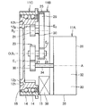
以下、本発明の実施の形態を、図面に基づき詳細に説明する。図1は、本発明の一実施形態になるインホイールモータ駆動装置を示す断面図である。図2および図3は、同実施形態から車輪ハブ軸受部を取り出して示す斜視図であり、図2が軸線方向一方側(車輪側)からみた状態を、図3が軸線方向他方側(車体側)からみた状態を表す。本実施形態のインホイールモータ駆動装置11は、モータ部11A、減速部11B、および車輪ハブ軸受部11Cを備える。車輪ハブ軸受部11Cは、回転部材であるハブ内輪12と、非回転部材であるハブ外輪13と、複数の転動体14を備える複列の転がり軸受である。ハブ外輪13はハブ内輪12の外周を包囲し、転動体14はハブ内輪12とハブ外輪13の間に形成される環状隙間に配置される。かかる環状隙間は、ハブ外輪13の両端部内周に設けられた環状のシール15で封止される。本実施形態の転動体14は玉であるが、その他の形状であってもよい。
Hereinafter, embodiments of the present invention will be described in detail with reference to the drawings. FIG. 1 is a cross-sectional view showing an in-wheel motor drive apparatus according to an embodiment of the present invention. 2 and 3 are perspective views showing the wheel hub bearing portion taken out from the embodiment. FIG. 2 shows a state when viewed from one axial side (wheel side), and FIG. 3 shows the other axial side (vehicle side). ) Represents the state. The in-wheel
ハブ内輪12の軸線O方向一方側には座面12pが形成される。座面12pは軸線Oに対し直角な環状の平坦面である。座面12pにはボルト孔12hが周方向に間隔を空けて複数形成される。各座面12pに図示しない車輪を当接させ、軸線O方向一方から図示しないボルトを車輪に差し込みつつ各ボルト孔12hに螺合することにより、ハブ内輪12の軸線O方向一方側には車輪が取付固定される。ハブ内輪12の内周には内歯歯車12gが設けられる。内歯歯車12gはハブ内輪12の軸線O方向他方側に配置される。以下の説明では、軸線Oに関し、座面12p側を軸線方向一方側とし、内歯歯車12g側を軸線方向他方側とする。
A
ハブ内輪12は、軸線O方向一方側に、ハブ内輪12の内部空間を閉塞する円板状の壁部12wと、壁部12wの中心に立設される軸部12sを有する。軸部12sは軸線Oに沿って延びる。ハブ内輪12の内部空間には、軸部12sを回転自在に支持する転がり軸受16が設けられる。転がり軸受16は減速部11Bの減速部ケーシング25に支持される。
The hub
減速部11Bは、外歯歯車21、中間軸22、入力歯車23、およびこれら回転要素を収容する減速部ケーシング25を有する平行軸式減速機である。外歯歯車21は中間軸22の一方端側に設けられ、入力歯車23は中間軸22の他方端側に設けられる。中間軸22の一方端は転がり軸受24を介して減速部ケーシング25に回転自在に支持される。中間軸22の他方端は転がり軸受26を介して減速部ケーシング25に回転自在に支持される。外歯歯車21は減速部11Bのファイナルギヤ、すなわち出力歯車である。外歯歯車21および入力歯車23は、転がり軸受24,26間に配置され、これら転がり軸受に両持ち支持される。
The
減速部ケーシング25の一方端領域は、ハブ外輪13の他方端に嵌合する。両者の嵌合隙間は、シール17によって封止される。シール17はハブ外輪13の全周に亘って延びる。減速部ケーシング25の一方端領域、中間軸22の一方端領域、外歯歯車21、および転がり軸受24はハブ内輪12の内部空間に配置される。相対的に小さな内径を有する外歯歯車21は相対的に大きな内径を有する内歯歯車12gと噛合する。減速部ケーシング25の他方端領域、中間軸22の他方端領域、入力歯車23、および転がり軸受26は、車輪ハブ軸受部11Cよりも軸線方向他方側に配置される。
One end region of the speed
外歯歯車21、中間軸22、および入力歯車23の軸線Bは、軸線Oと平行に延びる。つまり減速部11Bは、車輪ハブ軸受部11Cの軸線Oから直角方向にオフセットして配置される。減速部11Bの減速部ケーシング25は、前述したハブ外輪13と結合する。入力歯車23は外歯歯車21よりも大径の外歯歯車であり、モータ部11Aのモータ回転軸歯車38と噛合する。モータ回転軸歯車38は入力歯車23よりも小径である。このためモータ回転軸歯車38の回転は減速部11Bで減速されて、外歯歯車21からハブ内輪12へ伝達される。
The axis B of the
モータ部11Aは、車輪ハブ軸受部11Cの軸線O方向他方側に配置され、モータ本体31、モータ回転軸34、およびモータ回転軸歯車38を有する。モータ本体31は、軸線Aを中心とするロータ32およびステータ33と、これらロータ32およびステータ33を収容する円筒形状のモータ部ケーシング35を含む。モータ回転軸34はロータ32と結合し、モータ部ケーシング35の中心に配置される。軸線Aに沿って延びるモータ回転軸34の両端部は、転がり軸受36,37を介して、モータ部ケーシング35の両端部に回転自在に支持される。モータ回転軸34の端部は、モータ部ケーシング35から突出して車輪ハブ軸受部11Cに指向する。かかるモータ回転軸34の先端部外周にはモータ回転軸歯車38が設けられる。つまりモータ回転軸歯車38はモータ部ケーシング35の外部に配置される。これまで説明してきた転がり軸受16,24,26,36,37は深溝玉軸受であるが、他の構造の軸受であってもよい。
The
モータ部ケーシング35は減速部ケーシング25と結合する。軸線Oに関し、ハブ外輪13と、減速部ケーシング25と、モータ部ケーシング35は、この順序で配列される。モータ回転軸歯車38は、減速部ケーシング25に収容されて、入力歯車23と噛合する。
The
モータ部11Aの軸線A、減速部11Bの軸線B、および車輪ハブ軸受部11Cの軸線Oは、互いにオフセットして平行配置される。モータ部11Aと減速部11Bは、軸線Oを中心として、互いに異なる周方向位置に配置される。またモータ部11A、減速部11B、および車輪ハブ軸受部11Cはこの順序で軸線方向に配列する。インホイールモータ駆動装置11は電動車両の車幅方向両側に配置され、軸線Oは電動車両の車幅方向に延びる。そして車輪ハブ軸受部11Cは車幅方向外側に配置される。またモータ部11Aは車幅方向内側に配置される。
The axis A of the
ハブ内輪12とモータ部ケーシング35の間に介在する大径の入力歯車23は、ハブ内輪12の軸線Oからみて軸線直角方向一方側にオフセットして配置されることから、軸線Oからみて軸線直角方向他方側に空間が残される。かかる空間には小径のモータ回転軸歯車38および端子箱39が配置される。端子箱39は、モータ本体31に隣接して配置され、ステータ33のコイルから延びる電気導線と接続する。端子箱39はハブ外輪13の外周面よりも径方向内側に配置される。端子箱39には、インホイールモータ駆動装置11の外部電源から延びる電力線(図示せず)が差し込み固定される。外部電源から端子箱39を経てモータ部11Aのステータ33に電力が供給されると、モータ回転軸34が回転し、この回転が減速部11Bで減速されてハブ内輪12に伝達され、ハブ内輪12が回転する。
Since the large-
ところで本実施形態によれば車輪ハブ軸受部11Cが、車輪と連結するための座面12pおよびボルト孔12h(車輪連結部)を軸線方向一方側に有するハブ内輪12、ハブ内輪12の外周を包囲するハブ外輪13、およびハブ内輪12とハブ外輪13の間に形成される環状隙間に配置される複数の転動体14、およびハブ内輪12の内周に設けられる大径の内歯歯車12gを含む。また小径の外歯歯車21はハブ内輪12の内部空間に配置されて内歯歯車12gと噛合する。そしてモータ部11Aは、ハブ内輪12の軸線Oに関し、車輪ハブ軸受部11Cの軸線方向他方側で、軸線直角方向にオフセットして配置され、外歯歯車21を駆動する。このためモータ部と車輪ハブ軸受部が同軸かつ直列に配置される従来のインホイールモータと比較して、インホイールモータ駆動装置11の軸線方向寸法を短くすることができる。
By the way, according to the present embodiment, the wheel
また本実施形態によれば減速部11Bが外歯歯車21を含むことから、減速部11Bと車輪ハブ軸受部11Cが軸線方向に重なるよう配置される。したがってインホイールモータ駆動装置11の軸線方向寸法を従来よりも短くすることができる。
Moreover, according to this embodiment, since the
また本実施形態によればモータ部11Aは、ロータ32およびステータ33を収容するモータ本体31、ロータ32と結合する部材であってモータ本体31から車輪ハブ軸受部11Cに向かって突出するモータ回転軸34、およびモータ回転軸34の先端部外周に設けられるモータ回転軸歯車38を含む。減速部11Bは、モータ回転軸歯車38よりも大径の外歯歯車であってモータ回転軸歯車38と噛合する入力歯車23、外歯歯車21および入力歯車23を同軸に結合する中間軸22を含む。そして入力歯車23は、ハブ内輪12の軸線O方向位置に関し車輪ハブ軸受部11Cとモータ本体31の間に配置される。これにより大径の入力歯車23を車輪ハブ軸受部11Cおよびモータ部11Aの間に配置し、小径の外歯歯車21および中間軸22を車輪ハブ軸受部11Cに重ねて配置することができ、インホイールモータ駆動装置11の軸線方向寸法を従来よりも小さくすることができる。
Further, according to the present embodiment, the
また本実施形態によればハブ内輪12の軸線方向位置に関し車輪ハブ軸受部11Cとモータ本体31の間に配置され、外部電源からモータ部11Aに電力を供給する電力線と接続するための端子箱39をさらに備える。これにより、車輪ハブ軸受部11Cとモータ本体31の間の空きスペースを有効に利用して、インホイールモータ駆動装置11の小型化を図ることができる。
Further, according to the present embodiment, the
次に本発明の他の実施形態を説明する。図4および図5は本発明の他の実施形態を示す模式図であって、図4が軸線直角方向にみた状態を、図5が軸線方向にみた状態を表す。他の実施形態につき、前述した実施形態と共通する構成については同一の符号を付して説明を省略し、異なる構成について以下に説明する。他の実施形態では、減速部11Bがモータ回転軸歯車38よりも大径の外歯歯車であって噛合箇所E1でモータ回転軸歯車38と噛合する入力歯車23、一方端側が入力歯車23の中心と結合する第1中間軸27、第1中間軸27の他方端側と結合する第1中間歯車28、噛合箇所E2で第1中間歯車28と噛合する第2中間歯車29、一方端側が第2中間歯車29と結合し、他方端側が第2中間歯車29の回転を外歯歯車21に伝達する第2中間軸30をさらに含む。
Next, another embodiment of the present invention will be described. 4 and 5 are schematic views showing another embodiment of the present invention. FIG. 4 shows a state when viewed in the direction perpendicular to the axis, and FIG. 5 shows a state when viewed in the direction of the axis. Regarding the other embodiments, the same reference numerals are given to the configurations common to the above-described embodiments, and the description thereof will be omitted, and different configurations will be described below. In other embodiments, the
第1中間歯車28は相対的に小径の外歯歯車である。第2中間歯車29は相対的に大径の外歯歯車である。また第2中間歯車29は減速部出力側の外歯歯車21よりも大径にされる。外歯歯車21は噛合箇所E3で内歯歯車12gと噛合する。図5に示すように軸線方向にみて第2中間歯車29はハブ内輪12と重なる。ただし図4に示すように第1中間歯車28および第2中間歯車29は、軸線方向位置が重ならないよう、車輪ハブ軸受部11Cとモータ本体31の間に配置される。入力歯車23、第1中間軸27、および第1中間歯車28の軸線B1は、軸線Oと一致するか、あるいは軸線Oに近い位置でオフセットして平行に延びる。第2中間歯車29、第2中間軸30、および外歯歯車21の軸線B2は、軸線Oから遠い位置でオフセットして平行に延びる。軸線B1,B2は、モータ部11Aの軸線からもオフセットして平行に延びる。
The first
他の実施形態によれば、減速部11Bの出力歯車になる外歯歯車21および入力歯車23が、軸線O方向位置に関し車輪ハブ軸受部11Cと重なるように配置されることから、インホイールモータ駆動装置11の軸線方向寸法を従来よりも小さくすることができる。
According to another embodiment, since the
以上、図面を参照してこの発明の実施の形態を説明したが、この発明は、図示した実施の形態のものに限定されない。図示した実施の形態に対して、この発明と同一の範囲内において、あるいは均等の範囲内において、種々の修正や変形を加えることが可能である。 Although the embodiments of the present invention have been described with reference to the drawings, the present invention is not limited to the illustrated embodiments. Various modifications and variations can be made to the illustrated embodiment within the same range or equivalent range as the present invention.
この発明になるインホイールモータ駆動装置は、電気自動車およびハイブリッド車両において有利に利用される。 The in-wheel motor drive device according to the present invention is advantageously used in electric vehicles and hybrid vehicles.
11 インホイールモータ駆動装置、 11A モータ部、
11B 減速部、 11C 車輪ハブ軸受部、 12 ハブ内輪、
12g 内歯歯車、 12h ボルト孔(車輪連結部)、
12p 座面(車輪連結部)、 12s 軸部、 12w 壁部、
13 ハブ外輪、 14 転動体、 15 シール、
21 外歯歯車(減速部出力歯車)、 22 中間軸、
23 入力歯車(減速部入力歯車)、 25 減速部ケーシング、
27 第1中間軸、 28 第1中間歯車、 29 第2中間歯車、
30 第2中間軸、 31 モータ本体、 32 ロータ、
33 ステータ、 34 モータ回転軸、
35 モータ部ケーシング、 38 モータ回転軸歯車、 39 端子箱。
11 In-wheel motor drive device, 11A motor part,
11B Deceleration part, 11C Wheel hub bearing part, 12 Hub inner ring,
12g internal gear, 12h bolt hole (wheel connecting part),
12p seating surface (wheel connecting part), 12s shaft part, 12w wall part,
13 hub outer ring, 14 rolling element, 15 seal,
21 external gear (speed reducer output gear), 22 intermediate shaft,
23 input gear (speed reducer input gear), 25 speed reducer casing,
27 first intermediate shaft, 28 first intermediate gear, 29 second intermediate gear,
30 second intermediate shaft, 31 motor body, 32 rotor,
33 Stator, 34 Motor rotating shaft,
35 Motor casing, 38 Motor rotating shaft gear, 39 Terminal box.
Claims (5)
前記ハブ内輪の内部空間に配置されて、前記ハブ内輪の内周に設けられる大径の内歯歯車と噛合する小径の外歯歯車と、
前記車輪ハブ軸受部の軸線方向他方側に配置され、前記外歯歯車を駆動するモータ部とを備え、
前記モータ部は前記車輪ハブ軸受部の軸線から軸線直角方向にオフセットして配置される、インホイールモータ駆動装置。 A hub inner ring having a wheel coupling portion for coupling with a wheel on one side in the axial direction, a hub outer ring surrounding an outer periphery of the hub inner ring, and an annular gap formed between the hub inner ring and the hub outer ring A wheel hub bearing portion including a plurality of rolling elements;
A small-diameter external gear that is disposed in the internal space of the hub inner ring and meshes with a large-diameter internal gear provided on the inner periphery of the hub inner ring;
A motor part that is disposed on the other side in the axial direction of the wheel hub bearing part and that drives the external gear;
The in-wheel motor drive device, wherein the motor unit is arranged offset from the axis of the wheel hub bearing unit in a direction perpendicular to the axis.
前記減速部は、前記モータ回転軸歯車よりも大径の外歯歯車であって前記モータ回転軸歯車と噛合する入力歯車、および前記入力歯車と前記出力歯車を同軸に結合する中間軸をさらに含み、
前記入力歯車は、前記ハブ内輪の軸線方向位置に関し前記車輪ハブ軸受部と前記モータ本体の間に配置される、請求項2に記載のインホイールモータ駆動装置。 The motor unit includes a motor main body that houses a rotor and a stator, a motor coupling shaft that is a member coupled to the rotor and projects from the motor main body toward the wheel hub bearing unit, and an outer periphery of a tip end portion of the motor rotation shaft Including a motor rotating shaft gear provided in
The speed reduction unit further includes an input gear that is an external gear having a larger diameter than the motor rotation shaft gear and meshes with the motor rotation shaft gear, and an intermediate shaft that coaxially couples the input gear and the output gear. ,
The in-wheel motor drive device according to claim 2, wherein the input gear is disposed between the wheel hub bearing portion and the motor main body with respect to an axial direction position of the hub inner ring.
前記減速部は、該モータ回転軸歯車よりも大径の外歯歯車であって前記モータ回転軸歯車と噛合する入力歯車、一方端側が前記入力歯車の中心と結合する第1中間軸、前記第1中間軸の他方端側と結合する第1中間歯車、前記第1中間歯車と噛合する第2中間歯車、一方端側が前記第2中間歯車と結合し、他方端側が前記第2中間歯車の回転を前記出力歯車に伝達する第2中間軸をさらに含み、
前記第1中間歯車および前記第2中間歯車は、前記ハブ内輪の軸線方向位置に関し前記車輪ハブ軸受部と前記モータ本体の間に配置される、請求項2に記載のインホイールモータ駆動装置。 The motor unit includes a motor main body that houses a rotor and a stator, a motor coupling shaft that is a member coupled to the rotor and projects from the motor main body toward the wheel hub bearing unit, and an outer periphery of a tip end portion of the motor rotation shaft Including a motor rotating shaft gear provided in
The speed reducer is an external gear having a larger diameter than the motor rotation shaft gear and meshes with the motor rotation shaft gear, a first intermediate shaft whose one end side is coupled to the center of the input gear, the first gear A first intermediate gear coupled to the other end side of one intermediate shaft, a second intermediate gear meshing with the first intermediate gear, one end side coupled to the second intermediate gear, and the other end side rotating the second intermediate gear Further including a second intermediate shaft for transmitting to the output gear;
The in-wheel motor drive device according to claim 2, wherein the first intermediate gear and the second intermediate gear are disposed between the wheel hub bearing portion and the motor main body with respect to an axial position of the hub inner ring.
Priority Applications (2)
| Application Number | Priority Date | Filing Date | Title |
|---|---|---|---|
| JP2015133742A JP2017013682A (en) | 2015-07-02 | 2015-07-02 | In-wheel motor drive device |
| PCT/JP2016/067640 WO2017002603A1 (en) | 2015-07-02 | 2016-06-14 | In-wheel motor drive device |
Applications Claiming Priority (1)
| Application Number | Priority Date | Filing Date | Title |
|---|---|---|---|
| JP2015133742A JP2017013682A (en) | 2015-07-02 | 2015-07-02 | In-wheel motor drive device |
Publications (1)
| Publication Number | Publication Date |
|---|---|
| JP2017013682A true JP2017013682A (en) | 2017-01-19 |
Family
ID=57608747
Family Applications (1)
| Application Number | Title | Priority Date | Filing Date |
|---|---|---|---|
| JP2015133742A Pending JP2017013682A (en) | 2015-07-02 | 2015-07-02 | In-wheel motor drive device |
Country Status (2)
| Country | Link |
|---|---|
| JP (1) | JP2017013682A (en) |
| WO (1) | WO2017002603A1 (en) |
Families Citing this family (1)
| Publication number | Priority date | Publication date | Assignee | Title |
|---|---|---|---|---|
| CN110154744A (en) * | 2018-02-13 | 2019-08-23 | Ntn株式会社 | In-wheel motor drive unit |
Family Cites Families (3)
| Publication number | Priority date | Publication date | Assignee | Title |
|---|---|---|---|---|
| JPS49107065U (en) * | 1973-01-12 | 1974-09-12 | ||
| JPS5887623U (en) * | 1981-12-10 | 1983-06-14 | 日産自動車株式会社 | Industrial vehicle drive system |
| JP5872360B2 (en) * | 2012-03-30 | 2016-03-01 | 本田技研工業株式会社 | Electric vehicle |
-
2015
- 2015-07-02 JP JP2015133742A patent/JP2017013682A/en active Pending
-
2016
- 2016-06-14 WO PCT/JP2016/067640 patent/WO2017002603A1/en active Application Filing
Also Published As
| Publication number | Publication date |
|---|---|
| WO2017002603A1 (en) | 2017-01-05 |
Similar Documents
| Publication | Publication Date | Title |
|---|---|---|
| US8142317B2 (en) | Power transmission apparatus of hybrid vehicle | |
| US20060079370A1 (en) | Differential device and drive power transmission unit using the same | |
| WO2012096310A1 (en) | Device for transmitting driving force of motors | |
| CN111120583B (en) | Speed reducer and electromechanical device | |
| JP2009023426A (en) | Drive device for hybrid vehicle | |
| JP2013181645A (en) | Drive unit for electric vehicle | |
| JP2019094932A (en) | Driving device for vehicle | |
| JP6160478B2 (en) | Drive device for hybrid vehicle | |
| WO2017026258A1 (en) | Motor driving device for vehicle | |
| JP6596897B2 (en) | Motor drive device | |
| US10744874B2 (en) | Hybrid vehicle and vehicle | |
| WO2015163183A1 (en) | Vehicle drive device | |
| JP2006015785A (en) | Driving device for electric automobile | |
| JP6781608B2 (en) | In-wheel motor drive | |
| JP2007159287A (en) | Motor support mechanism of drive unit for vehicle | |
| JP2008215550A (en) | Gear shifting mechanism and wheel driving device | |
| JP2003127682A (en) | Vehicle drive unit | |
| CN109842240B (en) | Power unit for a motor vehicle and axle power unit | |
| WO2017002603A1 (en) | In-wheel motor drive device | |
| JP2014084000A (en) | Vehicular drive device | |
| JP6903534B2 (en) | In-wheel motor drive | |
| JP2009107491A (en) | Drive unit for vehicle | |
| JP2017177964A (en) | Hybrid car and vehicle | |
| JP2017177965A (en) | Hybrid car and vehicle | |
| JP6800670B2 (en) | In-wheel motor drive |