JP6160478B2 - Drive device for hybrid vehicle - Google Patents
Drive device for hybrid vehicle Download PDFInfo
- Publication number
- JP6160478B2 JP6160478B2 JP2013269178A JP2013269178A JP6160478B2 JP 6160478 B2 JP6160478 B2 JP 6160478B2 JP 2013269178 A JP2013269178 A JP 2013269178A JP 2013269178 A JP2013269178 A JP 2013269178A JP 6160478 B2 JP6160478 B2 JP 6160478B2
- Authority
- JP
- Japan
- Prior art keywords
- shaft
- driven gear
- bearing
- output shaft
- bearing device
- Prior art date
- Legal status (The legal status is an assumption and is not a legal conclusion. Google has not performed a legal analysis and makes no representation as to the accuracy of the status listed.)
- Active
Links
Images


Classifications
-
- B—PERFORMING OPERATIONS; TRANSPORTING
- B60—VEHICLES IN GENERAL
- B60K—ARRANGEMENT OR MOUNTING OF PROPULSION UNITS OR OF TRANSMISSIONS IN VEHICLES; ARRANGEMENT OR MOUNTING OF PLURAL DIVERSE PRIME-MOVERS IN VEHICLES; AUXILIARY DRIVES FOR VEHICLES; INSTRUMENTATION OR DASHBOARDS FOR VEHICLES; ARRANGEMENTS IN CONNECTION WITH COOLING, AIR INTAKE, GAS EXHAUST OR FUEL SUPPLY OF PROPULSION UNITS IN VEHICLES
- B60K6/00—Arrangement or mounting of plural diverse prime-movers for mutual or common propulsion, e.g. hybrid propulsion systems comprising electric motors and internal combustion engines ; Control systems therefor, i.e. systems controlling two or more prime movers, or controlling one of these prime movers and any of the transmission, drive or drive units Informative references: mechanical gearings with secondary electric drive F16H3/72; arrangements for handling mechanical energy structurally associated with the dynamo-electric machine H02K7/00; machines comprising structurally interrelated motor and generator parts H02K51/00; dynamo-electric machines not otherwise provided for in H02K see H02K99/00
- B60K6/20—Arrangement or mounting of plural diverse prime-movers for mutual or common propulsion, e.g. hybrid propulsion systems comprising electric motors and internal combustion engines ; Control systems therefor, i.e. systems controlling two or more prime movers, or controlling one of these prime movers and any of the transmission, drive or drive units Informative references: mechanical gearings with secondary electric drive F16H3/72; arrangements for handling mechanical energy structurally associated with the dynamo-electric machine H02K7/00; machines comprising structurally interrelated motor and generator parts H02K51/00; dynamo-electric machines not otherwise provided for in H02K see H02K99/00 the prime-movers consisting of electric motors and internal combustion engines, e.g. HEVs
- B60K6/42—Arrangement or mounting of plural diverse prime-movers for mutual or common propulsion, e.g. hybrid propulsion systems comprising electric motors and internal combustion engines ; Control systems therefor, i.e. systems controlling two or more prime movers, or controlling one of these prime movers and any of the transmission, drive or drive units Informative references: mechanical gearings with secondary electric drive F16H3/72; arrangements for handling mechanical energy structurally associated with the dynamo-electric machine H02K7/00; machines comprising structurally interrelated motor and generator parts H02K51/00; dynamo-electric machines not otherwise provided for in H02K see H02K99/00 the prime-movers consisting of electric motors and internal combustion engines, e.g. HEVs characterised by the architecture of the hybrid electric vehicle
- B60K6/44—Series-parallel type
- B60K6/445—Differential gearing distribution type
-
- B—PERFORMING OPERATIONS; TRANSPORTING
- B60—VEHICLES IN GENERAL
- B60K—ARRANGEMENT OR MOUNTING OF PROPULSION UNITS OR OF TRANSMISSIONS IN VEHICLES; ARRANGEMENT OR MOUNTING OF PLURAL DIVERSE PRIME-MOVERS IN VEHICLES; AUXILIARY DRIVES FOR VEHICLES; INSTRUMENTATION OR DASHBOARDS FOR VEHICLES; ARRANGEMENTS IN CONNECTION WITH COOLING, AIR INTAKE, GAS EXHAUST OR FUEL SUPPLY OF PROPULSION UNITS IN VEHICLES
- B60K6/00—Arrangement or mounting of plural diverse prime-movers for mutual or common propulsion, e.g. hybrid propulsion systems comprising electric motors and internal combustion engines ; Control systems therefor, i.e. systems controlling two or more prime movers, or controlling one of these prime movers and any of the transmission, drive or drive units Informative references: mechanical gearings with secondary electric drive F16H3/72; arrangements for handling mechanical energy structurally associated with the dynamo-electric machine H02K7/00; machines comprising structurally interrelated motor and generator parts H02K51/00; dynamo-electric machines not otherwise provided for in H02K see H02K99/00
- B60K6/20—Arrangement or mounting of plural diverse prime-movers for mutual or common propulsion, e.g. hybrid propulsion systems comprising electric motors and internal combustion engines ; Control systems therefor, i.e. systems controlling two or more prime movers, or controlling one of these prime movers and any of the transmission, drive or drive units Informative references: mechanical gearings with secondary electric drive F16H3/72; arrangements for handling mechanical energy structurally associated with the dynamo-electric machine H02K7/00; machines comprising structurally interrelated motor and generator parts H02K51/00; dynamo-electric machines not otherwise provided for in H02K see H02K99/00 the prime-movers consisting of electric motors and internal combustion engines, e.g. HEVs
- B60K6/22—Arrangement or mounting of plural diverse prime-movers for mutual or common propulsion, e.g. hybrid propulsion systems comprising electric motors and internal combustion engines ; Control systems therefor, i.e. systems controlling two or more prime movers, or controlling one of these prime movers and any of the transmission, drive or drive units Informative references: mechanical gearings with secondary electric drive F16H3/72; arrangements for handling mechanical energy structurally associated with the dynamo-electric machine H02K7/00; machines comprising structurally interrelated motor and generator parts H02K51/00; dynamo-electric machines not otherwise provided for in H02K see H02K99/00 the prime-movers consisting of electric motors and internal combustion engines, e.g. HEVs characterised by apparatus, components or means specially adapted for HEVs
- B60K6/26—Arrangement or mounting of plural diverse prime-movers for mutual or common propulsion, e.g. hybrid propulsion systems comprising electric motors and internal combustion engines ; Control systems therefor, i.e. systems controlling two or more prime movers, or controlling one of these prime movers and any of the transmission, drive or drive units Informative references: mechanical gearings with secondary electric drive F16H3/72; arrangements for handling mechanical energy structurally associated with the dynamo-electric machine H02K7/00; machines comprising structurally interrelated motor and generator parts H02K51/00; dynamo-electric machines not otherwise provided for in H02K see H02K99/00 the prime-movers consisting of electric motors and internal combustion engines, e.g. HEVs characterised by apparatus, components or means specially adapted for HEVs characterised by the motors or the generators
-
- B—PERFORMING OPERATIONS; TRANSPORTING
- B60—VEHICLES IN GENERAL
- B60K—ARRANGEMENT OR MOUNTING OF PROPULSION UNITS OR OF TRANSMISSIONS IN VEHICLES; ARRANGEMENT OR MOUNTING OF PLURAL DIVERSE PRIME-MOVERS IN VEHICLES; AUXILIARY DRIVES FOR VEHICLES; INSTRUMENTATION OR DASHBOARDS FOR VEHICLES; ARRANGEMENTS IN CONNECTION WITH COOLING, AIR INTAKE, GAS EXHAUST OR FUEL SUPPLY OF PROPULSION UNITS IN VEHICLES
- B60K6/00—Arrangement or mounting of plural diverse prime-movers for mutual or common propulsion, e.g. hybrid propulsion systems comprising electric motors and internal combustion engines ; Control systems therefor, i.e. systems controlling two or more prime movers, or controlling one of these prime movers and any of the transmission, drive or drive units Informative references: mechanical gearings with secondary electric drive F16H3/72; arrangements for handling mechanical energy structurally associated with the dynamo-electric machine H02K7/00; machines comprising structurally interrelated motor and generator parts H02K51/00; dynamo-electric machines not otherwise provided for in H02K see H02K99/00
- B60K6/20—Arrangement or mounting of plural diverse prime-movers for mutual or common propulsion, e.g. hybrid propulsion systems comprising electric motors and internal combustion engines ; Control systems therefor, i.e. systems controlling two or more prime movers, or controlling one of these prime movers and any of the transmission, drive or drive units Informative references: mechanical gearings with secondary electric drive F16H3/72; arrangements for handling mechanical energy structurally associated with the dynamo-electric machine H02K7/00; machines comprising structurally interrelated motor and generator parts H02K51/00; dynamo-electric machines not otherwise provided for in H02K see H02K99/00 the prime-movers consisting of electric motors and internal combustion engines, e.g. HEVs
- B60K6/22—Arrangement or mounting of plural diverse prime-movers for mutual or common propulsion, e.g. hybrid propulsion systems comprising electric motors and internal combustion engines ; Control systems therefor, i.e. systems controlling two or more prime movers, or controlling one of these prime movers and any of the transmission, drive or drive units Informative references: mechanical gearings with secondary electric drive F16H3/72; arrangements for handling mechanical energy structurally associated with the dynamo-electric machine H02K7/00; machines comprising structurally interrelated motor and generator parts H02K51/00; dynamo-electric machines not otherwise provided for in H02K see H02K99/00 the prime-movers consisting of electric motors and internal combustion engines, e.g. HEVs characterised by apparatus, components or means specially adapted for HEVs
- B60K6/36—Arrangement or mounting of plural diverse prime-movers for mutual or common propulsion, e.g. hybrid propulsion systems comprising electric motors and internal combustion engines ; Control systems therefor, i.e. systems controlling two or more prime movers, or controlling one of these prime movers and any of the transmission, drive or drive units Informative references: mechanical gearings with secondary electric drive F16H3/72; arrangements for handling mechanical energy structurally associated with the dynamo-electric machine H02K7/00; machines comprising structurally interrelated motor and generator parts H02K51/00; dynamo-electric machines not otherwise provided for in H02K see H02K99/00 the prime-movers consisting of electric motors and internal combustion engines, e.g. HEVs characterised by apparatus, components or means specially adapted for HEVs characterised by the transmission gearings
- B60K6/365—Arrangement or mounting of plural diverse prime-movers for mutual or common propulsion, e.g. hybrid propulsion systems comprising electric motors and internal combustion engines ; Control systems therefor, i.e. systems controlling two or more prime movers, or controlling one of these prime movers and any of the transmission, drive or drive units Informative references: mechanical gearings with secondary electric drive F16H3/72; arrangements for handling mechanical energy structurally associated with the dynamo-electric machine H02K7/00; machines comprising structurally interrelated motor and generator parts H02K51/00; dynamo-electric machines not otherwise provided for in H02K see H02K99/00 the prime-movers consisting of electric motors and internal combustion engines, e.g. HEVs characterised by apparatus, components or means specially adapted for HEVs characterised by the transmission gearings with the gears having orbital motion
-
- B—PERFORMING OPERATIONS; TRANSPORTING
- B60—VEHICLES IN GENERAL
- B60K—ARRANGEMENT OR MOUNTING OF PROPULSION UNITS OR OF TRANSMISSIONS IN VEHICLES; ARRANGEMENT OR MOUNTING OF PLURAL DIVERSE PRIME-MOVERS IN VEHICLES; AUXILIARY DRIVES FOR VEHICLES; INSTRUMENTATION OR DASHBOARDS FOR VEHICLES; ARRANGEMENTS IN CONNECTION WITH COOLING, AIR INTAKE, GAS EXHAUST OR FUEL SUPPLY OF PROPULSION UNITS IN VEHICLES
- B60K6/00—Arrangement or mounting of plural diverse prime-movers for mutual or common propulsion, e.g. hybrid propulsion systems comprising electric motors and internal combustion engines ; Control systems therefor, i.e. systems controlling two or more prime movers, or controlling one of these prime movers and any of the transmission, drive or drive units Informative references: mechanical gearings with secondary electric drive F16H3/72; arrangements for handling mechanical energy structurally associated with the dynamo-electric machine H02K7/00; machines comprising structurally interrelated motor and generator parts H02K51/00; dynamo-electric machines not otherwise provided for in H02K see H02K99/00
- B60K6/20—Arrangement or mounting of plural diverse prime-movers for mutual or common propulsion, e.g. hybrid propulsion systems comprising electric motors and internal combustion engines ; Control systems therefor, i.e. systems controlling two or more prime movers, or controlling one of these prime movers and any of the transmission, drive or drive units Informative references: mechanical gearings with secondary electric drive F16H3/72; arrangements for handling mechanical energy structurally associated with the dynamo-electric machine H02K7/00; machines comprising structurally interrelated motor and generator parts H02K51/00; dynamo-electric machines not otherwise provided for in H02K see H02K99/00 the prime-movers consisting of electric motors and internal combustion engines, e.g. HEVs
- B60K6/22—Arrangement or mounting of plural diverse prime-movers for mutual or common propulsion, e.g. hybrid propulsion systems comprising electric motors and internal combustion engines ; Control systems therefor, i.e. systems controlling two or more prime movers, or controlling one of these prime movers and any of the transmission, drive or drive units Informative references: mechanical gearings with secondary electric drive F16H3/72; arrangements for handling mechanical energy structurally associated with the dynamo-electric machine H02K7/00; machines comprising structurally interrelated motor and generator parts H02K51/00; dynamo-electric machines not otherwise provided for in H02K see H02K99/00 the prime-movers consisting of electric motors and internal combustion engines, e.g. HEVs characterised by apparatus, components or means specially adapted for HEVs
- B60K6/40—Arrangement or mounting of plural diverse prime-movers for mutual or common propulsion, e.g. hybrid propulsion systems comprising electric motors and internal combustion engines ; Control systems therefor, i.e. systems controlling two or more prime movers, or controlling one of these prime movers and any of the transmission, drive or drive units Informative references: mechanical gearings with secondary electric drive F16H3/72; arrangements for handling mechanical energy structurally associated with the dynamo-electric machine H02K7/00; machines comprising structurally interrelated motor and generator parts H02K51/00; dynamo-electric machines not otherwise provided for in H02K see H02K99/00 the prime-movers consisting of electric motors and internal combustion engines, e.g. HEVs characterised by apparatus, components or means specially adapted for HEVs characterised by the assembly or relative disposition of components
-
- F—MECHANICAL ENGINEERING; LIGHTING; HEATING; WEAPONS; BLASTING
- F16—ENGINEERING ELEMENTS AND UNITS; GENERAL MEASURES FOR PRODUCING AND MAINTAINING EFFECTIVE FUNCTIONING OF MACHINES OR INSTALLATIONS; THERMAL INSULATION IN GENERAL
- F16H—GEARING
- F16H1/00—Toothed gearings for conveying rotary motion
- F16H1/28—Toothed gearings for conveying rotary motion with gears having orbital motion
-
- F—MECHANICAL ENGINEERING; LIGHTING; HEATING; WEAPONS; BLASTING
- F16—ENGINEERING ELEMENTS AND UNITS; GENERAL MEASURES FOR PRODUCING AND MAINTAINING EFFECTIVE FUNCTIONING OF MACHINES OR INSTALLATIONS; THERMAL INSULATION IN GENERAL
- F16H—GEARING
- F16H3/00—Toothed gearings for conveying rotary motion with variable gear ratio or for reversing rotary motion
- F16H3/44—Toothed gearings for conveying rotary motion with variable gear ratio or for reversing rotary motion using gears having orbital motion
- F16H3/72—Toothed gearings for conveying rotary motion with variable gear ratio or for reversing rotary motion using gears having orbital motion with a secondary drive, e.g. regulating motor, in order to vary speed continuously
- F16H3/727—Toothed gearings for conveying rotary motion with variable gear ratio or for reversing rotary motion using gears having orbital motion with a secondary drive, e.g. regulating motor, in order to vary speed continuously with at least two dynamo electric machines for creating an electric power path inside the gearing, e.g. using generator and motor for a variable power torque path
- F16H3/728—Toothed gearings for conveying rotary motion with variable gear ratio or for reversing rotary motion using gears having orbital motion with a secondary drive, e.g. regulating motor, in order to vary speed continuously with at least two dynamo electric machines for creating an electric power path inside the gearing, e.g. using generator and motor for a variable power torque path with means to change ratio in the mechanical gearing
-
- F—MECHANICAL ENGINEERING; LIGHTING; HEATING; WEAPONS; BLASTING
- F16—ENGINEERING ELEMENTS AND UNITS; GENERAL MEASURES FOR PRODUCING AND MAINTAINING EFFECTIVE FUNCTIONING OF MACHINES OR INSTALLATIONS; THERMAL INSULATION IN GENERAL
- F16H—GEARING
- F16H37/00—Combinations of mechanical gearings, not provided for in groups F16H1/00 - F16H35/00
- F16H37/02—Combinations of mechanical gearings, not provided for in groups F16H1/00 - F16H35/00 comprising essentially only toothed or friction gearings
- F16H37/06—Combinations of mechanical gearings, not provided for in groups F16H1/00 - F16H35/00 comprising essentially only toothed or friction gearings with a plurality of driving or driven shafts; with arrangements for dividing torque between two or more intermediate shafts
- F16H37/08—Combinations of mechanical gearings, not provided for in groups F16H1/00 - F16H35/00 comprising essentially only toothed or friction gearings with a plurality of driving or driven shafts; with arrangements for dividing torque between two or more intermediate shafts with differential gearing
- F16H37/0833—Combinations of mechanical gearings, not provided for in groups F16H1/00 - F16H35/00 comprising essentially only toothed or friction gearings with a plurality of driving or driven shafts; with arrangements for dividing torque between two or more intermediate shafts with differential gearing with arrangements for dividing torque between two or more intermediate shafts, i.e. with two or more internal power paths
-
- F—MECHANICAL ENGINEERING; LIGHTING; HEATING; WEAPONS; BLASTING
- F16—ENGINEERING ELEMENTS AND UNITS; GENERAL MEASURES FOR PRODUCING AND MAINTAINING EFFECTIVE FUNCTIONING OF MACHINES OR INSTALLATIONS; THERMAL INSULATION IN GENERAL
- F16H—GEARING
- F16H57/00—General details of gearing
- F16H57/02—Gearboxes; Mounting gearing therein
- F16H57/021—Shaft support structures, e.g. partition walls, bearing eyes, casing walls or covers with bearings
-
- B—PERFORMING OPERATIONS; TRANSPORTING
- B60—VEHICLES IN GENERAL
- B60Y—INDEXING SCHEME RELATING TO ASPECTS CROSS-CUTTING VEHICLE TECHNOLOGY
- B60Y2200/00—Type of vehicle
- B60Y2200/90—Vehicles comprising electric prime movers
- B60Y2200/92—Hybrid vehicles
-
- B—PERFORMING OPERATIONS; TRANSPORTING
- B60—VEHICLES IN GENERAL
- B60Y—INDEXING SCHEME RELATING TO ASPECTS CROSS-CUTTING VEHICLE TECHNOLOGY
- B60Y2400/00—Special features of vehicle units
- B60Y2400/70—Gearings
- B60Y2400/73—Planetary gearings
-
- B—PERFORMING OPERATIONS; TRANSPORTING
- B60—VEHICLES IN GENERAL
- B60Y—INDEXING SCHEME RELATING TO ASPECTS CROSS-CUTTING VEHICLE TECHNOLOGY
- B60Y2400/00—Special features of vehicle units
- B60Y2400/80—Differentials
-
- F—MECHANICAL ENGINEERING; LIGHTING; HEATING; WEAPONS; BLASTING
- F16—ENGINEERING ELEMENTS AND UNITS; GENERAL MEASURES FOR PRODUCING AND MAINTAINING EFFECTIVE FUNCTIONING OF MACHINES OR INSTALLATIONS; THERMAL INSULATION IN GENERAL
- F16H—GEARING
- F16H37/00—Combinations of mechanical gearings, not provided for in groups F16H1/00 - F16H35/00
- F16H37/02—Combinations of mechanical gearings, not provided for in groups F16H1/00 - F16H35/00 comprising essentially only toothed or friction gearings
- F16H37/06—Combinations of mechanical gearings, not provided for in groups F16H1/00 - F16H35/00 comprising essentially only toothed or friction gearings with a plurality of driving or driven shafts; with arrangements for dividing torque between two or more intermediate shafts
- F16H37/08—Combinations of mechanical gearings, not provided for in groups F16H1/00 - F16H35/00 comprising essentially only toothed or friction gearings with a plurality of driving or driven shafts; with arrangements for dividing torque between two or more intermediate shafts with differential gearing
- F16H37/0833—Combinations of mechanical gearings, not provided for in groups F16H1/00 - F16H35/00 comprising essentially only toothed or friction gearings with a plurality of driving or driven shafts; with arrangements for dividing torque between two or more intermediate shafts with differential gearing with arrangements for dividing torque between two or more intermediate shafts, i.e. with two or more internal power paths
- F16H37/084—Combinations of mechanical gearings, not provided for in groups F16H1/00 - F16H35/00 comprising essentially only toothed or friction gearings with a plurality of driving or driven shafts; with arrangements for dividing torque between two or more intermediate shafts with differential gearing with arrangements for dividing torque between two or more intermediate shafts, i.e. with two or more internal power paths at least one power path being a continuously variable transmission, i.e. CVT
- F16H2037/0866—Power split variators with distributing differentials, with the output of the CVT connected or connectable to the output shaft
- F16H2037/0873—Power split variators with distributing differentials, with the output of the CVT connected or connectable to the output shaft with switching, e.g. to change ranges
-
- F—MECHANICAL ENGINEERING; LIGHTING; HEATING; WEAPONS; BLASTING
- F16—ENGINEERING ELEMENTS AND UNITS; GENERAL MEASURES FOR PRODUCING AND MAINTAINING EFFECTIVE FUNCTIONING OF MACHINES OR INSTALLATIONS; THERMAL INSULATION IN GENERAL
- F16H—GEARING
- F16H57/00—General details of gearing
- F16H57/02—Gearboxes; Mounting gearing therein
- F16H2057/02034—Gearboxes combined or connected with electric machines
-
- F—MECHANICAL ENGINEERING; LIGHTING; HEATING; WEAPONS; BLASTING
- F16—ENGINEERING ELEMENTS AND UNITS; GENERAL MEASURES FOR PRODUCING AND MAINTAINING EFFECTIVE FUNCTIONING OF MACHINES OR INSTALLATIONS; THERMAL INSULATION IN GENERAL
- F16H—GEARING
- F16H57/00—General details of gearing
- F16H57/02—Gearboxes; Mounting gearing therein
- F16H2057/02039—Gearboxes for particular applications
- F16H2057/02043—Gearboxes for particular applications for vehicle transmissions
-
- F—MECHANICAL ENGINEERING; LIGHTING; HEATING; WEAPONS; BLASTING
- F16—ENGINEERING ELEMENTS AND UNITS; GENERAL MEASURES FOR PRODUCING AND MAINTAINING EFFECTIVE FUNCTIONING OF MACHINES OR INSTALLATIONS; THERMAL INSULATION IN GENERAL
- F16H—GEARING
- F16H2200/00—Transmissions for multiple ratios
- F16H2200/20—Transmissions using gears with orbital motion
- F16H2200/2002—Transmissions using gears with orbital motion characterised by the number of sets of orbital gears
- F16H2200/2005—Transmissions using gears with orbital motion characterised by the number of sets of orbital gears with one sets of orbital gears
-
- F—MECHANICAL ENGINEERING; LIGHTING; HEATING; WEAPONS; BLASTING
- F16—ENGINEERING ELEMENTS AND UNITS; GENERAL MEASURES FOR PRODUCING AND MAINTAINING EFFECTIVE FUNCTIONING OF MACHINES OR INSTALLATIONS; THERMAL INSULATION IN GENERAL
- F16H—GEARING
- F16H2200/00—Transmissions for multiple ratios
- F16H2200/20—Transmissions using gears with orbital motion
- F16H2200/203—Transmissions using gears with orbital motion characterised by the engaging friction means not of the freewheel type, e.g. friction clutches or brakes
- F16H2200/2064—Transmissions using gears with orbital motion characterised by the engaging friction means not of the freewheel type, e.g. friction clutches or brakes using at least one positive clutch, e.g. dog clutch
-
- Y—GENERAL TAGGING OF NEW TECHNOLOGICAL DEVELOPMENTS; GENERAL TAGGING OF CROSS-SECTIONAL TECHNOLOGIES SPANNING OVER SEVERAL SECTIONS OF THE IPC; TECHNICAL SUBJECTS COVERED BY FORMER USPC CROSS-REFERENCE ART COLLECTIONS [XRACs] AND DIGESTS
- Y02—TECHNOLOGIES OR APPLICATIONS FOR MITIGATION OR ADAPTATION AGAINST CLIMATE CHANGE
- Y02T—CLIMATE CHANGE MITIGATION TECHNOLOGIES RELATED TO TRANSPORTATION
- Y02T10/00—Road transport of goods or passengers
- Y02T10/60—Other road transportation technologies with climate change mitigation effect
- Y02T10/62—Hybrid vehicles
-
- Y—GENERAL TAGGING OF NEW TECHNOLOGICAL DEVELOPMENTS; GENERAL TAGGING OF CROSS-SECTIONAL TECHNOLOGIES SPANNING OVER SEVERAL SECTIONS OF THE IPC; TECHNICAL SUBJECTS COVERED BY FORMER USPC CROSS-REFERENCE ART COLLECTIONS [XRACs] AND DIGESTS
- Y10—TECHNICAL SUBJECTS COVERED BY FORMER USPC
- Y10S—TECHNICAL SUBJECTS COVERED BY FORMER USPC CROSS-REFERENCE ART COLLECTIONS [XRACs] AND DIGESTS
- Y10S903/00—Hybrid electric vehicles, HEVS
- Y10S903/902—Prime movers comprising electrical and internal combustion motors
- Y10S903/903—Prime movers comprising electrical and internal combustion motors having energy storing means, e.g. battery, capacitor
- Y10S903/904—Component specially adapted for hev
- Y10S903/906—Motor or generator
-
- Y—GENERAL TAGGING OF NEW TECHNOLOGICAL DEVELOPMENTS; GENERAL TAGGING OF CROSS-SECTIONAL TECHNOLOGIES SPANNING OVER SEVERAL SECTIONS OF THE IPC; TECHNICAL SUBJECTS COVERED BY FORMER USPC CROSS-REFERENCE ART COLLECTIONS [XRACs] AND DIGESTS
- Y10—TECHNICAL SUBJECTS COVERED BY FORMER USPC
- Y10S—TECHNICAL SUBJECTS COVERED BY FORMER USPC CROSS-REFERENCE ART COLLECTIONS [XRACs] AND DIGESTS
- Y10S903/00—Hybrid electric vehicles, HEVS
- Y10S903/902—Prime movers comprising electrical and internal combustion motors
- Y10S903/903—Prime movers comprising electrical and internal combustion motors having energy storing means, e.g. battery, capacitor
- Y10S903/904—Component specially adapted for hev
- Y10S903/909—Gearing
- Y10S903/91—Orbital, e.g. planetary gears
Description
本発明は、ハイブリッド車両の駆動装置に係り、特に、エンジンと電動機とが異なる回転軸心上に配置される駆動装置の構造に関するものである。 The present invention relates to a drive device for a hybrid vehicle, and more particularly to the structure of a drive device in which an engine and an electric motor are arranged on different rotational axes.
エンジンと電動機とを備えるハイブリッド車両の駆動装置において、そのエンジンと電動機とを異なる回転軸に配置する構造のものが提案されている。例えば特許文献1乃至特許文献4に記載のハイブリッド駆動装置もその一例である。このように、エンジンと電動機とが異なる回転軸心上に配置されることで、エンジンと電動機とが共通の回転軸心上に配置される場合に比べて、駆動装置の軸長を短くすることができる。 In a hybrid vehicle drive device including an engine and an electric motor, a structure in which the engine and the electric motor are arranged on different rotating shafts has been proposed. For example, the hybrid drive apparatus described in Patent Documents 1 to 4 is an example. In this way, the engine and the electric motor are arranged on different rotation axes, so that the shaft length of the drive device can be shortened compared to the case where the engine and the electric motor are arranged on a common rotation axis. Can do.
ところで、特許文献1の図6に記載の車両用ハイブリッド駆動装置70にあっては、エンジン12からの動力が電気式差動部18、チェーン76、およびロータシャフト22aを介して第2出力軸22bに伝達されるとともに、第2電動機MG2の動力がロータシャフト22aを介して第2出力軸22bに伝達されるように構成されている。また、ロータシャフト22aと第2出力軸22bとは、スプライン嵌合によって動力伝達可能に接続されている。また、特許文献4の図1に記載のハイブリッド車両用駆動装置10にあっては、エンジンからの動力が動力分配機構28、複合ギヤ軸40、カウンタ軸18等を介して駆動輪に伝達されるとともに、第2電動機MG2の駆動力が動力伝達軸20、カウンタ軸18等を介して駆動輪に伝達されるように構成されている。これら特許文献1および特許文献4の回転部材の支持構造は基本的には同様の構造をとっているが、特許文献1の車両用ハイブリッド駆動装置70は、特許文献4のハイブリッド車両用駆動装置10の動力伝達経路と異なり、エンジン12の動力が第2電動機MG2のロータシャフト22aを介して駆動輪に伝達されるように動力伝達経路が構成されている。しかしながら、特許文献1には、この動力伝達経路を支持する構造について記載されていない。また、特許文献1において、この動力伝達経路の支持剛性を高めるために新たに軸受装置を設置する場合であっても、スペースの制約もあり新規に軸受装置を設置するのは困難である。
Incidentally, in the vehicle
本発明は、以上の事情を背景として為されたものであり、その目的とするところは、エンジンと電動機とが異なる回転軸心上に配置されるハイブリッド車両の駆動装置において、スペースをとることなくエンジンおよび電動機から動力が伝達される回転軸の支持剛性を高めて振動および騒音を抑制できる構造を提供することにある。 The present invention has been made against the background of the above circumstances, and the object of the present invention is to save space in a drive device for a hybrid vehicle in which an engine and an electric motor are arranged on different rotational axes. An object of the present invention is to provide a structure capable of suppressing vibration and noise by increasing the support rigidity of a rotating shaft to which power is transmitted from an engine and an electric motor.
上記目的を達成するための、第1発明の要旨とするところは、(a)エンジンと電動機とが異なる回転軸心上に配置されるハイブリッド車両の駆動装置であって、(b)前記電動機のロータ軸と共通の回転軸心まわりに回転可能に配置され、該電動機のロータ軸と動力伝達可能に接続され、且つ、前記エンジンからの動力が伝達されるドリブンギヤが形成されているドリブンギヤ軸と、(c)前記電動機のロータ軸と共通の回転軸心まわりに回転可能に配置されるとともに、少なくとも一部が前記ドリブンギヤ軸と径方向において重なる位置に配置され、且つ、前記ロータ軸と動力伝達可能に接続されるとともに、駆動輪に動力伝達可能に接続されている出力軸と、(d)前記電動機のロータ軸を出力側で回転可能に支持する第1軸受装置と、(e)前記ドリブンギヤ軸および前記出力軸のうち内周側に配置される一方の回転軸を回転可能に支持する第2軸受装置と、(f)前記ドリブンギヤ軸および前記出力軸のうち内周側に配置される一方の回転軸の外周と前記ロータ軸の内周または前記ドリブンギヤ軸および前記出力軸のうち外周側に配置される他方の回転軸の内周との間に介挿されて、その一方の回転軸を回転可能に支持する第3軸受装置と、を含むことを特徴とする。 In order to achieve the above object, the gist of the first invention is (a) a hybrid vehicle drive device in which an engine and an electric motor are arranged on different rotational axes, and (b) A driven gear shaft that is rotatably arranged around a rotation axis common to the rotor shaft, is connected to the rotor shaft of the electric motor so as to be able to transmit power, and is formed with a driven gear to which power from the engine is transmitted; (c) It is arranged so as to be rotatable around a rotation axis common to the rotor shaft of the electric motor, and at least a part thereof is arranged at a position overlapping with the driven gear shaft in the radial direction, and can transmit power to the rotor shaft. And (d) a first bearing device that rotatably supports the rotor shaft of the motor on the output side, and (e) the driven A second bearing device that rotatably supports one rotary shaft disposed on the inner peripheral side of the gear shaft and the output shaft; and (f) disposed on the inner peripheral side of the driven gear shaft and the output shaft. One rotating shaft is inserted between the outer periphery of one rotating shaft and the inner periphery of the rotor shaft or the inner periphery of the other rotating shaft disposed on the outer peripheral side of the driven gear shaft and the output shaft. And a third bearing device that rotatably supports the second bearing device.
上記構成に基づくと、内周側に配置される一方の回転軸の外周と、ロータ軸の内周または他方の回転軸の内周との間に、第3軸受装置が介挿されている。この第3軸受装置が介挿されることで、内周側に配置される一方の回転軸がその第3軸受装置によって支持されるため、その一方の回転軸の支持剛性が高くなり、動力伝達中の振動および騒音を抑制することができる。また、第3軸受装置は、内周側に配置される回転軸の外周と、ロータ軸の内周または他方の回転軸の内周との間に介挿されるため、第3軸受装置を設けたことで新たにスペースを取ることもなく、装置の大型化も抑制される。 Based on the above configuration, the third bearing device is interposed between the outer periphery of one rotating shaft arranged on the inner peripheral side and the inner periphery of the rotor shaft or the inner periphery of the other rotating shaft. By inserting the third bearing device, one of the rotating shafts arranged on the inner peripheral side is supported by the third bearing device, so that the supporting rigidity of the one rotating shaft is increased and power is being transmitted. Vibration and noise can be suppressed. Moreover, since the 3rd bearing apparatus is inserted between the outer periphery of the rotating shaft arrange | positioned at an inner peripheral side, and the inner periphery of a rotor shaft, or the inner periphery of the other rotating shaft, the 3rd bearing apparatus was provided. This eliminates the need for new space and suppresses the increase in size of the apparatus.
また、第2発明の要旨とするところは、第1発明のハイブリッド車両の駆動装置において、前記ドリブンギヤ軸および前記出力軸のうち外周側に配置される一方の回転軸を回転可能に支持する軸受装置が、前記第3の軸受装置と少なくとも一部が径方向で重なる位置に配置されている。このようにすれば、前記軸受装置が第3軸受装置と少なくとも一部が径方向で重なるので、その軸受装置の支持剛性がさらに高くなる。 Further, the gist of the second invention is the bearing device for rotatably supporting one of the driven gear shaft and the output shaft arranged on the outer peripheral side in the hybrid vehicle drive device of the first invention. However, the third bearing device is disposed at a position at least partially overlapping in the radial direction. In this way, the bearing device at least partially overlaps the third bearing device in the radial direction, so that the support rigidity of the bearing device is further increased.
また、第3発明の要旨とするところは、第2発明のハイブリッド車両の駆動装置において、前記ドリブンギヤ軸および前記出力軸のうち外周側に配置される一方の回転軸を回転可能に支持する前記軸受装置は、非回転部材であるケースに固定されて支持される第4軸受装置である。このように、第4軸受装置は非回転部材であるケースに支持されるため、支持剛性が高い。従って、その第4軸受装置と径方向で重なる第3軸受装置についても支持剛性が高くなる。 Further, the gist of the third aspect of the invention is the drive device for a hybrid vehicle of the second aspect of the invention, wherein the bearing rotatably supports one of the driven gear shaft and the output shaft arranged on the outer peripheral side. The device is a fourth bearing device that is fixed and supported by a case that is a non-rotating member. Thus, since the 4th bearing device is supported by the case which is a non-rotating member, support rigidity is high. Accordingly, the support rigidity of the third bearing device that overlaps the fourth bearing device in the radial direction is also increased.
また、第4発明の要旨とするところは、第1発明乃至第3発明の何れか1のハイブリッド車両の駆動装置において、前記第3軸受装置は、ニードルベアリングである。このように、第3軸受装置がニードルベアリングとすることで、スペースをとることなく第3軸受装置を第4軸受装置と径方向で重ねることができ、結果として第3軸受装置の支持剛性が高くなる。 The gist of the fourth invention is the hybrid vehicle drive device according to any one of the first to third inventions, wherein the third bearing device is a needle bearing. Thus, since the third bearing device is a needle bearing, the third bearing device can be overlapped with the fourth bearing device in the radial direction without taking up space, and as a result, the support rigidity of the third bearing device is high. Become.
また、第5発明の要旨とするところは、第3発明のハイブリッド車両の駆動装置において、(a)前記ドリブンギヤ軸は、前記出力軸の外周側に配置され、(b)前記出力軸は、前記ロータ軸と嵌合されることでそのロータ軸と動力伝達可能に接続され、(c)前記出力軸は、前記第2軸受装置によって支持され、(d)前記出力軸の外周と前記ドリブンギヤ軸の内周との間に前記第3軸受装置が介挿され、(e)前記ドリブンギヤ軸は、軸方向の前記電動機側において少なくとも2個の軸受から成る第4軸受装置によって片持ち状態で回転可能に支持されている。これより、ドリブンギヤ軸の内周側に配置される出力軸が第3軸受装置によって支持されることで、出力軸の支持剛性が高くなる。また、ドリブンギヤ軸についても、2個の軸受から成る第4軸受装置によって片持ち状態で回転可能に支持されることで高い支持剛性が得られる。このように、ドリブンギヤ軸および出力軸ともに支持剛性が高くなるため、動力伝達中の振動および騒音が抑制される。
Further, the gist of the fifth invention is that in the hybrid vehicle drive device of the third invention , (a) the driven gear shaft is arranged on an outer peripheral side of the output shaft, and (b) the output shaft is (C) the output shaft is supported by the second bearing device, and (d) the outer periphery of the output shaft and the driven gear shaft. The third bearing device is inserted between the inner periphery and (e) the driven gear shaft can be rotated in a cantilevered state by a fourth bearing device comprising at least two bearings on the motor side in the axial direction. It is supported. Thus, the output shaft disposed on the inner peripheral side of the driven gear shaft is supported by the third bearing device, so that the support rigidity of the output shaft is increased. Also, the driven gear shaft can be supported in a cantilevered manner by a fourth bearing device including two bearings so as to obtain high support rigidity. As described above, since both the driven gear shaft and the output shaft have high support rigidity, vibration and noise during power transmission are suppressed.
また、第6発明の要旨とするところは、第3発明のハイブリッド車両の駆動装置において、(a)前記ドリブンギヤ軸は、前記出力軸の内周側に配置され、(b)前記ドリブンギヤ軸は、前記ロータ軸と嵌合されることでそのロータ軸と動力伝達可能に接続され、(c)前記ドリブンギヤ軸は、前記第2軸受装置によって支持され、(d)前記ドリブンギヤ軸の外周と前記出力軸の内周との間に前記第3軸受装置が介挿され、(e)前記出力軸は、少なくとも2個の軸受から成る第4軸受装置によって片持ち状態で回転可能に支持されている。これより、出力軸の内周側に配置されるドリブンギヤ軸が第3軸受装置によって支持されることで、ドリブンギヤ軸の支持剛性が高くなる。また、出力軸についても、2個の軸受から成る第4軸受装置によって片持ち状態で支持されることで高い支持剛性が得られる。このように、ドリブンギヤ軸および出力軸ともに支持剛性が高くなるため、動力伝達中の振動および騒音が抑制される。 Further, the gist of the sixth invention is that in the hybrid vehicle drive device of the third invention , (a) the driven gear shaft is disposed on an inner peripheral side of the output shaft, and (b) the driven gear shaft is (C) the driven gear shaft is supported by the second bearing device, and (d) an outer periphery of the driven gear shaft and the output shaft. (E) The output shaft is rotatably supported in a cantilevered manner by a fourth bearing device comprising at least two bearings. Thus, the driven gear shaft disposed on the inner peripheral side of the output shaft is supported by the third bearing device, so that the support rigidity of the driven gear shaft is increased. Further, the output shaft can be supported in a cantilevered manner by a fourth bearing device including two bearings, whereby high support rigidity can be obtained. As described above, since both the driven gear shaft and the output shaft have high support rigidity, vibration and noise during power transmission are suppressed.
また、第7発明の要旨とするところは、第5発明または第6発明のハイブリッド車両の駆動装置において、前記第4軸受装置は、非回転部材である前記ケースに固定されている別体のリテーナによって支持されている。このようにすれば、リテーナを例えば鋳鉄で製造することで、第4軸受装置を支持する支持剛性を一層高めることができる。また、リテーナを軸方向に長くすることもできるので、第4軸受装置とドリブンギヤとの軸方向の距離を短くすることができる。これより、第4軸受装置にかかる荷重を低減することもでき、結果として第4軸受装置を小型化することができる。 A seventh aspect of the present invention is the drive device for a hybrid vehicle according to the fifth or sixth aspect, wherein the fourth bearing device is a separate retainer fixed to the case which is a non-rotating member. Is supported by. If it does in this way, the support rigidity which supports the 4th bearing device can be raised further by manufacturing a retainer with cast iron, for example. Further, since the retainer can be lengthened in the axial direction, the axial distance between the fourth bearing device and the driven gear can be shortened. Thereby, the load concerning a 4th bearing apparatus can also be reduced and the 4th bearing apparatus can be reduced in size as a result.
また、第8発明の要旨とするところは、第1発明のハイブリッド車両の駆動装置において、(a)前記ドリブンギヤ軸は、前記出力軸の外周側に配置され、(b)前記出力軸は、前記ロータ軸と嵌合されることで該ロータ軸と動力伝達可能に接続され、(c)前記ロータ軸と前記ドリブンギヤ軸とが一体形成されている。このようにすれば、ドリブンギヤ軸とロータ軸とが別体で構成される場合には、各回転軸を支持する軸受装置がそれぞれ必要となるが、これらの回転軸が一体成形されることで、軸受装置を1つ省略することができる。 The gist of the eighth invention is that, in the hybrid vehicle drive device of the first invention, (a) the driven gear shaft is disposed on an outer peripheral side of the output shaft, and (b) the output shaft is By being fitted to the rotor shaft, the rotor shaft is connected to be able to transmit power, and (c) the rotor shaft and the driven gear shaft are integrally formed. In this way, when the driven gear shaft and the rotor shaft are configured separately, a bearing device that supports each rotating shaft is required, but by integrally forming these rotating shafts, One bearing device can be omitted.
また、第9発明の要旨とするところは、第8発明のハイブリッド車両の駆動装置において、前記第1軸受装置と前記第3軸受装置とが、径方向において少なくとも一部が重なる位置に配置されている。このようにすれば、第1軸受装置の近傍に第3軸受装置が配置されることで、第3軸受装置の支持剛性が一層向上するため、動力伝達中の振動および騒音が一層抑制される。 Further, a ninth aspect of the present invention is that, in the hybrid vehicle drive device of the eighth invention, the first bearing device and the third bearing device are arranged at positions where at least a part thereof overlaps in the radial direction. Yes. According to this configuration, since the third bearing device is disposed in the vicinity of the first bearing device, the support rigidity of the third bearing device is further improved, and thus vibration and noise during power transmission are further suppressed.
また、第10発明の要旨とするところは、第5発明乃至第7発明の何れか1のハイブリッド車両の駆動装置において、軸方向において前記ドリブンギヤ軸と前記出力軸との間に、それらの間の軸方向荷重を受けるスラスト軸受が介挿されるように構成されている。このようにすれば、ドリブンギヤ軸と出力軸との間でスラスト荷重が伝達されるので、ドリブンギヤ軸を支持する軸受装置と出力軸を支持する軸受装置とでスラスト荷重を分担させることができる。具体的には、各軸受装置を、軸方向の一方に働くスラスト荷重を受け持つ構造とすることができ、各軸受装置が軸方向の両方に働くスラスト荷重を受け持つ場合と比べて軸受装置を小型化することができる。 A tenth aspect of the present invention is that, in the hybrid vehicle drive device according to any one of the fifth to seventh aspects, between the driven gear shaft and the output shaft in the axial direction, between them. A thrust bearing that receives an axial load is inserted. In this way, since the thrust load is transmitted between the driven gear shaft and the output shaft, it is possible to share the thrust load between the bearing device that supports the driven gear shaft and the bearing device that supports the output shaft. Specifically, each bearing device can be structured to handle a thrust load acting in one axial direction, and the bearing device can be downsized compared to the case where each bearing device is responsible for both axial loads acting in the axial direction. can do.
以下、本発明の実施例を図面を参照しつつ詳細に説明する。なお、以下の実施例において図は適宜簡略化或いは変形されており、各部の寸法比および形状等は必ずしも正確に描かれていない。 Hereinafter, embodiments of the present invention will be described in detail with reference to the drawings. In the following embodiments, the drawings are appropriately simplified or modified, and the dimensional ratios, shapes, and the like of the respective parts are not necessarily drawn accurately.
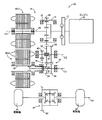
図1は、本発明の一実施例であるハイブリッド車両の駆動装置10(以下、駆動装置10)の構成を説明する骨子図である。駆動装置10は、車両の主駆動力源としてのエンジン12と、そのエンジン12からダンパ装置13を介して伝達された動力を第1電動機MG1および出力部材14に分配する差動機構16を有し、その第1電動機MG1の運転状態が制御されることにより変速比を制御する電気式差動部18と、第1電動機MG1と異なる回転軸心上に配置され副駆動力源として機能する第2電動機MG2と、出力部材14に形成されている出力ギヤ20と噛み合うアイドラギヤ22およびそのアイドラギヤ22と噛み合うドリブンギヤ24から構成される増速機構26と、ドリブンギヤ24が形成されているドリブンギヤ軸28と、第2電動機MG2のロータ軸30に連結されている出力軸32と、出力軸32に形成されている出力ギヤ34およびその出力ギヤ34と噛み合う大径ギヤ36から構成される減速機構38と、大径ギヤ36および小径ギヤ40が形成されているカウンタ軸42と、小径ギヤ40から動力が伝達され、左右の駆動輪44に動力を伝達するデフギヤ46とを、含んで構成されている。なお、第2電動機MG2が本発明の電動機に対応している。
FIG. 1 is a skeleton diagram illustrating the configuration of a hybrid vehicle drive device 10 (hereinafter, drive device 10) according to an embodiment of the present invention. The
この駆動装置10は、FF(フロントエンジン・フロントドライブ)方式のハイブリッド車両に好適に用いられる。また、駆動装置10は4つの回転軸心C1〜C4を有している。具体的には、エンジン12、差動機構16、および第1電動機MG1が配置される第1回転軸心C1、大径ギヤ36および小径ギヤ40が形成されているカウンタ軸42、およびアイドラギヤ22が配置されている回転軸心C2、ドリブンギヤ24が形成されているドリブンギヤ軸28、第2電動機MG2、および出力ギヤ34が形成されている出力軸32が配置されている回転軸心C3、デフギヤ46が配置されている回転軸心C4を有している。このように、エンジン12、第1電動機MG1、および差動機構16と第2電動機M2とが異なる回転軸心上に配置されることで、駆動装置10の軸長が短縮化されている。
This
差動機構16は、エンジン12から出力される動力を第1電動機MG1と出力部材14とに分配する動力分配装置として機能するものであって、第1電動機MG1のロータ軸48に連結されたサンギヤSと、そのサンギヤSと同心に設けられて円筒状の出力部材14の内周部に一体に設けられたリングギヤRと、サンギヤSおよびリングギヤRにそれぞれ噛み合うピニオンギヤPを自転且つ公転可能に支持するキャリヤCAとを備えるシングルピニオン型の遊星歯車装置から構成されている。
The
また、出力部材14に伝達された動力は、出力部材14の外周に形成されている出力ギヤ20と噛み合うアイドラギヤ22を介して第3回転軸心C3に配置されているドリブンギヤ24に伝達される。ドリブンギヤ24が形成されているドリブンギヤ軸28は、ロータ軸30を介して出力軸32に連結されていることから、ドリブンギヤ24に伝達される動力は、ロータ軸30、出力軸32、減速機構38、小径ギヤ40、およびデフギヤ46を介して左右の駆動輪44に伝達される。
The power transmitted to the
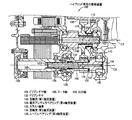
図2は、図1の駆動装置10のうち、第1軸心C1、第2回転軸心C2、および第3回転軸心C3まわりに配置される駆動装置10の構成を同一の平面内に示す断面図である。図2にも示されるように、第1軸心C1まわりにエンジン12、差動機構16、および第1電動機MG1が回転可能に配置され、第2軸心C2まわりにカウンタ軸42が回転可能に配置され、第3回転軸心C3まわりにドリブンギヤ軸28、第2電動機MG2(ロータ軸30)、および出力軸32が回転可能に配置されている。
FIG. 2 shows, in the same plane, the configuration of the
これらの部材は、非回転部材であるケース50内に収容されている。ケース50は、差動機構16、カウンタ軸42、および出力軸32等を収容するギヤ室52と、第1電動機MG1および第2電動機MG2を収容するモータ室54とを、ケース内に形成している。ケース50は、主にギヤ室52を形成する有底筒状の第1ケース50a、ギヤ室52とモータ室54とを仕切る隔壁を含んで構成される筒状の第2ケース50b、および主にモータ室54を形成する第3ケース50cが互いに接続されることで一体的に構成されている。
These members are accommodated in a
エンジン12の動力は、差動機構16を介して第1電動機MG1および出力部材14に分配される。出力部材14は、環状に形成されており、その外周部に出力ギヤ20が形成されている。出力ギヤ20は、第2回転軸心C2まわりに回転可能に配置されているアイドラギヤ22の噛合歯に噛み合わされている。アイドラギヤ22は、カウンタ軸42および大径ギヤ36に形成されている筒部36aの外周側に配置されている。アイドラギヤ22の内周部において、アイドラギヤ22と大径ギヤ36との間を相対回転可能に支持するニードルベアリング56が介挿され、さらに、軸方向においてアイドラギヤ22と小径ギヤ40との間、および、軸方向においてアイドラギヤ22と大径ギヤ36との間にスラスト軸受58がそれぞれ介挿されている。アイドルギヤ22の内周部がこれらのベアリング56、58で支持されることで、カウンタ軸42に対して相対回転可能とされている。
The power of the
アイドラギヤ22の噛合歯がドリブンギヤ24の噛合歯と噛み合わされることで、エンジン12からの動力がアイドラギヤ22を介してドリブンギヤ24に伝達される。ドリブンギヤ24は、第3軸心C3まわりに回転可能なドリブンギヤ軸28の軸方向の一端に形成されている。ドリブンギヤ軸28は、円筒形状を有しており、第2電動機MG2と共通の第3回転軸心C3まわりに回転可能に配置されている。また、ドリブンギヤ軸28の内周側を出力軸32が貫通している。ドリブンギヤ軸28は、軸方向の第2電動機側に配置されるよく知られた複列アンギュラベアリング60によって片持ち状態で回転可能に支持されている。複列アンギュラベアリング60は、第2ケース50bに固定されて支持される、軸方向に並ぶ2個のボールで構成され、実質的に2個の軸受によってドリブンギヤ軸28が支持される。このように、ドリブンギヤ軸28の支持剛性が2個の軸受に相当する複列アンギュラベアリング60によって確保される。なお、複列アンギュラベアリング60が、本発明の第4軸受装置に対応している。
When the meshing teeth of the
ドリブンギヤ軸28には、径方向に突き出す鍔部28aが形成されており、その一端が複列アンギュラベアリング60の内輪と当接させられている。さらに、複列アンギュラベアリング60の鍔部28aと当接する側と反対側からナット62によって締め付けられることで、複列アンギュラベアリング60に軸方向に働くプレロード荷重が負荷される。このプレロード荷重が調整されることで、複列アンギュラベアリング60の支持状態が適宜調整される。ドリブンギヤ軸28の軸方向においてドリブンギヤ24と反対側の端部の内周側には、第2電動機MG2のロータ軸30とスプライン嵌合するための内周歯が形成されている。また、ロータ軸30の軸方向において第1ケース50a側の外周端部には、ドリブンギヤ軸28とスプライン嵌合するための外周歯が形成されており、ドリブンギヤ軸28の内周歯とスプライン嵌合させられている。従って、ドリブンギヤ軸28とロータ軸30とは一体的に回転させられる。すなわち、ドリブンギヤ軸28は、第2電動機MG2のロータ軸30と動力伝達可能に接続されている。
The driven
ロータ軸30は、円筒形状を有しており、第3回転軸心C3まわりに回転可能に支持されている。ロータ軸30は、軸方向において第3ケース50c側の端部が玉軸受66によって回転可能に支持されるとともに、軸方向において第1ケース50a側(第2電動機MG2の出力側)が玉軸受68によって回転可能に支持されている。このように、ロータ軸30は、玉軸受66および玉軸受68によって回転可能に支持されている。また、ロータ軸30の外周部に第2電動機MG2を構成するロータ64が接続されている。従って、第2電動機MG2が駆動(回転)すると、ロータ64とともにロータ軸30が回転させられる。また、ロータ軸30の内周側に形成されている内周歯に、出力軸32の外周端部に形成されている外周歯がスプライン嵌合されることで、ロータ軸30と出力軸32とを動力伝達可能に接続する嵌合部69が形成されている。なお、玉軸受68が本発明の第1軸受装置に対応している。
The
出力軸32は、円筒形状を有しており、第2電動機MG2のロータ軸30と共通の第3回転軸心C3まわりに回転可能に配置されている。また、出力軸32がドリブンギヤ軸28の内周側に配置されており、径方向の一部がドリブンギヤ軸28と重なっている。出力軸32の軸方向において第1ケース50a側は、ドリブンギヤ軸28よりも軸方向に突き出しており、その端部が、玉軸受70によって回転可能に支持されている。また、出力軸32の外周とドリブンギヤ軸28の内周との間に、出力軸32を回転可能に支持するニードルベアリング72が介挿されている。ニードルベアリング72は軸方向において、ドリブンギヤ軸28および複列アンギュラベアリング60と径方向で重なる位置に設けられている。これより、出力軸32の軸方向において玉軸受70と反対側は、ニードルベアリング72によって回転可能に支持されている。具体的には、出力軸32の軸方向の一端が、複列アンギュラベアリング60およびドリブンギヤ軸28を介してニードルベアリング72によって支持されている。また、出力軸32の軸方向において第1ケース50a側の外周には、大径ギヤ36と噛み合う出力ギヤ34が形成されている。この出力ギヤ34は、デフギヤ46等を介して駆動輪44に動力伝達可能に接続されている。また、ドリブンギヤ軸28のドリブンギヤ24が形成される側の軸端と、出力ギヤ34との間には、それらの間の軸方向の荷重を受けるスラスト軸受74が介挿されている。なお、玉軸受70が本発明の第2軸受装置に対応し、ニードルベアリング72が本発明の第3軸受装置に対応している。
The
大径ギヤ36は、第2回転軸心C2まわりに回転可能に支持され、内周端がカウンタ軸42にスプライン嵌合されている。カウンタ軸42は、円筒形状を有しており、軸方向の両端が軸受によって回転可能に支持されている。具体的には、カウンタ軸42の軸方向において第1ケース50a側の端部が円すいころ軸受76によって回転可能に支持されるとともに、軸方向において第3ケース50c側の端部が円すいころ軸受78によって回転可能に支持されている。また、カウンタ軸42の円すいころ軸受76側の端部がナット80によって締め付けられることで、スラスト方向に作用するプレロード荷重が適宜付与される。このように、カウンタ軸42は、円すいころ軸受76および円すいころ軸受78によって支持されている。また、カウンタ軸42の軸方向において円すいころ軸受78側には、小径ギヤ40が形成されており、小径ギヤ40は、図1のデフギヤ46のファイナルドリブンギヤ82(図1参照)に噛み合わされている。
The large-
上記のように構成される駆動装置10の特徴について説明する。ダンパ装置10にあっては、ドリブンギヤ24に伝達されるエンジンの動力が、ドリブンギヤ軸28、ロータ軸30、嵌合部69、および出力軸32の順番で伝達され、さらに、駆動輪44に動力伝達可能に接続されているカウンタ軸42に伝達される。このように、駆動装置10にあっては、エンジン12の動力がドリブンギヤ軸28、ロータ軸30、嵌合部69、および出力軸32の順番で伝達される動力伝達経路が構成され、動力伝達中の振動および騒音を抑制するため、これら動力が伝達される回転軸の支持剛性を高める必要がある。これに対して、ドリブンギヤ軸28は、複列アンギュラベアリング60によって片持ち状態で支持されている。なお、複列アンギュラベアリング60は、2個の軸受から構成されているため、ドリブンギヤ軸28は実質的に2個の軸受によって支持されており、高い支持剛性が確保される。また、ロータ軸30は、玉軸受66および玉軸受68によって回転可能に支持されているので、支持剛性が確保されている。
The characteristics of the
また、出力軸32は、ニードルベアリング72および玉軸受70によって支持されている。なお、ニードルベアリング72は、ドリブンギヤ軸28および複列アンギュラベアリング60を介して出力軸32を支持している。そして、ニードルベアリング72は、径方向においてこれらドリブンギヤ軸28および複列アンギュラベアリング60と重なる位置に配置されるため、ニードルベアリング72が剛性の高いこれらの部材(ドリブンギヤ軸28、複列アンギュラベアリング60)の直下に配置されるので、ニードルベアリング72の支持剛性も確保される。このように、エンジン12から動力が伝達されるドリブンギヤ軸28、ロータ軸30、および出力軸32は、それぞれ各軸受を介して独立して支持されるために支持剛性も高くなることから、エンジン12からこれらの回転軸に動力が伝達されたときに発生する振動や騒音が抑制される。また、出力軸32を支持するニードルベアリング72は、ドリブンギヤ軸28の内周と出力軸32の外周との間に介挿されるので、出力軸32を支持するに際してスペースをとらない。
The
駆動装置10において、ドリブンギヤ軸28がロータ軸30と別体で構成されているため、このドリブンギヤ軸28を支持する複列アンギュラベアリング60が設けられているが、この複列アンギュラベアリング60は径方向において小径ギヤ40と重なる位置に配置されている。小径ギヤ40は、ギヤの径が小さいのでその外周側に空間が形成されやすい。そこで、径方向において小径ギヤ40と重なる位置に複列アンギュラベアリング60が配置されることで空間が有効に利用され、複列アンギュラベアリング60を設けることによる装置の大型化が防止される。
In the
駆動装置10において、動力を伝達する各噛合歯車は、何れも斜歯に形成されており、動力が伝達される際には、スラスト荷重が発生する。また、エンジン側から動力が伝達される場合と、駆動輪44側から動力が伝達される場合とでは、スラスト荷重の向きが反転する。ここで、ドリブンギヤ軸28を支持する複列アンギュラベアリング60によって左右のスラスト荷重を受け持たせることもできるが、複列アンギュラベアリング60の軸方向の移動が阻止されるように、複列アンギュラベアリング60の外輪をケースに圧入する、或いは、その外輪の軸方向の移動を阻止するスナップリングを新たに設定するなど製造工数が増加する。さらに、左右のスラスト荷重を保持するよう設計することで、軸受が大型化する。出力軸32を支持する玉軸受70についても同様に、左右のスラスト荷重を受け持たせる場合、製造工数の増加および軸受の大型化が発生する。
In the driving
これに対して、ドリブンギヤ軸28および出力軸32の間には、スラスト軸受74が介挿されており、互いの回転軸で発生するスラスト荷重がスラスト軸受74を介して伝達されるように構成されている。さらに、複列アンギュラベアリング60および玉軸受70が、スラスト荷重をその力の向きに応じて分担するように構成されている。例えば、動力伝達中にドリブンギヤ軸28および出力軸32に玉軸受70側(図において右側)に働くスラスト荷重が発生すると、ドリブンギヤ軸28のスラスト荷重もスラスト軸受74を介して出力軸32に伝達され、これらドリブンギヤ軸28および出力軸32のスラスト荷重が、玉軸受70によって受け持つように設定されている。一方、ドリブンギヤ軸28および出力軸32に複列アンギュラベアリング60側(図において左側)に働くスラスト荷重が発生すると、出力軸32のスラスト荷重もスラスト軸受74を介してドリブンギヤ軸28に伝達され、これらドリブンギヤ軸28および出力軸32のスラスト荷重が、複列アンギュラベアリング60によって受け持つように設定されている。これより、ドリブンギヤ軸28および出力軸32で発生するスラスト荷重は、複列アンギュラベアリング60および玉軸受70によってそれぞれ分担され、複列アンギュラベアリング60および玉軸受70に軸方向の一方のみに作用するスラスト荷重を受け持たせる設計とすることで、複列アンギュラベアリング60および玉軸受70の大型化も防止される。また、複列アンギュラベアリング60および玉軸受70は、いずれもケース50に圧入することもなく、軸方向の移動を規制するスナップリングを設ける必要もないので、製造工数の増加も防止される。なお、ドリブンギヤ軸28と複列アンギュラベアリング60とを、予め別の組付ラインで組み付けておくことで、主製造ラインの工数増加も抑制される。
On the other hand, a
上述のように、本実施例によれば、出力軸32は、ドリブンギヤ軸28よりも軸方向に突き出す部位が玉軸受70によって回転可能に支持されるとともに、出力軸32の外周とドリブンギヤ軸28の内周に介挿されているニードルベアリング72によって回転可能に支持される。このように、出力軸32が玉軸受70およびニードルベアリング72によって支持されるため、出力軸32の支持剛性が高くなり、動力伝達中の振動および騒音を抑制することができる。また、ニードルベアリング72は、ドリブンギヤ軸28の内周と、出力軸32の外周との間に介挿されるため、ニードルベアリング72を設けたことでスペースを取ることもなく駆動装置10の大型化も抑制される。
As described above, according to this embodiment, the
また、本実施例によれば、ドリブンギヤ軸28が2個の軸受で構成される複列アンギュラベアリング60によって片持ち状態で回転可能に支持されることで、ドリブンギヤ軸28についても高い支持剛性を確保することができる。また、複列アンギュラベアリング60は、非回転部材である第2ケース50b(ケース50)に固定されて支持されるので支持剛性が高い。
Further, according to this embodiment, the driven
また、本実施例によれば、ニードルベアリング72が径方向において複列アンギュラベアリング60と重なる位置に配置されることで、複列アンギュラベアリング60の近傍にニードルベアリング72が配置され、ニードルベアリング72の支持剛性がさらに高くなり、動力伝達中の振動および騒音を一層抑制することができる。
Further, according to the present embodiment, the needle bearing 72 is disposed in a position overlapping the double-row
また、本実施例によれば、ドリブンギヤ軸28と出力軸32との間でスラスト軸受74を介してスラスト荷重が伝達されるので、ドリブンギヤ軸28を支持する複列アンギュラベアリング60と出力軸32を支持する玉軸受70とでスラスト荷重を分担させることができる。そして、複列アンギュラベアリング60および玉軸受70を、それぞれ軸方向の一方に働くスラスト荷重を受け持つ構造とすることができ、複列アンギュラベアリング60および玉軸受70が軸方向の両方に働くスラスト荷重を受け持つ場合と比べて複列アンギュラベアリング60および玉軸受70を小型化することができる。
Further, according to this embodiment, since the thrust load is transmitted between the driven
つぎに、本発明の他の実施例を説明する。なお、以下の説明において前述の実施例と共通する部分には同一の符号を付して説明を省略する。 Next, another embodiment of the present invention will be described. In the following description, parts common to those in the above-described embodiment are denoted by the same reference numerals and description thereof is omitted.
図3は、本発明の他の実施例であるハイブリッド車両の駆動装置100(駆動装置100)の断面図であり、前述の実施例の図2に対応している。図3の駆動装置100を前述した駆動装置10と比較すると、第1回転軸心C1まわりの構成は基本的には同様であり、第2回転軸心C2および第3回転軸心C3まわりの構成が異なっている。本実施例では、第1回転軸心C1まわりの構成については図面およびその説明を省略し、第2回転軸心C2および第3回転軸心C3まわりの構成を中心に説明する。
FIG. 3 is a cross-sectional view of a hybrid vehicle drive device 100 (drive device 100) according to another embodiment of the present invention, and corresponds to FIG. 2 of the above-described embodiment. 3 is compared with the driving
駆動装置100においても、第1回転軸心C1まわりにエンジン12、差動機構16、および第1電動機MG1が配置され(図示せず)、第2回転軸心C2まわりにカウンタ軸102が回転可能に配置され、第3回転軸心C3まわりにドリブンギヤ軸104、第2電動機MG2(ロータ軸105)、および出力軸106が回転可能に配置されている。なお、駆動装置100にあっては、ドリブンギヤ軸104が出力軸106の内周側に配置されている。
Also in the
エンジン12から動力が伝達される出力部材108の出力ギヤ110が、第2回転軸心C2まわりに回転可能に配置されているアイドラギヤ112の噛合歯と噛み合わされている。アイドラギヤ112は、カウンタ軸102および大径ギヤ114に形成されている筒部116の外周側に配置されている。アイドラギヤ112の内周部には、アイドラギヤ114とカウンタ軸102との間を相対回転可能に支持するニードルベアリング118が介挿され、さらに、軸方向の両端にスラスト軸受120が介挿されている。アイドルギヤ112の内周部がこれらの軸受で支持されることで、カウンタ軸102に対して相対回転可能とされている。
An
アイドラギヤ112の噛合歯が、第3回転軸心C3まわりに配置されているドリブンギヤ122の噛合歯と噛み合わされている。従って、出力ギヤ110およびアイドラギヤ112を介して、ドリブンギヤ122にエンジン12からの動力が伝達される。ドリブンギヤ122は、第3回転軸心C3まわりに配置されているドリブンギヤ軸104の軸方向の一端側(第1ケース50a側)に形成されている。また、ドリブンギヤ軸104は、ロータ軸105および出力軸106の内周側に配置されている。なお、ドリブンギヤ軸104の支持機構については後述するものとする。ドリブンギヤ軸104の軸方向の他端側(第3ケース50c側)には、ロータ軸105とスプライン嵌合するための外周歯が形成されている。このドリブンギヤ軸104の外周歯に、ロータ軸105の内周側に形成されている内周歯がスプライン嵌合されることで、ドリブンギヤ軸104とロータ軸105と動力伝達可能に接続する嵌合部123が形成されている。
The meshing teeth of the
ロータ軸105は、円筒形状を有しており、第3回転軸心C3まわりに回転可能に配置されている。ロータ軸105は、軸方向において第3ケース50c側の端部が玉軸受124によって回転可能に支持されるとともに、軸方向において第1ケース50a側(電動機の出力側)が玉軸受126によって回転可能に支持されている。このように、ロータ軸105は、玉軸受124および玉軸受126によって回転可能に支持されている。また、ロータ軸105の外周部に第2電動機MG2を構成するロータ64が接続されている。従って、第2電動機MG2が駆動(回転)すると、ロータ64とともにロータ軸105が回転させられる。また、ロータ軸105の軸方向において第1ケース50a側の外周端部に、出力軸106とスプライン嵌合するための外周歯が形成されている。なお、玉軸受126が本発明の第1軸受装置に対応している。
The
ロータ軸105に形成されている外周歯が、円筒形状を有する出力軸106の軸方向の一端側(第3ケース50c側)に形成されている内周歯とスプライン嵌合されることで、ロータ軸105と出力軸106とが動力伝達可能に接続されている。出力軸106は、第3回転軸C3まわりに回転可能に支持されており、ドリブンギヤ軸104の外周側に配置されることで、径方向においてドリブンギヤ軸104と重なっている。出力軸106は、複列アンギュラベアリング128によって回転可能に片持ち状態で支持されている。複列アンギュラベアリング128は、第2ケース50bに固定されて支持される、軸方向に並んだ2個のボールで構成されており、出力軸106が実質的に2個の軸受によって支持されることで出力軸106の支持剛性が確保される。なお、複列アンギュラベアリング128が本発明の第4軸受装置に対応している。
The outer peripheral teeth formed on the
また、出力軸106の軸方向において第2電動機MG2側と反対側の外周部に、出力ギヤ134が形成されている。この出力ギヤ134とドリブンギヤ122との間にスラスト軸受135が介挿されており、ドリブンギヤ軸104および出力軸106間で発生するスラスト荷重がスラスト軸受135を介して他方の回転軸に伝達される。また、後述する玉軸受136および複列アンギュラベアリング128は、前述の実施例と同様に、軸方向の一方に作用するスラスト荷重のみ受け持つことができるよう構成されている。
Further, an
次に、ドリブンギヤ軸104の支持機構について説明する。ドリブンギヤ軸104は、第3回転軸心C3まわりに回転可能に支持されている。ドリブンギヤ軸104の軸方向において第1ケース50a側が、出力軸106よりも軸方向に突き出しており、その外周端部が玉軸受136によって支持されている。また、ドリブンギヤ軸104の外周と出力軸106の内周との間に、ドリブンギヤ軸104を回転可能に支持するニードルベアリング138が介挿されており、ドリブンギヤ軸104は、複列アンギュラベアリング128および出力軸106を介してこのニードルベアリング138によって支持されている。ニードルベアリング138は、径方向において出力軸106および複列アンギュラベアリング128と重複する位置に設けられている。ここで、複列アンギュラベアリング128および出力軸106は剛性が高いので、その直下に配置されているニードルベアリング138の支持剛性も高くなる。なお、玉軸受136が本発明の第2軸受装置に対応し、ニードルベアリング138が本発明の第3軸受装置に対応している。
Next, a support mechanism for the driven
本実施例の駆動装置100においても前述した実施例の駆動装置10と同様の効果が得られる。例えば、駆動装置100において、ドリブンギヤ軸104とロータ軸105とがスプライン嵌合で接続されるとともに、ロータ軸105と出力軸106とがスプライン嵌合で接続されており、動力伝達中の振動および騒音を抑制するため、各回転軸の支持剛性を高める必要がある。これに対して、ドリブンギヤ軸104は、玉軸受136およびニードルベアリング138によって支持され、ロータ軸105は、玉軸受124および玉軸受126によって支持され、出力軸106は、2個軸受から構成される複列アンギュラベアリング128によって支持されている。このように、エンジン12からの動力が伝達される各回転軸がそれぞれ独立して支持されることで、各回転軸とも高い支持剛性が得られるため、動力伝達中の振動や騒音が抑制される。また、ドリブンギヤ軸104を支持するニードルベアリング138は、ドリブンギヤ軸104の外周と出力軸106の内周との間に介挿されるので、ドリブンギヤ軸104を支持するに際して大きなスペースを必要としない。
Also in the
また、本実施例の駆動装置100にあっては、出力軸106がドリブンギヤ軸104の外周側に配置されるので、前述した出力軸32がドリブンギヤ軸28の内周側に配置される駆動装置10と比べて出力軸106の軸径を大きくすることが容易となる。従って、出力軸106の軸強度が確保しやすくなるので、大トルクが伝達される車両に適している。なお、前述した実施例の駆動装置10にあっては、ドリブンギヤ軸28が出力軸32の外周側に配置されるので、アイドラギヤ22と噛み合うドリブンギヤ24が出力ギヤ34よりも軸方向において第2電動機MG2側に配置される。ここで、アイドラギヤ22は、第1回転軸C1まわりに回転可能に配置される出力部材14の出力ギヤ20とも噛み合うことから、出力ギヤ20が出力部材14の軸方向において中央ないし中央近傍に配置されている(図2参照)。従って、駆動装置100のように、出力部材108を軸方向に長くして出力ギヤ110を軸方向の端部に配置する必要もなくなることから、駆動装置10にあっては出力部材14の軸方向の長さが短くなる。このように、出力部材14が軸方向に短くなるため、駆動装置10をコンパクトに構成することができる。
Further, in the
また、ロータ軸105と出力軸106とが別体で構成されているため、この出力軸106を支持する複列アンギュラベアリング128が設けられているが、この複列アンギュラベアリング128がカウンタ軸102に形成されている小径ギヤ146と径方向に重なる位置に配置されることで、小径ギヤ146の外周側に形成される空間に複列アンギュラベアリング128が配置され、複列アンギュラベアリング128を設けたことによる装置の大型化が防止される。
Further, since the
また、ドリブンギヤ軸104および出力軸106の間で発生するスラスト荷重がスラスト軸受135を介して伝達され、そのスラスト荷重を玉軸受136と複列アンギュラベアリング128とで分担する構造とすることで、軸受の大型化が抑制される。また、軸受の軸方向への移動を阻止する構造とする必要もないので製造工数の増加も抑制される。
In addition, the thrust load generated between the driven
上述のように、本実施例によれば、内周側に配置されるドリブンギヤ軸104は、嵌合部123を介してロータ軸105に接続される。ここで、そのドリブンギヤ軸104は、出力軸106よりも軸方向に突き出す部位が玉軸受136によって支持されるとともに、出力軸106の内周とドリブンギヤ軸104の外周との間に介挿されるニードルベアリング138によって支持される。従って、ドリブンギヤ軸104が、ニードルベアリング138および玉軸受136によって支持されるためにその支持剛性が高くなり、動力伝達中の振動および騒音を抑制することができる。また、ニードルベアリング138は、出力軸106の内周とドリブンギヤ軸104の外周との間に介挿されるので、スペースを取ることもなく駆動装置100の大型化も抑制される。
As described above, according to this embodiment, the driven
また、本実施例によれば、出力軸106についても、2個の軸受から構成される複列アンギュラベアリング128によって支持されることで高い支持剛性が得られる。このように、ドリブンギヤ軸104および出力軸106ともに支持剛性が高くなるため、動力伝達中の振動および騒音が抑制される。
Further, according to this embodiment, the
図4は、本発明のさらに他の実施例であるハイブリッド車両の駆動装置160(駆動装置160)の断面図であり、前述の実施例の図2、図3に対応している。図4の駆動装置160を前述した駆動装置10と比較すると、複列アンギュラベアリングを支持する部材が別体で構成されている点で相違し、他の構成は駆動装置10と基本的に変わらない。以下、駆動装置10と相違する複列アンギュラベアリングの支持機構について説明する。
FIG. 4 is a cross-sectional view of a hybrid vehicle drive device 160 (drive device 160) according to still another embodiment of the present invention, and corresponds to FIGS. 2 and 3 of the above-described embodiment. 4 is different from the
駆動装置160においても、アイドラギヤ22から動力が伝達されるドリブンギヤ162が形成されているドリブンギヤ軸164が第3回転軸心C3まわりに回転可能に支持されている。ドリブンギヤ軸164は、2個の軸受で構成される複列アンギュラベアリング166によって片持ち状態で支持されている。なお、複列アンギュラベアリング166が本発明の第4軸受装置に対応している。
Also in the driving device 160, a driven
ここで、複列アンギュラベアリング166は、ケース50(第2ケース50b)に固定されたリテーナ168によって支持されている。リテーナ168は、円筒状に形成されており、外周部にはリテーナ168をボルト170でケース50に固定するために径方向に突き出すフランジ部172が周方向に複数箇所形成されている。また、複列アンギュラベアリング166を保持するための円筒形状の筒部173が形成されている。図5は、ケース50(第2ケース50b)にリテーナ168が嵌め付けられた状態を示している。図5において斜線が施されている部位がリテーナ168に対応している。図5に示すように、フランジ部172が周方向に4箇所形成されており、各フランジ部172にボルト締結用のボルト穴が形成されている。
Here, the double row
また、リテーナ168の軸方向においてケース50に接続される側の内周部には、ケース50に形成されている環状穴174に嵌合される円還状のボス176が形成されている。このボス176が形成されることで、リテーナ168の外周側にも段付部が形成される。このボス176の段付部とケース50の環状穴176によって形成される段付部とが嵌め合わされた状態でボルト170が締結されることで、リテーナ168がケース50に固定される。このボス176および環状穴176の段付部とが嵌め合わされることでリテーナ168の芯出し精度も高く、ノックピン等も不要となる。また、リテーナ168が例えば鋳鉄等で形成されることで、アルミニウム合金で形成される場合に比べて支持剛性が高められる。
Further, a return-shaped
また、リテーナ168がケース50に対して別体で構成されるため、鋳造による制限もなくリテーナ168の筒部173の軸方向の長さを長くすることができる。リテーナ168の筒部173が軸方向に長くなると、ドリブンギヤ軸164のドリブンギヤ162と複列アンギュラベアリング166との間の軸方向の距離を短くすることができる。本実施例でも、図5の複列アンギュラベアリング166は、図2の複列アンギュラベアリング60と比較しても、ドリブンギヤ162との軸方向の距離が短くなっている。このように、複列アンギュラベアリング166とドリブンギヤ162との軸方向の距離が短くなると、複列アンギュラベアリング166にかかる軸受荷重が低減される。従って、複列アンギュラベアリング166を小型化することも可能となる。
In addition, since the
なお、前述した図2に示すケース50と複列アンギュラベアリング60の支持部とが一体となった構造では、その支持部の軸方向の長さを長くすることに限界がある。これは、ラインでの組付工程の際に前記支持部が干渉しないよう、支持部がケースの合わせ面よりも突き出さない程度の長さに制限されるためである。これに対して、駆動装置160の組付の際には、まず、モータ室側から組み付けられ、次いでギヤ室側が組み付けられるが、リテーナ168が、ギヤ室側の組付直前にケース50に組み付けられることで、上述した寸法の制限もなくリテーナ168の筒部173を軸方向に長くすることができる。
In the structure in which the
上述のように、本実施例によっても前述した実施例と略同様の効果を得ることができ、特に、複列アンギュラベアリング166が、非回転部材であるケース50に固定されている別体のリテーナ168を介して支持されることで以下の効果を得ることができる。例えばリテーナ168を鋳鉄で製造することで、複列アンギュラベアリング166を支持する支持剛性を一層高めることができる。また、リテーナ168の筒部173を軸方向に長くすることもできるので、複列アンギュラベアリング166とドリブンギヤ162との軸方向の距離を短くすることができる。これより、複列アンギュラベアリング166にかかる荷重が低減され、結果として複列アンギュラベアリング166を小型化することができる。
As described above, the present embodiment can achieve substantially the same effect as the above-described embodiment, and in particular, a separate retainer in which the double-row
図6は、本発明のさらに他の実施例であるハイブリッド車両の駆動装置180(駆動装置180)の断面図である。駆動装置180を前述した図2に示す駆動装置10と比較すると、ドリブンギヤ軸とロータ軸とが一体成形されている点で相違している。以下、駆動装置10と相違する、第3回転軸心C3まわりの支持構造について説明する。
FIG. 6 is a cross-sectional view of a drive device 180 (drive device 180) for a hybrid vehicle that is still another embodiment of the present invention. The driving device 180 is different from the driving
第3回転軸心C3まわりには、アイドラギヤ22と噛み合うドリブンギヤ182が形成されている動力伝達軸184が第3回転軸心C3まわりに回転可能に配置されている。動力伝達軸184は円筒形状を有しており、その内周側に出力軸185が第3回転軸心C3まわりに回転可能に配置されている。
A
動力伝達軸184は、前述した実施例のドリブンギヤ軸および第2電動機MG2のロータ軸とが一体成形されて構成される回転軸である。動力伝達軸184は、軸方向において第3ケース50c側の端部が玉軸受186によって回転可能に支持されており、さらに、軸方向において中間程度の位置(径方向において第2ケース50bと重なる位置)に配置されている玉軸受188によって回転可能に支持されている。動力伝達軸184は、これら玉軸受186、188によって支持されることで支持剛性が確保される。なお、玉軸受188が本発明の第1軸受装置に対応している。
The
出力軸185は、動力伝達軸184の内周側に配置されており、軸方向の第3ケース50c側の一端が動力伝達軸184の内周部とスプライン嵌合されることで、動力伝達軸184と出力軸185とを動力伝達可能に接続する嵌合部189が形成されている。また、出力軸185の軸方向において第1ケース50a側の外周部に出力ギヤ190が形成されている。出力軸185の軸方向において第1ケース50a側の外周端部が玉軸受192によって回転可能に支持されている。また、出力軸185の外周と動力伝達軸184の内周との間には、出力軸185を回転可能に支持するニードルベアリング194が介挿されている。出力軸185は、これら玉軸受192およびニードルベアリング194によって回転可能に支持される。このように動力伝達軸184および出力軸185が、それぞれ独立して支持されてることで各回転軸の支持剛性が高くなり、動力伝達中の振動および騒音が抑制される。なお、玉軸受192が本発明の第2軸受装置に対応し、ニードルベアリング194が第3軸受装置に対応している。
The
また、ニードルベアリング194は軸方向において、動力伝達軸184を支持する玉軸受188と径方向に重なる位置に配置されている。このように、玉軸受188とニードルベアリング194とが径方向に重なることで、ニードルベアリング194の支持剛性も高くなり、動力伝達中の振動および騒音が一層抑制される。
Further, the needle bearing 194 is arranged in a position overlapping with the
上述のように、本実施例によれば、ロータ軸とドリブンギヤ軸とが一体成形された動力伝達軸184を用いることで、ロータ軸とドリブンギヤ軸とが別体の場合に設けられていた複列アンギュラベアリングを省略することができる。
As described above, according to this embodiment, by using the
以上、本発明の実施例を図面に基づいて詳細に説明したが、本発明はその他の態様においても適用される。 As mentioned above, although the Example of this invention was described in detail based on drawing, this invention is applied also in another aspect.
例えば、前述の実施例の駆動装置10では、ニードルベアリング72が複列アンギュラベアリング60と径方向で重なる位置に配置されているが、ニードルベアリング72を玉軸受68と径方向で重なる位置に配置しても構わない。また、駆動装置100では、ニードルベアリング138が複列アンギュラベアリング128と径方向で重なる位置に配置されているが、ニードルベアリング138を玉軸受126と径方向で重なる位置に配置しても構わない。また、上記径方向への重なりは、軸受の一部が重なるものであっても構わない。
For example, in the driving
また、前述の実施例の駆動装置180では、ロータ軸とドリブンギヤ軸とが一体成形された動力伝達軸184が採用されているが、ロータ軸と出力軸とが一体成形され、その回転軸の内周側にドリブンギヤ軸が配置され、ドリブンギヤ軸とその回転軸とが嵌合される構成であっても構わない。
In the driving device 180 of the above-described embodiment, the
また、前述の実施例の駆動装置100においても、別体で形成されているリテーナによって複列アンギュラベアリング128が支持される構造としても構わない。
Also in the
また、前述の実施例の駆動装置10、100、160、180は、フロントエンジ・フロントドライブ方式(FF方式)の駆動装置であったが、例えばRR方式など他の方式の駆動装置においても適宜適用することができる。
In addition, the driving
なお、上述したのはあくまでも一実施形態であり、本発明は当業者の知識に基づいて種々の変更、改良を加えた態様で実施することができる。 The above description is only an embodiment, and the present invention can be implemented in variously modified and improved forms based on the knowledge of those skilled in the art.
10、100、160、180:ハイブリッド車両の駆動装置
12:エンジン
24、122、162、182:ドリブンギヤ
28、104、164:ドリブンギヤ軸
30、105:ロータ軸
32、106、185:出力軸
44:駆動輪
50:ケース
60、128、166:複列アンギュラベアリング(第4軸受装置)
68、126、188:玉軸受(第1軸受装置)
69、123:嵌合部
70、136、192:玉軸受(第2軸受装置)
72、138、194:ニードルベアリング(第3軸受装置)
74、135:スラスト軸受
168:リテーナ
184:動力伝達軸(一体成形されたロータ軸とドリブンギヤ軸)
MG2:第2電動機(電動機)
10, 100, 160, 180: Drive device for hybrid vehicle 12:
68, 126, 188: Ball bearing (first bearing device)
69, 123: Fitting
72, 138, 194: Needle bearing (third bearing device)
74, 135: Thrust bearing 168: Retainer 184: Power transmission shaft (integrated rotor shaft and driven gear shaft)
MG2: Second electric motor (electric motor)
Claims (10)
前記電動機のロータ軸と共通の回転軸心まわりに回転可能に配置され、該電動機のロータ軸と動力伝達可能に接続され、且つ、前記エンジンからの動力が伝達されるドリブンギヤが形成されているドリブンギヤ軸と、
前記電動機のロータ軸と共通の回転軸心まわりに回転可能に配置されるとともに、少なくとも一部が前記ドリブンギヤ軸と径方向において重なる位置に配置され、且つ、前記ロータ軸と動力伝達可能に接続されるとともに、駆動輪に動力伝達可能に接続されている出力軸と、
前記電動機のロータ軸を出力側で回転可能に支持する第1軸受装置と、
前記ドリブンギヤ軸および前記出力軸のうち内周側に配置される一方の回転軸を回転可能に支持する第2軸受装置と、
前記ドリブンギヤ軸および前記出力軸のうち内周側に配置される一方の回転軸の外周と前記ロータ軸の内周または前記ドリブンギヤ軸および前記出力軸のうち外周側に配置される他方の回転軸の内周との間に介挿されて、該一方の回転軸を回転可能に支持する第3軸受装置と、
を含むことを特徴とするハイブリッド車両の駆動装置。 A drive device for a hybrid vehicle in which an engine and an electric motor are arranged on different rotation axes,
A driven gear, which is rotatably arranged around a rotation axis common to the rotor shaft of the electric motor, is connected to the rotor shaft of the electric motor so as to be able to transmit power, and has a driven gear to which power from the engine is transmitted. The axis,
The motor is arranged so as to be rotatable around a rotation axis common to the rotor shaft of the electric motor, and at least a part thereof is arranged at a position overlapping with the driven gear shaft in the radial direction, and is connected to the rotor shaft so as to transmit power. And an output shaft connected to the drive wheel so that power can be transmitted,
A first bearing device that rotatably supports the rotor shaft of the electric motor on the output side;
A second bearing device rotatably supporting one of the driven gear shaft and the output shaft disposed on the inner peripheral side;
Of the driven gear shaft and the output shaft, the outer periphery of one rotating shaft disposed on the inner peripheral side and the inner periphery of the rotor shaft or the other rotating shaft disposed on the outer peripheral side of the driven gear shaft and the output shaft. A third bearing device interposed between the inner periphery and rotatably supporting the one rotating shaft;
A drive device for a hybrid vehicle, comprising:
前記出力軸は、前記ロータ軸と嵌合されることで該ロータ軸と動力伝達可能に接続され、
前記出力軸は、前記第2軸受装置によって支持され、
前記出力軸の外周と前記ドリブンギヤ軸の内周との間に前記第3軸受装置が介挿され、
前記ドリブンギヤ軸は、軸方向の前記電動機側において少なくとも2個の軸受から成る前記第4軸受装置によって片持ち状態で回転可能に支持されていることを特徴とする請求項3のハイブリッド車両の駆動装置。 The driven gear shaft is disposed on the outer peripheral side of the output shaft,
The output shaft is connected to the rotor shaft so as to be able to transmit power by being fitted to the rotor shaft,
The output shaft is supported by the second bearing device,
The third bearing device is interposed between the outer periphery of the output shaft and the inner periphery of the driven gear shaft,
4. The drive apparatus for a hybrid vehicle according to claim 3 , wherein the driven gear shaft is rotatably supported in a cantilevered state by the fourth bearing device comprising at least two bearings on the motor side in the axial direction. .
前記ドリブンギヤ軸は、前記ロータ軸と嵌合されることで該ロータ軸と動力伝達可能に接続され、
前記ドリブンギヤ軸は、前記第2軸受装置によって支持され、
前記ドリブンギヤ軸の外周と前記出力軸の内周との間に前記第3軸受装置が介挿され、
前記出力軸は、軸方向の前記電動機側において少なくとも2個の軸受から成る前記第4軸受装置によって片持ち状態で回転可能に支持されていることを特徴とする請求項3のハイブリッド車両の駆動装置。 The driven gear shaft is disposed on the inner peripheral side of the output shaft,
The driven gear shaft is connected to the rotor shaft so as to be able to transmit power by being fitted to the rotor shaft,
The driven gear shaft is supported by the second bearing device,
The third bearing device is interposed between the outer periphery of the driven gear shaft and the inner periphery of the output shaft;
4. The hybrid vehicle drive device according to claim 3 , wherein the output shaft is rotatably supported in a cantilevered state by the fourth bearing device comprising at least two bearings on the motor side in the axial direction. .
前記出力軸は、前記ロータ軸と嵌合されることで該ロータ軸と動力伝達可能に接続され、
前記ロータ軸と前記ドリブンギヤ軸とが一体形成されていることを特徴とする請求項1のハイブリッド車両の駆動装置。 The driven gear shaft is disposed on the outer peripheral side of the output shaft,
The output shaft is connected to the rotor shaft so as to be able to transmit power by being fitted to the rotor shaft,
2. The drive apparatus for a hybrid vehicle according to claim 1, wherein the rotor shaft and the driven gear shaft are integrally formed.
Priority Applications (5)
| Application Number | Priority Date | Filing Date | Title |
|---|---|---|---|
| JP2013269178A JP6160478B2 (en) | 2013-12-26 | 2013-12-26 | Drive device for hybrid vehicle |
| DE112014006026.7T DE112014006026B4 (en) | 2013-12-26 | 2014-12-22 | Driving device for a hybrid vehicle |
| CN201480070415.4A CN105848945B (en) | 2013-12-26 | 2014-12-22 | For the driving device of hybrid vehicle |
| PCT/IB2014/002856 WO2015097529A1 (en) | 2013-12-26 | 2014-12-22 | Drive device for hybrid vehicle |
| US15/105,202 US9731590B2 (en) | 2013-12-26 | 2014-12-22 | Drive device for hybrid vehicle |
Applications Claiming Priority (1)
| Application Number | Priority Date | Filing Date | Title |
|---|---|---|---|
| JP2013269178A JP6160478B2 (en) | 2013-12-26 | 2013-12-26 | Drive device for hybrid vehicle |
Publications (2)
| Publication Number | Publication Date |
|---|---|
| JP2015123844A JP2015123844A (en) | 2015-07-06 |
| JP6160478B2 true JP6160478B2 (en) | 2017-07-12 |
Family
ID=52444325
Family Applications (1)
| Application Number | Title | Priority Date | Filing Date |
|---|---|---|---|
| JP2013269178A Active JP6160478B2 (en) | 2013-12-26 | 2013-12-26 | Drive device for hybrid vehicle |
Country Status (5)
| Country | Link |
|---|---|
| US (1) | US9731590B2 (en) |
| JP (1) | JP6160478B2 (en) |
| CN (1) | CN105848945B (en) |
| DE (1) | DE112014006026B4 (en) |
| WO (1) | WO2015097529A1 (en) |
Families Citing this family (6)
| Publication number | Priority date | Publication date | Assignee | Title |
|---|---|---|---|---|
| JP6156135B2 (en) * | 2013-12-26 | 2017-07-05 | トヨタ自動車株式会社 | Drive device for hybrid vehicle |
| JP6160478B2 (en) * | 2013-12-26 | 2017-07-12 | トヨタ自動車株式会社 | Drive device for hybrid vehicle |
| US10035414B1 (en) * | 2017-01-18 | 2018-07-31 | GM Global Technology Operations LLC | Automatically-shiftable hybrid transaxle |
| JP6957930B2 (en) * | 2017-03-29 | 2021-11-02 | 三菱自動車工業株式会社 | Ground structure of drive unit for electric vehicle |
| US10781909B2 (en) * | 2017-06-30 | 2020-09-22 | Tesla, Inc. | Windage tray for advanced lubrication and enhanced performance |
| JP7011636B2 (en) * | 2019-10-11 | 2022-01-26 | 本田技研工業株式会社 | Drive |
Family Cites Families (16)
| Publication number | Priority date | Publication date | Assignee | Title |
|---|---|---|---|---|
| US3986413A (en) * | 1975-07-03 | 1976-10-19 | Ford Motor Company | Four-speed automatic coupling transmission |
| JPS59164439A (en) * | 1983-03-10 | 1984-09-17 | Honda Motor Co Ltd | Parallel shaft type gear transmission for vehicles |
| JP2857911B2 (en) * | 1990-03-29 | 1999-02-17 | スズキ株式会社 | Power unit |
| JP4244055B2 (en) | 1999-12-27 | 2009-03-25 | アイシン・エィ・ダブリュ株式会社 | Hybrid drive device |
| JP3909644B2 (en) | 1999-12-27 | 2007-04-25 | アイシン・エィ・ダブリュ株式会社 | Hybrid drive device |
| US7086977B2 (en) * | 2001-05-03 | 2006-08-08 | Ford Global Technologies, Llc | Transmission arrangements for hybrid electric vehicles |
| JP5413633B2 (en) * | 2007-10-19 | 2014-02-12 | アイシン・エィ・ダブリュ株式会社 | Hybrid drive device |
| JP2011183946A (en) * | 2010-03-09 | 2011-09-22 | Aisin Aw Co Ltd | Hybrid driving device |
| JP5454393B2 (en) * | 2010-07-07 | 2014-03-26 | トヨタ自動車株式会社 | Hybrid drive device for vehicle |
| JP2012122595A (en) * | 2010-12-10 | 2012-06-28 | Toyota Motor Corp | Structure for supporting coupling shaft, and hybrid drive system with the same |
| JP5331169B2 (en) | 2011-07-19 | 2013-10-30 | トヨタ自動車株式会社 | Hybrid vehicle drive device |
| WO2013128586A1 (en) * | 2012-02-28 | 2013-09-06 | トヨタ自動車株式会社 | Drive device for hybrid vehicle |
| JP2014101931A (en) | 2012-11-20 | 2014-06-05 | Nissan Motor Co Ltd | Control device of automatic transmission |
| JP6156135B2 (en) | 2013-12-26 | 2017-07-05 | トヨタ自動車株式会社 | Drive device for hybrid vehicle |
| JP6160478B2 (en) * | 2013-12-26 | 2017-07-12 | トヨタ自動車株式会社 | Drive device for hybrid vehicle |
| JP6222164B2 (en) * | 2015-04-27 | 2017-11-01 | トヨタ自動車株式会社 | Vehicle power transmission structure |
-
2013
- 2013-12-26 JP JP2013269178A patent/JP6160478B2/en active Active
-
2014
- 2014-12-22 DE DE112014006026.7T patent/DE112014006026B4/en active Active
- 2014-12-22 US US15/105,202 patent/US9731590B2/en active Active
- 2014-12-22 WO PCT/IB2014/002856 patent/WO2015097529A1/en active Application Filing
- 2014-12-22 CN CN201480070415.4A patent/CN105848945B/en not_active Expired - Fee Related
Also Published As
| Publication number | Publication date |
|---|---|
| CN105848945A (en) | 2016-08-10 |
| US20160311306A1 (en) | 2016-10-27 |
| JP2015123844A (en) | 2015-07-06 |
| CN105848945B (en) | 2018-06-22 |
| DE112014006026T5 (en) | 2016-09-22 |
| WO2015097529A1 (en) | 2015-07-02 |
| US9731590B2 (en) | 2017-08-15 |
| DE112014006026B4 (en) | 2023-03-23 |
Similar Documents
| Publication | Publication Date | Title |
|---|---|---|
| JP6160478B2 (en) | Drive device for hybrid vehicle | |
| JP5664663B2 (en) | Power transmission device for vehicle | |
| JP5331169B2 (en) | Hybrid vehicle drive device | |
| US10112472B2 (en) | Drive device for hybrid vehicle | |
| JP6327396B2 (en) | Planetary gear mechanism | |
| US10989297B2 (en) | Electric powertrain with sun bearing | |
| US10807467B2 (en) | Epicyclic gearbox | |
| JP4320668B2 (en) | Power transmission device for vehicle | |
| JP5528490B2 (en) | Vehicle drive device | |
| US11241947B2 (en) | Vehicle driving device | |
| US20210062893A1 (en) | Vehicle driving device | |
| JP3646084B2 (en) | Vehicle drive device | |
| JP5430517B2 (en) | Vehicle drive device | |
| JP4891890B2 (en) | Final reduction gear | |
| JP2019052685A (en) | Vehicle driving device | |
| US11027616B2 (en) | Vehicle driving device | |
| JP2017137896A (en) | Stationary support structure of rolling bearing | |
| JP6090037B2 (en) | Transmission manufacturing method and transmission | |
| JP2012233511A (en) | Vehicle driving device | |
| JP2007292123A (en) | Differential and drive shaft connection structure | |
| JP4891644B2 (en) | Vehicle left / right driving force distribution device | |
| US20230256801A1 (en) | Vehicle drive device | |
| JP3904188B2 (en) | Final reduction gear for tracked vehicle | |
| JP6410706B2 (en) | Support structure for rotating body | |
| JP4935311B2 (en) | Driving force distribution device |
Legal Events
| Date | Code | Title | Description |
|---|---|---|---|
| A621 | Written request for application examination |
Free format text: JAPANESE INTERMEDIATE CODE: A621 Effective date: 20160211 |
|
| A977 | Report on retrieval |
Free format text: JAPANESE INTERMEDIATE CODE: A971007 Effective date: 20161019 |
|
| A131 | Notification of reasons for refusal |
Free format text: JAPANESE INTERMEDIATE CODE: A131 Effective date: 20161025 |
|
| A521 | Request for written amendment filed |
Free format text: JAPANESE INTERMEDIATE CODE: A523 Effective date: 20161220 |
|
| TRDD | Decision of grant or rejection written | ||
| A01 | Written decision to grant a patent or to grant a registration (utility model) |
Free format text: JAPANESE INTERMEDIATE CODE: A01 Effective date: 20170516 |
|
| A61 | First payment of annual fees (during grant procedure) |
Free format text: JAPANESE INTERMEDIATE CODE: A61 Effective date: 20170529 |
|
| R151 | Written notification of patent or utility model registration |
Ref document number: 6160478 Country of ref document: JP Free format text: JAPANESE INTERMEDIATE CODE: R151 |