EP2664708B1 - Paper recycling system and paper recycling process - Google Patents
Paper recycling system and paper recycling process Download PDFInfo
- Publication number
- EP2664708B1 EP2664708B1 EP11855915.2A EP11855915A EP2664708B1 EP 2664708 B1 EP2664708 B1 EP 2664708B1 EP 11855915 A EP11855915 A EP 11855915A EP 2664708 B1 EP2664708 B1 EP 2664708B1
- Authority
- EP
- European Patent Office
- Prior art keywords
- paper
- unit
- transport
- defibrated material
- air flow
- Prior art date
- Legal status (The legal status is an assumption and is not a legal conclusion. Google has not performed a legal analysis and makes no representation as to the accuracy of the status listed.)
- Not-in-force
Links
Images

Classifications
-
- D—TEXTILES; PAPER
- D21—PAPER-MAKING; PRODUCTION OF CELLULOSE
- D21B—FIBROUS RAW MATERIALS OR THEIR MECHANICAL TREATMENT
- D21B1/00—Fibrous raw materials or their mechanical treatment
- D21B1/04—Fibrous raw materials or their mechanical treatment by dividing raw materials into small particles, e.g. fibres
- D21B1/06—Fibrous raw materials or their mechanical treatment by dividing raw materials into small particles, e.g. fibres by dry methods
- D21B1/08—Fibrous raw materials or their mechanical treatment by dividing raw materials into small particles, e.g. fibres by dry methods the raw material being waste paper; the raw material being rags
-
- B—PERFORMING OPERATIONS; TRANSPORTING
- B29—WORKING OF PLASTICS; WORKING OF SUBSTANCES IN A PLASTIC STATE IN GENERAL
- B29B—PREPARATION OR PRETREATMENT OF THE MATERIAL TO BE SHAPED; MAKING GRANULES OR PREFORMS; RECOVERY OF PLASTICS OR OTHER CONSTITUENTS OF WASTE MATERIAL CONTAINING PLASTICS
- B29B13/00—Conditioning or physical treatment of the material to be shaped
-
- D—TEXTILES; PAPER
- D21—PAPER-MAKING; PRODUCTION OF CELLULOSE
- D21B—FIBROUS RAW MATERIALS OR THEIR MECHANICAL TREATMENT
- D21B1/00—Fibrous raw materials or their mechanical treatment
- D21B1/04—Fibrous raw materials or their mechanical treatment by dividing raw materials into small particles, e.g. fibres
- D21B1/06—Fibrous raw materials or their mechanical treatment by dividing raw materials into small particles, e.g. fibres by dry methods
- D21B1/063—Fibrous raw materials or their mechanical treatment by dividing raw materials into small particles, e.g. fibres by dry methods using grinding devices
-
- D—TEXTILES; PAPER
- D21—PAPER-MAKING; PRODUCTION OF CELLULOSE
- D21C—PRODUCTION OF CELLULOSE BY REMOVING NON-CELLULOSE SUBSTANCES FROM CELLULOSE-CONTAINING MATERIALS; REGENERATION OF PULPING LIQUORS; APPARATUS THEREFOR
- D21C5/00—Other processes for obtaining cellulose, e.g. cooking cotton linters ; Processes characterised by the choice of cellulose-containing starting materials
- D21C5/02—Working-up waste paper
- D21C5/025—De-inking
-
- D—TEXTILES; PAPER
- D21—PAPER-MAKING; PRODUCTION OF CELLULOSE
- D21D—TREATMENT OF THE MATERIALS BEFORE PASSING TO THE PAPER-MAKING MACHINE
- D21D5/00—Purification of the pulp suspension by mechanical means; Apparatus therefor
- D21D5/18—Purification of the pulp suspension by mechanical means; Apparatus therefor with the aid of centrifugal force
- D21D5/24—Purification of the pulp suspension by mechanical means; Apparatus therefor with the aid of centrifugal force in cyclones
-
- D—TEXTILES; PAPER
- D21—PAPER-MAKING; PRODUCTION OF CELLULOSE
- D21F—PAPER-MAKING MACHINES; METHODS OF PRODUCING PAPER THEREON
- D21F7/00—Other details of machines for making continuous webs of paper
- D21F7/06—Indicating or regulating the thickness of the layer; Signal devices
-
- D—TEXTILES; PAPER
- D21—PAPER-MAKING; PRODUCTION OF CELLULOSE
- D21F—PAPER-MAKING MACHINES; METHODS OF PRODUCING PAPER THEREON
- D21F9/00—Complete machines for making continuous webs of paper
- D21F9/02—Complete machines for making continuous webs of paper of the Fourdrinier type
-
- D—TEXTILES; PAPER
- D21—PAPER-MAKING; PRODUCTION OF CELLULOSE
- D21G—CALENDERS; ACCESSORIES FOR PAPER-MAKING MACHINES
- D21G9/00—Other accessories for paper-making machines
- D21G9/0009—Paper-making control systems
- D21G9/0027—Paper-making control systems controlling the forming section
-
- D—TEXTILES; PAPER
- D21—PAPER-MAKING; PRODUCTION OF CELLULOSE
- D21H—PULP COMPOSITIONS; PREPARATION THEREOF NOT COVERED BY SUBCLASSES D21C OR D21D; IMPREGNATING OR COATING OF PAPER; TREATMENT OF FINISHED PAPER NOT COVERED BY CLASS B31 OR SUBCLASS D21G; PAPER NOT OTHERWISE PROVIDED FOR
- D21H11/00—Pulp or paper, comprising cellulose or lignocellulose fibres of natural origin only
- D21H11/14—Secondary fibres
-
- B—PERFORMING OPERATIONS; TRANSPORTING
- B29—WORKING OF PLASTICS; WORKING OF SUBSTANCES IN A PLASTIC STATE IN GENERAL
- B29L—INDEXING SCHEME ASSOCIATED WITH SUBCLASS B29C, RELATING TO PARTICULAR ARTICLES
- B29L2007/00—Flat articles, e.g. films or sheets
- B29L2007/008—Wide strips, e.g. films, webs
-
- Y—GENERAL TAGGING OF NEW TECHNOLOGICAL DEVELOPMENTS; GENERAL TAGGING OF CROSS-SECTIONAL TECHNOLOGIES SPANNING OVER SEVERAL SECTIONS OF THE IPC; TECHNICAL SUBJECTS COVERED BY FORMER USPC CROSS-REFERENCE ART COLLECTIONS [XRACs] AND DIGESTS
- Y02—TECHNOLOGIES OR APPLICATIONS FOR MITIGATION OR ADAPTATION AGAINST CLIMATE CHANGE
- Y02W—CLIMATE CHANGE MITIGATION TECHNOLOGIES RELATED TO WASTEWATER TREATMENT OR WASTE MANAGEMENT
- Y02W30/00—Technologies for solid waste management
- Y02W30/50—Reuse, recycling or recovery technologies
- Y02W30/64—Paper recycling
Definitions
- the present invention relates to a paper recycling device and paper recycling method based on paper recycling technology using a dry method that to the extent possible does not use water.
- old paper on which confidential items are noted is also discharged from offices, from the perspective of maintaining confidentiality as well, there is a desire to process old paper within one's own office.
- the volume of old paper discharged from a small office is small, it is difficult to ensure the volume necessary for a large scale process like that described above. Also, it is not realistic to install equipment for large scale processing like that noted above within an office.
- several dry method paper recycling technologies that to the extent possible do not use water have been proposed.
- Patent Document 1 Unexamined Patent Publication No. 1-148888 .
- secondary fiber sources as sheets for printing newspaper by defibrating them using a dry method, and by making the printed ink into tiny ink spots that are difficult to detect.
- Patent Document 1 Unexamined Patent Publication No. 1-148888
- WO 00/71810 A1 discloses features falling under the preamble of claim 1.
- US 4,668,339 A is further prior art.
- the present invention is characterized in that the paper recycling device of the present invention has a dry type defibrator unit for crushing paper and defibrating it, a first transport unit for conveying defibrated material defibrated by the dry type defibrator unit, a classifier unit that does deinking by doing air flow classification of the defibrated material transported by the first transport unit, a second transport unit that transports the defibrated material deinked by the classifier unit, and a paper forming unit that forms paper with the defibrated material transported by the second transport unit.
- the flow velocity of the air flow of the classifier unit's connecting part with the first transport unit is higher than the flow velocity of the air flow of the dry type defibrator unit's connecting part with the first transport unit.
- the classifier unit is a cyclone.
- the paper forming unit has a dispersion member for dispersing in the air the defibrated material transported by the second transport unit, a suction member for suctioning the dispersed defibrated material, and a mesh belt for transporting the defibrated material suctioned by the suction member.
- the mesh belt transports the formed paper and also has a water sprayer for spraying water on the formed paper.
- the paper recycling device of the present invention has a heater roller for heating the paper sprayed by water using the water sprayer.
- the paper recycling device of the present invention has a third transport unit for transporting classified material classified from the defibrated material by the classifier unit, and a suction unit that suctions the classified material transported by the third transport unit.
- the paper recycling method of the present invention is characterized by defibrating paper by dry type crushing, transporting the defibrated material using the first transport unit, doing air flow classification and deinking of the defibrated material transported by the first transport unit, transporting by the second transport unit the defibrated material deinked by the classifying process, and forming paper using the defibrated material transported by the second transport unit.
- the paper recycling device of the present invention is characterized by having a dry type defibrator unit for doing dry type crushing and defibrating of paper, a first transport unit for transporting using air flow the defibrated material defibrated by the dry type defibrator unit, an adjustment unit for adjusting the air flow of the first transport unit, a classifier unit for doing air flow classification and deinking of the defibrated material transported by the first transport unit, a second transport unit for transporting the defibrated material deinked by the classifier unit, and a paper forming unit for forming paper from the defibrated material transported by the second transport unit.
- a dry type defibrator unit for doing dry type crushing and defibrating of paper
- a first transport unit for transporting using air flow the defibrated material defibrated by the dry type defibrator unit
- an adjustment unit for adjusting the air flow of the first transport unit
- a classifier unit for doing
- the first transport unit has a transport pipe for moving defibrated material, and the adjustment unit adjusts the cross section surface area of the transport pipe.
- the flow velocity of the air flow of the classifier unit's connecting part with the first transport unit is greater than the flow velocity of the air flow of the dry type defibrator unit's connecting part with the first transport unit.
- the classifier unit is a cyclone.
- the paper forming unit has a dispersion member for dispersing defibrated material, a suction member for suctioning the dispersed defibrated material, and a mesh belt for transporting the defibrated material suctioned by the suction member.
- the mesh belt transports the formed paper, and also has a water sprayer for spraying water on the paper transported by the mesh belt.
- the paper recycling device of the present invention has a heater roller for heating the paper sprayed with water by the water sprayer.
- the paper recycling method of the present method is characterized by doing dry type crushing and defibrating of paper, transporting the defibrated material using air flow for which the flow velocity was adjusted, doing air flow classification and deinking of the transported defibrated material, transporting the deinked defibrated material, and forming paper using the transported defibrated material.
- the paper recycling device of the present invention is characterized by having a dry type defibrator unit that does dry type crushing and defibrating of the supplied paper, a first transport unit that transports the defibrated material that was defibrated by the dry type defibrator unit, a classifier unit that does air flow classification and deinking of the defibrated material transported by the first transport unit, a second transport unit that transports the defibrated material that was deinked by the classifier unit, a paper forming unit that forms paper with the defibrated material transported by the second transport unit, and a control unit that controls the volume of paper supplied to the dry type defibrator unit.
- the paper recycling device of the present invention has a detector unit that detects the thickness of the paper formed by the paper forming unit, and the control unit controls the volume of paper supplied to the dry type defibrator unit based on the detection results of the detector unit.
- the flow velocity of the air flow of the classifier unit's connecting part with the first transport unit is greater than the flow velocity of the air flow of the dry type defibrator unit's connecting part with the first transport unit.
- the classifier unit is a cyclone.
- the paper forming unit has a dispersion member that disperses defibrated material, a suction member that suctions the dispersed defibrated material, and a mesh belt that transports the defibrated material suctioned by the suction member.
- the mesh belt transports the formed paper, and also has a water sprayer that sprays water on the paper transported by the mesh belt.
- the paper recycling device of the present invention has a heater roller that heats the paper sprayed with water by the water sprayer.
- the paper recycling method of the present invention is characterized by supplying a controlled volume of paper, doing dry type crushing and defibrating of the supplied paper, transporting the defibrated material, doing air flow classification and deinking of the transported defibrated material, transporting the deinked defibrated material, and forming paper with the transported defibrated material.
- the paper recycling device and paper recycling method of the present invention uses the classifier unit to do air flow classification of the old paper fibers into ink grains and deinked fibers, and forms paper with those deinked fibers, so with the paper recycling device and paper recycling method of the present invention, it is possible to recycle paper for which the level of whiteness has been increased and which can be used for a wide variety of applications other than for paper for newspapers.
- FIG. 1 is a pattern diagram showing the schematic structure of the paper recycling device of an embodiment of the present invention.
- the paper recycling device of this embodiment is based on technology for recycling old paper into new paper using a dry method that to the extent possible does not use water.
- old paper supplied to the paper recycling device of this embodiment for example, old paper of A4 size which is currently the mainstream in offices or the like is used.
- This kind of old paper is input to a coarse crusher 10 of the paper recycling device, and the old paper is cut into paper pieces of several centimeters square by a coarse crushing blade 11 of the coarse crusher 10.
- an automatic feed mechanism 5 for continuously inputting old paper in this kind of coarse crusher 10.
- productivity it is preferable that the input speed of the automatic feed mechanism 5 be high, but if it is too high, the device for processing becomes very large, so it is desirable to be 10 to 100 ppm.
- the coarse crushing blade 11 of the coarse crusher 10 can be handled by using a device such as one for which the cutting width of the blade of a normal shredder has been widened. Coarsely crushed paper pieces cut into several centimeters square by the coarse crushing blade 11 are led via a coarsely crushed paper introduction pipe 20 from a hopper 12 to the defibrating process which is the next process.
- the coarsely crushed paper introduction pipe 20 is in communication with an introduction port 31 of a dry type defibrator 30, and the coarsely crushed paper led into the dry type defibrator 30 from the introduction port 31 is defibrated between a rotating rotor 34 and a stator 33.
- the dry type defibrator 30 is a mechanism that generates air flow, and the defibrated fibers ride this air flow and are led from an exhaust port 32 to a first transport pipe 40.
- dry type defibrator 30 for example, it is possible to use a dry type old paper defibrator device equipped with a disc refiner, a turbo mill (made by Turbo Kogyo Co., Ltd.), a ceren miller (made by Masuko Sangyo Co., Ltd.), or a wind generating mechanism such as that disclosed in Unexamined Patent Publication No. H06-93585 .
- a dry type old paper defibrator device equipped with a disc refiner, a turbo mill (made by Turbo Kogyo Co., Ltd.), a ceren miller (made by Masuko Sangyo Co., Ltd.), or a wind generating mechanism such as that disclosed in Unexamined Patent Publication No. H06-93585 .
- the size of the paper pieces input to this kind of dry type defibrator 30 can be items discharged by a normal shredder, but when considering paper strength, it is better to be larger than the fine paper pieces for confidential processing discharged by a shredder (e.g. 4 mm to 5 mm wide), but when too large, it becomes difficult to input into the dry type defibrator 30, so items cut into several centimeters square are desirable.
- a shredder e.g. 4 mm to 5 mm wide
- Impeller Mill 250 (made by Seishin Enterprise Co., Ltd.) which is a turbo mill format, by installing 12 blades at the output side, when at 8000 rpm (peripheral speed approximately 100 m/s), it is possible to generate wind volume of approximately 3 m 3 /min.
- the wind speed at the introduction port 31 side at this time is approximately 4 m/s, and the paper pieces are introduced by riding this air flow.
- the introduced paper pieces are defibrated between the blades rotating at high speed and the stator, and are exhausted from the exhaust port 32.
- the exhaust speed is approximately 6.5 m/s at exhaust pipe diameter ⁇ 100.
- defibrating pulp to a fiber form for which the shape of the paper pieces disappears is preferable because unevenness of the paper formed at the subsequent step is eliminated.
- coating materials and the like for paper such as printed ink or toner, bleed prevention agent or the like are also crushed, and are crushed until they become grains of several tens of ⁇ m (hereafter called ink grains). Therefore, the output from the dry type defibrator 30 is the fiber and ink grains obtained by defibrating the paper pieces.
- the dry type defibrator 30 for example, when using a disk refiner, blades are formed in the radial direction on a round disk surface, but it is desirable to use blades with an edge on the circumference. Also, for the gap of the rotating blades of the rotor 34 side and the fixed blades of the stator 33, it is desirable to maintain approximately the paper piece thickness, for example approximately 100 to 150 ⁇ m. At this time, the defibrated material is moved to the outer circumference by the air flow generated by the rotating blades, and exhausted from the exhaust port 32.
- the defibrated material which rode the air flow from the exhaust port 32 of the dry type defibrator 30 is introduced to a cyclone 50 from the first transport pipe 40.
- This tube diameter reduction part 45 functions as an adjustment unit for performing adjustment of the air flow which transports fibers at the first transport pipe 40.
- this kind of adjustment unit by performing adjustment of the transport cross section of the first transport pipe 40, adjustment is performed of the air flow that transports fibers in the first transport pipe 40.
- the air velocity at the introduction port 51 of the cyclone 50 is adjusted to be greater than the air velocity at the exhaust port 32 of the dry type defibrator 30.
- the deinking process is implemented in the cyclone 50, and the fibers transported by the first transport pipe 40 are classified by air flow into ink grains and deinked fibers.
- an air flow type classifier of another type instead of the cyclone 50, but among these, the cyclone is desirable because of its simple structure.
- an air flow type classifier other than the cyclone for example an elbow jet, an eddy classifier or the like can be used.
- the air flow type classifier generates a gyrating air flow, and separates and classifies mixed materials by size using centrifugal force, and it is possible to adjust the classification points by adjusting the air flow speed and the centrifugal force.
- the tangent line input method cyclone is desirable because it has a relatively simple structure.
- This cyclone 50 is constituted from the introduction port 51, a cylinder part 52 for which the introduction port 51 is attached in the tangent line direction, an inverted cone part 53 following the cylinder part 52, a lower outlet port 43 provided at the top of the inverted cone part 53, and an upper exhaust port 55 for doing fine powder exhaust provided at the top center of the cylinder part 52.
- the defibrated material riding on the air flow is preferably introduced from the introduction port 51 at approximately 10 to 20 m/s.
- the air flow on which the defibrated material is riding introduced from the introduction port 51 of the cyclone 50 changes with circumference motion at the cylinder part 52 of outer diameter ⁇ approximately 100 to 300 mm, centrifugal force is applied, and by the synergistic effect with air flow, fibers become entangled and become large, the ink grains are separated, move to the inverted cone part 53, and the separated ink grains are led out as fine powder together with air to the upper exhaust port 55, and thus deinking advances.
- the introduction speed of the air flow on which defibrated material is riding to the cyclone 50 is advantageous for the introduction speed of the air flow on which defibrated material is riding to the cyclone 50 to be fast. Also, if the speed of the cyclone introduction unit is lower than the exhaust air speed of the dry type defibrator 30, then defibrated material is retained inside the first transport pipe 40, the density per unit length of the introduction unit to the cyclone 50 becomes high and the deinking performance decreases.
- the tube diameter reduction part 45 is provided midway in the first transport pipe 40, and the air velocity at the introduction port 51 of the cyclone 50 is adjusted so as to be greater than the air velocity at the exhaust port 32 of the dry type defibrator 30.
- the fine powder recovery volume recovered by the cyclone 50 was 2.9 weight % (with the total volume of old paper supplied to the paper recycling device as 100 weight %) when the defibrated material exhausted from the dry type defibrator 30 ( ⁇ 100, cross section area approximately 78 cm 2 ) was air classified by being introduced from the introduction port 51 of the cyclone 50 from the first transport pipe 40 having (1) a 100 mm x 50 mm constant square cross section (cross section area approximately 50 cm 2 ), and the whiteness level of the paper recycled at the forming step later was 82 (Xlite-L value). Also, at this time, the air velocity at the introduction port 51 of the cyclone 50 was 10 m/s.
- the fine powder recovery volume recovered by the cyclone 50 was 3.8 weight % (with the total volume of old paper supplied to the paper recycling device as 100 weight %) when the defibrated material exhausted from the dry type defibrator 30 was air classified by being introduced from the introduction port 51 of the cyclone 50 from the first transport pipe 40 having (2) a tube diameter reduction part 45 with a square cross section of from 100 mm x 50 mm to a square cross section of 100 mm x 40 mm (cross section area approximately 40 cm 2 ), and the whiteness level of the paper recycled at the forming step later was 88 (Xlite-L value). Also, at this time, the air velocity at the introduction port 51 of the cyclone 50 was 12 m/s.
- the fine powder recovery volume recovered by the cyclone 50 was 4.9 weight % (with the total volume of old paper supplied to the paper recycling device as 100 weight %) when the defibrated material exhausted from the dry type defibrator 30 was air classified by being introduced from the introduction port 51 of the cyclone 50 from the first transport pipe 40 having (3) a tube diameter reduction part 45 with a square cross section of from 100 mm x 50 mm to a square cross section of 100 mm x 30 mm (cross section area approximately 30 cm 2 ), and the whiteness level of the paper recycled at the forming step later was 91 (Xlite-L value). Also, at this time, the air velocity at the introduction port 51 of the cyclone 50 was 16.7 m/s.
- the whiteness degree when recycled paper was formed without classifying the defibrated material exhausted from the dry type defibrator 30 using the cyclone 50 was 79 (Xlite-L value).
- the material riding on the air flow and exhausted from the upper exhaust port 55 with the cyclone 50 passes through a third transport pipe 70 and is recovered in a receiving unit 90.
- a receiving unit 90 In the material recovered by this receiving unit 90, short fiber mixed material in which a large volume of ink grains is contained as described previously is recovered.
- the material exhausted from the lower outlet port 54 of the cyclone 50 is deinked fiber, and this deinked fiber is introduced to a paper forming machine 100 from the second transport pipe 60.
- a paper forming machine 100 it is possible to use an item such as is described in Translation of Patent Publication No. 2008-508443 .
- the paper forming machine 100 in summary, has a mechanism for uniformly dispersing deinked fibers in air, and a mechanism for suctioning the deinked fibers dispersed by this onto the mesh belt 122.
- a small hole screen is provided on the surface of a forming drum 101 of the paper forming machine 100, and deinked fibers are made to be discharged from this. Also, a needle roll 102 capable of rotating is provided inside the forming drum 101, and the deinked fibers are made to rise so as not to cause clogging of the small hole screen of the surface of the forming drum 101. Two forming drums 101 are made to be in communication at locations that are not illustrated. With the constitution like that described above, deinked fibers are dispersed uniformly in air.
- an endless mesh belt 122 is placed with the mesh formed stretched by a tension roller 121. By rotating at least one of the tension rollers 121, this mesh belt 122 is made to move in the direction shown by the arrow in the drawing. Also, the mesh belt 122 has dirt and the like on its surface removed by a cleaning blade 123 that abuts it.
- a suction device 110 for generating air flow facing vertically downward in a form via the mesh belt 122.
- the deinked fibers dispersed in air are suctioned onto the mesh belt 122 by this kind of suction device 110.
- the deinked fibers transported by the second transport pipe 60 are introduced into the paper forming machine 100 to form paper.
- the deinked fibers are entangled in the cyclone 50, so they are untangled again by the needle roll 102 or the like.
- the untangled deinked fibers pass through the small hole screen of the forming drum 101 surface, and are deposited on the mesh belt 122 by the suction force of the suction device 110.
- the mesh belt 122 it is possible to deposit deinked defibrated material in an even sheet form. This deinked defibrated material becomes recycled paper (P).
- the deinked fibers can be deposited, and any material is acceptable as long as air flow can pass through, but if the hole diameter of the mesh is too large, dents and bumps occur when the paper P is formed, so it is preferable that the hole diameter be approximately 60 to 125 ⁇ . Also, when 60 ⁇ or less, it is difficult to form a stable air flow with the suction device 110.
- the suction device 110 it is possible to form a sealed box with windows of the desired size opened below the mesh belt 122, and to form it by making the inside of the box a vacuum by suctioning the air from outside the window.
- the recycled paper (P) sprayed with water by the water sprayer 130 passes through a heater roller 140 along with movement of the mesh belt 122, but by being heated and pressed by this heater roller 140, the fiber gap is made shorter and the contact points between fibers becomes stronger.
- the strength of the recycled paper (P) as paper is increased, and by drying the excess water, it is possible to make excellent paper. Drying is done by installing a heater inside the press roller, and it is preferable to do pressing and drying simultaneously.
- a so-called paper strength enhancer such as starch, PVA or the like
- the recycled paper (P) obtained as described above can be processed using a calendar roller 150 to improve the surface smoothness.
- the recycled paper (P) processed using the calendar roller 150 is cut to the desired size using a cutter 160, and is loaded using a stacker 170 or the like.
- FIG. 2 is a drawing schematically showing the constitution of the control block of the paper recycling device of an embodiment of the present invention.
- the main control unit 200 is a main controller for performing various controls of the paper recycling device of the present invention.
- a general purpose information processing device equipped with a CPU and RAM, ROM or the like, it is possible to realize this kind of main control unit 200 by storing in advance in a ROM program that has the CPU execute the operation of outputting commands to a designated block based on designated information that has been input.
- the detection results by the thickness sensor 190 that detects the thickness of the deinked defibrated material deposited on the mesh belt 122 are input to the main control unit 200 like that noted above. With the main control unit 150, the detection results data output from the thickness sensor 190 are processed, and are used for controlling the paper recycling device.
- the main control unit 200 is made to output control instruction signals for controlling the feeding speed of old paper with the automatic feed mechanism 5, and when these are received at the automatic feed mechanism 5, the feeding speed of the old paper is adjusted based on these.
- the main control unit 200 is made to output control instruction signals for controlling the rotation speed of the rotor 34 of the dry type defibrator 30, and when these are received by the dry type defibrator 30, the rotation speed of the rotor 34 is adjusted based on these.
- the main control unit 200 is made to output control instruction signals for controlling the paper forming process speed with the paper forming machine 100, and when these are received at the paper forming machine 100, the process speed is adjusted based on these.
- the main control unit 200 is made to output control instruction signals for controlling the suction force of the suction device 110, and when these are received by the suction device 100, the suction force is adjusted based on these.
- the basis weight is determined by the volume of deinked fiber deposited on the mesh belt 122.
- the basis weight of the old paper input to the device by the automatic feed mechanism 5, for example, is not fixed, ranging from thin paper of approximately 60 g to thick paper of approximately 120 g, so if the input old paper is input at a fixed number of sheets, the volume of processed fiber will vary, and the basis weight of the produced paper will also vary.
- the deinking volume also varies by the volume of crushed ink, so the volume that goes to the fine powder side (upper exhaust port 55 side) of the cyclone 50 also varies, and as a result, the volume of obtained deinked defibrated material also varies, and this leads to variation in the paper basis weight.
- the thickness of the deinked defibrated material deposited on the mesh belt 122 is measured, and feedback is given for the mesh belt 122 speed and the speed of the old paper input volume by the automatic feed mechanism 5.
- the device is started, and immediately after the deinked fiber is deposited on the mesh belt 122, the thickness of the deposited material is measured by the thickness sensor 190, and when that measurement result does not reach a designated thickness, the mesh belt speed is slowed, and if it is still insufficient, the old paper input speed at the automatic feed mechanism 5 is increased, and when it is a designated thickness or greater, the mesh belt speed is speeded up, and when it is still too much with that, the old paper input speed at the automatic feed mechanism 5 is lowered.
- the designated thickness setting changes according to the defibrating strength of the dry type defibrator 30, the suction force of the suction device 110, and the desired thickness of the completed recycled paper, but as a general guideline, it is possible to make recycled paper of approximately 100 to 150 ⁇ when the deposited material thickness is approximately 4 to 5 mm.
- the thickness of the paper formed by the paper forming machine 100 is detected by the thickness sensor 190, and the main control unit 200 controls the automatic feed mechanism 5 to adjust the speed of the mesh belt 122 and the volume of paper supplied to the dry type defibrator 30 based on the detection results of the thickness sensor 190. By doing this, it is possible to obtain recycled paper of stable quality.
- the paper recycling device and paper recycling method of the present invention like those described above have air classification of the old paper fibers into ink grains and deinked fibers done using a classifier unit such as the cyclone 50 or the like, and paper is formed with the deinked fibers, so with the paper recycling device and the paper recycling method of the present invention, it is possible to recycle paper with an improved level of whiteness that can be used widely for purposes other than paper for newspapers. Also, with the paper recycling device and the paper recycling method of the present invention, it is possible to have minimal water for the water use, so even when the device is made more compact, compared to the wet type method, regardless of the drying time, high productivity of 10 ppm or greater is expected.
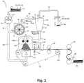
- FIG. 3 is a pattern diagram showing the schematic structure of the paper recycling device of another embodiment of the present invention.
- constitutions given the same reference numbers as those of the previous embodiment are the same as the previous items, so we will omit a description thereof.
- the first point of this embodiment that differs from the previous embodiment is that with this embodiment, the air flow suctioned by the suction device 110 is led to the introduction port 31 of the dry type defibrator 30 using a fourth transport pipe 180.
- the coarsely crushed paper pieces from the coarse crusher 10 obtain air flow energization and enter into the dry type defibrator 30.
- the air velocity at the exhaust port 32 of the dry type defibrator 30 can be further increased compared to the air velocity of the previous embodiment.
- the air velocity at the introduction port 51 of the cyclone 50 can also be further increased compared to the air velocity of the previous embodiment, and an increase in the deinking efficiency of the cyclone 50 can be expected.
- the second point of this embodiment that differs from the previous embodiment is that with this embodiment, a suction unit 91 such as a blower or the like is provided in the third transport pipe 70, and the air flow exhausted from the upper exhaust port 55 of the cyclone 50 is further increased, and furthermore, the air velocity at the introduction port 51 of the cyclone 50 is further increased.
- the suction method of the blower at this time can be made to be at a level for which there will not be backflow at the cyclone outlet port, or can be made to drive continuously by repeatedly doing deinking with the cyclone outlet port temporarily blocked, and then opening the outlet port after stopping the blower.
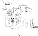
- FIG. 4 is a pattern diagram showing the schematic structure of the paper recycling device of another embodiment of the present invention.
- constitutions given the same reference numbers as the first embodiment shown in FIG. 1 are the same as the first items, so a description thereof is omitted.
- the first point of this embodiment that differs from the first embodiment is that with this embodiment, the air flow suctioned by the suction device 110 is led to the introduction port 31 of the dry type defibrator 30 using the fourth transport pipe 180.
- the coarsely crushed paper pieces from the coarse crusher 10 obtain air flow energization and enter into the dry type defibrator 30.
- the air velocity at the exhaust port 32 of the dry type defibrator 30 can be further increased compared to the air velocity of the first embodiment.
- the air velocity at the introduction port 51 of the cyclone 50 can also further be made higher than the air velocity of the first embodiment, and increased efficiency can be expected with the cyclone 50.
- the second point of this embodiment that differs from the first embodiment is that with this embodiment, the suction unit 91 such as a blower or the like is provided in the third transport pipe 70, and the air flow exhausted from the upper exhaust port 55 of the cyclone 50 is made to be increased further, and the air velocity at the introduction port 51 of the cyclone 50 is made to be further increased.
- the suction method of the blower at this time can be made to be at a level for which there will not be backflow at the cyclone outlet port, or can be made to drive continuously by repeatedly doing deinking with the cyclone outlet port temporarily blocked, and then opening the outlet port after stopping the blower.
- the third point of this embodiment that differs from the first embodiment is that with this embodiment, the first transport pipe 40 is constituted from a first diameter piping 41 and a second diameter piping 42 having a smaller pipe diameter than the first diameter piping 41.
- a first valve 43 is provided in the pipe path in the first diameter piping 41, and a second valve 44 is provided in the pipe path in the second diameter piping 42.
- the deinking efficiency in the case of a raw material with a large amount of relatively white paper or uncoated paper, or in the case when the deinking efficiency is relatively low, it is possible to operate using the piping 41 for which the speed is low at the cyclone introduction port, and conversely, when the ink adherence volume is large, or in the case of a raw material with a large amount of coated paper, to make the deinking efficiency high, it is possible to operate using the high speed piping 42.
- the first valve 43 in the first diameter piping 41 and the second valve 44 in the second diameter piping 42 function as the previously noted adjustment unit. With this kind of embodiment, it is possible select the deinking efficiency that is required as appropriate.
- the paper recycling device and the paper recycling method of the present invention do air classification of the old paper fibers into ink grains and deinked fibers using the classifier unit, and paper is formed with the deinked fibers, so with the paper recycling device and the paper recycling method of the present invention, it is possible to recycle paper that has a higher level of whiteness that can be used widely for applications other than paper for newspapers.
- the paper recycling device and the paper recycling method of the present invention it is possible to make the device more compact, and possible to install it in an office, so it is possible to perform paper recycling simultaneously with confidential document processing in small volumes that occur with relatively small offices.
- the constitution is such that to the extent possible it does not use water, so the device constitution is such that it is possible to reduce the water processing equipment and make the device constitution simple, and furthermore, a large scale heater or the like for drying water is not needed, so the energy efficiency with old paper recycling is high.
- the paper recycling device and the paper recycling method of the present invention is an item that matches this kind of need, and can be expected to greatly increase social usability.
- wet type method old paper recycling methods were used, and with this, it was essential to collect a large volume of old paper, and in addition to a great deal of effort being required for water processing equipment preparation and maintenance, there was also the problem that a great deal of energy was used for the drying process.
- deinking is performed using a classifier unit, and almost no water needs to be used, so it is possible to perform paper recycling simultaneously with processing of confidential documents in small volumes that occur in relatively small offices, and it is also possible to recycle paper with an increased whiteness level, and to have very high industrial applicability.
Description
- The present invention relates to a paper recycling device and paper recycling method based on paper recycling technology using a dry method that to the extent possible does not use water.
- In the past, with recycling of old paper discharged from offices or the like, a so-called wet method was used by which old paper was put into water, defibrated using mainly mechanical action, and remade. This kind of wet method old paper recycling requires a large volume of water, so the processing scale has to be large to make it inexpensive. Because of that, collecting a large volume of old paper is essential, and in addition to a great deal of effort being required for preparation and maintenance of the water processing equipment, there was also the problem that a large volume of energy is used for the drying process.
- However, since old paper on which confidential items are noted is also discharged from offices, from the perspective of maintaining confidentiality as well, there is a desire to process old paper within one's own office. However, since the volume of old paper discharged from a small office is small, it is difficult to ensure the volume necessary for a large scale process like that described above. Also, it is not realistic to install equipment for large scale processing like that noted above within an office. In light of that, to do paper recycling, up to now, several dry method paper recycling technologies that to the extent possible do not use water have been proposed.
- For example, disclosed with the invention noted in Patent Document 1 (Unexamined Patent Publication No.
1-148888 - Patent Document 1: Unexamined Patent Publication No.
1-148888 -
WO 00/71810 A1 US 4,668,339 A is further prior art. - However, the paper that is recycled using the technology noted in Patent Document 1 has not gone through the so-called deinking process that removes components of ink grains and the like contained in the fiber obtained by defibrating old paper, so there was the problem that the whiteness level was low, and its applicability was limited to paper for printing newspapers or the like.
- The invention is defined by claims 1 and 7.
- To address problems such as those noted above, the present invention is characterized in that the paper recycling device of the present invention has a dry type defibrator unit for crushing paper and defibrating it, a first transport unit for conveying defibrated material defibrated by the dry type defibrator unit, a classifier unit that does deinking by doing air flow classification of the defibrated material transported by the first transport unit, a second transport unit that transports the defibrated material deinked by the classifier unit, and a paper forming unit that forms paper with the defibrated material transported by the second transport unit.
- Also, with the paper recycling device of the present invention, the flow velocity of the air flow of the classifier unit's connecting part with the first transport unit is higher than the flow velocity of the air flow of the dry type defibrator unit's connecting part with the first transport unit.
- Also, with the paper recycling device of the present invention, the classifier unit is a cyclone.
- Also, with the paper recycling device of the present invention, the paper forming unit has a dispersion member for dispersing in the air the defibrated material transported by the second transport unit, a suction member for suctioning the dispersed defibrated material, and a mesh belt for transporting the defibrated material suctioned by the suction member.
- Also, with the paper recycling device of the present invention, the mesh belt transports the formed paper and also has a water sprayer for spraying water on the formed paper.
- Also, the paper recycling device of the present invention has a heater roller for heating the paper sprayed by water using the water sprayer.
- Also, the paper recycling device of the present invention has a third transport unit for transporting classified material classified from the defibrated material by the classifier unit, and a suction unit that suctions the classified material transported by the third transport unit.
- Also, the paper recycling method of the present invention is characterized by defibrating paper by dry type crushing, transporting the defibrated material using the first transport unit, doing air flow classification and deinking of the defibrated material transported by the first transport unit, transporting by the second transport unit the defibrated material deinked by the classifying process, and forming paper using the defibrated material transported by the second transport unit.
- Also, the paper recycling device of the present invention is characterized by having a dry type defibrator unit for doing dry type crushing and defibrating of paper, a first transport unit for transporting using air flow the defibrated material defibrated by the dry type defibrator unit, an adjustment unit for adjusting the air flow of the first transport unit, a classifier unit for doing air flow classification and deinking of the defibrated material transported by the first transport unit, a second transport unit for transporting the defibrated material deinked by the classifier unit, and a paper forming unit for forming paper from the defibrated material transported by the second transport unit.
- Also, with the paper recycling device of the present invention, the first transport unit has a transport pipe for moving defibrated material, and the adjustment unit adjusts the cross section surface area of the transport pipe.
- Also, with the paper recycling device of the present invention, the flow velocity of the air flow of the classifier unit's connecting part with the first transport unit is greater than the flow velocity of the air flow of the dry type defibrator unit's connecting part with the first transport unit.
- Also, with the paper recycling device of the present invention, the classifier unit is a cyclone.
- Also, with the paper recycling device of the present invention, the paper forming unit has a dispersion member for dispersing defibrated material, a suction member for suctioning the dispersed defibrated material, and a mesh belt for transporting the defibrated material suctioned by the suction member.
- Also, with the paper recycling device of the present invention, the mesh belt transports the formed paper, and also has a water sprayer for spraying water on the paper transported by the mesh belt.
- Also, the paper recycling device of the present invention has a heater roller for heating the paper sprayed with water by the water sprayer.
- Also, the paper recycling method of the present method is characterized by doing dry type crushing and defibrating of paper, transporting the defibrated material using air flow for which the flow velocity was adjusted, doing air flow classification and deinking of the transported defibrated material, transporting the deinked defibrated material, and forming paper using the transported defibrated material.
- Also, the paper recycling device of the present invention is characterized by having a dry type defibrator unit that does dry type crushing and defibrating of the supplied paper, a first transport unit that transports the defibrated material that was defibrated by the dry type defibrator unit, a classifier unit that does air flow classification and deinking of the defibrated material transported by the first transport unit, a second transport unit that transports the defibrated material that was deinked by the classifier unit, a paper forming unit that forms paper with the defibrated material transported by the second transport unit, and a control unit that controls the volume of paper supplied to the dry type defibrator unit.
- Also, the paper recycling device of the present invention has a detector unit that detects the thickness of the paper formed by the paper forming unit, and the control unit controls the volume of paper supplied to the dry type defibrator unit based on the detection results of the detector unit.
- Also, with the paper recycling device of the present invention, the flow velocity of the air flow of the classifier unit's connecting part with the first transport unit is greater than the flow velocity of the air flow of the dry type defibrator unit's connecting part with the first transport unit.
- Also, with the paper recycling device of the present invention, the classifier unit is a cyclone.
- Also, with the paper recycling device of the present invention, the paper forming unit has a dispersion member that disperses defibrated material, a suction member that suctions the dispersed defibrated material, and a mesh belt that transports the defibrated material suctioned by the suction member.
- Also, with the paper recycling device of the present invention, the mesh belt transports the formed paper, and also has a water sprayer that sprays water on the paper transported by the mesh belt.
- Also, the paper recycling device of the present invention has a heater roller that heats the paper sprayed with water by the water sprayer.
- Also, the paper recycling method of the present invention is characterized by supplying a controlled volume of paper, doing dry type crushing and defibrating of the supplied paper, transporting the defibrated material, doing air flow classification and deinking of the transported defibrated material, transporting the deinked defibrated material, and forming paper with the transported defibrated material.
- As described above, the paper recycling device and paper recycling method of the present invention uses the classifier unit to do air flow classification of the old paper fibers into ink grains and deinked fibers, and forms paper with those deinked fibers, so with the paper recycling device and paper recycling method of the present invention, it is possible to recycle paper for which the level of whiteness has been increased and which can be used for a wide variety of applications other than for paper for newspapers.
-
- [
FIG. 1 ] is a pattern diagram showing the schematic structure of the paper recycling device of an embodiment of the present invention. - [
FIG. 2 ] is a drawing schematically showing the control block structure of the paper recycling device of the embodiment of the present invention. - [
FIG. 3 ] is a pattern diagram showing the schematic structure of the paper recycling device of another embodiment of the present invention. - [
FIG. 4 ] is a pattern diagram showing the schematic structure of the paper recycling device of another embodiment of the present invention. - Following, we will describe an embodiment of the present invention while referring to the drawings.
FIG. 1 is a pattern diagram showing the schematic structure of the paper recycling device of an embodiment of the present invention. The paper recycling device of this embodiment is based on technology for recycling old paper into new paper using a dry method that to the extent possible does not use water. - As the old paper supplied to the paper recycling device of this embodiment, for example, old paper of A4 size which is currently the mainstream in offices or the like is used. This kind of old paper is input to a
coarse crusher 10 of the paper recycling device, and the old paper is cut into paper pieces of several centimeters square by a coarse crushingblade 11 of thecoarse crusher 10. Also, it is preferable to provide anautomatic feed mechanism 5 for continuously inputting old paper in this kind ofcoarse crusher 10. Considering productivity, it is preferable that the input speed of theautomatic feed mechanism 5 be high, but if it is too high, the device for processing becomes very large, so it is desirable to be 10 to 100 ppm. - The coarse crushing
blade 11 of thecoarse crusher 10 can be handled by using a device such as one for which the cutting width of the blade of a normal shredder has been widened. Coarsely crushed paper pieces cut into several centimeters square by the coarse crushingblade 11 are led via a coarsely crushedpaper introduction pipe 20 from ahopper 12 to the defibrating process which is the next process. - The coarsely crushed
paper introduction pipe 20 is in communication with anintroduction port 31 of adry type defibrator 30, and the coarsely crushed paper led into thedry type defibrator 30 from theintroduction port 31 is defibrated between a rotatingrotor 34 and astator 33. Thedry type defibrator 30 is a mechanism that generates air flow, and the defibrated fibers ride this air flow and are led from anexhaust port 32 to afirst transport pipe 40. - Here, we will describe a specific example of the
dry type defibrator 30. For thedry type defibrator 30, for example, it is possible to use a dry type old paper defibrator device equipped with a disc refiner, a turbo mill (made by Turbo Kogyo Co., Ltd.), a ceren miller (made by Masuko Sangyo Co., Ltd.), or a wind generating mechanism such as that disclosed in Unexamined Patent Publication No.H06-93585 dry type defibrator 30 can be items discharged by a normal shredder, but when considering paper strength, it is better to be larger than the fine paper pieces for confidential processing discharged by a shredder (e.g. 4 mm to 5 mm wide), but when too large, it becomes difficult to input into thedry type defibrator 30, so items cut into several centimeters square are desirable. - Also, with the
dry type defibrator 30 equipped with a wind generating mechanism, using the air flow generated by itself, paper pieces are suctioned together with the air flow from theintroduction port 31, undergo defibrating processing, and are transported to theexhaust port 32 side. - For example, with the Impeller Mill 250 (made by Seishin Enterprise Co., Ltd.) which is a turbo mill format, by installing 12 blades at the output side, when at 8000 rpm (peripheral speed approximately 100 m/s), it is possible to generate wind volume of approximately 3 m3/min. The wind speed at the
introduction port 31 side at this time is approximately 4 m/s, and the paper pieces are introduced by riding this air flow. The introduced paper pieces are defibrated between the blades rotating at high speed and the stator, and are exhausted from theexhaust port 32. The exhaust speed is approximately 6.5 m/s at exhaustpipe diameter ø 100. - When using the
dry type defibrator 30 not equipped with a wind generating mechanism, it is acceptable to separately provide air flow leading the coarse paper pieces into theintroduction port 31. - With the defibrating process at the
dry type defibrator 30, defibrating pulp to a fiber form for which the shape of the paper pieces disappears is preferable because unevenness of the paper formed at the subsequent step is eliminated. At this time, coating materials and the like for paper such as printed ink or toner, bleed prevention agent or the like are also crushed, and are crushed until they become grains of several tens of µm (hereafter called ink grains). Therefore, the output from thedry type defibrator 30 is the fiber and ink grains obtained by defibrating the paper pieces. - Also, as the
dry type defibrator 30, for example, when using a disk refiner, blades are formed in the radial direction on a round disk surface, but it is desirable to use blades with an edge on the circumference. Also, for the gap of the rotating blades of therotor 34 side and the fixed blades of thestator 33, it is desirable to maintain approximately the paper piece thickness, for example approximately 100 to 150 µm. At this time, the defibrated material is moved to the outer circumference by the air flow generated by the rotating blades, and exhausted from theexhaust port 32. - The defibrated material which rode the air flow from the
exhaust port 32 of thedry type defibrator 30 is introduced to acyclone 50 from thefirst transport pipe 40. Here, midway in thefirst transport pipe 40 is provided a tubediameter reduction part 45. This tubediameter reduction part 45 functions as an adjustment unit for performing adjustment of the air flow which transports fibers at thefirst transport pipe 40. Specifically, with this kind of adjustment unit, by performing adjustment of the transport cross section of thefirst transport pipe 40, adjustment is performed of the air flow that transports fibers in thefirst transport pipe 40. As a result, the air velocity at theintroduction port 51 of thecyclone 50 is adjusted to be greater than the air velocity at theexhaust port 32 of thedry type defibrator 30. - The deinking process is implemented in the
cyclone 50, and the fibers transported by thefirst transport pipe 40 are classified by air flow into ink grains and deinked fibers. With the present invention, it is possible to use an air flow type classifier of another type instead of thecyclone 50, but among these, the cyclone is desirable because of its simple structure. As an air flow type classifier other than the cyclone, for example an elbow jet, an eddy classifier or the like can be used. The air flow type classifier generates a gyrating air flow, and separates and classifies mixed materials by size using centrifugal force, and it is possible to adjust the classification points by adjusting the air flow speed and the centrifugal force. - In terms of performing deinking using the
cyclone 50, the tangent line input method cyclone is desirable because it has a relatively simple structure. Thiscyclone 50 is constituted from theintroduction port 51, acylinder part 52 for which theintroduction port 51 is attached in the tangent line direction, aninverted cone part 53 following thecylinder part 52, alower outlet port 43 provided at the top of theinverted cone part 53, and anupper exhaust port 55 for doing fine powder exhaust provided at the top center of thecylinder part 52. The defibrated material riding on the air flow (mixed material of fibers and ink grains) is preferably introduced from theintroduction port 51 at approximately 10 to 20 m/s. - With the deinking process, the air flow on which the defibrated material is riding introduced from the
introduction port 51 of thecyclone 50 changes with circumference motion at thecylinder part 52 of outer diameter ø approximately 100 to 300 mm, centrifugal force is applied, and by the synergistic effect with air flow, fibers become entangled and become large, the ink grains are separated, move to theinverted cone part 53, and the separated ink grains are led out as fine powder together with air to theupper exhaust port 55, and thus deinking advances. - However, it is advantageous for the introduction speed of the air flow on which defibrated material is riding to the
cyclone 50 to be fast. Also, if the speed of the cyclone introduction unit is lower than the exhaust air speed of thedry type defibrator 30, then defibrated material is retained inside thefirst transport pipe 40, the density per unit length of the introduction unit to thecyclone 50 becomes high and the deinking performance decreases. - In light of that, with the paper recycling device of the present invention, the tube
diameter reduction part 45 is provided midway in thefirst transport pipe 40, and the air velocity at theintroduction port 51 of thecyclone 50 is adjusted so as to be greater than the air velocity at theexhaust port 32 of thedry type defibrator 30. - Following, we will give a description using a specific example. The fine powder recovery volume recovered by the
cyclone 50 was 2.9 weight % (with the total volume of old paper supplied to the paper recycling device as 100 weight %) when the defibrated material exhausted from the dry type defibrator 30 (ø 100, cross section area approximately 78 cm2) was air classified by being introduced from theintroduction port 51 of thecyclone 50 from thefirst transport pipe 40 having (1) a 100 mm x 50 mm constant square cross section (cross section area approximately 50 cm2), and the whiteness level of the paper recycled at the forming step later was 82 (Xlite-L value). Also, at this time, the air velocity at theintroduction port 51 of thecyclone 50 was 10 m/s. - The fine powder recovery volume recovered by the
cyclone 50 was 3.8 weight % (with the total volume of old paper supplied to the paper recycling device as 100 weight %) when the defibrated material exhausted from thedry type defibrator 30 was air classified by being introduced from theintroduction port 51 of thecyclone 50 from thefirst transport pipe 40 having (2) a tubediameter reduction part 45 with a square cross section of from 100 mm x 50 mm to a square cross section of 100 mm x 40 mm (cross section area approximately 40 cm2), and the whiteness level of the paper recycled at the forming step later was 88 (Xlite-L value). Also, at this time, the air velocity at theintroduction port 51 of thecyclone 50 was 12 m/s. - The fine powder recovery volume recovered by the
cyclone 50 was 4.9 weight % (with the total volume of old paper supplied to the paper recycling device as 100 weight %) when the defibrated material exhausted from thedry type defibrator 30 was air classified by being introduced from theintroduction port 51 of thecyclone 50 from thefirst transport pipe 40 having (3) a tubediameter reduction part 45 with a square cross section of from 100 mm x 50 mm to a square cross section of 100 mm x 30 mm (cross section area approximately 30 cm2), and the whiteness level of the paper recycled at the forming step later was 91 (Xlite-L value). Also, at this time, the air velocity at theintroduction port 51 of thecyclone 50 was 16.7 m/s. - The whiteness degree when recycled paper was formed without classifying the defibrated material exhausted from the
dry type defibrator 30 using thecyclone 50 was 79 (Xlite-L value). - In any of cases (1) through (3), a slight amount of flocculent short fiber was included in the fine powder recovered by the
cyclone 50, but a large volume of ink grains were included, and deinking was confirmed. - With the kind of deinking process described above, the material riding on the air flow and exhausted from the
upper exhaust port 55 with thecyclone 50 passes through athird transport pipe 70 and is recovered in a receivingunit 90. In the material recovered by this receivingunit 90, short fiber mixed material in which a large volume of ink grains is contained as described previously is recovered. - Also, with the deinking process noted above, the material exhausted from the
lower outlet port 54 of thecyclone 50 is deinked fiber, and this deinked fiber is introduced to apaper forming machine 100 from thesecond transport pipe 60. For thepaper forming machine 100, it is possible to use an item such as is described in Translation of Patent Publication No.2008-508443 . - We will describe a summary of the
paper forming machine 100. Thepaper forming machine 100, in summary, has a mechanism for uniformly dispersing deinked fibers in air, and a mechanism for suctioning the deinked fibers dispersed by this onto themesh belt 122. - A small hole screen is provided on the surface of a forming
drum 101 of thepaper forming machine 100, and deinked fibers are made to be discharged from this. Also, aneedle roll 102 capable of rotating is provided inside the formingdrum 101, and the deinked fibers are made to rise so as not to cause clogging of the small hole screen of the surface of the formingdrum 101. Two formingdrums 101 are made to be in communication at locations that are not illustrated. With the constitution like that described above, deinked fibers are dispersed uniformly in air. - Beneath the
paper forming machine 100, anendless mesh belt 122 is placed with the mesh formed stretched by atension roller 121. By rotating at least one of thetension rollers 121, thismesh belt 122 is made to move in the direction shown by the arrow in the drawing. Also, themesh belt 122 has dirt and the like on its surface removed by acleaning blade 123 that abuts it. - Also, vertically downward from the two forming
drums 101 is provided asuction device 110 for generating air flow facing vertically downward in a form via themesh belt 122. The deinked fibers dispersed in air are suctioned onto themesh belt 122 by this kind ofsuction device 110. - With the kind of constitution described above, the deinked fibers transported by the
second transport pipe 60 are introduced into thepaper forming machine 100 to form paper. With thepaper forming machine 100, the deinked fibers are entangled in thecyclone 50, so they are untangled again by theneedle roll 102 or the like. The untangled deinked fibers pass through the small hole screen of the formingdrum 101 surface, and are deposited on themesh belt 122 by the suction force of thesuction device 110. At this time, by moving themesh belt 122, it is possible to deposit deinked defibrated material in an even sheet form. This deinked defibrated material becomes recycled paper (P). - Whether the
mesh belt 122 is metal, resin, or non-woven fabric, the deinked fibers can be deposited, and any material is acceptable as long as air flow can pass through, but if the hole diameter of the mesh is too large, dents and bumps occur when the paper P is formed, so it is preferable that the hole diameter be approximately 60 to 125 µ. Also, when 60 µ or less, it is difficult to form a stable air flow with thesuction device 110. For thesuction device 110, it is possible to form a sealed box with windows of the desired size opened below themesh belt 122, and to form it by making the inside of the box a vacuum by suctioning the air from outside the window. - If a sheet for which deinked fibers are deposited on the
mesh belt 122 is pressed as is, the paper strength is insufficient, so the hydrogen bonding between fibers is enhanced by adding water by spraying using thewater sprayer 130. - After that, the recycled paper (P) sprayed with water by the
water sprayer 130 passes through aheater roller 140 along with movement of themesh belt 122, but by being heated and pressed by thisheater roller 140, the fiber gap is made shorter and the contact points between fibers becomes stronger. By doing this, the strength of the recycled paper (P) as paper is increased, and by drying the excess water, it is possible to make excellent paper. Drying is done by installing a heater inside the press roller, and it is preferable to do pressing and drying simultaneously. By adding a so-called paper strength enhancer such as starch, PVA or the like to the water sprayed by thewater sprayer 130, it is possible to enhance the paper strength. - The recycled paper (P) obtained as described above can be processed using a
calendar roller 150 to improve the surface smoothness. The recycled paper (P) processed using thecalendar roller 150 is cut to the desired size using acutter 160, and is loaded using astacker 170 or the like. - We will describe an example of control of the paper recycling device constituted as described above.
FIG. 2 is a drawing schematically showing the constitution of the control block of the paper recycling device of an embodiment of the present invention. InFIG. 2 , themain control unit 200 is a main controller for performing various controls of the paper recycling device of the present invention. Using a general purpose information processing device equipped with a CPU and RAM, ROM or the like, it is possible to realize this kind ofmain control unit 200 by storing in advance in a ROM program that has the CPU execute the operation of outputting commands to a designated block based on designated information that has been input. - The detection results by the
thickness sensor 190 that detects the thickness of the deinked defibrated material deposited on themesh belt 122 are input to themain control unit 200 like that noted above. With themain control unit 150, the detection results data output from thethickness sensor 190 are processed, and are used for controlling the paper recycling device. - Also, the
main control unit 200 is made to output control instruction signals for controlling the feeding speed of old paper with theautomatic feed mechanism 5, and when these are received at theautomatic feed mechanism 5, the feeding speed of the old paper is adjusted based on these. - Also, the
main control unit 200 is made to output control instruction signals for controlling the rotation speed of therotor 34 of thedry type defibrator 30, and when these are received by thedry type defibrator 30, the rotation speed of therotor 34 is adjusted based on these. - Also, the
main control unit 200 is made to output control instruction signals for controlling the paper forming process speed with thepaper forming machine 100, and when these are received at thepaper forming machine 100, the process speed is adjusted based on these. - Also, the
main control unit 200 is made to output control instruction signals for controlling the suction force of thesuction device 110, and when these are received by thesuction device 100, the suction force is adjusted based on these. - Next, we will describe an example of control of the paper recycling device constituted as described above. For the recycled paper obtained with the paper recycling device of the present invention, the basis weight is determined by the volume of deinked fiber deposited on the
mesh belt 122. - The basis weight of the old paper input to the device by the
automatic feed mechanism 5, for example, is not fixed, ranging from thin paper of approximately 60 g to thick paper of approximately 120 g, so if the input old paper is input at a fixed number of sheets, the volume of processed fiber will vary, and the basis weight of the produced paper will also vary. - Also, for the deinking process, the deinking volume also varies by the volume of crushed ink, so the volume that goes to the fine powder side (
upper exhaust port 55 side) of thecyclone 50 also varies, and as a result, the volume of obtained deinked defibrated material also varies, and this leads to variation in the paper basis weight. - In light of that, with this embodiment, the thickness of the deinked defibrated material deposited on the
mesh belt 122 is measured, and feedback is given for themesh belt 122 speed and the speed of the old paper input volume by theautomatic feed mechanism 5. - In specific terms, the device is started, and immediately after the deinked fiber is deposited on the
mesh belt 122, the thickness of the deposited material is measured by thethickness sensor 190, and when that measurement result does not reach a designated thickness, the mesh belt speed is slowed, and if it is still insufficient, the old paper input speed at theautomatic feed mechanism 5 is increased, and when it is a designated thickness or greater, the mesh belt speed is speeded up, and when it is still too much with that, the old paper input speed at theautomatic feed mechanism 5 is lowered. The designated thickness setting changes according to the defibrating strength of thedry type defibrator 30, the suction force of thesuction device 110, and the desired thickness of the completed recycled paper, but as a general guideline, it is possible to make recycled paper of approximately 100 to 150 µ when the deposited material thickness is approximately 4 to 5 mm. - In this way, with this embodiment, the thickness of the paper formed by the paper forming machine 100 (thickness of the deinked defibrated material) is detected by the
thickness sensor 190, and themain control unit 200 controls theautomatic feed mechanism 5 to adjust the speed of themesh belt 122 and the volume of paper supplied to thedry type defibrator 30 based on the detection results of thethickness sensor 190. By doing this, it is possible to obtain recycled paper of stable quality. - The paper recycling device and paper recycling method of the present invention like those described above have air classification of the old paper fibers into ink grains and deinked fibers done using a classifier unit such as the
cyclone 50 or the like, and paper is formed with the deinked fibers, so with the paper recycling device and the paper recycling method of the present invention, it is possible to recycle paper with an improved level of whiteness that can be used widely for purposes other than paper for newspapers. Also, with the paper recycling device and the paper recycling method of the present invention, it is possible to have minimal water for the water use, so even when the device is made more compact, compared to the wet type method, regardless of the drying time, high productivity of 10 ppm or greater is expected. - Next, we will describe another embodiment of the present invention.
FIG. 3 is a pattern diagram showing the schematic structure of the paper recycling device of another embodiment of the present invention. InFIG. 3 , constitutions given the same reference numbers as those of the previous embodiment are the same as the previous items, so we will omit a description thereof. - The first point of this embodiment that differs from the previous embodiment is that with this embodiment, the air flow suctioned by the
suction device 110 is led to theintroduction port 31 of thedry type defibrator 30 using afourth transport pipe 180. By doing this, the coarsely crushed paper pieces from thecoarse crusher 10 obtain air flow energization and enter into thedry type defibrator 30. With this kind of constitution, the air velocity at theexhaust port 32 of thedry type defibrator 30 can be further increased compared to the air velocity of the previous embodiment. Then, as a result, the air velocity at theintroduction port 51 of thecyclone 50 can also be further increased compared to the air velocity of the previous embodiment, and an increase in the deinking efficiency of thecyclone 50 can be expected. - Also, the second point of this embodiment that differs from the previous embodiment is that with this embodiment, a
suction unit 91 such as a blower or the like is provided in thethird transport pipe 70, and the air flow exhausted from theupper exhaust port 55 of thecyclone 50 is further increased, and furthermore, the air velocity at theintroduction port 51 of thecyclone 50 is further increased. As a result, it is possible to expect increased efficiency of deinking with thecyclone 50 beyond that of the previous embodiment. The suction method of the blower at this time can be made to be at a level for which there will not be backflow at the cyclone outlet port, or can be made to drive continuously by repeatedly doing deinking with the cyclone outlet port temporarily blocked, and then opening the outlet port after stopping the blower. - Next, we will describe another embodiment of the present invention.
FIG. 4 is a pattern diagram showing the schematic structure of the paper recycling device of another embodiment of the present invention. InFIG. 4 , constitutions given the same reference numbers as the first embodiment shown inFIG. 1 are the same as the first items, so a description thereof is omitted. - The first point of this embodiment that differs from the first embodiment is that with this embodiment, the air flow suctioned by the
suction device 110 is led to theintroduction port 31 of thedry type defibrator 30 using thefourth transport pipe 180. By doing this, the coarsely crushed paper pieces from thecoarse crusher 10 obtain air flow energization and enter into thedry type defibrator 30. With this kind of constitution, the air velocity at theexhaust port 32 of thedry type defibrator 30 can be further increased compared to the air velocity of the first embodiment. Then, as a result, the air velocity at theintroduction port 51 of thecyclone 50 can also further be made higher than the air velocity of the first embodiment, and increased efficiency can be expected with thecyclone 50. - The second point of this embodiment that differs from the first embodiment is that with this embodiment, the
suction unit 91 such as a blower or the like is provided in thethird transport pipe 70, and the air flow exhausted from theupper exhaust port 55 of thecyclone 50 is made to be increased further, and the air velocity at theintroduction port 51 of thecyclone 50 is made to be further increased. As a result, increased efficiency of deinking with thecyclone 50 can be expected beyond that of the first embodiment. The suction method of the blower at this time can be made to be at a level for which there will not be backflow at the cyclone outlet port, or can be made to drive continuously by repeatedly doing deinking with the cyclone outlet port temporarily blocked, and then opening the outlet port after stopping the blower. - Also, the third point of this embodiment that differs from the first embodiment is that with this embodiment, the
first transport pipe 40 is constituted from a first diameter piping 41 and a second diameter piping 42 having a smaller pipe diameter than the first diameter piping 41. Afirst valve 43 is provided in the pipe path in the first diameter piping 41, and asecond valve 44 is provided in the pipe path in the second diameter piping 42. - With this embodiment, it is possible to select between leading the defibrated fibers using the first diameter piping 41 to the
introduction port 51 of thecyclone 50 by opening thefirst valve 43 and closing thesecond valve 44, or to lead the defibrated fibers using the second diameter piping 42 to theintroduction port 51 of thecyclone 50 by closing thefirst valve 43 and opening thesecond valve 44. With the latter, in the case of leading to theintroduction port 51 that leads fibers, it is possible to accelerate the air velocity at theintroduction port 51 compared to the former case. Specifically, in the case of a raw material with a large amount of relatively white paper or uncoated paper, or in the case when the deinking efficiency is relatively low, it is possible to operate using the piping 41 for which the speed is low at the cyclone introduction port, and conversely, when the ink adherence volume is large, or in the case of a raw material with a large amount of coated paper, to make the deinking efficiency high, it is possible to operate using thehigh speed piping 42. With this embodiment, thefirst valve 43 in the first diameter piping 41 and thesecond valve 44 in the second diameter piping 42 function as the previously noted adjustment unit. With this kind of embodiment, it is possible select the deinking efficiency that is required as appropriate. - Above, the paper recycling device and the paper recycling method of the present invention do air classification of the old paper fibers into ink grains and deinked fibers using the classifier unit, and paper is formed with the deinked fibers, so with the paper recycling device and the paper recycling method of the present invention, it is possible to recycle paper that has a higher level of whiteness that can be used widely for applications other than paper for newspapers.
- Also, with the paper recycling device and the paper recycling method of the present invention, it is possible to make the device more compact, and possible to install it in an office, so it is possible to perform paper recycling simultaneously with confidential document processing in small volumes that occur with relatively small offices.
- Also, with the paper recycling device and the paper recycling method of the present invention, the constitution is such that to the extent possible it does not use water, so the device constitution is such that it is possible to reduce the water processing equipment and make the device constitution simple, and furthermore, a large scale heater or the like for drying water is not needed, so the energy efficiency with old paper recycling is high.
- Also, with the paper recycling device and the paper recycling method of the present invention, it is possible to recycle paper in a relatively short time, so productivity is high.
- As we go forward, mechanisms that consider the earth's environment will be in increasing demand, and the paper recycling device and the paper recycling method of the present invention is an item that matches this kind of need, and can be expected to greatly increase social usability. Until now, with recycling of old paper exhausted from offices or the like, mainly, wet type method old paper recycling methods were used, and with this, it was essential to collect a large volume of old paper, and in addition to a great deal of effort being required for water processing equipment preparation and maintenance, there was also the problem that a great deal of energy was used for the drying process. In contrast to this, with the paper recycling device and the paper recycling method of the present invention, deinking is performed using a classifier unit, and almost no water needs to be used, so it is possible to perform paper recycling simultaneously with processing of confidential documents in small volumes that occur in relatively small offices, and it is also possible to recycle paper with an increased whiteness level, and to have very high industrial applicability.
-
- 5
- Automatic feed mechanism
- 10
- Coarse crusher
- 11
- Coarse crushing blade
- 12
- Hopper
- 20
- Coarsely crushed paper introduction pipe
- 30
- Dry type defibrator
- 31
- Introduction port
- 32
- Exhaust port
- 33
- Stator
- 34
- Rotor
- 40
- First transport pipe
- 45
- Tube diameter reduction part
- 50
- Cyclone
- 51
- Introduction port
- 52
- Cylinder part
- 53
- Inverted cone part
- 54
- Lower outlet port
- 55
- Upper exhaust port
- 60
- Second transport pipe
- 70
- Third transport pipe
- 90
- Receiving unit
- 91
- Suction unit
- 100
- Paper forming machine
- 101
- Forming drum
- 102
- Needle roll
- 110
- Suction device
- 121
- Tension roller
- 122
- Mesh belt
- 123
- Cleaning blade
- 130
- Water sprayer
- 140
- Heater roller
- 150
- Calendar roller
- 160
- Cutter
- 170
- Stacker
- 180
- Fourth transport pipe
- 190
- Thickness sensor
- 191
- Light emitting unit
- 192
- Light receiving unit
- 200
- Main control unit
Claims (7)
- A paper recycling device comprising:a dry type defibrator (30) for crushing paper and defibrating it,a first transport unit for conveying defibrated material defibrated by the dry type defibrator (30),a classifier unit that is arranged to do deinking of the defibrated material transported by the first transport unit,a second transport unit (60) that is arranged to transport the defibrated material deinked by the classifier unit, anda paper forming unit (100) that is arranged to form paper with the defibrated material transported by the second transport unit (60),wherein the classifier unit is arranged to do deinking by doing air flow classification of the defibrated material transported by the first transport unit,characterized in thatthe first transport unit comprises a first transport pipe (40) provided with an adjustment unit for performing adjustment of the transport cross section of the first transport pipe (40) and thereby performing adjustment of the air flow that transports fibers in the first transport pipe (40), so that the flow velocity of the air flow of the classifier unit's connecting part with the first transport unit is larger than the flow velocity of the air flow of the dry type defibrator unit's connecting part with the first transport unit.
- The paper recycling device according to claim 1, wherein the classifier unit is a cyclone (50).
- The paper recycling device according to any of claims 1 through 2, wherein the paper forming unit (100) has a dispersion member for dispersing in the air the defibrated material transported by the second transport unit (60), a suction member for suctioning the dispersed defibrated material, and a mesh belt (122) for transporting the defibrated material suctioned by the suction member.
- The paper recycling device according to claim 3, wherein the mesh belt (122) is arranged to transport the formed paper and also has a water sprayer (130) for spraying water on the formed paper.
- The paper recycling device according to claim 4, comprising a heater roller (140) for heating the paper sprayed by water using the water sprayer.
- The paper recycling device according to any of claims 1 through 5, comprising
a third transport unit (70) for transporting classified material classified from the defibrated material by the classifier unit, and
a suction unit (91) that is arranged to suction the classified material transported by the third transport unit (70). - A paper recycling method that
defibrates paper by dry type crushing,
transports the defibrated material using a first transport unit,
does air flow classification and deinking of the defibrated material transported by the first transport unit (40),
transports using a second transport unit (60) the defibrated material deinked by the classifying process, and
forms paper using the defibrated material transported by the second transport unit (60),
characterized in that
the first transport unit comprises a first transport pipe (40) provided with an adjustment unit for performing adjustment of the transport cross section of the first transport pipe (40) and thereby performing adjustment of the air flow that transports fibers in the first transport pipe (40), so that the air velocity at an air introduction port (51) of the classifier unit (50) which does the air flow classification and deinking is adjusted to be greater than the air velocity at an exhaust port (32) of a dry type defibrator (30) which defibrates paper.
Applications Claiming Priority (4)
| Application Number | Priority Date | Filing Date | Title |
|---|---|---|---|
| JP2011004113A JP5720255B2 (en) | 2011-01-12 | 2011-01-12 | Paper recycling apparatus and paper recycling method |
| JP2011005573A JP5720257B2 (en) | 2011-01-14 | 2011-01-14 | Paper recycling equipment |
| JP2011005574A JP5720258B2 (en) | 2011-01-14 | 2011-01-14 | Paper recycling apparatus and paper recycling method |
| PCT/JP2011/007124 WO2012095928A1 (en) | 2011-01-12 | 2011-12-20 | Paper recycling system and paper recycling process |
Publications (3)
| Publication Number | Publication Date |
|---|---|
| EP2664708A1 EP2664708A1 (en) | 2013-11-20 |
| EP2664708A4 EP2664708A4 (en) | 2014-07-23 |
| EP2664708B1 true EP2664708B1 (en) | 2017-04-12 |
Family
ID=46506855
Family Applications (1)
| Application Number | Title | Priority Date | Filing Date |
|---|---|---|---|
| EP11855915.2A Not-in-force EP2664708B1 (en) | 2011-01-12 | 2011-12-20 | Paper recycling system and paper recycling process |
Country Status (3)
| Country | Link |
|---|---|
| US (5) | US8882965B2 (en) |
| EP (1) | EP2664708B1 (en) |
| WO (1) | WO2012095928A1 (en) |
Cited By (1)
| Publication number | Priority date | Publication date | Assignee | Title |
|---|---|---|---|---|
| US20160168795A1 (en) * | 2014-12-12 | 2016-06-16 | Seiko Epson Corporation | Sheet manufacturing apparatus |
Families Citing this family (103)
| Publication number | Priority date | Publication date | Assignee | Title |
|---|---|---|---|---|
| EP2664708B1 (en) | 2011-01-12 | 2017-04-12 | Seiko Epson Corporation | Paper recycling system and paper recycling process |
| JP6213283B2 (en) | 2013-03-27 | 2017-10-18 | セイコーエプソン株式会社 | Sheet manufacturing equipment |
| JP2014208924A (en) | 2013-03-27 | 2014-11-06 | セイコーエプソン株式会社 | Sheet manufacturing apparatus |
| JP6213284B2 (en) | 2013-03-27 | 2017-10-18 | セイコーエプソン株式会社 | Sheet manufacturing equipment |
| JP2014208922A (en) * | 2013-03-27 | 2014-11-06 | セイコーエプソン株式会社 | Apparatus for manufacturing sheet and method for manufacturing sheet |
| JP2014208923A (en) | 2013-03-27 | 2014-11-06 | セイコーエプソン株式会社 | Sheet manufacturing apparatus |
| JP6393998B2 (en) * | 2013-03-27 | 2018-09-26 | セイコーエプソン株式会社 | Sheet manufacturing apparatus and sheet manufacturing apparatus control method |
| JP2014208925A (en) | 2013-03-27 | 2014-11-06 | セイコーエプソン株式会社 | Sheet manufacturing apparatus |
| JP6127882B2 (en) | 2013-10-01 | 2017-05-17 | セイコーエプソン株式会社 | Sheet manufacturing apparatus and sheet manufacturing method |
| JP6263931B2 (en) | 2013-10-01 | 2018-01-24 | セイコーエプソン株式会社 | Sheet manufacturing apparatus and sheet manufacturing method |
| JP6263933B2 (en) | 2013-10-03 | 2018-01-24 | セイコーエプソン株式会社 | Sheet manufacturing equipment |
| JP6277654B2 (en) | 2013-10-03 | 2018-02-14 | セイコーエプソン株式会社 | Sheet manufacturing equipment |
| JP6149662B2 (en) | 2013-10-03 | 2017-06-21 | セイコーエプソン株式会社 | Sheet manufacturing apparatus and sheet manufacturing method |
| JP6372065B2 (en) | 2013-10-09 | 2018-08-15 | セイコーエプソン株式会社 | Sheet manufacturing apparatus and defibrating unit |
| JP6191374B2 (en) * | 2013-10-09 | 2017-09-06 | セイコーエプソン株式会社 | Sheet manufacturing apparatus and defibrating unit |
| JP6127901B2 (en) | 2013-10-21 | 2017-05-17 | セイコーエプソン株式会社 | Sheet manufacturing apparatus and sheet manufacturing method |
| JP6354154B2 (en) | 2013-12-25 | 2018-07-11 | セイコーエプソン株式会社 | Sheet manufacturing equipment |
| JP2015120318A (en) * | 2013-12-25 | 2015-07-02 | セイコーエプソン株式会社 | Material defibration device, sheet producing device, and material defibration method |
| US9255360B2 (en) | 2013-12-25 | 2016-02-09 | Seiko Epson Corporation | Sheet manufacturing apparatus |
| JP6357767B2 (en) | 2013-12-25 | 2018-07-18 | セイコーエプソン株式会社 | Sheet manufacturing equipment |
| JP6248615B2 (en) * | 2013-12-25 | 2017-12-20 | セイコーエプソン株式会社 | Sheet manufacturing equipment |
| US9776213B2 (en) | 2013-12-25 | 2017-10-03 | Seiko Epson Corporation | Sheet manufacturing apparatus |
| US9562325B2 (en) * | 2013-12-27 | 2017-02-07 | Seiko Epson Corporation | Sheet manufacturing apparatus and sheet manufacturing method |
| JP6252171B2 (en) * | 2013-12-27 | 2017-12-27 | セイコーエプソン株式会社 | Sheet manufacturing apparatus and sheet manufacturing method |
| JP6507468B2 (en) | 2014-01-23 | 2019-05-08 | セイコーエプソン株式会社 | Paper manufacturing apparatus, paper manufacturing method and paper |
| JP6127992B2 (en) | 2014-01-23 | 2017-05-17 | セイコーエプソン株式会社 | Sheet manufacturing apparatus and sheet manufacturing method |
| JP6364804B2 (en) | 2014-02-14 | 2018-08-01 | セイコーエプソン株式会社 | Sheet manufacturing equipment, raw material defibrating equipment |
| JP6252232B2 (en) * | 2014-02-21 | 2017-12-27 | セイコーエプソン株式会社 | Sheet manufacturing apparatus and sheet manufacturing method |
| JP6248691B2 (en) | 2014-02-21 | 2017-12-20 | セイコーエプソン株式会社 | Sheet manufacturing equipment, defibrating machine |
| JP6248690B2 (en) * | 2014-02-21 | 2017-12-20 | セイコーエプソン株式会社 | Sheet manufacturing apparatus and sheet manufacturing method |
| JP6500329B2 (en) * | 2014-02-26 | 2019-04-17 | セイコーエプソン株式会社 | Sheet manufacturing equipment |
| JP2015161047A (en) * | 2014-02-28 | 2015-09-07 | セイコーエプソン株式会社 | Sheet production apparatus |
| JP6287365B2 (en) * | 2014-03-07 | 2018-03-07 | セイコーエプソン株式会社 | Sheet manufacturing equipment |
| JP6269181B2 (en) | 2014-03-07 | 2018-01-31 | セイコーエプソン株式会社 | Sheet manufacturing equipment |
| JP6065864B2 (en) | 2014-03-20 | 2017-01-25 | セイコーエプソン株式会社 | Sheet manufacturing apparatus and sheet manufacturing method |
| JP6361209B2 (en) * | 2014-03-25 | 2018-07-25 | セイコーエプソン株式会社 | Sheet manufacturing apparatus, sheet manufacturing method and sheet |
| JP6172128B2 (en) * | 2014-03-25 | 2017-08-02 | セイコーエプソン株式会社 | Sheet manufacturing equipment |
| JP6269235B2 (en) * | 2014-03-26 | 2018-01-31 | セイコーエプソン株式会社 | Sheet manufacturing equipment |
| JP6264986B2 (en) * | 2014-03-26 | 2018-01-24 | セイコーエプソン株式会社 | Sheet manufacturing equipment |
| JP6277836B2 (en) * | 2014-04-09 | 2018-02-14 | セイコーエプソン株式会社 | Sheet manufacturing equipment |
| JP6442857B2 (en) * | 2014-04-14 | 2018-12-26 | セイコーエプソン株式会社 | Sheet manufacturing equipment |
| WO2016035313A1 (en) * | 2014-09-05 | 2016-03-10 | セイコーエプソン株式会社 | Sheet manufacturing device and sheet manufacturing method |
| US9920478B2 (en) | 2014-09-05 | 2018-03-20 | Seiko Epson Corporation | Sheet manufacturing apparatus and sheet manufacturing method |
| JP6344167B2 (en) * | 2014-09-11 | 2018-06-20 | セイコーエプソン株式会社 | Sheet manufacturing apparatus and sheet manufacturing method |
| JP6439347B2 (en) * | 2014-09-25 | 2018-12-19 | セイコーエプソン株式会社 | Sheet manufacturing equipment |
| JP6485626B2 (en) | 2014-10-30 | 2019-03-20 | セイコーエプソン株式会社 | Sheet manufacturing apparatus and sheet manufacturing method |
| JP6500401B2 (en) | 2014-11-26 | 2019-04-17 | セイコーエプソン株式会社 | Sheet manufacturing equipment |
| JP6492576B2 (en) | 2014-11-26 | 2019-04-03 | セイコーエプソン株式会社 | Sheet manufacturing equipment |
| US9890500B2 (en) | 2014-11-26 | 2018-02-13 | Seiko Epson Corporation | Sheet manufacturing apparatus |
| JP6531381B2 (en) * | 2014-12-15 | 2019-06-19 | セイコーエプソン株式会社 | Sheet manufacturing apparatus and sheet manufacturing method |
| JP6464717B2 (en) * | 2014-12-17 | 2019-02-06 | セイコーエプソン株式会社 | Sheet manufacturing apparatus and sheet manufacturing method |
| JP6511803B2 (en) * | 2014-12-25 | 2019-05-15 | セイコーエプソン株式会社 | Sheet manufacturing apparatus, sheet manufacturing method |
| US9662658B2 (en) | 2015-01-09 | 2017-05-30 | Seiko Epson Corporation | Sheet manufacturing apparatus, paper supplying device, and paper shredding device |
| JP6512396B2 (en) | 2015-01-29 | 2019-05-15 | セイコーエプソン株式会社 | Sheet manufacturing apparatus and sheet manufacturing method |
| JP6511839B2 (en) | 2015-02-02 | 2019-05-15 | セイコーエプソン株式会社 | Sheet manufacturing apparatus and sheet manufacturing method |
| JP6547323B2 (en) | 2015-02-16 | 2019-07-24 | セイコーエプソン株式会社 | Method of calculating charging charge for sheet manufacturing apparatus, charging charge calculation device, charging system |
| JP6589298B2 (en) | 2015-03-04 | 2019-10-16 | セイコーエプソン株式会社 | Sheet manufacturing apparatus and sheet manufacturing method |
| JP6485124B2 (en) * | 2015-03-06 | 2019-03-20 | セイコーエプソン株式会社 | Sheet manufacturing equipment |
| EP3070202B1 (en) | 2015-03-18 | 2017-12-06 | Seiko Epson Corporation | Sheet manufacturing apparatus and sheet manufacturing method |
| JP6589335B2 (en) * | 2015-03-30 | 2019-10-16 | セイコーエプソン株式会社 | Sheet manufacturing apparatus and sheet manufacturing method |
| EP3346036B1 (en) | 2015-09-04 | 2021-07-07 | Seiko Epson Corporation | Sheet production apparatus and sheet production method |
| EP3348691B1 (en) * | 2015-09-11 | 2020-05-20 | Seiko Epson Corporation | Sheet production device and sheet production method |
| EP3385424B1 (en) | 2015-11-30 | 2022-10-12 | Seiko Epson Corporation | Sheet manufacturing device, control method for sheet manufacturing device, and method for manufacturing sheet |
| US10730711B2 (en) * | 2016-06-30 | 2020-08-04 | Seiko Epson Corporation | Paper sheet recycling and printing apparatus, printing apparatus, and paper sheet recycling apparatus |
| WO2018043019A1 (en) * | 2016-08-31 | 2018-03-08 | セイコーエプソン株式会社 | Sheet manufacturing device, and control method of sheet manufacturing device |
| US11005133B2 (en) | 2016-08-31 | 2021-05-11 | Seiko Epson Corporation | Sheet manufacturing apparatus and control method for sheet manufacturing apparatus |
| US11135540B2 (en) * | 2016-11-29 | 2021-10-05 | Seiko Epson Corporation | Dust collecting device and sheet manufacturing apparatus |
| WO2018159578A1 (en) * | 2017-03-01 | 2018-09-07 | セイコーエプソン株式会社 | Sheet manufacturing device, method for controlling same, and sheet manufacturing method |
| JP7047442B2 (en) * | 2017-03-01 | 2022-04-05 | セイコーエプソン株式会社 | Sheet manufacturing equipment |
| JP6965529B2 (en) * | 2017-03-07 | 2021-11-10 | セイコーエプソン株式会社 | Sheet processing equipment and management system |
| JP7035325B2 (en) * | 2017-03-22 | 2022-03-15 | セイコーエプソン株式会社 | Sheet manufacturing equipment, seats, and sheet manufacturing methods |
| JP6879106B2 (en) | 2017-07-31 | 2021-06-02 | セイコーエプソン株式会社 | Fiber defibrated product manufacturing equipment and sheet manufacturing equipment |
| JP6969195B2 (en) * | 2017-07-31 | 2021-11-24 | セイコーエプソン株式会社 | Defibering material manufacturing equipment and sheet manufacturing equipment |
| JP2019065407A (en) | 2017-09-28 | 2019-04-25 | セイコーエプソン株式会社 | Sheet production apparatus |
| CN109629288B (en) | 2017-09-28 | 2021-02-12 | 精工爱普生株式会社 | Fiber-opening device and sheet-manufacturing device |
| JP6418309B2 (en) * | 2017-11-22 | 2018-11-07 | セイコーエプソン株式会社 | Sheet manufacturing equipment |
| EP4345208A2 (en) * | 2018-01-15 | 2024-04-03 | Voith Patent GmbH | Method and device for producing a fiber mat |
| JP7035551B2 (en) * | 2018-01-18 | 2022-03-15 | セイコーエプソン株式会社 | Fiber processing equipment, fiber raw material recycling equipment, and control method of fiber processing equipment |
| JP7003792B2 (en) | 2018-03-28 | 2022-02-10 | セイコーエプソン株式会社 | Web forming equipment, web forming method and sheet manufacturing equipment |
| CN109024025B (en) * | 2018-09-12 | 2020-10-16 | 王晨宇 | Waste paper regeneration process method |
| US11040560B2 (en) | 2018-11-27 | 2021-06-22 | Seiko Epson Corporation | Waste paper recycling apparatus and waste paper recycling method |
| CN111218829A (en) | 2018-11-27 | 2020-06-02 | 精工爱普生株式会社 | Method and apparatus for forming fibrous body |
| JP7268353B2 (en) * | 2018-12-28 | 2023-05-08 | セイコーエプソン株式会社 | Swirling flow forming device and deposition device |
| JP7225834B2 (en) | 2019-01-24 | 2023-02-21 | セイコーエプソン株式会社 | Coarse crusher |
| US11162215B2 (en) * | 2019-03-20 | 2021-11-02 | Seiko Epson Corporation | Defibration treatment apparatus and fiber processing apparatus |
| JP7427922B2 (en) * | 2019-03-20 | 2024-02-06 | セイコーエプソン株式会社 | Defibration processing equipment and fiber processing equipment |
| JP7354598B2 (en) | 2019-06-07 | 2023-10-03 | セイコーエプソン株式会社 | Fibrous body forming method and fibrous body forming apparatus |
| DE102019005550A1 (en) * | 2019-08-07 | 2021-02-11 | Hubert Hergeth | Suction angle |
| JP2021063311A (en) | 2019-10-11 | 2021-04-22 | セイコーエプソン株式会社 | Fiber body production apparatus and fiber body production method |
| CN110820397B (en) * | 2019-11-14 | 2021-07-16 | 陈先金 | Production method of dry paper pulp |
| JP7400394B2 (en) | 2019-11-25 | 2023-12-19 | セイコーエプソン株式会社 | Defibration method and fibrous body forming method |
| JP2021085112A (en) | 2019-11-27 | 2021-06-03 | セイコーエプソン株式会社 | Method and apparatus for forming fiber body |
| JP2021085129A (en) * | 2019-11-29 | 2021-06-03 | セイコーエプソン株式会社 | Method and apparatus for forming fiber body, and a sheet |
| CN111068854B (en) * | 2019-12-31 | 2021-02-26 | 杭州振铭实业有限公司 | Corrugated container board's cutting breaker |
| CN111975896B (en) * | 2020-08-27 | 2022-06-07 | 博湖县隆源木业有限公司 | Leftover material recycling device and method for wood processing |
| JP2022056063A (en) | 2020-09-29 | 2022-04-08 | セイコーエプソン株式会社 | Sheet production equipment |
| JP2022055784A (en) | 2020-09-29 | 2022-04-08 | セイコーエプソン株式会社 | Molded article manufacturing method |
| JP2022104408A (en) * | 2020-12-28 | 2022-07-08 | セイコーエプソン株式会社 | Powder recovery device and fiber body processor |
| JP2022156206A (en) | 2021-03-31 | 2022-10-14 | セイコーエプソン株式会社 | Method for producing sheet, and apparatus for producing sheet |
| JP2022156207A (en) | 2021-03-31 | 2022-10-14 | セイコーエプソン株式会社 | Method for producing sheet, and apparatus for producing sheet |
| JP2022176652A (en) | 2021-05-17 | 2022-11-30 | セイコーエプソン株式会社 | Apparatus for producing sheet, and method for producing sheet |
| DE102021125451A1 (en) * | 2021-09-30 | 2023-03-30 | Voith Patent Gmbh | Method and machine for producing a fibrous web in a paper machine |
| CN114918028B (en) * | 2022-05-24 | 2024-03-15 | 盐城璟甡电子科技有限公司 | Engineering machine for material processing |
Family Cites Families (21)
| Publication number | Priority date | Publication date | Assignee | Title |
|---|---|---|---|---|
| GB1206550A (en) * | 1969-06-04 | 1970-09-23 | Bergstrom Paper Co | Method of decontaminating reclaimed paper |
| DE2349065A1 (en) * | 1972-10-02 | 1974-04-18 | Black Clawson Co | PROCESS FOR RECOVERY OF PAPER FIBER |
| JPS5212805B2 (en) * | 1973-03-20 | 1977-04-09 | ||
| JPS545005B2 (en) | 1973-10-26 | 1979-03-13 | ||
| JPS52144407A (en) * | 1976-05-22 | 1977-12-01 | Mitsubishi Heavy Ind Ltd | Production of fibrous belt like substance |
| US4668339A (en) * | 1983-11-22 | 1987-05-26 | Kimberly-Clark Corporation | Process for dry deinking of secondary fiber sources |
| JPH01148888A (en) | 1987-12-03 | 1989-06-12 | Kimberly Clark Corp | Newspacer printing paper containing secondary fiber |
| JPH0693585A (en) | 1992-09-04 | 1994-04-05 | V M C:Kk | Dry type opener |
| JPH06155418A (en) | 1992-11-20 | 1994-06-03 | Nishimatsu Constr Co Ltd | Production of wooden material using old paper a raw material |
| JPH0726451A (en) | 1993-07-12 | 1995-01-27 | Kobe Steel Ltd | Dry papermaking from waste paper |
| JP3380010B2 (en) | 1993-09-29 | 2003-02-24 | 株式会社ブイエムシー | Dry defibration of used paper |
| US5564635A (en) | 1993-09-29 | 1996-10-15 | Kabushiki Kaisha Kobe Seiko Sho | Apparatus for dry disintegration of used paper |
| JPH07124498A (en) | 1993-10-22 | 1995-05-16 | Kobe Steel Ltd | Device for classifying and collecting fibrillated material for dry process waste paper fibrillating device |
| CA2123328A1 (en) * | 1993-12-13 | 1995-06-14 | Kimberly-Clark Worldwide, Inc. | Magnetic deinking |
| JPH1148888A (en) | 1997-08-08 | 1999-02-23 | Kasai Kogyo Co Ltd | Interior parts for automobile |
| CN1311836A (en) * | 1999-05-25 | 2001-09-05 | U.T.G环境技术有限公司 | Method and device for sorting paper mixtures |
| JP2001140184A (en) * | 1999-11-09 | 2001-05-22 | Kobayashi Eng Works Ltd | Method and apparatus for regulating product profile in cylinder paper making machine |
| US6782637B2 (en) * | 2001-10-30 | 2004-08-31 | Weyerhaeuser Company | System for making dried singulated crosslinked cellulose pulp fibers |
| US7334347B2 (en) * | 2001-10-30 | 2008-02-26 | Weyerhaeuser Company | Process for producing dried, singulated fibers using steam and heated air |
| DK175987B1 (en) | 2004-08-05 | 2005-10-31 | Dan Core Internat A S | Former head with rotating drum |
| EP2664708B1 (en) * | 2011-01-12 | 2017-04-12 | Seiko Epson Corporation | Paper recycling system and paper recycling process |
-
2011
- 2011-12-20 EP EP11855915.2A patent/EP2664708B1/en not_active Not-in-force
- 2011-12-20 US US13/979,089 patent/US8882965B2/en not_active Expired - Fee Related
- 2011-12-20 WO PCT/JP2011/007124 patent/WO2012095928A1/en active Application Filing
-
2014
- 2014-09-12 US US14/484,385 patent/US9194081B2/en not_active Expired - Fee Related
-
2015
- 2015-09-21 US US14/859,789 patent/US9435078B2/en active Active
-
2016
- 2016-07-29 US US15/223,431 patent/US9636847B2/en active Active
-
2017
- 2017-03-28 US US15/471,025 patent/US9890499B2/en not_active Expired - Fee Related
Non-Patent Citations (1)
| Title |
|---|
| None * |
Cited By (2)
| Publication number | Priority date | Publication date | Assignee | Title |
|---|---|---|---|---|
| US20160168795A1 (en) * | 2014-12-12 | 2016-06-16 | Seiko Epson Corporation | Sheet manufacturing apparatus |
| US9982391B2 (en) * | 2014-12-12 | 2018-05-29 | Seiko Epson Corporation | Sheet manufacturing apparatus |
Also Published As
| Publication number | Publication date |
|---|---|
| US9636847B2 (en) | 2017-05-02 |
| US20160332333A1 (en) | 2016-11-17 |
| EP2664708A1 (en) | 2013-11-20 |
| US20140374047A1 (en) | 2014-12-25 |
| US9435078B2 (en) | 2016-09-06 |
| US20170198434A1 (en) | 2017-07-13 |
| US9890499B2 (en) | 2018-02-13 |
| WO2012095928A1 (en) | 2012-07-19 |
| US20140027075A1 (en) | 2014-01-30 |
| US8882965B2 (en) | 2014-11-11 |
| US9194081B2 (en) | 2015-11-24 |
| US20160010278A1 (en) | 2016-01-14 |
| EP2664708A4 (en) | 2014-07-23 |
Similar Documents
| Publication | Publication Date | Title |
|---|---|---|
| US9890499B2 (en) | Paper recycling device and paper recycling method | |
| JP5720258B2 (en) | Paper recycling apparatus and paper recycling method | |
| JP5720255B2 (en) | Paper recycling apparatus and paper recycling method | |
| JP5720257B2 (en) | Paper recycling equipment | |
| EP2784210B1 (en) | Sheet manufacturing apparatus and method for manufacturing sheet | |
| JP6733779B2 (en) | Sheet manufacturing apparatus and method for controlling sheet manufacturing apparatus | |
| EP3061859B1 (en) | Sheet manufacturing device and sheet manufacturing method | |
| CN108866823B (en) | Sheet manufacturing apparatus | |
| US9574304B2 (en) | Sheet-manufacturing device and method for controlling sheet-manufacturing device | |
| JP2014208924A (en) | Sheet manufacturing apparatus | |
| CN105735027B (en) | Sheet manufacturing apparatus and sheet manufacturing method | |
| US10544530B2 (en) | Sheet manufacturing apparatus and sheet manufacturing method | |
| JP5910777B2 (en) | Paper recycling apparatus and paper recycling method | |
| JP2015120318A (en) | Material defibration device, sheet producing device, and material defibration method | |
| JP2018122558A (en) | Device and method for producing weeding sheet | |
| JP6349782B2 (en) | Confidential document processing device, sheet manufacturing device |
Legal Events
| Date | Code | Title | Description |
|---|---|---|---|
| PUAI | Public reference made under article 153(3) epc to a published international application that has entered the european phase |
Free format text: ORIGINAL CODE: 0009012 |
|
| 17P | Request for examination filed |
Effective date: 20130806 |
|
| AK | Designated contracting states |
Kind code of ref document: A1 Designated state(s): AL AT BE BG CH CY CZ DE DK EE ES FI FR GB GR HR HU IE IS IT LI LT LU LV MC MK MT NL NO PL PT RO RS SE SI SK SM TR |
|
| DAX | Request for extension of the european patent (deleted) | ||
| A4 | Supplementary search report drawn up and despatched |
Effective date: 20140620 |
|
| RIC1 | Information provided on ipc code assigned before grant |
Ipc: D21B 1/08 20060101AFI20140613BHEP Ipc: D21F 9/02 20060101ALI20140613BHEP Ipc: D21D 5/24 20060101ALI20140613BHEP Ipc: D21G 9/00 20060101ALI20140613BHEP Ipc: D21C 5/02 20060101ALI20140613BHEP |
|
| 17Q | First examination report despatched |
Effective date: 20160329 |
|
| REG | Reference to a national code |
Ref country code: DE Ref legal event code: R079 Ref document number: 602011037015 Country of ref document: DE Free format text: PREVIOUS MAIN CLASS: D21B0001080000 Ipc: D21F0007060000 |
|
| GRAP | Despatch of communication of intention to grant a patent |
Free format text: ORIGINAL CODE: EPIDOSNIGR1 |
|
| INTG | Intention to grant announced |
Effective date: 20170105 |
|
| RIC1 | Information provided on ipc code assigned before grant |
Ipc: D21C 5/02 20060101ALI20161216BHEP Ipc: D21G 9/00 20060101ALI20161216BHEP Ipc: D21F 9/02 20060101ALI20161216BHEP Ipc: B29B 13/00 20060101ALI20161216BHEP Ipc: D21H 11/14 20060101ALI20161216BHEP Ipc: D21F 7/06 20060101AFI20161216BHEP Ipc: B29L 7/00 20060101ALI20161216BHEP Ipc: D21D 5/24 20060101ALI20161216BHEP Ipc: D21B 1/08 20060101ALI20161216BHEP |
|
| GRAS | Grant fee paid |
Free format text: ORIGINAL CODE: EPIDOSNIGR3 |
|
| GRAA | (expected) grant |
Free format text: ORIGINAL CODE: 0009210 |
|
| AK | Designated contracting states |
Kind code of ref document: B1 Designated state(s): AL AT BE BG CH CY CZ DE DK EE ES FI FR GB GR HR HU IE IS IT LI LT LU LV MC MK MT NL NO PL PT RO RS SE SI SK SM TR |
|
| REG | Reference to a national code |
Ref country code: GB Ref legal event code: FG4D |
|
| REG | Reference to a national code |
Ref country code: CH Ref legal event code: EP |
|
| REG | Reference to a national code |
Ref country code: IE Ref legal event code: FG4D |
|
| REG | Reference to a national code |
Ref country code: AT Ref legal event code: REF Ref document number: 884005 Country of ref document: AT Kind code of ref document: T Effective date: 20170515 |
|
| REG | Reference to a national code |
Ref country code: DE Ref legal event code: R096 Ref document number: 602011037015 Country of ref document: DE |
|
| REG | Reference to a national code |
Ref country code: NL Ref legal event code: MP Effective date: 20170412 |
|
| REG | Reference to a national code |
Ref country code: LT Ref legal event code: MG4D |
|
| REG | Reference to a national code |
Ref country code: AT Ref legal event code: MK05 Ref document number: 884005 Country of ref document: AT Kind code of ref document: T Effective date: 20170412 |
|
| PG25 | Lapsed in a contracting state [announced via postgrant information from national office to epo] |
Ref country code: NL Free format text: LAPSE BECAUSE OF FAILURE TO SUBMIT A TRANSLATION OF THE DESCRIPTION OR TO PAY THE FEE WITHIN THE PRESCRIBED TIME-LIMIT Effective date: 20170412 |
|
| PG25 | Lapsed in a contracting state [announced via postgrant information from national office to epo] |
Ref country code: FI Free format text: LAPSE BECAUSE OF FAILURE TO SUBMIT A TRANSLATION OF THE DESCRIPTION OR TO PAY THE FEE WITHIN THE PRESCRIBED TIME-LIMIT Effective date: 20170412 Ref country code: GR Free format text: LAPSE BECAUSE OF FAILURE TO SUBMIT A TRANSLATION OF THE DESCRIPTION OR TO PAY THE FEE WITHIN THE PRESCRIBED TIME-LIMIT Effective date: 20170713 Ref country code: LT Free format text: LAPSE BECAUSE OF FAILURE TO SUBMIT A TRANSLATION OF THE DESCRIPTION OR TO PAY THE FEE WITHIN THE PRESCRIBED TIME-LIMIT Effective date: 20170412 Ref country code: AT Free format text: LAPSE BECAUSE OF FAILURE TO SUBMIT A TRANSLATION OF THE DESCRIPTION OR TO PAY THE FEE WITHIN THE PRESCRIBED TIME-LIMIT Effective date: 20170412 Ref country code: NO Free format text: LAPSE BECAUSE OF FAILURE TO SUBMIT A TRANSLATION OF THE DESCRIPTION OR TO PAY THE FEE WITHIN THE PRESCRIBED TIME-LIMIT Effective date: 20170712 Ref country code: ES Free format text: LAPSE BECAUSE OF FAILURE TO SUBMIT A TRANSLATION OF THE DESCRIPTION OR TO PAY THE FEE WITHIN THE PRESCRIBED TIME-LIMIT Effective date: 20170412 Ref country code: HR Free format text: LAPSE BECAUSE OF FAILURE TO SUBMIT A TRANSLATION OF THE DESCRIPTION OR TO PAY THE FEE WITHIN THE PRESCRIBED TIME-LIMIT Effective date: 20170412 |
|
| PG25 | Lapsed in a contracting state [announced via postgrant information from national office to epo] |
Ref country code: LV Free format text: LAPSE BECAUSE OF FAILURE TO SUBMIT A TRANSLATION OF THE DESCRIPTION OR TO PAY THE FEE WITHIN THE PRESCRIBED TIME-LIMIT Effective date: 20170412 Ref country code: IS Free format text: LAPSE BECAUSE OF FAILURE TO SUBMIT A TRANSLATION OF THE DESCRIPTION OR TO PAY THE FEE WITHIN THE PRESCRIBED TIME-LIMIT Effective date: 20170812 Ref country code: BG Free format text: LAPSE BECAUSE OF FAILURE TO SUBMIT A TRANSLATION OF THE DESCRIPTION OR TO PAY THE FEE WITHIN THE PRESCRIBED TIME-LIMIT Effective date: 20170712 Ref country code: RS Free format text: LAPSE BECAUSE OF FAILURE TO SUBMIT A TRANSLATION OF THE DESCRIPTION OR TO PAY THE FEE WITHIN THE PRESCRIBED TIME-LIMIT Effective date: 20170412 Ref country code: PL Free format text: LAPSE BECAUSE OF FAILURE TO SUBMIT A TRANSLATION OF THE DESCRIPTION OR TO PAY THE FEE WITHIN THE PRESCRIBED TIME-LIMIT Effective date: 20170412 Ref country code: SE Free format text: LAPSE BECAUSE OF FAILURE TO SUBMIT A TRANSLATION OF THE DESCRIPTION OR TO PAY THE FEE WITHIN THE PRESCRIBED TIME-LIMIT Effective date: 20170412 |
|
| REG | Reference to a national code |
Ref country code: FR Ref legal event code: PLFP Year of fee payment: 7 |
|
| REG | Reference to a national code |
Ref country code: DE Ref legal event code: R097 Ref document number: 602011037015 Country of ref document: DE |
|
| PG25 | Lapsed in a contracting state [announced via postgrant information from national office to epo] |
Ref country code: CZ Free format text: LAPSE BECAUSE OF FAILURE TO SUBMIT A TRANSLATION OF THE DESCRIPTION OR TO PAY THE FEE WITHIN THE PRESCRIBED TIME-LIMIT Effective date: 20170412 Ref country code: SK Free format text: LAPSE BECAUSE OF FAILURE TO SUBMIT A TRANSLATION OF THE DESCRIPTION OR TO PAY THE FEE WITHIN THE PRESCRIBED TIME-LIMIT Effective date: 20170412 Ref country code: RO Free format text: LAPSE BECAUSE OF FAILURE TO SUBMIT A TRANSLATION OF THE DESCRIPTION OR TO PAY THE FEE WITHIN THE PRESCRIBED TIME-LIMIT Effective date: 20170412 Ref country code: DK Free format text: LAPSE BECAUSE OF FAILURE TO SUBMIT A TRANSLATION OF THE DESCRIPTION OR TO PAY THE FEE WITHIN THE PRESCRIBED TIME-LIMIT Effective date: 20170412 Ref country code: EE Free format text: LAPSE BECAUSE OF FAILURE TO SUBMIT A TRANSLATION OF THE DESCRIPTION OR TO PAY THE FEE WITHIN THE PRESCRIBED TIME-LIMIT Effective date: 20170412 |
|
| PLBE | No opposition filed within time limit |
Free format text: ORIGINAL CODE: 0009261 |
|
| STAA | Information on the status of an ep patent application or granted ep patent |
Free format text: STATUS: NO OPPOSITION FILED WITHIN TIME LIMIT |
|
| PG25 | Lapsed in a contracting state [announced via postgrant information from national office to epo] |
Ref country code: SM Free format text: LAPSE BECAUSE OF FAILURE TO SUBMIT A TRANSLATION OF THE DESCRIPTION OR TO PAY THE FEE WITHIN THE PRESCRIBED TIME-LIMIT Effective date: 20170412 Ref country code: IT Free format text: LAPSE BECAUSE OF FAILURE TO SUBMIT A TRANSLATION OF THE DESCRIPTION OR TO PAY THE FEE WITHIN THE PRESCRIBED TIME-LIMIT Effective date: 20170412 |
|
| 26N | No opposition filed |
Effective date: 20180115 |
|
| PG25 | Lapsed in a contracting state [announced via postgrant information from national office to epo] |
Ref country code: SI Free format text: LAPSE BECAUSE OF FAILURE TO SUBMIT A TRANSLATION OF THE DESCRIPTION OR TO PAY THE FEE WITHIN THE PRESCRIBED TIME-LIMIT Effective date: 20170412 |
|
| REG | Reference to a national code |
Ref country code: CH Ref legal event code: PL |
|
| REG | Reference to a national code |
Ref country code: IE Ref legal event code: MM4A |
|
| PG25 | Lapsed in a contracting state [announced via postgrant information from national office to epo] |
Ref country code: MT Free format text: LAPSE BECAUSE OF NON-PAYMENT OF DUE FEES Effective date: 20171220 Ref country code: LU Free format text: LAPSE BECAUSE OF NON-PAYMENT OF DUE FEES Effective date: 20171220 |
|
| REG | Reference to a national code |
Ref country code: BE Ref legal event code: MM Effective date: 20171231 |
|
| PG25 | Lapsed in a contracting state [announced via postgrant information from national office to epo] |
Ref country code: IE Free format text: LAPSE BECAUSE OF NON-PAYMENT OF DUE FEES Effective date: 20171220 |
|
| PG25 | Lapsed in a contracting state [announced via postgrant information from national office to epo] |
Ref country code: CH Free format text: LAPSE BECAUSE OF NON-PAYMENT OF DUE FEES Effective date: 20171231 Ref country code: BE Free format text: LAPSE BECAUSE OF NON-PAYMENT OF DUE FEES Effective date: 20171231 Ref country code: LI Free format text: LAPSE BECAUSE OF NON-PAYMENT OF DUE FEES Effective date: 20171231 |
|
| PG25 | Lapsed in a contracting state [announced via postgrant information from national office to epo] |
Ref country code: HU Free format text: LAPSE BECAUSE OF FAILURE TO SUBMIT A TRANSLATION OF THE DESCRIPTION OR TO PAY THE FEE WITHIN THE PRESCRIBED TIME-LIMIT; INVALID AB INITIO Effective date: 20111220 Ref country code: MC Free format text: LAPSE BECAUSE OF FAILURE TO SUBMIT A TRANSLATION OF THE DESCRIPTION OR TO PAY THE FEE WITHIN THE PRESCRIBED TIME-LIMIT Effective date: 20170412 |
|
| PG25 | Lapsed in a contracting state [announced via postgrant information from national office to epo] |
Ref country code: CY Free format text: LAPSE BECAUSE OF NON-PAYMENT OF DUE FEES Effective date: 20170412 |
|
| PG25 | Lapsed in a contracting state [announced via postgrant information from national office to epo] |
Ref country code: MK Free format text: LAPSE BECAUSE OF FAILURE TO SUBMIT A TRANSLATION OF THE DESCRIPTION OR TO PAY THE FEE WITHIN THE PRESCRIBED TIME-LIMIT Effective date: 20170412 |
|
| PGFP | Annual fee paid to national office [announced via postgrant information from national office to epo] |
Ref country code: DE Payment date: 20191210 Year of fee payment: 9 |
|
| PGFP | Annual fee paid to national office [announced via postgrant information from national office to epo] |
Ref country code: FR Payment date: 20191115 Year of fee payment: 9 |
|
| PG25 | Lapsed in a contracting state [announced via postgrant information from national office to epo] |
Ref country code: TR Free format text: LAPSE BECAUSE OF FAILURE TO SUBMIT A TRANSLATION OF THE DESCRIPTION OR TO PAY THE FEE WITHIN THE PRESCRIBED TIME-LIMIT Effective date: 20170412 |
|
| PGFP | Annual fee paid to national office [announced via postgrant information from national office to epo] |
Ref country code: GB Payment date: 20191219 Year of fee payment: 9 |
|
| PG25 | Lapsed in a contracting state [announced via postgrant information from national office to epo] |
Ref country code: PT Free format text: LAPSE BECAUSE OF FAILURE TO SUBMIT A TRANSLATION OF THE DESCRIPTION OR TO PAY THE FEE WITHIN THE PRESCRIBED TIME-LIMIT Effective date: 20170412 |
|
| PG25 | Lapsed in a contracting state [announced via postgrant information from national office to epo] |
Ref country code: AL Free format text: LAPSE BECAUSE OF FAILURE TO SUBMIT A TRANSLATION OF THE DESCRIPTION OR TO PAY THE FEE WITHIN THE PRESCRIBED TIME-LIMIT Effective date: 20170412 |
|
| REG | Reference to a national code |
Ref country code: DE Ref legal event code: R119 Ref document number: 602011037015 Country of ref document: DE |
|
| GBPC | Gb: european patent ceased through non-payment of renewal fee |
Effective date: 20201220 |
|
| PG25 | Lapsed in a contracting state [announced via postgrant information from national office to epo] |
Ref country code: FR Free format text: LAPSE BECAUSE OF NON-PAYMENT OF DUE FEES Effective date: 20201231 |
|
| PG25 | Lapsed in a contracting state [announced via postgrant information from national office to epo] |
Ref country code: GB Free format text: LAPSE BECAUSE OF NON-PAYMENT OF DUE FEES Effective date: 20201220 Ref country code: DE Free format text: LAPSE BECAUSE OF NON-PAYMENT OF DUE FEES Effective date: 20210701 |