JP6439347B2 - Sheet manufacturing equipment - Google Patents
Sheet manufacturing equipment Download PDFInfo
- Publication number
- JP6439347B2 JP6439347B2 JP2014194909A JP2014194909A JP6439347B2 JP 6439347 B2 JP6439347 B2 JP 6439347B2 JP 2014194909 A JP2014194909 A JP 2014194909A JP 2014194909 A JP2014194909 A JP 2014194909A JP 6439347 B2 JP6439347 B2 JP 6439347B2
- Authority
- JP
- Japan
- Prior art keywords
- pressure roller
- unit
- web
- pressure
- pair
- Prior art date
- Legal status (The legal status is an assumption and is not a legal conclusion. Google has not performed a legal analysis and makes no representation as to the accuracy of the status listed.)
- Active
Links
Images


Classifications
-
- D—TEXTILES; PAPER
- D21—PAPER-MAKING; PRODUCTION OF CELLULOSE
- D21F—PAPER-MAKING MACHINES; METHODS OF PRODUCING PAPER THEREON
- D21F9/00—Complete machines for making continuous webs of paper
-
- D—TEXTILES; PAPER
- D21—PAPER-MAKING; PRODUCTION OF CELLULOSE
- D21F—PAPER-MAKING MACHINES; METHODS OF PRODUCING PAPER THEREON
- D21F3/00—Press section of machines for making continuous webs of paper
Landscapes
- Nonwoven Fabrics (AREA)
- Advancing Webs (AREA)
- Paper (AREA)
Description
本発明は、シート製造装置に関する。 The present invention relates to a sheet manufacturing apparatus.
従来、ソフトロールとヒーティングロールとで構成されたソフトカレンダーを用いて、抄紙機により抄造した紙を加圧しながら搬送する紙の製造方法が知られている(例えば、特許文献1参照)。 2. Description of the Related Art Conventionally, a paper manufacturing method is known in which a paper calendered by a paper machine is pressurized and conveyed using a soft calender composed of a soft roll and a heating roll (see, for example, Patent Document 1).
しかしながら、上記の紙の製造方法では、ソフトカレンダーの各ロール中心を結ぶ仮想線が紙の搬送方向に対して直交するようにソフトカレンダーが配置されているため、ソフトカレンダーによるニップ部の圧力により、搬送された紙がニップ部入口で滞留して垂れ下がり搬送不良が発生してしまう、という課題があった。 However, in the above paper manufacturing method, since the soft calendar is arranged so that the virtual line connecting the roll centers of the soft calendar is orthogonal to the paper transport direction, due to the pressure of the nip portion by the soft calendar, There is a problem that the conveyed paper stays at the entrance to the nip portion and hangs down to cause a conveyance failure.
本発明は、上述の課題の少なくとも一部を解決するためになされたものであり、以下の形態または適用例として実現することが可能である。 SUMMARY An advantage of some aspects of the invention is to solve at least a part of the problems described above, and the invention can be implemented as the following forms or application examples.
[適用例1]本適用例にかかるシート製造装置は、繊維を含む材料を空気中で解繊可能な解繊部と、前記解繊部で解繊された解繊物の少なくとも一部を空気中で堆積可能な堆積部と、前記堆積部で堆積した堆積物を加圧する加圧部と、を備えるシート製造装置であって、前記加圧部は、前記堆積物を最初に加圧する一対の加圧ローラーを有し、前記一対の加圧ローラーのうち、上方に位置する加圧ローラーは下方に位置する加圧ローラーよりも、前記堆積物の搬送方向の水平成分において下流側に位置することを特徴とする。 [Application Example 1] A sheet manufacturing apparatus according to this application example includes a defibrating unit capable of defibrating a material containing fibers in the air and at least a part of the defibrated material defibrated by the defibrating unit. A sheet manufacturing apparatus comprising: a depositing unit that can deposit therein; and a pressurizing unit that pressurizes a deposit deposited in the depositing unit, wherein the pressurizing unit first pressurizes the deposit. It has a pressure roller, and among the pair of pressure rollers, the pressure roller positioned above is positioned downstream of the pressure roller positioned below in the horizontal component in the transport direction of the deposit. It is characterized by.
この構成によれば、堆積物を最初に加圧を行うために配置される一対の加圧ローラーにおいて、一対の加圧ローラーのうち、上方の加圧ローラーが堆積物の搬送方向の下流側に位置する。このため、堆積物は下方に向かいながら搬送されるため、堆積物の重力も作用し、一対の加圧ローラーにおけるニップ部に搬送されやすくなる。また、下方の加圧ローラーにより堆積物が支持されるので、一対の加圧ローラーにおけるニップ部入口付近で堆積物が垂れ下がって滞留して搬送されにくくなることを抑制することができる。
本適用例に係るシート製造装置は、繊維を含む材料を堆積させる堆積部と、前記堆積部で堆積した堆積物を加圧する加圧部と、を備えるシート製造装置であって、前記加圧部は、前記堆積物を加圧する一対の加圧ローラーを有し、前記一対の加圧ローラーのうち、鉛直方向の上方に位置する加圧ローラーは、前記堆積物の搬送方向において、前記鉛直方向の下方に位置する加圧ローラーよりも下流側に位置することを特徴とする。
本適用例に係るシート製造装置は、繊維を含む材料に前記繊維同士を結着させる結着樹脂が添加された堆積物を加圧する加圧部と、前記加圧部で加圧された前記堆積物を加熱する加熱部と、を備え、前記加圧部は、前記堆積物を加圧する一対の加圧ローラーを有し、前記一対の加圧ローラーのうち、鉛直方向の上方に位置する加圧ローラーは、前記堆積物の搬送方向において、前記鉛直方向の下方に位置する加圧ローラーよりも下流側に位置することを特徴とする。
According to this configuration, in the pair of pressure rollers arranged to pressurize the deposit first, the upper pressure roller of the pair of pressure rollers is located downstream in the conveyance direction of the deposit. To position. For this reason, since the deposit is conveyed while being directed downward, the gravity of the deposit also acts, and is easily conveyed to the nip portion of the pair of pressure rollers. Further, since the deposit is supported by the lower pressure roller, it is possible to prevent the deposit from hanging down and staying in the vicinity of the entrance of the nip portion of the pair of pressure rollers and being difficult to be conveyed.
A sheet manufacturing apparatus according to this application example is a sheet manufacturing apparatus including: a deposition unit that deposits a material including fibers; and a pressurization unit that pressurizes a deposit deposited in the deposition unit, wherein the pressurization unit Has a pair of pressure rollers that pressurize the deposit, and of the pair of pressure rollers, the pressure roller positioned above the vertical direction is the vertical direction in the transport direction of the deposit. It is characterized by being positioned downstream of the pressure roller positioned below.
The sheet manufacturing apparatus according to this application example includes a pressurization unit that pressurizes a deposit in which a binder resin that binds the fibers to a material containing fibers is added, and the deposition that is pressurized by the pressurization unit A heating unit that heats an object, and the pressurizing unit includes a pair of pressure rollers that pressurize the deposit, and the pressurization located above the pair of pressure rollers in the vertical direction. A roller is located in the downstream rather than the pressure roller located in the downward direction of the said perpendicular direction in the conveyance direction of the said deposit.
[適用例2]上記適用例にかかるシート製造装置では、前記一対の加圧ローラーの回転中心軸の方向に前記一対の加圧ローラーを見た時に、前記加圧ローラーの中心を通る線と鉛直線との成す角度は20度以上90度以下であることを特徴とする。 Application Example 2 In the sheet manufacturing apparatus according to the application example, when the pair of pressure rollers is viewed in the direction of the rotation center axis of the pair of pressure rollers, a line passing through the center of the pressure roller and the vertical direction The angle formed with the line is 20 degrees or more and 90 degrees or less.
この構成によれば、加圧ローラーの中心を通る線と鉛直線との成す角度を適正に設定することで、堆積物の重力が効率良く作用され、堆積物を円滑に搬送させることができる。
上記適用例にかかるシート製造装置では、前記一対の加圧ローラーの回転中心軸の方向に前記一対の加圧ローラーを見た時に、前記加圧ローラーの中心を通る線と前記鉛直方向との成す角度は20度以上90度以下であることを特徴とする。
According to this configuration, by appropriately setting the angle formed by the line passing through the center of the pressure roller and the vertical line, the gravity of the deposit is efficiently applied, and the deposit can be smoothly conveyed.
In the sheet manufacturing apparatus according to the application example, when the pair of pressure rollers is viewed in the direction of the rotation center axis of the pair of pressure rollers, a line passing through the center of the pressure roller and the vertical direction are formed. The angle is 20 degrees or more and 90 degrees or less.
[適用例3]上記適用例にかかるシート製造装置では、前記一対の加圧ローラーはお互いに独立して回転することを特徴とする。 Application Example 3 In the sheet manufacturing apparatus according to the application example described above, the pair of pressure rollers rotate independently of each other.
この構成によれば、双方の加圧ローラーが独立して回転するため、双方の加圧ローラーが堆積物を搬送するため、堆積物の形態を崩すことなく、円滑に搬送させることができる。 According to this configuration, since both the pressure rollers rotate independently, both the pressure rollers convey the deposit, so that the deposit can be smoothly conveyed without breaking the form.
[適用例4]上記適用例にかかるシート製造装置では、前記上方に位置する加圧ローラーの回転速度は前記下方に位置する加圧ローラーの回転速度よりも速いことを特徴とする。 Application Example 4 In the sheet manufacturing apparatus according to the application example described above, the rotation speed of the pressure roller positioned above is higher than the rotation speed of the pressure roller positioned below.
堆積物の重力方向上側の方が重力の影響で、下側よりも加圧ローラーに追従しにくいが、上記構成によれば、上方の加圧ローラーの回転速度を速くすることにより、堆積物の重力方向上側の方も確実に搬送される。これにより、上方の加圧ローラーの回転に追従し、さらに堆積物を円滑に搬送させることができる。 The upper part of the gravity direction of the deposit is less likely to follow the pressure roller than the lower side due to the influence of gravity, but according to the above configuration, by increasing the rotational speed of the upper pressure roller, The upper side in the direction of gravity is also reliably conveyed. Thereby, it is possible to follow the rotation of the upper pressure roller and further smoothly transport the deposit.
[適用例5]上記適用例にかかるシート製造装置では、前記上方に位置する加圧ローラーの摩擦係数は前記下方に位置する加圧ローラーの摩擦係数よりも大きいことを特徴とする。 Application Example 5 In the sheet manufacturing apparatus according to the application example described above, the friction coefficient of the pressure roller located above is larger than the friction coefficient of the pressure roller located below.
堆積物の重力方向上側の方が重力の影響で、下側よりも加圧ローラーに追従しにくいが、上記構成によれば、上方の加圧ローラーの摩擦係数を大きくすることにより、堆積物の重力方向上側の方も確実に搬送される。これにより、上方の加圧ローラーの回転に追従し、さらに堆積物を円滑に搬送させることができる。 The upper part of the gravity direction of the deposit is less likely to follow the pressure roller than the lower side due to the influence of gravity, but according to the above configuration, by increasing the friction coefficient of the upper pressure roller, The upper side in the direction of gravity is also reliably conveyed. Thereby, it is possible to follow the rotation of the upper pressure roller and further smoothly transport the deposit.
[適用例6]上記適用例にかかるシート製造装置では、前記堆積物が、前記一対の加圧ローラーに挟持される部分よりも前記堆積物の搬送方向上流側に、前記堆積物を前記一対の加圧ローラーに誘導するガイド部材を有することを特徴とする。 Application Example 6 In the sheet manufacturing apparatus according to the application example, the deposit is placed on the upstream side in the conveyance direction of the deposit with respect to the portion sandwiched between the pair of pressure rollers. It has a guide member which guides to a pressure roller.
この構成によれば、堆積物はガイド部材に倣って一対の加圧ローラーにおけるニップ入
口へ誘導されるため、堆積物を円滑に搬送させることができる。
上記適用例にかかるシート製造装置では、前記加熱部は、前記結着樹脂を溶融することを特徴とする。
According to this configuration, since the deposit is guided to the nip entrance of the pair of pressure rollers along the guide member, the deposit can be smoothly conveyed.
In the sheet manufacturing apparatus according to the application example, the heating unit melts the binder resin.
以下、本発明の第1及び第2実施形態について、図面を参照して説明する。なお、以下の各図においては、各部材等を認識可能な程度の大きさにするため、各部材等の尺度を実際とは異ならせて示している。 Hereinafter, first and second embodiments of the present invention will be described with reference to the drawings. In the following drawings, the scale of each member or the like is shown differently from the actual scale so as to make each member or the like recognizable.
(第1実施形態)
まず、シート製造装置の構成について説明する。シート製造装置は、例えば、純パルプシートや古紙などの原料(被解繊物)Puを新たなシートPrに形成する技術に基づくものである。本実施形態にかかるシート製造装置は、繊維を含む材料を空気中で解繊可能な解繊部と、解繊部で解繊された解繊物の少なくとも一部を空気中で堆積可能な堆積部と、堆積部で堆積した堆積物を加圧する加圧部と、を備えるシート製造装置であって、加圧部は、堆積物を最初に加圧する一対の加圧ローラーを有し、一対の加圧ローラーのうち、上方に位置する加圧ローラーは下方に位置する加圧ローラーよりも、堆積物の搬送方向の水平成分において下流側に位置するものである。以下、具体的にシート製造装置の構成について説明する。
(First embodiment)
First, the configuration of the sheet manufacturing apparatus will be described. The sheet manufacturing apparatus is based on a technology for forming a raw material (defibrated material) Pu such as a pure pulp sheet or used paper on a new sheet Pr, for example. The sheet manufacturing apparatus according to the present embodiment includes a defibrating unit capable of defibrating a material containing fibers in air and a deposit capable of depositing in air at least a part of the defibrated material defibrated by the defibrating unit. And a pressurizing unit that pressurizes the deposit accumulated in the depositing unit, the pressurizing unit having a pair of pressure rollers that pressurize the deposit first, Among the pressure rollers, the pressure roller positioned above is positioned downstream of the pressure roller positioned below in the horizontal component in the deposit conveyance direction. Hereinafter, the configuration of the sheet manufacturing apparatus will be specifically described.
図1は、本実施形態にかかるシート製造装置の構成を示す概略図である。図1に示すように、本実施形態のシート製造装置1は、供給部10と、粗砕部20と、解繊部30と、分級部40と、選別部50と、添加物投入部60と、堆積部70と、加圧部110等を備えている。
FIG. 1 is a schematic diagram illustrating a configuration of a sheet manufacturing apparatus according to the present embodiment. As shown in FIG. 1, the sheet manufacturing apparatus 1 of the present embodiment includes a
供給部10は、粗砕部20に原料としての古紙Pu等を供給するものである。供給部10は、例えば、複数枚の古紙Puを重ねて貯めておくトレー11と、トレー11中の古紙Puを粗砕部20に連続して投入可能な自動送り機構12等を備えている。シート製造装置1に供給する古紙Puとしては、例えば、オフィスで現在主流となっているA4サイズの用紙等である。
The
粗砕部20は、供給された古紙Puを数センチメートル角の紙片に裁断するものである。粗砕部20では、粗砕刃21を備え、通常のシュレッダーの刃の切断幅を広げたような装置を構成している。これにより、供給された古紙Puを容易に紙片に裁断することができる。そして、分断された粗砕紙は、配管201を介して解繊部30に供給される。
The crushing
解繊部30は、繊維を含む材料を空気中で解繊するものである。具体的には、解繊部30は、回転する回転刃(図示せず)を備え、粗砕部20から供給された粗砕紙を繊維状に解きほぐす解繊を行うものである。本願においては、解繊部30で解繊されるものを被解繊物と言い、解繊部30を通過したものを解繊物と言う。なお、本実施形態の解繊部30は、空気中で乾式で解繊を行うものである。解繊部30の解繊処理により、印刷されたインクやトナー、にじみ防止材等の紙への塗工材料等は、数十μm以下の粒(以下、「インク粒」という)となって繊維と分離する。したがって、解繊部30から出る解繊物は、紙片の解繊により得られる繊維とインク粒である。そして、回転刃の回転によって気流が発生する機構となっており、配管202を介して解繊された繊維はこの気流に乗って空気中で分級部40に搬送される。なお、必要に応じて解繊部30に配管202を介して解繊された繊維を分級部40に搬送させるための気流を発生させる気流発生装置を別途設けてもよい。
The defibrating
分級部40は、導入された導入物を気流により分級するものである。本実施形態では、導入物としての解繊物をインク粒と繊維とに分級する。分級部40は、例えば、サイクロンを適用することにより、搬送された繊維をインク粒と繊維(解繊物)とに気流分級することができる。なお、サイクロンに替えて他の種類の気流式分級器を利用してもよい。この場合、サイクロン以外の気流式分級器としては、例えば、エルボージェットやエディクラシファイヤー等が用いられる。気流式分級器は旋回気流を発生させ、解繊物のサイズと密度により受ける遠心力の差によって分離、分級するもので、気流の速度、遠心力の調整により、分級点を調整することができる。これにより、比較的小さく密度の低いインク粒と、インク粒より大きく密度の高い繊維とに分けられる。
The classifying
本実施形態の分級部40は接線入力方式のサイクロンであり、解繊部30から導入物が導入される導入口40aと、導入口40aが接線方向についた筒部41と、筒部41の下部に続く円錐部42と、円錐部42の下部に設けられる下部取出口40bと、筒部41の上部中央に設けられる微粉排出のための上部排気口40cとから構成される。円錐部42は鉛直方向下方にむかって径が小さくなる。
The classifying
分級処理において、分級部40の導入口40aから導入された解繊物をのせた気流は、筒部41、円錐部42で円周運動に変わり、遠心力がかかり分級される。そして、インク粒より大きく密度の高い繊維は下部取出口40bへ移動し、比較的小さく密度の低いインク粒は空気とともに微粉として上部排気口40cへ導出される。そして、分級部40の上部排気口40cからインク粒が排出される。そして、排出されたインク粒は、分級部40の上部排気口40cに接続された配管206を介して受け部80に回収される。一方、分級部40の下部取出口40bから配管203を介して分級された繊維を含む分級物が選別部50に向けて空気中で搬送される。分級部40から選別部50へは、分級される際の気流によって搬送されてもよいし、上方にある分級部40から重力で下方にある選別部50に搬送されてもよい。なお、分級部40の上部排気口40cや配管206等に、上部排気口40cから短繊維混合物を効率よく吸引するための吸引部等を配置してもよい。分級は、あるサイズや密度を境にして正確に分けられるものではない。また、繊維とインク粒とに正確に分けられるものでもない。繊維の中でも比較的短い繊維はインク粒と共に上部排気口40cから排出される。インク粒の中でも比較的大きいものは繊維とともに下部取出口40bから排出される。
In the classification process, the airflow on which the defibrated material introduced from the
選別部50は、分級部40により分級された繊維を含む分級物(解繊物)を複数の開口を有するふるい部51から通過させて選別するものである。さらに、具体的には、分級部40により分級された繊維を含む分級物を、開口を通過する通過物と、開口を通過しない残留物と、に選別するものである。本実施形態の選別部50では、分級物を回転運動により空気中で分散させる機構を備えている。そして、選別部50の選別により開口を通過した通過物は、通過物搬送部350から配管204を介して堆積部70側に搬送される。一方、選別部50の選別により開口を通過しなかった残留物は、配管205を介して再び被解繊物として解繊部30に戻される。これにより、残留物は廃棄されずに再使用(再利用)される。
The sorting
選別部50の選別により開口を通過した通過物は配管204を介して堆積部70に空気中で搬送される。選別部50から堆積部70へは、気流を発生させる図示しないブロワーによって搬送されてもよいし、上方にある選別部50から下方にある堆積部70に重力で搬送されてもよい。配管204における選別部50と堆積部70との間には、搬送される通過物に対して結着樹脂(例えば、熱可塑性樹脂あるいは熱硬化性樹脂)等の添加物を添加する添加物投入部60が設けられている。なお、添加物としては、結着樹脂の他、例えば、難燃剤、白色度向上剤、シート力増強剤やサイズ剤、吸収調整剤、芳香剤、脱臭剤等を投入することも可能である。これらの添加物は、添加物貯留部61に貯留され、図示しない投入機構によって投入口62から投入される。
The passing material that has passed through the opening by sorting by the sorting
堆積部70は、解繊部30で解繊された解繊物の少なくとも一部を空気中で堆積するものである。具体的には、配管204から投入された繊維や結着樹脂を含む材料を用いて堆積させてウエブWを形成するものである。堆積部70は、繊維を空気中に均一に分散させる機構と、分散された繊維をメッシュベルト73上に堆積する機構を有している。なお、本実施形態にかかるウエブWとは、繊維と結着樹脂とを含む物体の構成形態を言う。従って、ウエブの加熱時や加圧時や切断時や搬送時等において寸法等の形態が変化した場合であってもウエブとして示している。
The depositing
まず、繊維を空気中に均一に分散させる機構として、堆積部70には、繊維及び結着樹脂が内部に投入されるフォーミングドラム71が配置されている。そして、フォーミングドラム71を回転駆動させることにより通過物(繊維)中に結着樹脂(添加物)を均一に混ぜることができる。フォーミングドラム71には複数の小孔を有するスクリーンが設けられている。そして、フォーミングドラム71を回転駆動させて、通過物(繊維)中に結着樹脂(添加物)を均一に混ぜるとともに、小孔を通過した繊維や繊維と結着樹脂の混合物を空気中に均一に分散させることができる。
First, as a mechanism for uniformly dispersing the fibers in the air, a forming
フォーミングドラム71の下方には、張架ローラー72によって張架されるメッシュが形成されているエンドレスのメッシュベルト73が配されている。そして、張架ローラー72のうちの少なくとも1つが自転することで、このメッシュベルト73が一方向に移動するようになっている。
Below the forming
また、フォーミングドラム71の鉛直下方には、メッシュベルト73を介して、鉛直下方に向けた気流を発生させる吸引部としてのサクション装置75が設けられている。サクション装置75によって、空気中に分散された繊維をメッシュベルト73上に吸引することができる。
In addition, a
そして、フォーミングドラム71の小孔スクリーンを通過した繊維等は、サクション装置75による吸引力によって、メッシュベルト73上に堆積される。このとき、メッシュベルト73を一方向に移動させることにより、繊維と結着樹脂を含み長尺状に堆積させたウエブWを形成することができる。フォーミングドラム71からの分散とメッシュベルト73の移動を連続的に行うことで、帯状の連続したウエブWが成形される。なお、メッシュベルト73は金属製でも、樹脂製でも、不織布でもよく、繊維が堆積でき、気流を通過させることができれば、どのようなものであってもよい。なお、メッシュベルト73のメッシュの穴径が大きすぎるとメッシュの間に繊維が入り込み、ウエブW(シート)を成形したときの凸凹になり、一方、メッシュの穴径が小さすぎると、サクション装置75による安定した気流を形成しづらい。このため、メッシュの穴径は適宜調整することが好ましい。サクション装置75はメッシュベルト73の下に所望のサイズの窓を開けた密閉箱を形成し、窓以外から空気を吸引し箱内を外気より負圧にすることで構成できる。
The fibers and the like that have passed through the small hole screen of the forming
メッシュベルト73上に成形されたウエブWは、メッシュベルト73の回転移動により、搬送方向(図中の矢印)に従って搬送される。メッシュベルト73の上側には中間搬送部90が配置され、メッシュベルト73上を移動するウエブWは、中間搬送部90を介して加圧部110側に搬送される。中間搬送部90は、鉛直上方(ウエブWがメッシュベルト73から離間する方向)にウエブWを吸引しながらウエブWを搬送可能に構成されている。中間搬送部90は、メッシュベルト73から鉛直上方(ウエブWの表面に対して垂直な方向)に離間して配置され、且つ、ウエブWの搬送方向においてメッシュベルト73と一部が下流側にずれて配置されている。そして、中間搬送部90の搬送区間は、メッシュベルト73の下流側の張架ローラー72aから加圧部110までの区間となる。
The web W formed on the
中間搬送部90は、搬送ベルト91と、張架ローラー92と、吸引室93と、を有する。搬送ベルト91は、張架ローラー92によって張架されるメッシュが形成されているエンドレスのメッシュベルトである。
The
吸引室93は、搬送ベルト91の内側に配置され、上面と当該上面に接する4つの側面とを有する中空の箱型形状をしており、底面(下方に位置する搬送ベルト91と対向する面)が開口している。また、吸引室93は、吸引室93内に気流(吸引力)を発生させる吸引部を備えている。そして、吸引部を駆動させることにより吸引室93の内部空間が吸引されて、吸引室93の底面から空気が流れ込む。これにより吸引室93内の上方に向けた気流が発生し、ウエブWをウエブWの上方から吸引して搬送ベルト91にウエブWを吸着させることができる。そして、搬送ベルト91は、張架ローラー92が自転することによって移動(周回)し、ウエブWを加圧部110に向けて搬送することができる。また、吸引室93は、上方から見て、メッシュベルト73と一部が重なり、また、サクション装置75と重ならない下流側の位置に配置されるため、メッシュベルト73上のウエブWは、吸引室93と対向する位置においてメッシュベルト73から剥離させて搬送ベルト91に吸着させることができる。張架ローラー92は、搬送ベルト91がメッシュベルト73と同速度で移動するように自転する。メッシュベルト73と搬送ベルト91の速度に差があると、ウエブWが引っ張られて破断したり座屈したりすることを、同速度にすることで防止できる。
The
加圧部110は、堆積部70で堆積した堆積物としてのウエブWを加圧するものである。当該加圧部110は、ウエブWを最初に加圧する一対の加圧ローラー111,112で構成されている。すなわち、シート製造装置1は、堆積部70から加圧部110の間に、堆積部70によって形成されたウエブWに対して加圧する一対の加圧ローラー等の加圧部が無い構成となっている。なお、本実施形態にかかるウエブWに対して加圧する加圧部110は、堆積部70で形成されたウエブWの厚みに対しておよそ1/5から1/30の厚みのウエブWとなるように加圧するものでる。従って、堆積部70から加圧部110の間に、単にウエブWを搬送するための単一ローラーや搬送ベルト等を配置した構成であってもよい。また、ウエブWに対して微加圧(上記ウエブWの厚みとなる加圧に及ばない程度の圧力)するローラーを配置した構成であってもよい。そして、中間搬送部90により搬送されたウエブWを一対の加圧ローラー111,112により挟み込んで加圧する。一対の加圧ローラー111,112で加圧することにより、ウエブWの強度を向上させることができる。なお、加圧部110の詳細な構成については後述する。
The pressurizing
加熱部120は、加圧部110の搬送方向の下流側に配置されている。加熱部120は、ウエブWに含まれる繊維同士を結着樹脂を介して結着させるものである。本実施形態の加熱部120は、一対の加熱ローラー121,122で構成されている。加熱ローラー121,122の回転軸中心部にはヒーター等の加熱部材が設けられており、当該一対の加熱ローラー121,122間にウエブWを通過させることにより、搬送されるウエブWに対して加熱加圧することができる。そして、ウエブWは一対の加熱ローラー121,122によって加熱加圧されることで、結着樹脂が溶けて繊維と絡みやすくなるとともに繊維間隔が短くなり繊維間の接触点が増加する。これにより、密度が高まってウエブWとしての強度が向上する。
The
加熱部120の搬送方向の下流側には、ウエブWを切断する切断部130として、ウエブWの搬送方向と交差する方向にウエブWを切断する第1切断部130aと、ウエブWの搬送方向に沿ってウエブWを切断する第2切断部130bが配置されている。第1切断部130aは、カッターを備え、連続状のウエブWを所定の長さに設定された切断位置に従って枚葉状に裁断する。第2切断部130bは、カッターを備え、ウエブWの搬送方向における所定の切断位置に従って裁断する。これにより、所望するサイズのシートPr(ウエブW)が形成される。切断されたシートPrはスタッカー160等に積載される。なお、ウエブWを切断せずに、連続状のまま巻き取りローラーによって巻き取るように構成してもよい。以上により、シート製造装置1においてシートPrを製造することができる。
On the downstream side in the conveyance direction of the
なお、上記実施形態にかかるシートとは、古紙や純パルプなどの繊維を含むものを原料とし、シート状にしたものを主に言う。しかし、そのようなものに限らず、ボード状やウエブ状(や凸凹を有する形状で)あってもよい。また、原料としてはセルロースなどの植物繊維やPET(ポリエチレンテレフタレート)、ポリエステルなどの化学繊維や羊毛、絹などの動物繊維であってもよい。本願においてシートとは、紙と不織布に分かれる。紙は、薄いシート状にした態様などを含み、筆記や印刷を目的とした記録紙や、壁紙、包装紙、色紙、ケント紙などを含む。不織布は紙より厚いものや低強度のもので、不織布、繊維ボード、ティッシュペーパー、キッチンペーパー、クリーナー、フィルター、液体吸収材、吸音体、緩衝材、マットなどを含む。 In addition, the sheet | seat concerning the said embodiment mainly says what used the thing containing fibers, such as used paper and a pure pulp, as a raw material, and was made into the sheet form. However, the shape is not limited to that, and may be a board shape or a web shape (or a shape having irregularities). The raw material may be plant fibers such as cellulose, chemical fibers such as PET (polyethylene terephthalate) and polyester, and animal fibers such as wool and silk. In the present application, the sheet is divided into paper and non-woven fabric. The paper includes a thin sheet form, and includes recording paper for writing and printing, wallpaper, wrapping paper, colored paper, Kent paper, and the like. Nonwoven fabrics are thicker or lower in strength than paper and include nonwoven fabrics, fiber boards, tissue paper, kitchen paper, cleaners, filters, liquid absorbents, sound absorbers, cushioning materials, mats, and the like.
また、上記本実施形態において古紙とは、主に印刷された紙を指すが、紙として成形されたものを原料とするのであれば使用したか否かに関わらず古紙とみなす。 In the present embodiment, the used paper mainly refers to printed paper. However, if used as a raw material, it is regarded as used paper regardless of whether it is used.
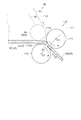
次に、加圧部の構成について説明する。図2は、加圧部の構成を示す概略図である。加圧部110は、堆積部70で堆積したウエブWを最初に加圧する一対の加圧ローラー111,112を有している。そして、一対の加圧ローラー111,112は、上方に位置する加圧ローラーとしての第1加圧ローラー111と下方に位置する加圧ローラーとしての第2加圧ローラー112とにより構成されている。なお、一対の加圧ローラー111,112において上方に位置する加圧ローラーとしての第1加圧ローラー111と下方に位置する加圧ローラーとしての第2加圧ローラー112とを規定する定義は、一対の加圧ローラー111,112で加圧されたウエブWの搬送方向の正面から一対の加圧ローラー111,112を見たときを基準として、相対的に上方に位置する加圧ローラーを第1加圧ローラー111とし、下方に位置する加圧ローラーを第2加圧ローラー112としている。
Next, the configuration of the pressure unit will be described. FIG. 2 is a schematic diagram illustrating a configuration of the pressurizing unit. The
また、加圧部110では、一対の加圧ローラー111,112のうち、第1加圧ローラー111は第2加圧ローラー112よりも、ウエブWの搬送方向の水平成分において下流側に位置するように構成されている。加圧部110の上流側のウエブW1は、加圧部110を通過することで圧縮され、厚みが縮小されたウエブW2となる。そして、本実施形態では、中間搬送部90からほぼ水平方向に搬送されたウエブW1が加圧部110を通過すると、加圧部110は斜めに傾いて配置されているため、ウエブW2の搬送方向は、水平方向から下方側に搬送方向が変化する。このようにウエブWの搬送方向は、加圧部110の上流側と下流側で変化している。そのため、ウエブWの搬送方向の水平成分により、一対の加圧ローラー111,112の位置を規定する。ウエブW1の搬送方向は図2における右方向であり、ウエブW2の搬送方向は図2における右斜め下方向である。そこで、ウエブW1、W2とも搬送方向の水平成分は図2における右方向となり、同じ方向として規定できる。具体的には、第1加圧ローラー111の回転中心軸C1が第2加圧ローラー112の回転中心軸C2よりも、ウエブWの搬送方向の水平成分において下流側に位置している。また、本実施形態では、図2に示すように、第2加圧ローラー112の方が、第1加圧ローラー111よりもウエブWに接するタイミングが早い。すなわち、第2加圧ローラー112におけるウエブWに接する表面112aの方が、第1加圧ローラー111におけるウエブWに接する表面111aよりも、ウエブWの搬送方向の上流側に位置する。
In the
そして、一対の加圧ローラー111,112の回転中心軸C1,C2の方向に加圧ローラー111,112を見た時に、加圧ローラー111,112の中心を通る線L1と鉛直線L2との成す角度θ1は20度以上90度以下である。換言すると、第2加圧ローラー112の回転中心軸C2を通る鉛直線L2に対して、加圧ローラー111,112の各回転中心軸C1,C2を結ぶ線L1が、ウエブWの搬送方向の水平成分において下流側に傾斜する位置に、一対の加圧ローラー111,112が配置されている。
When the
また、このような位置に一対の加圧ローラー111,112が配置されることにより、第2加圧ローラー112の上側に空間領域が形成される。そして、当該空間領域に中間搬送部90の一部を配置することができる。具体的には、第2加圧ローラー112の上側の空間領域に中間搬送部90の下流側の張架ローラー92aを配置する。これにより、中間搬送部90によって搬送ベルト91側に吸引されたウエブWが加圧部110側に搬送した際、加圧部110側に近づいた位置で吸引力が低下し、中間搬送部90側で吸引していたウエブWの一部分が重力方向に落下するが、落下した部分のウエブWは第2加圧ローラー112の鉛直方向上方の表面112aで支持される。従って、中間搬送部90から搬送されるウエブWを確実に搬送させることができる。そして、本実施形態にかかるウエブWに対して加圧する加圧部110では、堆積部70で形成されたウエブW1の厚みに対しておよそ1/5から1/30の厚みのウエブW2に加圧加工される。なお、一対の加圧ローラー111,112はウエブWを最初に加圧する一対のローラーと説明したがこれに限られない。一対の加圧ローラー111,112よりも上流側に、搬送の目的で一対のローラーを有する場合がある。このような搬送ローラーは加圧が目的でないので、搬送ローラーを通過することでの厚みの変化は少ない。本願の一対の加圧ローラー111,112は、ウエブWの厚みを1/5から1/30に変化させるローラーと定義してもよい。
Moreover, a space area | region is formed above the
また、第1加圧ローラー111と第2加圧ローラー112とはお互いに独立して回転する。具体的には、第1加圧ローラー111と第2加圧ローラー112とには駆動源としてのモーターが各々に接続されており、当該各モーターを駆動させることにより、第1加圧ローラー111(図2において時計反対回り方向(矢印方向))と第2加圧ローラー112(図2において時計回り方向(矢印方向))とをそれぞれ回転させることができる。これにより、第1加圧ローラー111または第2加圧ローラー112のウエブWの搬送時における空転が抑制されるため、ウエブWを円滑に搬送させることができる。さらに、この場合、第1加圧ローラー111の回転速度は第2加圧ローラー112の回転速度よりも速くさせることが好ましい。例えば、第1加圧ローラー111の回転速度を第2加圧ローラー112の回転速度に対して0.01%から2%程度速くなるように駆動制御する。これにより、ウエブWが第1加圧ローラー111の回転に追従して、第1加圧ローラー111と第2加圧ローラー112とのニップ部に容易に誘導させることができる。
Further, the
以上、本実施形態によれば、以下の効果を得ることができる。 As described above, according to the present embodiment, the following effects can be obtained.
堆積部70によって堆積されたウエブW(堆積物)は最初に一対の第1加圧ローラー111と第2加圧ローラー112とで加圧される。ここで、下方に配置された第2加圧ローラー112に対して上方に配置された第1加圧ローラー111がウエブW(W1)の搬送方向の下流側に位置している。このため、ウエブW(W1)は下方に向かいながら第1加圧ローラー111と第2加圧ローラー112とによって搬送されるので、搬送されるウエブW(W1)の重力が作用し、第1加圧ローラー111と第2加圧ローラー112とで搬送しやすくなる。また、下方に配置された第2加圧ローラー112の一部でウエブW(W1)が支持されるので、ニップ部入口付近でウエブW(W1)が垂れ下がって滞留して搬送されにくくなることを抑制することができる。
The web W (deposit) deposited by the
さらに、第1加圧ローラー111と第2加圧ローラー112とがそれぞれ独立して回転する。このとき、下方に配置された第2加圧ローラー112の回転速度よりも上方に配置された第1加圧ローラー111の回転速度を速くする。これにより、ウエブW(W1)の重力方向上側の方も確実に搬送され、第1加圧ローラー111の回転に追従し、さらにウエブW(W1)を円滑に搬送させることができる。
Further, the
(第2実施形態)
次に、第2実施形態について説明する。なお、本実施形態にかかるシート製造装置の基本的な構成は第1実施形態にかかるシート製造装置1の構成と同様なので説明は省略し、第1実施形態の構成と異なる構成、すなわち、加圧部の構成ついて主に説明する。
(Second Embodiment)
Next, a second embodiment will be described. Since the basic configuration of the sheet manufacturing apparatus according to the present embodiment is the same as the configuration of the sheet manufacturing apparatus 1 according to the first embodiment, the description thereof is omitted, and a configuration different from the configuration of the first embodiment, that is, pressurization. The configuration of the part will be mainly described.
本実施形態にかかる加圧部110aは、図3に示すように、ウエブWを最初に加圧する一対の加圧ローラー111,112を有し、一対の加圧ローラー111,112のうち、上方に位置する第1加圧ローラー111は下方に位置する第2加圧ローラー112よりも、ウエブWの搬送方向の水平成分において下流側に位置している。さらに、ウエブWが、一対の加圧ローラー111,112に挟持される部分よりもウエブWの搬送方向上流側に、ウエブWを一対の加圧ローラー111,112に誘導するガイド部材300を有している。
As shown in FIG. 3, the
本実施形態のガイド部材300は、ガイドベルト301と、張架ローラー302とを有している。ガイドベルト301は、エンドレスのベルトであり、張架ローラー302と第1加圧ローラー111とで張架されている。そして、第1加圧ローラー111が回転することにより、ガイドベルト301が張架ローラー302及び第1加圧ローラー111に倣って回転移動するように構成されている。
The
そして、第1加圧ローラー111と第2加圧ローラー112とによってニップされるニップ部入口に対応する位置に位置するガイドベルト301の一部がウエブW(W1)をニップ部に誘導する誘導部300aとして機能する。また、一対の加圧ローラー111,112の中心を通る線L1と誘導部300aに対応するガイドベルト301とで成す角度θ2は約90度に設定される。
Then, a guide portion where a part of the
以上、上記実施形態によれば、第1実施形態にかかる効果に加え、以下の効果を得ることができる。 As mentioned above, according to the said embodiment, in addition to the effect concerning 1st Embodiment, the following effects can be acquired.
堆積部70で堆積されたウエブW(W1)は、第1加圧ローラー111と第2加圧ローラー112とで構成されるニップ部のニップ部入口に対応する位置に設けられたガイド部材300の誘導部300aに倣って搬送される。これにより、ニップ部入口においてウエブW(W1)の一部が滞留することなく、ウエブW(W1)を円滑に搬送させることができる。
The web W (W1) accumulated in the
本発明は上述した実施形態に限定されず、上述した実施形態に種々の変更や改良などを加えることが可能である。変形例を以下に述べる。変形例を組み合わせてもよい。 The present invention is not limited to the above-described embodiment, and various modifications and improvements can be added to the above-described embodiment. A modification will be described below. Modifications may be combined.
(変形例1)上記実施形態では、一対の加圧ローラー111,112の中心を通る線L1と鉛直線L2との成す角度θ1が比較的小さい場合について説明したが、これに限定されない。上記角度は90度以下であればよい。図4は、変形例にかかる加圧部の構成を示す概略図である。図4に示すように、加圧部110にかかる一対の加圧ローラー111,112の回転中心軸C1,C2の方向に加圧ローラー111,112を見た時に、加圧ローラー111,112の中心を通る線L1と鉛直線L2との成す角度θ1は約90度である。このようにすれば、ウエブWは下方に向かいながら一対の加圧ローラー111,112によって搬送されるので、搬送されるウエブWの重力も最大限に作用し、一対の加圧ローラー111,112に搬送されやすくなる。さらに、第1加圧ローラー111と第2加圧ローラー112とがほぼ水平方向に並列して配置されることにより、第2加圧ローラー112の上側により広い空間領域が形成される。そして、第2加圧ローラー112の上側の空間領域に中間搬送部90の下流側の張架ローラー92aをより第1加圧ローラー111側に配置させることができる。これにより、中間搬送部90によって搬送ベルト91側に吸引されたウエブWが加圧部110側に搬送した際、加圧部110側に近づいた位置で吸引力が低下し、中間搬送部90側で吸引していたウエブWの一部分が重力方向に落下した際、より広い範囲で落下した部分のウエブWを支持することができる。なお、図4において、ウエブW2の搬送方向はほぼ鉛直方向なため、水平成分はないことになる。このような場合は、ウエブW1の搬送方向の水平成分を用いて、第1加圧ローラー111の方が下流側にあると規定される。
(Modification 1) In the above embodiment, the case where the angle θ1 formed by the line L1 passing through the centers of the pair of
(変形例2)上記第2実施形態では、ガイドベルト301を備えたガイド部材300を備えたが、この構成に限定されない。ウエブW(W1)を誘導する単なるガイドで構成されるものであってもよい。図5は、他の変形例にかかる加圧部の構成を示す概略図である。図5に示すように、ガイド部材400は、一対の加圧ローラー111,112に挟持される部分よりもウエブWの搬送方向上流側に配置されたガイド401を有している。ガイド401は、ニップ部入口に対応する位置に配置され、搬送されるウエブW(W1)をニップ部に誘導する誘導面を有する誘導部401aを備えている。このようにしても、堆積部70で堆積されたウエブW(W1)は、第1加圧ローラー111と第2加圧ローラー112とで構成されるニップ部のニップ部入口に対応する位置に設けられたガイド部材400のガイド401の誘導部401aに倣って搬送される。これにより、ニップ部入口においてウエブW(W1)の一部が滞留することなく、ウエブW(W1)を円滑に搬送させることができる。
(Modification 2) In the second embodiment, the
(変形例3)上記実施形態では、加圧部110の第1加圧ローラー111の回転速度を第2加圧ローラー112の回転速度よりも速くさせたが、この構成に限定されない。例えば、第1加圧ローラー111の摩擦係数が第2加圧ローラー112の摩擦係数よりも大きくなるように構成してもよい。具体的には、第2加圧ローラー112に金属材料を用い、第2加圧ローラー112の表面部を、例えば、ハードクロムメッキや無電解ニッケルメッキを施し、第1加圧ローラー111には弾性材としてコットン材やゴム材等を用いる。また、ゴム材としては、ウレタンゴム、シリコーンゴム、EPDM(エチレンプロピレンジエンゴム)等を用いる。このようにしても、第1加圧ローラー111の表面と第2加圧ローラー112の表面とで生じる摩擦係数差により、第1加圧ローラー111と第2加圧ローラー112とによるニップ部に均一にウエブWを搬送させることができる。
(Modification 3) In the said embodiment, although the rotational speed of the
(変形例4)上記実施形態では、堆積部70で堆積されたウエブWを最初に加圧する一対の加圧ローラー111,112の構成について説明したが、一対の加圧ローラー111,112の搬送方向の下流側に設けられた他の一対の加圧ローラーにおいても、一対の加圧ローラー111,112と同様の構成であってもよい。すなわち、一対の加圧ローラー111,112の搬送方向に下流側に設けられた他の一対の加圧ローラーにおいても、一対の加圧ローラーのうち、上方に位置する加圧ローラーは下方に位置する加圧ローラーよりも、ウエブW(W2)の搬送方向の水平成分において下流側に位置するように構成する。このようにすれば、一対の加圧ローラー111,112によって搬送されたウエブW(W2)の搬送を円滑に搬送させることができる。
(Modification 4) In the above embodiment, the configuration of the pair of
(変形例5)上記実施形態では、加圧部110と加熱部120とを別個に配置したが、この構成に限定されない。加圧部110の第1加圧ローラー111と第2加圧ローラー112の少なくとも一方を加熱。してもよい。加圧部110は、加圧することができれば加熱してもしなくてもよい。このようにすれば、装置構成を簡略化させることができる。
(Modification 5) In the said embodiment, although the
(変形例6)上記実施形態では、第1加圧ローラー111と第2加圧ローラー112とのローラー径を同じとしたが、この構成に限定されない。第1加圧ローラー111の径と第2加圧ローラー112の径とを異ならせ、適宜設定してもよい。このようにすれば、装置レイアウトの自由度を高めることができる。
(Modification 6) In the said embodiment, although the roller diameter of the
(変形例7)上記実施形態では、メッシュベルト73上に成形されたウエブWを吸引しながら搬送する中間搬送部90を備えたが、この構成に限定されない。例えば、中間搬送部90に替えてスクレイパーを配置してもよい。このようにしても、スクレイパーによってメッシュベルト73上に成形されたウエブWを剥離しながら加圧部110に搬送することができる。また、装置構成も簡易化される。
(Modification 7) In the above embodiment, the
(変形例8)上記実施形態では、第1加圧ローラー111と第2加圧ローラー112とが別個に回転するように構成したが、この構成に限定されない。第1加圧ローラー111及び第2加圧ローラー112のうち、一方のローラーを駆動回転させる駆動ローラーとし、他方のローラーをウエブWを介して従動する従動ローラーとしてもよい。このようにしても、一対の加圧ローラーのうち、上方に位置する加圧ローラーは下方に位置する加圧ローラーよりも、ウエブWの搬送方向の水平成分において下流側に位置することにより、上記同様の効果を得ることができる。
(Modification 8) In the said embodiment, although comprised so that the
1…シート製造装置、10…供給部、20…粗砕部、30…解繊部、40…分級部、40a…導入口、40b…下部取出口、40c…上部排気口、41…筒部、42…円錐部、50…選別部、60…添加物投入部、70…堆積部、90…中間搬送部、110…加圧部、110a…加圧部、111…上方に位置する加圧ローラーとしての第1加圧ローラー、112…下方に位置する加圧ローラーとしての第2加圧ローラー、120…加熱部、130…切断部、160…スタッカー、300,400…ガイド部材。 DESCRIPTION OF SYMBOLS 1 ... Sheet manufacturing apparatus, 10 ... Supply part, 20 ... Crushing part, 30 ... Defibration part, 40 ... Classification part, 40a ... Inlet port, 40b ... Lower outlet, 40c ... Upper exhaust port, 41 ... Tube part, 42 ... conical part, 50 ... sorting part, 60 ... additive addition part, 70 ... deposition part, 90 ... intermediate transport part, 110 ... pressurizing part, 110a ... pressurizing part, 111 ... as a pressure roller located above 1st pressure roller, 112 ... 2nd pressure roller as a pressure roller located below, 120 ... heating part, 130 ... cutting part, 160 ... stacker, 300, 400 ... guide member.
Claims (6)
前記堆積物を加圧する加圧部と、
を備え、
前記加圧部は、前記堆積物を加圧する一対の加圧ローラーを有し、
前記一対の加圧ローラーのうち、鉛直方向の上方に位置する第1加圧ローラーは、前記堆積物の搬送方向において、前記鉛直方向の下方に位置する第2加圧ローラーよりも下流側に位置し、
前記搬送部は前記堆積物を上方に吸引して側方に搬送し、搬送後に落下した前記堆積物が前記第2加圧ローラーの上で支持されることを特徴とするシート製造装置。 A transport unit for transporting a deposit containing fibers to a pressurizing unit;
A pressurizing unit for pressurizing the deposit;
With
The pressure unit has a pair of pressure rollers that pressurize the deposit,
Of the pair of pressure rollers, the first pressure roller located above the vertical direction, in the conveying direction of the deposit, on the downstream side of the second pressure roller you positioned below the vertical direction position and,
The transport unit transports laterally by sucking the sediment upwards, supported the deposits that have fallen after conveyed over the second pressure roller sheet manufacturing apparatus according to claim Rukoto.
前記一対の加圧ローラーの回転中心軸の方向に前記一対の加圧ローラーを見た時に、前記第1加圧ローラーと前記第2加圧ローラーの中心を通る線と前記鉛直方向との成す角度は20度以上90度以下であることを特徴とするシート製造装置。 In the sheet manufacturing apparatus according to claim 1,
The angle formed by the line passing through the center of the first pressure roller and the second pressure roller and the vertical direction when the pair of pressure rollers is viewed in the direction of the rotation center axis of the pair of pressure rollers. Is 20 degrees or more and 90 degrees or less, The sheet manufacturing apparatus characterized by the above-mentioned.
前記一対の加圧ローラーは別々の駆動源により互いに独立して回転することを特徴とするシート製造装置。 In the sheet manufacturing apparatus according to claim 1 or 2,
The pair of pressure rollers rotate independently of each other by separate driving sources .
前記第1加圧ローラーの回転速度は前記第2加圧ローラーの回転速度よりも速いことを特徴とするシート製造装置。 In the sheet manufacturing apparatus according to claim 3,
The sheet manufacturing apparatus according to claim 1, wherein a rotation speed of the first pressure roller is higher than a rotation speed of the second pressure roller.
前記第1加圧ローラーの摩擦係数は前記第2加圧ローラーの摩擦係数よりも大きいことを特徴とするシート製造装置。 In the sheet manufacturing apparatus according to claim 3,
The sheet manufacturing apparatus according to claim 1, wherein a friction coefficient of the first pressure roller is larger than a friction coefficient of the second pressure roller.
前記堆積物が前記一対の加圧ローラーに挟持される部分よりも前記堆積物の搬送方向上流側に、前記堆積物を前記一対の加圧ローラーに誘導するガイド部材を有することを特徴とするシート製造装置。
In the sheet manufacturing apparatus according to any one of claims 1 to 5,
A sheet having a guide member that guides the deposit to the pair of pressure rollers on the upstream side in the conveyance direction of the deposit from a portion where the deposit is sandwiched between the pair of pressure rollers. manufacturing device.
Priority Applications (2)
| Application Number | Priority Date | Filing Date | Title |
|---|---|---|---|
| JP2014194909A JP6439347B2 (en) | 2014-09-25 | 2014-09-25 | Sheet manufacturing equipment |
| US14/861,599 US10626555B2 (en) | 2014-09-25 | 2015-09-22 | Sheet manufacturing apparatus |
Applications Claiming Priority (1)
| Application Number | Priority Date | Filing Date | Title |
|---|---|---|---|
| JP2014194909A JP6439347B2 (en) | 2014-09-25 | 2014-09-25 | Sheet manufacturing equipment |
Publications (3)
| Publication Number | Publication Date |
|---|---|
| JP2016065338A JP2016065338A (en) | 2016-04-28 |
| JP2016065338A5 JP2016065338A5 (en) | 2017-09-28 |
| JP6439347B2 true JP6439347B2 (en) | 2018-12-19 |
Family
ID=55583813
Family Applications (1)
| Application Number | Title | Priority Date | Filing Date |
|---|---|---|---|
| JP2014194909A Active JP6439347B2 (en) | 2014-09-25 | 2014-09-25 | Sheet manufacturing equipment |
Country Status (2)
| Country | Link |
|---|---|
| US (1) | US10626555B2 (en) |
| JP (1) | JP6439347B2 (en) |
Families Citing this family (1)
| Publication number | Priority date | Publication date | Assignee | Title |
|---|---|---|---|---|
| JP2022052117A (en) * | 2020-09-23 | 2022-04-04 | セイコーエプソン株式会社 | Fiber structure and production apparatus of fiber structure |
Family Cites Families (17)
| Publication number | Priority date | Publication date | Assignee | Title |
|---|---|---|---|---|
| US5422710A (en) * | 1992-02-14 | 1995-06-06 | Mita Industrial Co., Ltd. | Sheet discharging device for use in an image forming apparatus |
| US5641374A (en) * | 1995-03-16 | 1997-06-24 | Minnesota Mining And Manufacturing Company | Apparatus and method for preventing defects during the lamination of materials |
| DE19934875A1 (en) * | 1999-07-24 | 2001-01-25 | Voith Paper Patent Gmbh | Paper machine |
| US6782637B2 (en) * | 2001-10-30 | 2004-08-31 | Weyerhaeuser Company | System for making dried singulated crosslinked cellulose pulp fibers |
| JP5097463B2 (en) * | 2007-07-23 | 2012-12-12 | メッツォ ペーパー インコーポレイテッド | Paper or paperboard manufacturing apparatus and manufacturing method using the same |
| JP2010150707A (en) * | 2008-12-25 | 2010-07-08 | Marusumi Paper Co Ltd | Method for making paper |
| JP5720255B2 (en) * | 2011-01-12 | 2015-05-20 | セイコーエプソン株式会社 | Paper recycling apparatus and paper recycling method |
| US8882965B2 (en) * | 2011-01-12 | 2014-11-11 | Seiko Epson Corporation | Paper recycling system and paper recycling method |
| JP6213284B2 (en) * | 2013-03-27 | 2017-10-18 | セイコーエプソン株式会社 | Sheet manufacturing equipment |
| JP2014208924A (en) * | 2013-03-27 | 2014-11-06 | セイコーエプソン株式会社 | Sheet manufacturing apparatus |
| JP2014208923A (en) * | 2013-03-27 | 2014-11-06 | セイコーエプソン株式会社 | Sheet manufacturing apparatus |
| JP2014208925A (en) * | 2013-03-27 | 2014-11-06 | セイコーエプソン株式会社 | Sheet manufacturing apparatus |
| JP6263933B2 (en) * | 2013-10-03 | 2018-01-24 | セイコーエプソン株式会社 | Sheet manufacturing equipment |
| JP6277654B2 (en) * | 2013-10-03 | 2018-02-14 | セイコーエプソン株式会社 | Sheet manufacturing equipment |
| JP6149662B2 (en) * | 2013-10-03 | 2017-06-21 | セイコーエプソン株式会社 | Sheet manufacturing apparatus and sheet manufacturing method |
| JP6127901B2 (en) * | 2013-10-21 | 2017-05-17 | セイコーエプソン株式会社 | Sheet manufacturing apparatus and sheet manufacturing method |
| JP2015150707A (en) | 2014-02-10 | 2015-08-24 | キヤノン株式会社 | Information processor, information processing method and program |
-
2014
- 2014-09-25 JP JP2014194909A patent/JP6439347B2/en active Active
-
2015
- 2015-09-22 US US14/861,599 patent/US10626555B2/en active Active
Also Published As
| Publication number | Publication date |
|---|---|
| US10626555B2 (en) | 2020-04-21 |
| US20160090690A1 (en) | 2016-03-31 |
| JP2016065338A (en) | 2016-04-28 |
Similar Documents
| Publication | Publication Date | Title |
|---|---|---|
| JP6492576B2 (en) | Sheet manufacturing equipment | |
| JP6287365B2 (en) | Sheet manufacturing equipment | |
| JP6354154B2 (en) | Sheet manufacturing equipment | |
| JP6357767B2 (en) | Sheet manufacturing equipment | |
| CN105735027B (en) | Sheet manufacturing apparatus and sheet manufacturing method | |
| JP2016098470A (en) | Sheet manufacturing apparatus | |
| WO2016072063A1 (en) | Sheet manufacturing apparatus and method for manufacturing sheet | |
| JP6464758B2 (en) | Sheet manufacturing equipment | |
| JP2016075006A (en) | Sheet production apparatus | |
| JP2018044277A (en) | Sheet production apparatus | |
| JP6417591B2 (en) | Sheet manufacturing apparatus and sheet manufacturing method | |
| JP6340881B2 (en) | Sheet manufacturing equipment | |
| JP6252234B2 (en) | Sheet manufacturing equipment | |
| JP6439347B2 (en) | Sheet manufacturing equipment | |
| JP6248615B2 (en) | Sheet manufacturing equipment | |
| JP2016113735A (en) | Apparatus for manufacturing sheet | |
| JP6418309B2 (en) | Sheet manufacturing equipment | |
| JP2016168678A (en) | Sheet production apparatus and sheet production method | |
| JP2016049662A (en) | Sheet manufacturing apparatus and sheet manufacturing method | |
| JP6464717B2 (en) | Sheet manufacturing apparatus and sheet manufacturing method | |
| JP6269166B2 (en) | Sheet manufacturing equipment | |
| JP2015120132A (en) | Sheet manufacturing apparatus | |
| JP6248616B2 (en) | Sheet manufacturing equipment | |
| JP2016098471A (en) | Sheet manufacturing apparatus and sheet manufacturing method | |
| JP6277831B2 (en) | Sheet manufacturing equipment |
Legal Events
| Date | Code | Title | Description |
|---|---|---|---|
| RD03 | Notification of appointment of power of attorney |
Free format text: JAPANESE INTERMEDIATE CODE: A7423 Effective date: 20160623 |
|
| A521 | Written amendment |
Free format text: JAPANESE INTERMEDIATE CODE: A523 Effective date: 20170818 |
|
| A621 | Written request for application examination |
Free format text: JAPANESE INTERMEDIATE CODE: A621 Effective date: 20170818 |
|
| A977 | Report on retrieval |
Free format text: JAPANESE INTERMEDIATE CODE: A971007 Effective date: 20180426 |
|
| A131 | Notification of reasons for refusal |
Free format text: JAPANESE INTERMEDIATE CODE: A131 Effective date: 20180515 |
|
| A521 | Written amendment |
Free format text: JAPANESE INTERMEDIATE CODE: A523 Effective date: 20180705 |
|
| A131 | Notification of reasons for refusal |
Free format text: JAPANESE INTERMEDIATE CODE: A131 Effective date: 20180817 |
|
| RD02 | Notification of acceptance of power of attorney |
Free format text: JAPANESE INTERMEDIATE CODE: A7422 Effective date: 20180914 |
|
| A521 | Written amendment |
Free format text: JAPANESE INTERMEDIATE CODE: A523 Effective date: 20181011 |
|
| TRDD | Decision of grant or rejection written | ||
| A01 | Written decision to grant a patent or to grant a registration (utility model) |
Free format text: JAPANESE INTERMEDIATE CODE: A01 Effective date: 20181023 |
|
| A61 | First payment of annual fees (during grant procedure) |
Free format text: JAPANESE INTERMEDIATE CODE: A61 Effective date: 20181105 |
|
| R150 | Certificate of patent or registration of utility model |
Ref document number: 6439347 Country of ref document: JP Free format text: JAPANESE INTERMEDIATE CODE: R150 |