JP6248616B2 - Sheet manufacturing equipment - Google Patents

Sheet manufacturing equipment Download PDF

Info

Publication number
JP6248616B2
JP6248616B2 JP2013266613A JP2013266613A JP6248616B2 JP 6248616 B2 JP6248616 B2 JP 6248616B2 JP 2013266613 A JP2013266613 A JP 2013266613A JP 2013266613 A JP2013266613 A JP 2013266613A JP 6248616 B2 JP6248616 B2 JP 6248616B2
Authority
JP
Japan
Prior art keywords
unit
manufacturing apparatus
sheet manufacturing
drum
fixing member
Prior art date
Legal status (The legal status is an assumption and is not a legal conclusion. Google has not performed a legal analysis and makes no representation as to the accuracy of the status listed.)
Active
Application number
JP2013266613A
Other languages
Japanese (ja)
Other versions
JP2015120317A5 (en
JP2015120317A (en
Inventor
中村 昌英
昌英 中村
Current Assignee (The listed assignees may be inaccurate. Google has not performed a legal analysis and makes no representation or warranty as to the accuracy of the list.)
Seiko Epson Corp
Original Assignee
Seiko Epson Corp
Priority date (The priority date is an assumption and is not a legal conclusion. Google has not performed a legal analysis and makes no representation as to the accuracy of the date listed.)
Filing date
Publication date
Application filed by Seiko Epson Corp filed Critical Seiko Epson Corp
Priority to JP2013266613A priority Critical patent/JP6248616B2/en
Priority to US14/569,930 priority patent/US9255360B2/en
Publication of JP2015120317A publication Critical patent/JP2015120317A/en
Publication of JP2015120317A5 publication Critical patent/JP2015120317A5/ja
Application granted granted Critical
Publication of JP6248616B2 publication Critical patent/JP6248616B2/en
Active legal-status Critical Current
Anticipated expiration legal-status Critical

Links

Images

Description

本発明は、シート製造装置に関する。   The present invention relates to a sheet manufacturing apparatus.

従来、紙を粉砕して解繊する乾式解繊部と、乾式解繊部で解繊された解繊物を搬送する第1搬送部と、第1搬送部で搬送された解繊物を気流分級して脱墨する分級部と、分級部で脱墨された解繊物を搬送する第2搬送部と、第2搬送部で搬送された解繊物で紙を成形する紙成形部と、を有する紙再生装置が知られている。そして、紙成形部のフォーミングドラムの内部には回転可能なニードルロールが配置されている(例えば、特許文献1参照)。   Conventionally, a dry defibrating unit that pulverizes and defibrates paper, a first transport unit that transports the defibrated material that has been defibrated by the dry defibrating unit, and an air flow through the defibrated material transported by the first transport unit A classification unit for classifying and deinking; a second conveyance unit for conveying the defibrated material deinked by the classification unit; and a paper molding unit for forming paper with the defibrated material conveyed by the second conveyance unit; There is known a paper recycling apparatus having A rotatable needle roll is disposed inside the forming drum of the paper forming unit (see, for example, Patent Document 1).

特開2012−144819号公報JP 2012-144819 A

しかしながら、上記装置では、回転するニードルロールに繊維を含む材料等が付着したり、絡まったりするため、篩機能の効率が低下してしまう、という課題があった。   However, the above-described apparatus has a problem that the efficiency of the sieving function is reduced because a material containing fibers is attached to or entangled with the rotating needle roll.

本発明は、上述の課題の少なくとも一部を解決するためになされたものであり、以下の形態または適用例として実現することが可能である。   SUMMARY An advantage of some aspects of the invention is to solve at least a part of the problems described above, and the invention can be implemented as the following forms or application examples.

[適用例1]本適用例にかかるシート製造装置は、繊維を含む材料を複数の開口を通過させる選別部と、前記開口を通過した前記材料を用いてシートを成形する成形部と、を備えるシート製造装置であって、前記選別部は、円筒面に前記複数の開口を有し回転中心軸回りに回転する円筒部と、前記円筒部内において、前記回転中心軸よりも鉛直方向における上側に離間して配置され、前記円筒部とは離間し、回転せずに固定されている固定部材と、を有することを特徴とする。   Application Example 1 A sheet manufacturing apparatus according to this application example includes a selection unit that allows a material containing fibers to pass through a plurality of openings, and a forming unit that forms a sheet using the material that has passed through the openings. In the sheet manufacturing apparatus, the sorting unit has a plurality of openings on a cylindrical surface and rotates around a rotation center axis, and is separated from the rotation center axis in the vertical direction within the cylinder unit. And a fixing member that is spaced from the cylindrical portion and fixed without rotating.

この構成によれば、選別部の円筒部を回転中心軸回りに回転させると、円筒部の回転に伴って円筒部内の材料も円筒部の回転方向に回転する。また、材料は遠心力により円筒部の内壁側に押し圧され、内壁面に材料が張り付いた状態で回転移動する。ここで、円筒部内における円筒部の回転中心軸よりも鉛直方向における上側に離間した位置には固定部材が配置されている。固定部材は円筒部とは離間し、回転せずに固定されている。従って、内壁面に材料が張り付いた状態で回転移動する材料は、円筒部と固定部材の隙間を通過する際に固定部材に接触する。そして、接触した材料は、円筒部の内壁側から剥がれ落ち、剥がれ落ちた材料は、再度回転移動される。これにより、篩機能の効率を向上させることができる。また、円筒部の内壁に張り付いた材料を剥がすことで、複数の開口を露出させることができ、材料が開口を通過しやすくなる。   According to this configuration, when the cylindrical portion of the sorting portion is rotated around the rotation center axis, the material in the cylindrical portion is also rotated in the rotation direction of the cylindrical portion as the cylindrical portion is rotated. Further, the material is pressed against the inner wall side of the cylindrical portion by centrifugal force, and rotates and moves in a state where the material sticks to the inner wall surface. Here, a fixing member is arranged at a position separated in the vertical direction above the rotation center axis of the cylindrical portion in the cylindrical portion. The fixing member is separated from the cylindrical portion and fixed without rotating. Therefore, the material that rotates while the material is stuck to the inner wall surface contacts the fixing member when passing through the gap between the cylindrical portion and the fixing member. The contacted material is peeled off from the inner wall side of the cylindrical portion, and the peeled material is rotated and moved again. Thereby, the efficiency of a sieving function can be improved. Further, by peeling the material stuck to the inner wall of the cylindrical portion, a plurality of openings can be exposed, and the material can easily pass through the openings.

[適用例2]上記適用例にかかるシート製造装置の前記固定部材は前記材料と接触可能であり、前記材料と接触する部分が面状であることを特徴とする。   Application Example 2 In the sheet manufacturing apparatus according to the application example, the fixing member can contact the material, and a portion in contact with the material is planar.

この構成によれば、固定部材における繊維を含む材料と接触する部分が面状なので、繊維が絡むことがない。これにより、篩機能の効率をさらに向上させることができる。   According to this structure, since the part which contacts the material containing the fiber in a fixing member is planar, a fiber does not get entangled. Thereby, the efficiency of a sieve function can further be improved.

[適用例3]上記適用例にかかるシート製造装置の前記固定部材は、断面が四角い板状部材であることを特徴とする。   Application Example 3 The fixing member of the sheet manufacturing apparatus according to the application example is a plate member having a square cross section.

この構成によれば、板状部材にすることで製造が容易で、回転により材料が衝突しても耐久性がよい。   According to this structure, it is easy to manufacture by using a plate-like member, and durability is good even if a material collides by rotation.

[適用例4]上記適用例にかかるシート製造装置は、前記円筒部における前記回転中心軸の延接方向に離間して両端に備えられ、回転しない2つの側部を有し、前記固定部材は前記2つの側部に固定されることを特徴とする。   Application Example 4 The sheet manufacturing apparatus according to the application example includes two side portions that are provided at both ends of the cylindrical portion so as to be spaced apart from each other in the extending direction of the rotation center shaft, and the fixing member is It is fixed to the two side portions.

この構成によれば、固定部材は回転しない側部に固定される。これにより、回転する円筒部の内部に容易に固定部材を固定配置することができる。   According to this structure, a fixing member is fixed to the side part which does not rotate. Thereby, a fixing member can be easily fixedly arranged inside the rotating cylindrical portion.

[適用例5]上記適用例にかかるシート製造装置の前記固定部材は、仮想鉛直面に対して傾斜していることを特徴とする。   Application Example 5 In the sheet manufacturing apparatus according to the application example, the fixing member is inclined with respect to a virtual vertical plane.

この構成によれば、固定部材は傾斜しているため、材料が固定部材に衝突した際の衝撃を緩和させることができる。   According to this configuration, since the fixing member is inclined, the impact when the material collides with the fixing member can be reduced.

[適用例6]上記適用例にかかるシート製造装置は、前記回転中心軸は水平方向に配置され、前記回転中心軸を通る仮想水平面よりも前記円筒部内の上側における回転方向において、前記回転中心軸を通る仮想鉛直面よりも下流側に前記固定部材を有することを特徴とする。   Application Example 6 In the sheet manufacturing apparatus according to the application example described above, the rotation center axis is disposed in a horizontal direction, and the rotation center axis in the rotation direction on the upper side in the cylindrical portion with respect to a virtual horizontal plane passing through the rotation center axis. The fixing member is provided on the downstream side of a virtual vertical plane that passes through.

この構成によれば、固定部材は、回転軸方向より上方、かつ、回転中心軸を通る仮想鉛直面よりも下流側に配置される。このため、円筒部の上方において円筒部の内壁に張り付いた材料が剥がされて下方側に落下することにより、開口から通過しやすくすることができる。   According to this configuration, the fixing member is disposed above the rotation axis direction and downstream of the virtual vertical plane passing through the rotation center axis. For this reason, when the material stuck to the inner wall of the cylindrical portion is peeled off above the cylindrical portion and falls downward, the material can easily pass through the opening.

[適用例7]上記適用例にかかるシート製造装置は、前記円筒部の内周面に凹凸を有することを特徴とする。   Application Example 7 The sheet manufacturing apparatus according to the application example described above is characterized in that the inner peripheral surface of the cylindrical portion has irregularities.

この構成によれば、凹凸により材料が円筒部とともに移動しやすくなり、さらに、篩の機能効率を高めることができる。   According to this structure, it becomes easy for a material to move with a cylindrical part by unevenness | corrugation, and also the functional efficiency of a sieve can be improved.

シート製造装置の構成を示す概略図。Schematic which shows the structure of a sheet manufacturing apparatus. 分級部及び選別部の構成を示す詳細図。Detailed drawing which shows the structure of a classification | category part and a selection part. ドラム部の構成を示す概略図。Schematic which shows the structure of a drum part. 選別部の構成を示す概略図。Schematic which shows the structure of a selection part. 選別部の構成を示す概略図。Schematic which shows the structure of a selection part. 選別部の構成を示す概略図。Schematic which shows the structure of a selection part. シート製造装置の動作方法を示す説明図。Explanatory drawing which shows the operation | movement method of a sheet manufacturing apparatus. 変形例にかかる分級部及び選別部の構成を示す詳細図。FIG. 5 is a detailed view showing the configuration of a classification unit and a selection unit according to a modification. 変形例にかかる分級部の構成を示す概略部。The schematic part which shows the structure of the classification part concerning a modification.

以下、本発明の実施形態について、図面を参照して説明する。なお、以下の各図においては、各部材等を認識可能な程度の大きさにするため、各部材等の尺度を実際とは異ならせて示している。また、鉛直方向における上方、下方や上側、下側は鉛直方向に沿う方向における上方、下方や上側、下側を示す。なお、鉛直方向における上方は鉛直方向と逆方向である。単に上方、下方や上側、下側という記載の場合も鉛直方向における上方、下方や上側、下側を示す。   Hereinafter, embodiments of the present invention will be described with reference to the drawings. In the following drawings, the scale of each member or the like is shown differently from the actual scale so as to make each member or the like recognizable. Further, the upper, lower, upper, and lower sides in the vertical direction indicate the upper, lower, upper, and lower sides in the direction along the vertical direction. Note that the upper direction in the vertical direction is opposite to the vertical direction. In the case of simply “upper”, “lower”, “upper”, and “lower”, the upper, lower, upper, and lower sides in the vertical direction are also indicated.

まず、シート製造装置の構成について説明する。シート製造装置は、例えば、純パルプシートや古紙などの原料(被解繊物)Puを新たなシートPrに成形する技術に基づくものである。シート製造装置は、繊維を含む材料を複数の開口を通過させる選別部と、開口を通過した材料を用いてシートを成形する成形部と、を備え、選別部は、円筒面に複数の開口を有し回転中心軸回りに回転する円筒部と、円筒部内において、回転中心軸よりも鉛直方向における上側に離間して配置され、前記円筒部とは離間し、回転せずに固定されている固定部材と、を有するものである。以下、具体的にシート製造装置の構成について説明する。   First, the configuration of the sheet manufacturing apparatus will be described. The sheet manufacturing apparatus is based on a technique for forming a raw material (defibrated material) Pu such as a pure pulp sheet or used paper into a new sheet Pr, for example. The sheet manufacturing apparatus includes a sorting unit that allows a material containing fibers to pass through a plurality of openings, and a forming unit that forms a sheet using the material that has passed through the openings. The sorting unit has a plurality of openings on a cylindrical surface. A cylindrical portion that rotates around the rotation center axis, and is arranged in the cylinder portion so as to be spaced apart from the rotation center axis in the vertical direction and is spaced apart from the cylindrical portion and fixed without rotating. And a member. Hereinafter, the configuration of the sheet manufacturing apparatus will be specifically described.

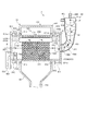
図1は、本実施形態にかかるシート製造装置の構成を示す概略図である。図1に示すように、本実施形態のシート製造装置1は、供給部10と、粗砕部20と、解繊部30と、分級部40と、選別部50と、添加物投入部60と、分散部70と、搬送部100と、切断部110及び成形部200等を備えている。そして、これらの部材を制御する制御部を備えている。   FIG. 1 is a schematic diagram illustrating a configuration of a sheet manufacturing apparatus according to the present embodiment. As shown in FIG. 1, the sheet manufacturing apparatus 1 of the present embodiment includes a supply unit 10, a crushing unit 20, a defibrating unit 30, a classification unit 40, a sorting unit 50, and an additive charging unit 60. , A dispersion unit 70, a transport unit 100, a cutting unit 110, a molding unit 200, and the like. And the control part which controls these members is provided.

供給部10は、粗砕部20に古紙Puを供給するものである。供給部10は、例えば、複数枚の古紙Puを重ねて貯めておくトレー11と、トレー11中の古紙Puを粗砕部20に連続して投入可能な自動送り機構12等を備えている。シート製造装置1に供給する古紙Puとしては、例えば、オフィスで現在主流となっているA4サイズの用紙等である。   The supply unit 10 supplies the used paper Pu to the crushing unit 20. The supply unit 10 includes, for example, a tray 11 that accumulates and stores a plurality of used paper Pu, and an automatic feeding mechanism 12 that can continuously input the used paper Pu in the tray 11 to the crushing unit 20. The used paper Pu supplied to the sheet manufacturing apparatus 1 is, for example, A4 size paper that is currently mainstream in offices.

粗砕部20は、供給された古紙Puを数センチメートル角の紙片に裁断するものである。粗砕部20では、粗砕刃21を備え、通常のシュレッダーの刃の切断幅を広げたような装置を構成している。これにより、供給された古紙Puを容易に紙片に裁断することができる。そして、分断された粗砕紙は、配管201を介して解繊部30に供給される。   The crushing unit 20 cuts the supplied used paper Pu into pieces of several centimeters square. The crushing unit 20 includes a crushing blade 21 and constitutes an apparatus in which the cutting width of a normal shredder blade is widened. Thereby, the supplied used paper Pu can be easily cut into pieces of paper. Then, the divided coarsely crushed paper is supplied to the defibrating unit 30 via the pipe 201.

解繊部30は、回転する回転刃(図示せず)を備え、粗砕部20から供給された粗砕紙を繊維状に解きほぐす解繊を行うものである。なお、本実施形態の解繊部30は、空気中で乾式で解繊を行うものである。解繊部30の解繊処理により、印刷されたインクやトナー、にじみ防止材等の紙への塗工材料等は、数十μm以下の粒(以下、「インク粒」という)となって繊維と分離する。従って、解繊部30から出る解繊物は、紙片の解繊により得られる繊維とインク粒である。そして、回転刃の回転によって気流が発生する機構となっており、配管202を介して解繊された繊維はこの気流に乗って分級部40に搬送される。なお、風発生機構を備えていない乾式の解繊部30を用いる場合には、粗砕部20から解繊部30に向けて気流を発生させる気流発生装置を別途設けるようにすればよい。   The defibrating unit 30 includes a rotating blade (not shown) that rotates, and performs defibrating to unravel the crushed paper supplied from the crushing unit 20 into fibers. In addition, the defibrating unit 30 of the present embodiment performs defibrating in a dry manner in the air. As a result of the defibrating process of the defibrating unit 30, the printed ink, toner, and the material applied to the paper such as the anti-bleeding material become fibers of several tens of μm or less (hereinafter referred to as “ink particles”). And separate. Therefore, the defibrated material that comes out from the defibrating unit 30 is fibers and ink particles obtained by defibrating a piece of paper. Then, the airflow is generated by the rotation of the rotary blade, and the fiber defibrated via the pipe 202 is carried on the airflow and conveyed to the classifying unit 40. In addition, when using the dry type defibrating part 30 which is not equipped with a wind generation mechanism, what is necessary is just to provide separately the airflow generator which generates an airflow from the crushing part 20 toward the defibrating part 30. FIG.

分級部40は、導入された導入物を気流により分級するものである。本実施形態では、導入物としての解繊物をインク粒と繊維とに分級する。分級部40は、例えば、サイクロンを適用することにより、搬送された繊維をインク粒と脱墨繊維(脱墨解繊物)とに気流分級することができる。なお、サイクロンに替えて他の種類の気流式分級器を利用してもよい。この場合、サイクロン以外の気流式分級器としては、例えば、エルボージェットやエディクラシファイヤー等が用いられる。気流式分級器は旋回気流を発生させ、解繊物のサイズと密度により受ける遠心力の差によって分離、分級するもので、気流の速度、遠心力の調整により、分級点を調整することができる。これにより比較的小さく密度の低いインク粒と、インク粒より大きく密度の高い繊維とに分けられる。繊維からインク粒を除去することを脱墨と言う。   The classifying unit 40 classifies the introduced material by airflow. In this embodiment, the defibrated material as the introduced material is classified into ink particles and fibers. The classification unit 40 can classify the conveyed fibers into ink particles and deinked fibers (deinked defibrated material), for example, by applying a cyclone. Note that other types of airflow classifiers may be used instead of the cyclone. In this case, as an airflow classifier other than the cyclone, for example, an elbow jet or an eddy classifier is used. The airflow classifier generates a swirling airflow, which is separated and classified by the difference in centrifugal force received depending on the size and density of the defibrated material, and the classification point can be adjusted by adjusting the speed and centrifugal force of the airflow. . As a result, the ink particles are divided into relatively small and low density ink particles and fibers larger than the ink particles and high density. Removing ink particles from fibers is called deinking.

本実施形態の分級部40は、解繊部30から導入される導入口40aと、導入口40aが接線方向についた筒部41と、筒部41の下部に続く円錐部42と、円錐部42の下部に設けられる下部取出口40bと、筒部41の上部中央に設けられる微粉排出のための上部排気口40cとから構成される。円錐部42は鉛直方向における下方に向かって径が小さくなる。   The classifying unit 40 of the present embodiment includes an introduction port 40a introduced from the defibrating unit 30, a cylinder part 41 with the introduction port 40a attached in a tangential direction, a conical part 42 following the lower part of the cylinder part 41, and a conical part 42. The lower outlet 40b provided in the lower part of the cylinder part 41 and the upper outlet 40c for discharging the fine powder provided in the upper center of the cylinder part 41 are configured. The conical portion 42 has a diameter that decreases downward in the vertical direction.

分級処理において、分級部40の導入口40aから導入された解繊物をのせた気流は、筒部41、円錐部42で円周運動に変わり、遠心力がかかり分級される。そして、インク粒より大きく密度の高い繊維は下部取出口40bへ移動し、比較的小さく密度の低いインク粒は空気とともに微粉として上部排気口40cへ導出される。そして、分級部40の上部排気口40cからインク粒が多量に含まれた短繊維混合物が排出される。そして、排出されたインク粒が多量に含まれる短繊維混合物は、分級部40の上部排気口40cに接続された配管206を介して受け部80に回収される。一方、分級部40の下部取出口40bから配管203を介して分級された繊維を含む分級物が選別部50に向けて搬送される。なお、分級部40の上部排気口40cや配管206等に、上部排気口40cから短繊維混合物を効率よく吸引するための吸引部等を配置してもよい。   In the classification process, the airflow on which the defibrated material introduced from the introduction port 40a of the classification unit 40 is changed into a circumferential motion by the cylindrical part 41 and the conical part 42, and is subjected to centrifugal force and classified. Then, the fibers larger than the ink particles and having a high density move to the lower outlet 40b, and the relatively small and low density ink particles are led to the upper exhaust port 40c as fine powder together with air. Then, the short fiber mixture containing a large amount of ink particles is discharged from the upper exhaust port 40 c of the classification unit 40. Then, the short fiber mixture containing a large amount of discharged ink particles is collected in the receiving unit 80 via the pipe 206 connected to the upper exhaust port 40 c of the classifying unit 40. On the other hand, a classified product containing fibers classified through the pipe 203 is conveyed from the lower outlet 40 b of the classifying unit 40 toward the sorting unit 50. Note that a suction part or the like for efficiently sucking the short fiber mixture from the upper exhaust port 40c may be disposed in the upper exhaust port 40c, the pipe 206, or the like of the classification unit 40.

選別部50は、分級部40により分級された繊維を含む分級物を複数の開口311(図2参照)から通過させて選別するものである。さらに、具体的には、分級部40により分級された繊維を含む分級物を、開口311を通過する通過物と、開口311を通過しない残留物と、に選別するものである。本実施形態の選別部50では、分級物を回転運動により空気中で分散させる機構を備えている。そして、選別部50の選別により開口311を通過した通過物は、ホッパー部56で受けてから配管204を介して分散部70に搬送される。一方、選別部50の選別により開口311を通過しなかった残留物は、送り路としての配管205を介して再び被解繊物として解繊部30に戻される。これにより、残留物は廃棄されずに再使用(再利用)される。   The sorting unit 50 sorts the classified product including the fibers classified by the classifying unit 40 through a plurality of openings 311 (see FIG. 2). More specifically, the classified product including the fibers classified by the classification unit 40 is sorted into a passing material that passes through the opening 311 and a residue that does not pass through the opening 311. The sorting unit 50 according to the present embodiment includes a mechanism for dispersing the classified material in the air by rotational movement. Then, the passing material that has passed through the opening 311 by sorting by the sorting unit 50 is received by the hopper unit 56 and then conveyed to the dispersing unit 70 via the pipe 204. On the other hand, the residue that has not passed through the opening 311 due to the sorting by the sorting unit 50 is returned to the defibrating unit 30 again as a material to be defibrated through the pipe 205 serving as a feed path. Thereby, the residue is reused (reused) without being discarded.

選別部50の選別により開口311を通過した通過物は配管204を介して分散部70に搬送される。配管204における選別部50と分散部70との間には、搬送される通過物に対して樹脂(例えば、融着樹脂あるいは熱硬化性樹脂)等の添加物を添加する添加物投入部60が設けられている。なお、添加物としては、融着樹脂の他、例えば、難燃剤、白色度向上剤、シート力増強剤やサイズ剤等を投入することも可能である。これらの添加物は、添加物貯留部61に貯留され、図示しない投入機構によって投入口62から投入される。   The passing material that has passed through the opening 311 by sorting by the sorting unit 50 is conveyed to the dispersing unit 70 via the pipe 204. Between the sorting unit 50 and the dispersing unit 70 in the pipe 204, there is an additive feeding unit 60 for adding an additive such as a resin (for example, a fusion resin or a thermosetting resin) to the passing material to be conveyed. Is provided. In addition to the fusion resin, for example, a flame retardant, a whiteness improver, a sheet strength enhancer, a sizing agent, and the like can be added as the additive. These additives are stored in the additive storage unit 61 and are charged from the charging port 62 by a charging mechanism (not shown).

分散部70は、配管204から投入された繊維を含む通過物と樹脂とを含む材料を用いてウエブを形成するものである。分散部70は、繊維を空気中に均一に分散させる機構と、分散された繊維をメッシュベルト73上に堆積する機構を有している。   The dispersion part 70 forms a web using the material containing the passage material containing the fiber thrown in from the piping 204, and resin. The dispersion unit 70 has a mechanism for uniformly dispersing the fibers in the air and a mechanism for depositing the dispersed fibers on the mesh belt 73.

まず、繊維を空気中に均一に分散させる機構として、分散部70には、繊維及び樹脂が内部に投入されるフォーミングドラム71が配置されている。そして、フォーミングドラム71を回転駆動させることにより通過物(繊維)中に樹脂(添加剤)を均一に混ぜることができる。フォーミングドラム71には複数の小孔を有するスクリーンが設けられている。そして、フォーミングドラム71を回転駆動させて、通過物(繊維)中に樹脂(添加剤)を均一に混ぜるとともに、小孔を通過した繊維や繊維と樹脂の混合物を空気中に均一に分散させることができる。   First, as a mechanism for uniformly dispersing the fibers in the air, the dispersing unit 70 is provided with a forming drum 71 into which the fibers and the resin are charged. The resin (additive) can be uniformly mixed in the passing material (fiber) by rotating the forming drum 71. The forming drum 71 is provided with a screen having a plurality of small holes. Then, the forming drum 71 is rotationally driven to uniformly mix the resin (additive) in the passing material (fiber) and to uniformly disperse the fiber and the fiber-resin mixture that have passed through the small holes in the air. Can do.

フォーミングドラム71の下方には、張架ローラー72によって張架されるメッシュが形成されているエンドレスのメッシュベルト73が配されている。そして、張架ローラー72のうちの少なくとも1つが自転することで、このメッシュベルト73が一方向に移動するようになっている。   Below the forming drum 71, an endless mesh belt 73 in which a mesh stretched by a stretch roller 72 is formed is disposed. The mesh belt 73 is moved in one direction by rotating at least one of the stretching rollers 72.

また、フォーミングドラム71の鉛直方向における下方には、メッシュベルト73を介して、鉛直方向における下方に向けた気流を発生させる吸引部としてのサクション装置75が設けられている。サクション装置75によって、空気中に分散された繊維をメッシュベルト73上に吸引することができる。   In addition, a suction device 75 is provided below the forming drum 71 in the vertical direction as a suction unit that generates an airflow directed downward in the vertical direction via the mesh belt 73. The suction device 75 can suck the fibers dispersed in the air onto the mesh belt 73.

そして、フォーミングドラム71の小孔スクリーンを通過した繊維等は、サクション装置75による吸引力によって、メッシュベルト73上に堆積される。このとき、メッシュベルト73を一方向に移動させることにより、繊維と樹脂を含み長尺状に堆積させたウエブWを形成することができる。フォーミングドラム71からの分散とメッシュベルト73の移動を連続的に行うことで、帯状の連続したウエブWが成形される。なお、メッシュベルト73は金属製でも、樹脂製でも、不織布でもよく、繊維が堆積でき、気流を通過させることができれば、どのようなものでもあってもよい。なお、メッシュベルト73のメッシュの穴径が大きすぎるとメッシュの間に繊維が入り込み、ウエブ(シート)を成形したときの凸凹になり、一方、メッシュの穴径が小さすぎると、サクション装置75による安定した気流を形成しづらい。このため、メッシュの穴径は適宜調整することが好ましい。サクション装置75はメッシュベルト73の下に所望のサイズの窓を開けた密閉箱を形成し、窓以外から空気を吸引し箱内を外気より負圧にすることで構成できる。なお、本実施形態にかかるウエブWとは、繊維と樹脂とを含む物体の構成形態を言う。従って、ウエブWの加熱時や加圧時や切断時や搬送時等において寸法等の形態が変化した場合であってもウエブWとして示している。   The fibers and the like that have passed through the small hole screen of the forming drum 71 are deposited on the mesh belt 73 by the suction force of the suction device 75. At this time, by moving the mesh belt 73 in one direction, it is possible to form a web W that includes fibers and resin and is deposited in a long shape. By continuously dispersing from the forming drum 71 and moving the mesh belt 73, a continuous belt-like web W is formed. The mesh belt 73 may be made of metal, resin, or non-woven fabric, and may be anything as long as fibers can be deposited and an air stream can pass therethrough. When the mesh hole diameter of the mesh belt 73 is too large, fibers enter between the meshes, resulting in unevenness when the web (sheet) is formed. On the other hand, when the mesh hole diameter is too small, the suction device 75 It is difficult to form a stable airflow. For this reason, it is preferable to adjust the hole diameter of a mesh suitably. The suction device 75 can be configured by forming a sealed box with a window of a desired size opened under the mesh belt 73, and sucking air from other than the window to make the inside of the box have a negative pressure from the outside air. In addition, the web W concerning this embodiment means the structure form of the object containing a fiber and resin. Accordingly, the web W is shown even when the form or the like is changed when the web W is heated, pressurized, cut or transported.

メッシュベルト73上に成形されたウエブWは、搬送部100によって搬送される。本実施形態の搬送部100は、メッシュベルト73から最終的にシートPr(ウエブW)としてスタッカー160に投入されるまでの間のウエブWの搬送過程を示している。従って、メッシュベルト73の他、各種ローラー等は搬送部100の一部として機能する。搬送部としては、搬送ベルトや搬送ローラーなどの少なくとも一つがあればよい。具体的には、まず、搬送部100の一部であるメッシュベルト73上に成形されたウエブWは、メッシュベルト73の回転移動により、搬送方向(図中の矢印)に従って搬送される。なお、本実施形態では、分散部70と搬送部100とにはウエブWを用いてシートPrを成形する成形部200が含まれている。   The web W formed on the mesh belt 73 is transported by the transport unit 100. The conveyance unit 100 according to the present embodiment illustrates a conveyance process of the web W from when the mesh belt 73 is finally put into the stacker 160 as a sheet Pr (web W). Therefore, in addition to the mesh belt 73, various rollers and the like function as a part of the transport unit 100. As the transport unit, there may be at least one of a transport belt, a transport roller, and the like. Specifically, first, the web W formed on the mesh belt 73 which is a part of the transport unit 100 is transported according to the transport direction (arrow in the figure) by the rotational movement of the mesh belt 73. In the present embodiment, the dispersion unit 70 and the conveyance unit 100 include a forming unit 200 that forms the sheet Pr using the web W.

ウエブWの搬送方向における分散部70の下流側に加圧部が配置されている。なお、本実施形態の加圧部は、ウエブWを加圧するローラー141を有する加圧部140である。メッシュベルト73とローラー141との間にウエブWを通過させることにより、ウエブWを加圧することができる。これにより、ウエブWの強度を向上させることができる。   A pressure unit is disposed on the downstream side of the dispersion unit 70 in the conveyance direction of the web W. In addition, the pressurization part of this embodiment is the pressurization part 140 which has the roller 141 which pressurizes the web W. FIG. By passing the web W between the mesh belt 73 and the roller 141, the web W can be pressurized. Thereby, the strength of the web W can be improved.

ウエブWの搬送方向における加圧部140よりも下流側には、切断部前ローラー120が配置されている。切断部前ローラー120は、一対のローラー121で構成されている。一対のローラー121のうち、一方が駆動制御ローラーであり、他方が従動ローラーである。   A roller 120 in front of the cutting unit is disposed on the downstream side of the pressing unit 140 in the conveyance direction of the web W. The front cutting unit roller 120 includes a pair of rollers 121. One of the pair of rollers 121 is a drive control roller, and the other is a driven roller.

また、切断部前ローラー120を回転させる駆動伝達部にはワンウエイクラッチが用いられている。ワンウエイクラッチは、一方の方向のみに回転力を伝達するクラッチ機構を有し、逆方向に対して空転するように構成されている。これにより、切断部後ローラー125と切断部前ローラー120との速度差でウエブWに過度のテンションがかけられた際、切断部前ローラー120側で空転するため、ウエブWへのテンションが抑制され、ウエブWが引きちぎられることを防止できる。   Further, a one-way clutch is used for a drive transmission unit that rotates the front cutting unit roller 120. The one-way clutch has a clutch mechanism that transmits rotational force only in one direction, and is configured to idle in the opposite direction. As a result, when an excessive tension is applied to the web W due to the speed difference between the post-cutting section roller 125 and the pre-cutting section roller 120, the web W is idled on the pre-cutting section roller 120 side, so that the tension on the web W is suppressed. The web W can be prevented from being torn off.

ウエブWの搬送方向における切断部前ローラー120の下流側には、搬送されるウエブWの搬送方向と交差する方向にウエブWを切断する切断部110が配置されている。切断部110は、カッターを備え、連続状のウエブWを所定の長さに設定された切断位置に従って枚葉状(シート状)に切断する。切断部110は、例えば、ロータリーカッターを適用することができる。これによれば、ウエブWを搬送させながら切断が可能となる。従って、切断時にウエブWの搬送を停止させないので、製造効率を向上させることができる。なお、切断部110は、ロータリーカッターの他、各種カッターを適用してもよい。   A cutting unit 110 that cuts the web W in a direction that intersects the transport direction of the web W to be transported is disposed on the downstream side of the front roller 120 in the transport direction of the web W. The cutting unit 110 includes a cutter, and cuts the continuous web W into sheets (sheets) according to a cutting position set to a predetermined length. For the cutting unit 110, for example, a rotary cutter can be applied. According to this, it becomes possible to cut while conveying the web W. Accordingly, since the conveyance of the web W is not stopped at the time of cutting, the manufacturing efficiency can be improved. The cutting unit 110 may apply various cutters in addition to the rotary cutter.

切断部110よりウエブWの搬送方向の下流側には、切断部後ローラー125が配置されている。切断部後ローラー125は、一対のローラー126で構成されている。一対のローラー126のうち、一方が駆動制御ローラーであり、他方が従動ローラーである。   A cutting portion rear roller 125 is disposed downstream of the cutting portion 110 in the web W conveyance direction. The cutting portion rear roller 125 is composed of a pair of rollers 126. One of the pair of rollers 126 is a drive control roller, and the other is a driven roller.

本実施形態では、切断部前ローラー120と切断部後ローラー125との速度差によってウエブWにテンションをかけることができる。そして、ウエブWにテンションをかけた状態で切断部110を駆動してウエブWを切断するように構成されている。   In the present embodiment, tension can be applied to the web W due to the speed difference between the roller 120 before the cutting unit and the roller 125 after the cutting unit. And it is comprised so that the cutting part 110 may be driven in the state with tension applied to the web W, and the web W may be cut | disconnected.

切断部後ローラー125よりもウエブWの搬送方向の下流側に、加熱加圧部150を構成する一対の加熱加圧ローラー151が配置されている。当該加熱加圧部150は、ウエブWに含まれる繊維同士を樹脂を介して結着(定着)させるものである。加熱加圧ローラー151の回転軸中心部にはヒーター等の加熱部材が設けられており、当該一対の加熱加圧ローラー151間にウエブWを通過させることにより、搬送されるウエブWが加熱加圧される。そして、ウエブWは一対の加熱加圧ローラー151によって加熱加圧されることで、樹脂が溶けて繊維と絡みやすくなるとともに繊維間隔が短くなり繊維間の接触点が増加する。これにより、密度が高まってウエブWとしての強度が向上する。   A pair of heating and pressing rollers 151 constituting the heating and pressing unit 150 are arranged downstream of the cutting unit rear roller 125 in the conveyance direction of the web W. The heating and pressing unit 150 binds (fixes) the fibers contained in the web W through a resin. A heating member such as a heater is provided at the central portion of the rotation shaft of the heating and pressing roller 151. By passing the web W between the pair of heating and pressing rollers 151, the conveyed web W is heated and pressurized. Is done. The web W is heated and pressed by the pair of heating and pressing rollers 151, so that the resin melts and becomes easily entangled with the fibers, and the fiber interval is shortened and the contact point between the fibers is increased. Thereby, a density increases and the intensity | strength as the web W improves.

加熱加圧部150よりもウエブWの搬送方向の下流側に、ウエブWの搬送方向に沿ってウエブWを切断する後切断部130が配置されている。後切断部130は、カッターを備え、ウエブWの搬送方向における所定の切断位置に従って切断する。これにより、所望するサイズのシートPr(ウエブW)が成形される。そして、切断されたシートPr(ウエブW)はスタッカー160等に積載される。   A rear cutting unit 130 that cuts the web W along the conveyance direction of the web W is disposed downstream of the heating and pressurization unit 150 in the conveyance direction of the web W. The rear cutting unit 130 includes a cutter and cuts according to a predetermined cutting position in the conveyance direction of the web W. Thereby, a sheet Pr (web W) having a desired size is formed. Then, the cut sheet Pr (web W) is stacked on the stacker 160 or the like.

なお、上記実施形態にかかるシートとは、古紙や純パルプなどの繊維を含むものを原料とし、シート状にしたものを主に言う。しかし、そのようなものに限らず、ボード状やウエブ状(や凸凹を有する形状で)あってもよい。また、原料としてはセルロースなどの植物繊維やPET(ポリエチレンテレフタレート)、ポリエステルなどの化学繊維や羊毛、絹などの動物繊維であってもよい。本願においてシートとは、紙と不織布に分かれる。紙は、薄いシート状にした態様などを含み、筆記や印刷を目的とした記録紙や、壁紙、包装紙、色紙、ケント紙などを含む。不織布は紙より厚いものや低強度のもので、不織布、繊維ボード、ティッシュペーパー、キッチンペーパー、クリーナー、フィルター、液体吸収材、吸音体、緩衝材、マットなどを含む。   In addition, the sheet | seat concerning the said embodiment mainly says what used the thing containing fibers, such as used paper and a pure pulp, as a raw material, and was made into the sheet form. However, the shape is not limited to that, and may be a board shape or a web shape (or a shape having irregularities). The raw material may be plant fibers such as cellulose, chemical fibers such as PET (polyethylene terephthalate) and polyester, and animal fibers such as wool and silk. In the present application, the sheet is divided into paper and non-woven fabric. The paper includes a thin sheet form, and includes recording paper for writing and printing, wallpaper, wrapping paper, colored paper, Kent paper, and the like. Nonwoven fabrics are thicker or lower in strength than paper and include nonwoven fabrics, fiber boards, tissue paper, kitchen paper, cleaners, filters, liquid absorbents, sound absorbers, cushioning materials, mats, and the like.

また、上記本実施形態において古紙とは、主に印刷された紙を指すが、紙として成形されたものを原料とするのであれば使用したか否かに関わらず古紙とみなす。   In the present embodiment, the used paper mainly refers to printed paper. However, if used as a raw material, it is regarded as used paper regardless of whether it is used.

次に、分級部及び選別部の構成について詳細に説明する。図2は、分級部及び選別部の構成を示す詳細図であり、図3は、ドラム部の構成を示す概略図であり、図4から図6は選別部の構成を示す概略図である。なお、図6は図2における選別部を図2の上側から見た図である。   Next, the structure of a classification part and a selection part is demonstrated in detail. FIG. 2 is a detailed diagram illustrating the configuration of the classification unit and the sorting unit, FIG. 3 is a schematic diagram illustrating the configuration of the drum unit, and FIGS. 4 to 6 are schematic diagrams illustrating the configuration of the sorting unit. 6 is a view of the selection unit in FIG. 2 as viewed from the upper side of FIG.

分級部40は、選別部50よりも鉛直方向における上方に位置し、分級物は気流により選別部50に供給されるように構成されている。本実施形態では、図2に示すように、分級部40の一部が、選別部50の全体よりも上方に位置している。具体的には、分級部40の円錐部42の最下部の位置は、選別部50の材料供給口560よりも上方に位置している。このようにすれば、上方に配置された分級部40から下方に配置された選別部50に向けて気流と重力との作用により効率よく分級物を搬送することができる。また、本実施形態では、分級部40と選別部50とが、常に鉛直方向における下方に向かう管路としての配管203で接続されている。配管203は、湾曲した管路である。これにより、分級部40における搬送方向T1と選別部50の供給方向は異なるが、つなぎあわせることができる。また、配管203は常に鉛直方向における下方に向かっているため、配管203において分級物が滞留することがなく、円滑に分級部40から選別部50に搬送される。なお、配管203は湾曲せずに、常に下方に向かう直線路であってもよい。   The classification unit 40 is positioned above the sorting unit 50 in the vertical direction, and the classified product is configured to be supplied to the sorting unit 50 by an air flow. In the present embodiment, as shown in FIG. 2, a part of the classification unit 40 is located above the entire selection unit 50. Specifically, the lowest position of the conical portion 42 of the classifying unit 40 is located above the material supply port 560 of the sorting unit 50. If it does in this way, a classification thing can be efficiently conveyed by the action of air current and gravity toward classification part 50 arranged below from classification part 40 arranged above. Moreover, in this embodiment, the classification part 40 and the selection part 50 are always connected by the piping 203 as a pipe line which goes to the downward direction in a perpendicular direction. The pipe 203 is a curved pipe line. Thereby, although the conveyance direction T1 in the classification part 40 and the supply direction of the selection part 50 differ, it can connect. Further, since the pipe 203 is always directed downward in the vertical direction, the classified material does not stay in the pipe 203 and is smoothly conveyed from the classification unit 40 to the sorting unit 50. The pipe 203 may be a straight path that always goes downward without being curved.

ここで、選別部50の詳細な構成について説明する。図2に示すように、選別部50は、円筒部としてのドラム部300と、固定部材600と、ハウジング部400等を備えている。   Here, the detailed structure of the selection part 50 is demonstrated. As illustrated in FIG. 2, the sorting unit 50 includes a drum unit 300 as a cylindrical unit, a fixing member 600, a housing unit 400, and the like.

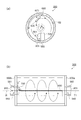
ドラム部300には、図3に示すように、少なくとも繊維を含む材料が空気中で通過する複数の開口311を有する開口部310と、開口311を有しない筒状部315とを有している。開口部310と筒状部315は溶接やネジなどで締結され、一体的に回転する。ドラム部300は、均一の厚みを有するステンレス鋼等の金属板を用いて筒型に形成されており、その両端には開放口306が設けられている。   As shown in FIG. 3, the drum portion 300 includes an opening portion 310 having a plurality of openings 311 through which a material containing at least fibers passes in the air, and a cylindrical portion 315 not having the opening 311. . The opening 310 and the cylindrical portion 315 are fastened by welding or screws, and rotate integrally. The drum unit 300 is formed in a cylindrical shape using a metal plate such as stainless steel having a uniform thickness, and open ports 306 are provided at both ends thereof.

開口部310は、複数の開口311(パンチングメタル)が設けられている。当該開口311から分散された繊維を含む材料が通過するように構成され、繊維を含む材料の大きさ、種類等により開口311の大きさや形成領域等が適宜設定されている。なお、開口部310は、パンチングメタルに限定されず、金網材であってもよい。複数の開口311の大きさ(面積)は同じで、それぞれが等間隔で配置されている。これにより、開口311を通過した材料は均一な厚み、密度でメッシュベルト73上に堆積する。また、開口311を通過する際に、絡みあった繊維はほぐされる。筒状部315は、開口311等を有しない部分であり、ハウジング部400と接する部分である。   The opening 310 is provided with a plurality of openings 311 (punching metal). The material containing the fiber dispersed from the opening 311 is configured to pass through, and the size, formation region, and the like of the opening 311 are appropriately set depending on the size and type of the material containing the fiber. The opening 310 is not limited to punching metal, and may be a wire mesh material. The plurality of openings 311 have the same size (area) and are arranged at equal intervals. Thereby, the material that has passed through the opening 311 is deposited on the mesh belt 73 with a uniform thickness and density. Moreover, the entangled fiber is loosened when passing through the opening 311. The cylindrical portion 315 is a portion that does not have the opening 311 and the like, and is a portion that contacts the housing portion 400.

ハウジング部400は、図2に示すように、枠体401を有し、ドラム部300の開口部310が枠体401の内側に来るように、ハウジング部400がドラム部300の一部を囲っている。つまり、ハウジング部400の内側の空間内にドラム部300の開口部310が位置している。そして、ハウジング部400と筒状部315とが接している。本実施形態では、図3に示すように、ドラム部300は、回転中心軸Rの延在方向に沿って、筒状部315a、開口部310、筒状部315bを有している。また、ハウジング部400は、図2に示すように、筒状部315a,315bにおける回転中心軸Rから離れる側の表面(円筒面)S1と接している。このように、ハウジング部400と筒状部315a,315bとが接することにより、開口311から通過した繊維を含む材料等をハウジング部400の内部から外側への拡散を抑制することができる。また、ドラム部300の回転軸方向Rにおいてドラム部300の内側にハウジング部400が配置されるため、ドラム部300の回転軸方向Rにおけるドラム部300の幅寸法よりも、ハウジング部400の幅寸法の方を短くする構成を得ることが可能となり、装置構成を小型にすることができる。なお、ハウジング部400の下方は、ホッパー部56が設けられている。なお、本実施形態では、選別部50のドラム部300が回転することで分級物が開口311を通過する。そして、ドラム部300の回転中心軸Rは水平方向である。   As shown in FIG. 2, the housing part 400 includes a frame body 401, and the housing part 400 surrounds a part of the drum part 300 so that the opening 310 of the drum part 300 is located inside the frame body 401. Yes. That is, the opening 310 of the drum part 300 is located in the space inside the housing part 400. The housing portion 400 and the cylindrical portion 315 are in contact with each other. In the present embodiment, as shown in FIG. 3, the drum portion 300 includes a cylindrical portion 315 a, an opening portion 310, and a cylindrical portion 315 b along the extending direction of the rotation center axis R. As shown in FIG. 2, the housing part 400 is in contact with the surface (cylindrical surface) S1 on the side away from the rotation center axis R in the cylindrical parts 315a and 315b. Thus, the housing part 400 and the cylindrical parts 315a and 315b are in contact with each other, so that the diffusion of the material containing the fibers passed through the opening 311 from the inside to the outside of the housing part 400 can be suppressed. Further, since the housing part 400 is arranged inside the drum part 300 in the rotation axis direction R of the drum part 300, the width dimension of the housing part 400 is larger than the width dimension of the drum part 300 in the rotation axis direction R of the drum part 300. Therefore, it is possible to obtain a configuration in which the length is shorter, and the device configuration can be reduced in size. Note that a hopper portion 56 is provided below the housing portion 400. In the present embodiment, the classified material passes through the opening 311 as the drum unit 300 of the sorting unit 50 rotates. And the rotation center axis | shaft R of the drum part 300 is a horizontal direction.

また、分級部40内の気流により選別部50に供給される分級物の回転方向と、選別部50の回転方向とが、同じ方向である。具体的には、図2に示すように、分級部40から選別部50内に搬送される分級物の搬送方向T1において、分級物が同一方向にのみ回転しながら搬送される。すなわち、分級部40における気流の発生方向と選別部50のドラム部300の回転方向とが一致するように構成されている。   Further, the rotation direction of the classified product supplied to the sorting unit 50 by the airflow in the classifying unit 40 and the rotation direction of the sorting unit 50 are the same direction. Specifically, as shown in FIG. 2, the classified product is conveyed while rotating only in the same direction in the conveyance direction T <b> 1 of the classified product conveyed from the classification unit 40 into the sorting unit 50. That is, the airflow generation direction in the classification unit 40 and the rotation direction of the drum unit 300 of the selection unit 50 are configured to coincide with each other.

ハウジング部400は、パイルシール部410を有し、筒状部315の表面S1とパイルシール部410とが接している。パイルシール部410は、例えば、ベース部と、ベース部の一方面側に密に植えつけられた複数の繊維とで構成されたものである。パイルシール部は、ドラム部300の開口311から通過した繊維が通過できない程度に密に複数の繊維が植えつけられている。そして、パイルシール部410のベース部の他方面とハウジング部400の枠体接合面401aとが接合され、パイルシール部410の繊維の先端部が筒状部315の表面S1に接するように構成されている。パイルシール部410が接する筒状部315の表面S1は開口はない。また、少なくともパイルシール部410が接する表面S1は凸凹も無いのが望ましい。これにより、ハウジング部400の枠体401とドラム部300の筒状部315との隙間がパイルシール部410によってほぼ塞がれる。従って、ドラム部300の開口311から通過した繊維を含む材料等をハウジング部400の内部に留め、ハウジング部400の外側への排出を抑制することができる。また、ドラム部300は回転中心軸R回りに回転した際、筒状部315とパイルシール部410との摺動部における摩耗が抑制され、ドラム部300への回転負荷を低減することができる。なお、パイルシール部410の繊維の長さは、ハウジング部400の枠体401とドラム部300の筒状部315との間隔よりも長くなるように設定する。パイルシール部410が確実に筒状部315に接するためである。   The housing part 400 has a pile seal part 410, and the surface S1 of the cylindrical part 315 and the pile seal part 410 are in contact with each other. The pile seal part 410 is composed of, for example, a base part and a plurality of fibers densely planted on one side of the base part. In the pile seal portion, a plurality of fibers are planted so densely that fibers that have passed through the opening 311 of the drum portion 300 cannot pass. Then, the other surface of the base portion of the pile seal portion 410 and the frame joint surface 401a of the housing portion 400 are joined, and the tip of the fiber of the pile seal portion 410 is configured to contact the surface S1 of the tubular portion 315. ing. The surface S1 of the cylindrical part 315 with which the pile seal part 410 contacts has no opening. Further, it is desirable that at least the surface S1 with which the pile seal portion 410 is in contact has no unevenness. As a result, the gap between the frame 401 of the housing part 400 and the cylindrical part 315 of the drum part 300 is almost closed by the pile seal part 410. Therefore, the material containing the fiber that has passed through the opening 311 of the drum part 300 can be retained inside the housing part 400 and the discharge to the outside of the housing part 400 can be suppressed. Further, when the drum portion 300 rotates around the rotation center axis R, wear at the sliding portion between the tubular portion 315 and the pile seal portion 410 is suppressed, and the rotational load on the drum portion 300 can be reduced. In addition, the length of the fiber of the pile seal part 410 is set so that it may become longer than the space | interval of the frame 401 of the housing part 400, and the cylindrical part 315 of the drum part 300. FIG. This is because the pile seal portion 410 is surely in contact with the tubular portion 315.

また、本実施形態の選別部50では、図2及び図4に示すように、ドラム部300における回転中心軸Rの延接方向の両端には、回転しない2つの側部500(500a,500b)を有している。そして、本実施形態の選別部50では、一方の側部500aに備えられ、ドラム部300に材料を導入する導入部540と、他方の側部500bに備えられ、導入部540よりも鉛直方向における下方側に位置し、開口311を通過しなかった材料である残留物を排出する排出部550と、を備えている。なお、ドラム部300は図示しない支持部により回転可能に支持されている。   Further, in the sorting unit 50 of the present embodiment, as shown in FIGS. 2 and 4, two side portions 500 (500 a and 500 b) that do not rotate are provided at both ends in the extending direction of the rotation center axis R in the drum unit 300. have. In the sorting unit 50 according to the present embodiment, the side part 500 a is provided with an introduction part 540 that introduces material into the drum part 300, and the other side part 500 b is provided in the vertical direction with respect to the introduction part 540. A discharge portion 550 that is located on the lower side and discharges a residue that is a material that has not passed through the opening 311. The drum unit 300 is rotatably supported by a support unit (not shown).

側部500a、500bは筒状部315a、315bの外側に固定のフランジ部501、503を有し、筒状部315とフランジ部501、503とは第2パイルシール部510を介して接している。側部500a、500bは、図示しない外部フレームに固定されている。側部500aには、繊維を含む材料をドラム部300内部に供給するための導入部540の一部を構成する材料供給口560が設けられている。側部500bには、開口311を通過しなかった材料である残留物を排出する排出部550の一部を構成する材料排出口561が設けられている。材料供給口560の配置位置は、回転中心軸Rと同じ中央部、或いは、回転中心軸Rよりも鉛直方向における上側に離間する位置に配置されている。なお、本実施形態では、図4に示すように、材料供給口560の配置位置は、回転中心軸Rと同じ位置、すなわち、材料供給口560の中心が回転中心軸Rと同じ位置である。選別部50のドラム部300内の材料は下方に溜まるので、材料供給口560を回転中心軸Rと同じ位置に配置することにより、ドラム部300の側部500aのほぼ真ん中から材料が供給される。すなわち、材料が溜まっていない(密度の低い)空間に供給されるので、材料同士の衝突が低減され、円滑に材料を供給することができる。   The side portions 500a and 500b have fixed flange portions 501 and 503 outside the tubular portions 315a and 315b, and the tubular portion 315 and the flange portions 501 and 503 are in contact with each other via the second pile seal portion 510. . The side parts 500a and 500b are fixed to an external frame (not shown). The side portion 500 a is provided with a material supply port 560 that constitutes a part of the introduction portion 540 for supplying a material containing fibers into the drum portion 300. The side portion 500b is provided with a material discharge port 561 that constitutes a part of a discharge portion 550 that discharges a residue that is a material that has not passed through the opening 311. The material supply port 560 is disposed at the same central portion as the rotation center axis R or at a position separated from the rotation center axis R in the vertical direction. In the present embodiment, as shown in FIG. 4, the material supply port 560 is disposed at the same position as the rotation center axis R, that is, the center of the material supply port 560 is the same position as the rotation center axis R. Since the material in the drum unit 300 of the sorting unit 50 accumulates downward, the material is supplied from almost the middle of the side portion 500a of the drum unit 300 by arranging the material supply port 560 at the same position as the rotation center axis R. . That is, since the material is supplied to the space where the material is not accumulated (low density), the collision between the materials is reduced and the material can be supplied smoothly.

第2パイルシール部510は、例えば、ベース部と、ベース部の一方面側に密に植えつけられた繊維とで構成されたものである。そして、本実施形態では、第2パイルシール部510のベース部の他方面とフランジ部501,503の表面501a、503aとが接合され、第2パイルシール部510の繊維の先端部が筒状部315の表面S1に接するように構成されている。これにより、フランジ部501、503とドラム部300の筒状部315との隙間が第2パイルシール部510によってほぼ塞がれる。従って、ドラム部300の繊維を含む材料等をドラム部300の筒状部315とフランジ部501,503との隙間から排出されることを抑制することができる。また、ドラム部300は側部500に対して回転中心軸R回りに回転するため、側部500と筒状部315との摺動部に第2パイルシール部510を用いることにより側部500と筒状部315との摩擦の発生が抑制され、ドラム部300への回転負荷を低減することができる。なお、第2パイルシール部510の繊維の長さは、フランジ部501,503とドラム部300の筒状部315との間隔よりも長くなるように設定する。第2パイルシール部510が確実に筒状部315に接するためである。   The second pile seal portion 510 is constituted by, for example, a base portion and fibers that are densely planted on one surface side of the base portion. In the present embodiment, the other surface of the base portion of the second pile seal portion 510 and the surfaces 501a and 503a of the flange portions 501 and 503 are joined, and the fiber tip portion of the second pile seal portion 510 is a cylindrical portion. It is comprised so that the surface S1 of 315 may be touched. As a result, the gap between the flange portions 501 and 503 and the cylindrical portion 315 of the drum portion 300 is almost closed by the second pile seal portion 510. Accordingly, it is possible to suppress the discharge of the material including the fibers of the drum unit 300 from the gap between the cylindrical portion 315 of the drum unit 300 and the flange portions 501 and 503. Further, since the drum portion 300 rotates around the rotation center axis R with respect to the side portion 500, the second pile seal portion 510 is used as a sliding portion between the side portion 500 and the cylindrical portion 315, so that the side portion 500 Generation of friction with the cylindrical portion 315 is suppressed, and the rotational load on the drum portion 300 can be reduced. The fiber length of the second pile seal portion 510 is set to be longer than the interval between the flange portions 501 and 503 and the cylindrical portion 315 of the drum portion 300. This is because the second pile seal portion 510 is surely in contact with the tubular portion 315.

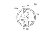
また、選別部には、図2及び図4から図6に示すように、ドラム部300内に固定部材600が固定して配置されている。固定部材600は、図5に示すように、ドラム部300内において、回転中心軸Rよりも鉛直方向における上側に離間して固定して配置されている。固定部材600は、回転するドラム部300とともに移動する材料と接触する部材である。回転中心軸Rの延設方向において、固定部材600は開口部310よりも大きく、ドラム部300よりも小さい。そのため、固定部材600は、少なくとも開口部310とともに移動する材料と接触する。   Further, as shown in FIGS. 2 and 4 to 6, the fixing member 600 is fixedly disposed in the drum unit 300 in the sorting unit. As shown in FIG. 5, the fixing member 600 is disposed in the drum portion 300 so as to be spaced apart and fixed above the rotation center axis R in the vertical direction. The fixing member 600 is a member that comes into contact with the material that moves together with the rotating drum unit 300. In the extending direction of the rotation center axis R, the fixing member 600 is larger than the opening portion 310 and smaller than the drum portion 300. Therefore, the fixing member 600 contacts at least the material that moves together with the opening 310.

そして、図5に示すように、固定部材600は2つの側部500a,500bに固定されている。本実施形態では、固定部材600と筒状部315の裏面S2との間に隙間(空間)660を設けた状態で、固定部材600と各側部500a,500bとが固定具610で接続固定されている。つまり、固定部材600はドラム部300とは離間して配置されている。これにより、ドラム部300は回転するが、固定部材600、側部500a,500bは回転しないように固定されている。また、固定具610は、固定部材600から固定部材600の長手方向に延びて各側部500a,500bに接続される。すなわち、固定部材600の鉛直方向における下方のドラム部300の回転中心軸R付近には固定具610等が配置しておらず、固定部材600に接触した材料は、障害物等に接触することなく下方に落下する。なお、固定具610は固定部材600よりも小さく、回転するドラム部300とともに移動する材料と接触しない。   And as shown in FIG. 5, the fixing member 600 is being fixed to the two side parts 500a and 500b. In the present embodiment, the fixing member 600 and each of the side portions 500a and 500b are connected and fixed by the fixing device 610 in a state where a gap (space) 660 is provided between the fixing member 600 and the back surface S2 of the cylindrical portion 315. ing. That is, the fixing member 600 is disposed away from the drum unit 300. Thereby, although the drum part 300 rotates, the fixing member 600 and the side parts 500a and 500b are fixed so as not to rotate. The fixing tool 610 extends from the fixing member 600 in the longitudinal direction of the fixing member 600 and is connected to the side portions 500a and 500b. That is, the fixture 610 or the like is not disposed in the vicinity of the rotation center axis R of the lower drum portion 300 in the vertical direction of the fixing member 600, and the material in contact with the fixing member 600 does not contact an obstacle or the like. Fall down. Fixing tool 610 is smaller than fixing member 600 and does not come into contact with the material that moves together with rotating drum unit 300.

また、固定部材600は、材料と接触する部分が面状である。本実施形態では、断面が四角い板状部材である。これにより、固定部材600に対して効率よく回転する繊維が接触する。また、固定部材600が容易な形状であるため、製造工数や設置工数等を低減することができる。なお、固定部材の材料と接触する部分は、面状であればよく、平面でも曲面でもよい。面状は、その面に凸や凹が無い状態を言う。凸や凹があると材料が引っかかってしまう。引っかからないように凸や凹の端部をテーパ形状にしたり湾曲形状にしていれば面状とみなす。   In addition, the fixing member 600 has a planar shape in contact with the material. In this embodiment, it is a plate-like member having a square cross section. Thereby, the fiber which rotates efficiently with respect to the fixing member 600 contacts. Further, since the fixing member 600 has an easy shape, the number of manufacturing steps, the number of installation steps, and the like can be reduced. In addition, the part which contacts the material of a fixing member should just be planar, and may be a plane or a curved surface. Planar shape refers to a state in which there is no protrusion or depression on the surface. If there is a convex or concave, the material will get caught. If the convex or concave ends are tapered or curved so as not to get caught, it is regarded as a planar shape.

また、図5に示すように、固定部材600は、回転中心軸を通る仮想鉛直面F1に対して傾斜している。本実施形態では、仮想鉛直面F1に対する固定部材600の設置角度θ1は、およそ40°〜50°に設定されているが、ドラム部300の容積の大きさ、回転速度数やドラム部300に投入される材料の容量等に応じて適宜設定することができる。また、本実施形態の固定部材600では、回転中心軸Rを通る仮想水平面F2よりもドラム部300内の鉛直方向における上側における回転方向において、仮想鉛直面F1よりも下流側に配置されている。これにより、ドラム部300の上方においてドラム部300の内壁に張り付いた材料が剥がされて下方側に落下する距離をより長くすることができる。これにより篩機能の効率を高めることができる。   As shown in FIG. 5, the fixing member 600 is inclined with respect to a virtual vertical plane F1 passing through the rotation center axis. In the present embodiment, the installation angle θ1 of the fixing member 600 with respect to the virtual vertical plane F1 is set to approximately 40 ° to 50 °, but the volume size of the drum unit 300, the rotational speed, and the drum unit 300 are input. It can set suitably according to the capacity | capacitance etc. of the material to be performed. Further, in the fixing member 600 of the present embodiment, the fixing member 600 is disposed on the downstream side of the virtual vertical plane F1 in the rotation direction on the upper side in the vertical direction in the drum unit 300 with respect to the virtual horizontal plane F2 passing through the rotation center axis R. Thereby, the material stuck to the inner wall of the drum part 300 above the drum part 300 is peeled off, and the distance at which the material falls downward can be made longer. Thereby, the efficiency of a sieve function can be improved.

さらに、図2及び図4から図6に示すように、選別部50は、ドラム部300内において残留物を排出部550に誘導する誘導部700を有している。当該誘導部700は、図2及び図5に示すように、回転中心軸Rの延接方向において排出部550側で、回転中心軸Rよりも鉛直方向における下方側に位置している。また、図5に示すように一方の側部500aを回転中心軸Rの延接方向に見た時に、誘導部700は排出部550に対して、ドラム部300の回転方向下流側に位置している。これにより、ドラム部300内の残留物を容易に排出部550の材料排出口561側に誘導させることができる。   Further, as shown in FIGS. 2 and 4 to 6, the sorting unit 50 includes a guide unit 700 that guides the residue to the discharge unit 550 in the drum unit 300. As shown in FIGS. 2 and 5, the guide portion 700 is located on the discharge portion 550 side in the extending direction of the rotation center axis R and on the lower side in the vertical direction than the rotation center axis R. Further, as shown in FIG. 5, when the one side portion 500 a is viewed in the extending direction of the rotation center axis R, the guide portion 700 is located on the downstream side in the rotation direction of the drum portion 300 with respect to the discharge portion 550. Yes. Thereby, the residue in the drum part 300 can be easily guided to the material discharge port 561 side of the discharge part 550.

本実施形態の誘導部700は断面が四角い板状部材で形成されている。そして、誘導部700は、他方の側部500bに備え付けられている。これにより、ドラム部300は回転するが、誘導部700、側部500a,500bは回転しないように構成されている。また、図6に示すように、ドラム部300の回転に伴って移動する残留物が誘導部700に当たり、排出部550側へ移動する方向に誘導部700は傾斜している。本実施形態では、回転中心軸に対して垂直な仮想鉛直面F3に対する誘導部700の設置角度θ2は、およそ60°〜70°に設定されているが、ドラム部300の容積の大きさ、回転速度数やドラム部300に投入される材料の容量等に応じて適宜設定することができる。   The guide part 700 of this embodiment is formed of a plate-like member having a square cross section. And the guidance | induction part 700 is equipped with the other side part 500b. Thus, the drum unit 300 rotates, but the guide unit 700 and the side units 500a and 500b are configured not to rotate. Further, as shown in FIG. 6, the residue that moves as the drum unit 300 rotates hits the guide unit 700, and the guide unit 700 is inclined in the direction of moving toward the discharge unit 550. In the present embodiment, the installation angle θ2 of the guide unit 700 with respect to the virtual vertical plane F3 perpendicular to the rotation center axis is set to approximately 60 ° to 70 °. It can be set as appropriate according to the speed number, the volume of the material charged into the drum unit 300, and the like.

また、排出部550の内側における鉛直方向の最下部はドラム部300の内側における鉛直方向の最下部と鉛直方向で同じ高さ、或いは、それよりも低くなるように設定されている。本実施形態では、図2及び図5に示すように、排出部550の材料排出口561における鉛直方向の最下部とドラム部300の内側における鉛直方向の最下部とが鉛直方向において同じ高さである。また、誘導部700の鉛直方向の最下部がドラム部300の内側における鉛直方向の最下部と鉛直方向において同じ高さである。このように、ドラム部300と材料排出口561(排出部550)とが鉛直方向の最下部において平坦化されるため、残留物は、ドラム部300と材料排出口561(排出部550)との間で引っかかることなく、ドラム部300から配管205に向けて円滑に搬送される。配管205は鉛直方向における下方に向けて延設しており、重力で下方へ搬送される。   Further, the lowermost portion in the vertical direction inside the discharge portion 550 is set to be the same height as or lower than the lowermost portion in the vertical direction inside the drum portion 300 in the vertical direction. In the present embodiment, as shown in FIGS. 2 and 5, the lowest part in the vertical direction at the material discharge port 561 of the discharge part 550 and the lowest part in the vertical direction inside the drum part 300 have the same height in the vertical direction. is there. Further, the lowermost portion in the vertical direction of the guiding portion 700 has the same height in the vertical direction as the lowermost portion in the vertical direction inside the drum portion 300. In this way, since the drum unit 300 and the material discharge port 561 (discharge unit 550) are flattened at the lowest part in the vertical direction, the residue remains between the drum unit 300 and the material discharge port 561 (discharge unit 550). It is smoothly transported from the drum unit 300 toward the pipe 205 without being caught in between. The pipe 205 extends downward in the vertical direction and is conveyed downward by gravity.

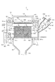
次に、図2及び図7を参照して、シート製造装置1の動作方法について説明する。図7は、シート製造装置の動作方法を示す説明図である。   Next, an operation method of the sheet manufacturing apparatus 1 will be described with reference to FIGS. 2 and 7. FIG. 7 is an explanatory diagram showing an operation method of the sheet manufacturing apparatus.

まず、解繊部30によって解繊された解繊物は、配管202を介して分級部40の導入口40aから気流に乗って導入される。分級部40に導入された解繊物の動きは、筒部41で円周運動に変わり、解繊物のサイズと密度により受ける遠心力の差によって分級される。そして、分級された分級物は搬送方向T1に対して一定方向に円周運動を維持しながら遠心力と重力によって円錐部42側に移動する。そして、円錐部42の下部の下部取出口40bから配管203を介して選別部50に搬送される。このとき、導入口40aから導入された気流のうち、下部取出口40bから出る残気流に乗って、分級物は選別部50に搬送される。なお、下部取出口40bから出る気流も円周運動を維持している。   First, the defibrated material defibrated by the defibrating unit 30 is introduced into the air stream from the introduction port 40a of the classifying unit 40 via the pipe 202. The movement of the defibrated material introduced into the classifying unit 40 is changed into a circumferential motion at the cylinder part 41, and is classified by the difference in centrifugal force received by the size and density of the defibrated material. The classified product moves toward the conical portion 42 by centrifugal force and gravity while maintaining a circumferential motion in a certain direction with respect to the transport direction T1. And it is conveyed to the selection part 50 via the piping 203 from the lower outlet 40b of the lower part of the cone part 42. FIG. At this time, of the airflow introduced from the introduction port 40a, the classified product is transported to the sorting unit 50 on the remaining airflow that exits from the lower outlet 40b. Note that the airflow from the lower outlet 40b also maintains the circumferential motion.

ここで、選別部50は、分級部40に対して下方に位置し、さらに、分級部40と選別部50とが常に鉛直方向における下方に向かう配管203で接続されているため、分級物が、重力によっても円滑に分級部40から選別部50に搬送される。   Here, the classification unit 50 is positioned below the classification unit 40, and further, the classification unit 40 and the selection unit 50 are always connected by the pipe 203 that is directed downward in the vertical direction. It is smoothly transported from the classification unit 40 to the sorting unit 50 even by gravity.

そして、選別部50では、ドラム部300のドラム部300が回転中心軸Rを中心として分級部40における分級物の回転方向と同じ方向に回転している状態で、分級物が導入部540の材料供給口560から選別部50内に導入される。そして、分級物はドラム部300の回転による遠心力により開口311を通過し、通過したものは通過物としてホッパー部56から配管204へ搬送される。この場合の通過物としては、開口311の目開きの大きさより短い繊維が主となる。一方、開口311を通過しなかったものは、残留物として開口311を通過せずに、排出部550から排出される。この場合の残留物は、開口311を通過できない長さの繊維や十分に解繊されなかった未解繊片や繊維同士が絡み合ったダマ等である。   In the sorting unit 50, the classified product is the material of the introduction unit 540 in a state where the drum unit 300 of the drum unit 300 rotates about the rotation center axis R in the same direction as the rotation direction of the classified product in the classifying unit 40. It is introduced into the sorting unit 50 from the supply port 560. Then, the classified product passes through the opening 311 due to the centrifugal force generated by the rotation of the drum unit 300, and the passed product is conveyed from the hopper unit 56 to the pipe 204 as a passing product. As the passing material in this case, fibers shorter than the size of the opening 311 are mainly used. On the other hand, what does not pass through the opening 311 is discharged from the discharge unit 550 as a residue without passing through the opening 311. The residue in this case is a fiber having a length that cannot pass through the opening 311, an undefibrated piece that has not been sufficiently defibrated, or a dama that is intertwined with fibers.

ここで、選別部50に導入された分級物(繊維を含む材料)は、ドラム部300の回転と同じ回転方向に移動するが、分級物の一部が、図7(a)に示すように、ドラム部300の回転中心軸Rよりも鉛直方向における上側に離間して配置された固定部材600に接触(衝突)し、接触した分級物が固定部材600から下方に落下する。これにより、開口部310の内壁に張り付いた材料が開口部310の内壁から剥がれ落ち、再び回転移動する。また、固定部材600とドラム部300は離間しているので、一部の材料は、開口部310の内壁と固定部材600との隙間660に流れ込む。このとき隙間660を通った材料は、開口部310の内壁と固定部材600とで形成される空間670において負圧により開口部310の内壁に張り付いた材料が引き剥がされ、再び開口部310内を回転移動する。また、固定部材に衝突したり下方に落下した衝撃で、絡み合った繊維同士が分散されほぐされる。ほぐされた繊維は、張り付いた材料が引き剥がされた開口部310を通過しやすくなる。さらに、開口部310の内壁に張り付いた材料は、引き剥がされることで位置が変わりやすくなる。そして、回転移動を繰り返す材料は、排出部550側に移動する。そして、材料のうち開口311を通過したものは通過物としてホッパー部56へ流動する。一方、回転運動を繰り返しても開口311を通過しなかったものは、残留物として排出部550側に回転移動する。   Here, the classified product (material containing fiber) introduced into the sorting unit 50 moves in the same rotation direction as the rotation of the drum unit 300, but a part of the classified product is as shown in FIG. Then, it comes into contact (collision) with the fixing member 600 that is arranged to be separated from the rotation center axis R of the drum portion 300 in the vertical direction, and the contacted classified article falls downward from the fixing member 600. As a result, the material stuck to the inner wall of the opening 310 is peeled off from the inner wall of the opening 310 and rotates again. In addition, since the fixing member 600 and the drum portion 300 are separated from each other, a part of the material flows into the gap 660 between the inner wall of the opening 310 and the fixing member 600. At this time, the material that has passed through the gap 660 is peeled off by the negative pressure in the space 670 formed by the inner wall of the opening 310 and the fixing member 600, and the inside of the opening 310 again. Move the rotation. Further, the entangled fibers are dispersed and loosened by an impact that collides with the fixing member or falls downward. The loosened fibers are likely to pass through the opening 310 where the adhered material has been peeled off. Further, the material stuck to the inner wall of the opening 310 is easily changed in position by being peeled off. And the material which repeats rotational movement moves to the discharge part 550 side. Then, the material that has passed through the opening 311 flows to the hopper 56 as a passing material. On the other hand, what does not pass through the opening 311 even after repeating the rotational movement is rotated and moved to the discharge unit 550 side as a residue.

そして、排出部550側に回転移動した残留物は、図7(b)に示すように、側部500bの配管205に対応する位置に配置された誘導部700に衝突するとともに、誘導部700における排出部550側へ移動する方向の傾斜により、配管205側に誘導される。これにより、ドラム部300内の残留物が効率よく排出される。排出部550から排出された残留物は、配管205を介して解繊部30に搬送される(図1参照)。   Then, as shown in FIG. 7B, the residue that has rotated and moved to the discharge unit 550 side collides with the guide unit 700 disposed at a position corresponding to the pipe 205 of the side unit 500 b, and in the guide unit 700. It is guided to the pipe 205 side by the inclination in the direction of moving to the discharge unit 550 side. Thereby, the residue in the drum part 300 is discharged | emitted efficiently. The residue discharged from the discharge unit 550 is conveyed to the defibrating unit 30 via the pipe 205 (see FIG. 1).

以上、上記実施形態によれば、以下の効果を得ることができる。   As mentioned above, according to the said embodiment, the following effects can be acquired.

選別部50のドラム部300を回転中心軸回りに回転させると、ドラム部300の回転に伴ってドラム部300内の繊維を含む材料もドラム部300の回転方向に回転する。また、材料は遠心力により開口部310の内周面に押し圧され、開口311の目開きの大きさよりも小さい繊維は開口311を通過する。開口311を通過しない材料は、開口部310の内周面に材料が張り付いた状態で回転移動する。ここで、ドラム部300内におけるドラム部300の回転中心軸Rよりも鉛直方向における上側に離間した位置には固定部材600が配置されており、開口部310の内周面に材料が張り付いた状態で回転移動する材料は固定部材600に接触(衝突)する。そして、接触した材料は、開口部310の内周面から剥がれ落ち、剥がれ落ちた材料は、再度回転移動される。このとき、繊維が絡み合ったダマなどは衝突や落下の際に絡み合った状態が解けてほぐされる。これにより、開口311を通過しやすくなり、篩機能の効率を向上させることができる。また、開口部310の内周面(裏面S2)に張り付いた材料を剥がすことで、複数の開口を露出させることができ、材料が開口を通過しやすくすることができる。   When the drum unit 300 of the sorting unit 50 is rotated about the rotation center axis, the material including the fibers in the drum unit 300 is rotated in the rotation direction of the drum unit 300 as the drum unit 300 rotates. Further, the material is pressed against the inner peripheral surface of the opening 310 by centrifugal force, and the fibers smaller than the opening size of the opening 311 pass through the opening 311. The material that does not pass through the opening 311 rotates and moves in a state where the material sticks to the inner peripheral surface of the opening 310. Here, the fixing member 600 is disposed at a position spaced apart from the rotation center axis R of the drum unit 300 in the vertical direction in the drum unit 300, and the material sticks to the inner peripheral surface of the opening 310. The material that rotates and moves in the state contacts (impacts) the fixed member 600. The contacted material is peeled off from the inner peripheral surface of the opening 310, and the peeled material is rotated and moved again. At this time, the entangled fibers are entangled and unraveled in the event of a collision or drop. Thereby, it becomes easy to pass through the opening 311 and the efficiency of the sieving function can be improved. Further, by peeling off the material stuck to the inner peripheral surface (back surface S2) of the opening 310, a plurality of openings can be exposed, and the material can easily pass through the openings.

本発明は上述した実施形態に限定されず、上述した実施形態に種々の変更や改良などを加えることが可能である。変形例を以下に述べる。   The present invention is not limited to the above-described embodiment, and various modifications and improvements can be added to the above-described embodiment. A modification will be described below.

(変形例1)上記実施形態では、分級部40と選別部50とを配管203で接続したが、この構成に限定されない。例えば、分級部40と選別部50とが管路等を介さずに直結された構成であってもよい。図8は、変形例にかかる分級部及び選別部の構成を示す詳細図である。図8に示すように、分級部40’と選別部50’とが直結されている。このようにすれば、分級部40’と選別部50’との間に分級物が留まる箇所が低減されるため、確実に分級物を分級部40’から選別部50’に搬送することができる。さらに、分級部40’は円筒または円錐部を有し、円筒または円錐部の仮想中心線C1’は鉛直方向に対し傾斜している。このようにすれば、分級部40’と選別部50’とを容易に直結することができる。なお、他の部分は、上記実施形態の構成と同様なので説明を省略する。   (Modification 1) In the said embodiment, although the classification part 40 and the selection part 50 were connected by the piping 203, it is not limited to this structure. For example, a configuration in which the classification unit 40 and the selection unit 50 are directly connected without using a pipeline or the like may be used. FIG. 8 is a detailed diagram illustrating the configuration of the classification unit and the selection unit according to the modification. As shown in FIG. 8, the classification unit 40 'and the selection unit 50' are directly connected. In this way, the number of places where the classified product stays between the classification unit 40 ′ and the sorting unit 50 ′ is reduced, so that the classified product can be reliably conveyed from the classification unit 40 ′ to the sorting unit 50 ′. . Furthermore, the classification part 40 'has a cylinder or a cone part, and the virtual center line C1' of the cylinder or cone part is inclined with respect to the vertical direction. In this way, the classification unit 40 'and the selection unit 50' can be easily connected directly. The other parts are the same as those in the above embodiment, and the description thereof is omitted.

(変形例2)上記実施形態では、ドラム部300の開口部310の内周面は平滑面であったが、この構成に限定されない。例えば、開口部310の内周面に凹凸を有していてもよい。図9は、変形例にかかる分級部の構成を示す概略部である。図9に示すように、開口部310の内周面に凸部333が形成されており、これにより内周面に凹凸が形成される。凸部333の形状は、ドラム部300の回転中心軸Rの延設方向に沿って延在する形状であってもよいし、ドット状であってもよい。このようにすれば、凹凸によって材料がドラム部300とともに移動しやすくなり、さらに篩機能を向上させることができる。   (Modification 2) In the above embodiment, the inner peripheral surface of the opening 310 of the drum unit 300 is a smooth surface, but is not limited to this configuration. For example, the inner peripheral surface of the opening 310 may have irregularities. FIG. 9 is a schematic part showing the configuration of the classifying part according to the modification. As shown in FIG. 9, the convex part 333 is formed in the internal peripheral surface of the opening part 310, and an unevenness | corrugation is formed in an internal peripheral surface by this. The shape of the convex portion 333 may be a shape extending along the extending direction of the rotation center axis R of the drum portion 300, or may be a dot shape. If it does in this way, it will become easy to move material with the drum part 300 by an unevenness | corrugation, and can improve a sieve function further.

(変形例3)上記実施形態では、ドラム部300の回転中心軸は水平方向としたが、これに限定されない。例えば、ドラム部300の回転中心軸Rが水平面に対して傾斜した構成であってもよい。この場合、排出部550側の方が、導入部540側よりも低くなるようにドラム部300の回転中心軸Rが水平面に対して傾斜させる。このようにすれば、ドラム部300内の残留物が重力で排出部550側に移動するため、さらに残留物の排出性を向上させることができる。   (Modification 3) In the above embodiment, the rotation center axis of the drum unit 300 is set in the horizontal direction, but the present invention is not limited to this. For example, the rotation center axis R of the drum unit 300 may be inclined with respect to the horizontal plane. In this case, the rotation center axis R of the drum unit 300 is inclined with respect to the horizontal plane so that the discharge unit 550 side is lower than the introduction unit 540 side. In this way, since the residue in the drum unit 300 moves to the discharge unit 550 side by gravity, the discharge property of the residue can be further improved.

(変形例4)上記実施形態では、固定部材600を選別部50のドラム部300に採用したが、これに限定されない。分散部70のフォーミングドラム71に採用してもよい。フォーミングドラム71の小孔(開口)も繊維を含む材料を通過させているので、選別部の一つとみなせる。この場合、フォーミングドラム71の小孔が開口311と同様の機能となる。その際、フォーミングドラム71の小孔の大きさは開口311と同じか大きい。これにより、開口311を通過した通過物はフォーミングドラム71の小孔を通過できるようになる。そのため、フォーミングドラム71の小孔を通過できない通過物はないので、フォーミングドラム71には誘導部700はない。   (Modification 4) In the above embodiment, the fixing member 600 is employed in the drum section 300 of the sorting section 50. However, the present invention is not limited to this. You may employ | adopt for the forming drum 71 of the dispersion | distribution part 70. FIG. Since the small hole (opening) of the forming drum 71 also allows the material containing the fiber to pass therethrough, it can be regarded as one of the sorting sections. In this case, the small hole of the forming drum 71 has the same function as the opening 311. At that time, the size of the small hole of the forming drum 71 is the same as or larger than that of the opening 311. Thereby, the passing material that has passed through the opening 311 can pass through the small hole of the forming drum 71. Therefore, since there is no passing material that cannot pass through the small hole of the forming drum 71, the forming drum 71 does not have the guiding portion 700.

(変形例5)上記実施形態ではドラム部300を回転する駆動部を図示しなかった。駆動部は、例えば、図2においてハウジング部400の外側(パイルシール部410と接する部分より外側)に位置する筒状部315に歯車を設け、ベルトや歯車により駆動する。これにより、駆動部がハウジング部400の外側に位置することで、駆動部に繊維を含む材料が挟まって駆動不良になったり、駆動の負荷が増大することを抑制できる。   (Modification 5) In the above embodiment, the drive unit that rotates the drum unit 300 is not shown. For example, the drive unit is provided with a gear on a cylindrical portion 315 located outside the housing portion 400 (outside the portion in contact with the pile seal portion 410) in FIG. 2, and is driven by a belt or a gear. Thereby, it can suppress that the drive part is located in the outer side of the housing part 400, the material containing a fiber is pinched | interposed into a drive part, it becomes a drive failure, or the load of a drive increases.

(変形例6)上記実施形態では開口部310と筒状部315は外表面及び内表面が面一となるような図であるが、段差があってもよい。   (Modification 6) In the above embodiment, the opening 310 and the cylindrical portion 315 are diagrams in which the outer surface and the inner surface are flush with each other, but there may be steps.

(変形例7)上記実施形態において、「同じ」、「均一」、「等間隔」、「円」などの言葉は、誤差や誤差の累積などを含み、完全に同じや均一や等間隔や真円でなくてもよい。   (Modification 7) In the above embodiment, the words “same”, “uniform”, “equally spaced”, “circle”, etc. include errors and accumulated errors, and are completely the same, uniform, equally spaced, and true. It doesn't have to be a circle.

(変形例8)上記実施形態では、回転中心軸Rの延設方向において、固定部材600は開口部310よりも大きく、ドラム部300よりも小さいとした。これに限らず、ドラム部300と同じ大きさとしてもよい。その際には、固定具610は無くしてもよく、固定部材600が側部500a,500bに固定されてもよい。また、固定部材600の両側に固定具610を備えているが、片側だけでもよい。特に排出部550側は、誘導部700で残留物を排出するために、固定部材600で材料を引き剥がさないほうがよい。そのため、排出部550側だけ、固定具610を設けるか、固定部材600に切り欠きを設け、材料と接触しないようにしてもよい。   (Modification 8) In the above embodiment, the fixing member 600 is larger than the opening 310 and smaller than the drum 300 in the extending direction of the rotation center axis R. However, the size is not limited to this, and the drum unit 300 may have the same size. In that case, the fixing tool 610 may be omitted, and the fixing member 600 may be fixed to the side portions 500a and 500b. Moreover, although the fixing tool 610 is provided on both sides of the fixing member 600, only one side may be used. In particular, on the discharge part 550 side, in order to discharge the residue by the guide part 700, it is better not to peel off the material by the fixing member 600. Therefore, the fixing device 610 may be provided only on the discharge unit 550 side, or the fixing member 600 may be provided with a notch so as not to contact the material.

(変形例9)上記実施形態では、材料供給口560を側部500aにおいて回転中心軸Rと同じ中央部か、回転中心軸Rより鉛直方向における上側に離間した位置とした。これに限らず、中央部から水平方向に移動(離間)させた位置でもよい。その場合は、回転中心軸Rから、固定部材600とは反対側に向かって水平方向で移動させて位置がよい。これにより、材料供給口560から供給される材料と、固定部材600に接触し落下した材料が干渉することがなく、材料供給口560から速やかに供給されることが可能となる。   (Modification 9) In the above embodiment, the material supply port 560 is located at the same central portion as the rotation center axis R in the side portion 500a or at a position separated from the rotation center axis R in the vertical direction. The position is not limited to this, and may be a position moved (separated) in the horizontal direction from the center. In that case, the position is good by moving in the horizontal direction from the rotation center axis R toward the side opposite to the fixed member 600. As a result, the material supplied from the material supply port 560 and the material that comes into contact with the fixing member 600 and does not interfere do not interfere with each other, and can be supplied quickly from the material supply port 560.

(変形例10)上記実施形態では、固定部材600において、鉛直方向における上側の端部と下側の端部は回転中心軸Rと平行な図であった。しかし、固定部材600の鉛直方向における下側の端部は回転中心軸Rから鉛直方向における上側に離間していれば平行でなくてもよい。つまり、固定部材600と回転中心軸Rの離間距離は、一定とは限らない。なお、固定部材600の鉛直方向における上側の端部は、回転中心軸Rと平行が望ましい。   (Modification 10) In the above embodiment, in the fixing member 600, the upper end and the lower end in the vertical direction are parallel to the rotation center axis R. However, the lower end of the fixing member 600 in the vertical direction may not be parallel as long as it is separated from the rotation center axis R in the vertical direction. That is, the separation distance between the fixed member 600 and the rotation center axis R is not always constant. The upper end of the fixing member 600 in the vertical direction is preferably parallel to the rotation center axis R.

1…シート製造装置、10…供給部、20…粗砕部、30…解繊部、40…分級部、40a…導入口、40b…下部取出口、40c…上部排気口、41…筒部、42…円錐部、50…選別部、60…添加物投入部、70…分散部、73…メッシュベルト、75…サクション装置、80…受け部、100…搬送部、110…切断部、120…切断部前ローラー、125…切断部後ローラー、130…後切断部、140…予備加熱加圧部、150…加熱加圧部、160…スタッカー、200…成形部、201,202,203,204,205,206…配管、300…ドラム部、306…開放口、310…開口部、311…開口、315,315a,315b…筒状部、333…凸部、400…ハウジング部、410…パイルシール部、500,500a,500b…側部、501…フランジ部、501a…表面、503…フランジ部、510…第2パイルシール部、540…導入部、550…排出部、560…材料供給口、600…固定部材、610…固定具、660…隙間、700…誘導部。   DESCRIPTION OF SYMBOLS 1 ... Sheet manufacturing apparatus, 10 ... Supply part, 20 ... Crushing part, 30 ... Defibration part, 40 ... Classification part, 40a ... Inlet port, 40b ... Lower outlet, 40c ... Upper exhaust port, 41 ... Tube part, 42 ... Conical part, 50 ... Sorting part, 60 ... Additive feeding part, 70 ... Dispersing part, 73 ... Mesh belt, 75 ... Suction device, 80 ... Receiving part, 100 ... Conveying part, 110 ... Cutting part, 120 ... Cutting Front roller, 125 ... Roller after cutting part, 130 ... Rear cutting part, 140 ... Preheating and pressing part, 150 ... Heat and pressing part, 160 ... Stacker, 200 ... Molding part, 201, 202, 203, 204, 205 , 206 ... piping, 300 ... drum part, 306 ... opening, 310 ... opening, 311 ... opening, 315, 315a, 315b ... cylindrical part, 333 ... convex part, 400 ... housing part, 410 ... pile seal part, 500 500a, 500b ... side part, 501 ... flange part, 501a ... surface, 503 ... flange part, 510 ... second pile seal part, 540 ... introduction part, 550 ... discharge part, 560 ... material supply port, 600 ... fixing member, 610: Fixing tool, 660: Gap, 700: Guide part.

Claims (7)

繊維を含む材料を複数の開口を通過させる選別部と、
前記開口を通過した前記材料を用いてシートを成形する成形部と、を備えるシート製造装置であって、
前記選別部は、
円筒面に前記複数の開口を有し回転中心軸回りに回転する円筒部と、
前記円筒部内において、前記回転中心軸に対し上側に離間して配置され、前記円筒部とは離間し、回転せずに固定されている固定部材と、を有することを特徴とするシート製造装置。
A sorting section for passing a material containing fibers through a plurality of openings;
A sheet manufacturing apparatus comprising: a molding unit that molds a sheet using the material that has passed through the opening,
The sorting unit
A cylindrical portion having a plurality of openings on a cylindrical surface and rotating about a rotation center axis;
Within the cylindrical portion, the rotation center axis to be spaced upward, spaced from said cylindrical portion, the sheet manufacturing apparatus characterized by comprising a fixing member which is fixed to not rotate, the .
請求項1に記載のシート製造装置において、
前記固定部材は前記材料と接触可能であり、前記材料と接触する部分が面状であることを特徴とするシート製造装置。
In the sheet manufacturing apparatus according to claim 1,
The sheet manufacturing apparatus according to claim 1, wherein the fixing member is capable of contacting the material, and a portion in contact with the material is planar.
請求項2に記載のシート製造装置において、
前記固定部材は、断面が四角い板状部材であることを特徴とするシート製造装置。
In the sheet manufacturing apparatus according to claim 2,
The sheet manufacturing apparatus, wherein the fixing member is a plate-like member having a square cross section.
請求項1から請求項3のいずれか一項に記載のシート製造装置において、
前記円筒部における前記回転中心軸の延方向に離間して両端に備えられ、回転しない2つの側部を有し、
前記固定部材は前記2つの側部に固定されることを特徴とするシート製造装置。
In the sheet manufacturing apparatus according to any one of claims 1 to 3,
Provided at both ends at a distance from each other in the extending direction of the rotation axis of the cylindrical part, has two sides which does not rotate,
The sheet manufacturing apparatus, wherein the fixing member is fixed to the two side portions.
請求項1から請求項4のいずれか一項に記載のシート製造装置において、
前記固定部材は、仮想鉛直面に対して傾斜していることを特徴とするシート製造装置。
In the sheet manufacturing apparatus according to any one of claims 1 to 4,
The sheet manufacturing apparatus, wherein the fixing member is inclined with respect to a virtual vertical plane.
請求項1から請求項5のいずれか一項に記載のシート製造装置において、
前記回転中心軸は水平方向に配置され、
前記回転中心軸を通る仮想水平面よりも前記円筒部内の上側における回転方向において、前記回転中心軸を通る仮想鉛直面よりも下流側に前記固定部材を有することを特徴とするシート製造装置。
In the sheet manufacturing apparatus according to any one of claims 1 to 5,
The rotation center axis is arranged in a horizontal direction,
The sheet manufacturing apparatus having the fixing member on a downstream side of a virtual vertical plane passing through the rotation center axis in a rotation direction on the upper side in the cylindrical portion with respect to a virtual horizontal plane passing through the rotation center axis.
請求項1から請求項6のいずれか一項に記載のシート製造装置において、
前記円筒部の内周面に凹凸を有することを特徴とするシート製造装置。
In the sheet manufacturing apparatus according to any one of claims 1 to 6,
The sheet manufacturing apparatus according to claim 1, wherein the cylindrical portion has irregularities on an inner peripheral surface thereof.
JP2013266613A 2013-12-25 2013-12-25 Sheet manufacturing equipment Active JP6248616B2 (en)

Priority Applications (2)

Application Number Priority Date Filing Date Title
JP2013266613A JP6248616B2 (en) 2013-12-25 2013-12-25 Sheet manufacturing equipment
US14/569,930 US9255360B2 (en) 2013-12-25 2014-12-15 Sheet manufacturing apparatus

Applications Claiming Priority (1)

Application Number Priority Date Filing Date Title
JP2013266613A JP6248616B2 (en) 2013-12-25 2013-12-25 Sheet manufacturing equipment

Publications (3)

Publication Number Publication Date
JP2015120317A JP2015120317A (en) 2015-07-02
JP2015120317A5 JP2015120317A5 (en) 2016-12-15
JP6248616B2 true JP6248616B2 (en) 2017-12-20

Family

ID=53532423

Family Applications (1)

Application Number Title Priority Date Filing Date
JP2013266613A Active JP6248616B2 (en) 2013-12-25 2013-12-25 Sheet manufacturing equipment

Country Status (1)

Country Link
JP (1) JP6248616B2 (en)

Families Citing this family (1)

* Cited by examiner, † Cited by third party
Publication number Priority date Publication date Assignee Title
JP7306194B2 (en) 2019-09-27 2023-07-11 セイコーエプソン株式会社 Fiber processing device and fiber body manufacturing device

Family Cites Families (6)

* Cited by examiner, † Cited by third party
Publication number Priority date Publication date Assignee Title
AU547989B2 (en) * 1980-01-18 1985-11-14 Christensen, J.H.M. A system for dry forming of paper or other sheet material of particles of fibres
JP2902631B1 (en) * 1998-05-12 1999-06-07 義晴 高柳 Centrifugal washing and dewatering machine for stock
FI107818B (en) * 1999-05-27 2001-10-15 Bki Holding Corp Screen tube for use in dry forming of web material
FI20095769A (en) * 2009-07-07 2011-01-08 Andritz Oy Apparatus for handling a fiber suspension
JP5720255B2 (en) * 2011-01-12 2015-05-20 セイコーエプソン株式会社 Paper recycling apparatus and paper recycling method
JP6210308B2 (en) * 2013-12-25 2017-10-11 セイコーエプソン株式会社 Sheet manufacturing equipment

Also Published As

Publication number Publication date
JP2015120317A (en) 2015-07-02

Similar Documents

Publication Publication Date Title
JP6492576B2 (en) Sheet manufacturing equipment
JP6277836B2 (en) Sheet manufacturing equipment
JP6354154B2 (en) Sheet manufacturing equipment
US9776213B2 (en) Sheet manufacturing apparatus
JP6357767B2 (en) Sheet manufacturing equipment
JP2016098470A (en) Sheet manufacturing apparatus
JP2015161047A (en) Sheet production apparatus
JP6569719B2 (en) Sheet manufacturing equipment
JP6252171B2 (en) Sheet manufacturing apparatus and sheet manufacturing method
JP6252234B2 (en) Sheet manufacturing equipment
JP6248615B2 (en) Sheet manufacturing equipment
JP6210308B2 (en) Sheet manufacturing equipment
JP6418309B2 (en) Sheet manufacturing equipment
JP6340881B2 (en) Sheet manufacturing equipment
JP6248616B2 (en) Sheet manufacturing equipment
JP2016137608A (en) Sheet manufacturing apparatus
JP2016182726A (en) Sheet manufacturing apparatus, and sheet manufacturing method
US9255360B2 (en) Sheet manufacturing apparatus
JP6724963B2 (en) Sheet manufacturing equipment
JP2016113735A (en) Apparatus for manufacturing sheet
JP2016168678A (en) Sheet production apparatus and sheet production method
JP6439347B2 (en) Sheet manufacturing equipment
JP6464717B2 (en) Sheet manufacturing apparatus and sheet manufacturing method
JP6508362B2 (en) Sheet manufacturing equipment
JP6277831B2 (en) Sheet manufacturing equipment

Legal Events

Date Code Title Description
RD04 Notification of resignation of power of attorney

Free format text: JAPANESE INTERMEDIATE CODE: A7424

Effective date: 20160617

RD03 Notification of appointment of power of attorney

Free format text: JAPANESE INTERMEDIATE CODE: A7423

Effective date: 20160627

A521 Written amendment

Free format text: JAPANESE INTERMEDIATE CODE: A523

Effective date: 20161027

A621 Written request for application examination

Free format text: JAPANESE INTERMEDIATE CODE: A621

Effective date: 20161027

A977 Report on retrieval

Free format text: JAPANESE INTERMEDIATE CODE: A971007

Effective date: 20171013

TRDD Decision of grant or rejection written
A01 Written decision to grant a patent or to grant a registration (utility model)

Free format text: JAPANESE INTERMEDIATE CODE: A01

Effective date: 20171024

A61 First payment of annual fees (during grant procedure)

Free format text: JAPANESE INTERMEDIATE CODE: A61

Effective date: 20171106

R150 Certificate of patent or registration of utility model

Ref document number: 6248616

Country of ref document: JP

Free format text: JAPANESE INTERMEDIATE CODE: R150