EP2664536B1 - Schiffsantriebsystem - Google Patents
Schiffsantriebsystem Download PDFInfo
- Publication number
- EP2664536B1 EP2664536B1 EP13002554.7A EP13002554A EP2664536B1 EP 2664536 B1 EP2664536 B1 EP 2664536B1 EP 13002554 A EP13002554 A EP 13002554A EP 2664536 B1 EP2664536 B1 EP 2664536B1
- Authority
- EP
- European Patent Office
- Prior art keywords
- clutch
- transmission
- drive
- electric motor
- ship
- Prior art date
- Legal status (The legal status is an assumption and is not a legal conclusion. Google has not performed a legal analysis and makes no representation as to the accuracy of the status listed.)
- Active
Links
Images



Classifications
-
- B—PERFORMING OPERATIONS; TRANSPORTING
- B63—SHIPS OR OTHER WATERBORNE VESSELS; RELATED EQUIPMENT
- B63H—MARINE PROPULSION OR STEERING
- B63H21/00—Use of propulsion power plant or units on vessels
- B63H21/20—Use of propulsion power plant or units on vessels the vessels being powered by combinations of different types of propulsion units
-
- B—PERFORMING OPERATIONS; TRANSPORTING
- B63—SHIPS OR OTHER WATERBORNE VESSELS; RELATED EQUIPMENT
- B63H—MARINE PROPULSION OR STEERING
- B63H21/00—Use of propulsion power plant or units on vessels
- B63H21/12—Use of propulsion power plant or units on vessels the vessels being motor-driven
- B63H21/17—Use of propulsion power plant or units on vessels the vessels being motor-driven by electric motor
-
- B—PERFORMING OPERATIONS; TRANSPORTING
- B63—SHIPS OR OTHER WATERBORNE VESSELS; RELATED EQUIPMENT
- B63H—MARINE PROPULSION OR STEERING
- B63H21/00—Use of propulsion power plant or units on vessels
- B63H21/30—Mounting of propulsion plant or unit, e.g. for anti-vibration purposes
- B63H21/305—Mounting of propulsion plant or unit, e.g. for anti-vibration purposes with passive vibration damping
-
- B—PERFORMING OPERATIONS; TRANSPORTING
- B63—SHIPS OR OTHER WATERBORNE VESSELS; RELATED EQUIPMENT
- B63H—MARINE PROPULSION OR STEERING
- B63H23/00—Transmitting power from propulsion power plant to propulsive elements
- B63H23/02—Transmitting power from propulsion power plant to propulsive elements with mechanical gearing
- B63H23/10—Transmitting power from propulsion power plant to propulsive elements with mechanical gearing for transmitting drive from more than one propulsion power unit
- B63H23/12—Transmitting power from propulsion power plant to propulsive elements with mechanical gearing for transmitting drive from more than one propulsion power unit allowing combined use of the propulsion power units
-
- B—PERFORMING OPERATIONS; TRANSPORTING
- B63—SHIPS OR OTHER WATERBORNE VESSELS; RELATED EQUIPMENT
- B63H—MARINE PROPULSION OR STEERING
- B63H23/00—Transmitting power from propulsion power plant to propulsive elements
- B63H23/30—Transmitting power from propulsion power plant to propulsive elements characterised by use of clutches
-
- B—PERFORMING OPERATIONS; TRANSPORTING
- B63—SHIPS OR OTHER WATERBORNE VESSELS; RELATED EQUIPMENT
- B63H—MARINE PROPULSION OR STEERING
- B63H21/00—Use of propulsion power plant or units on vessels
- B63H21/20—Use of propulsion power plant or units on vessels the vessels being powered by combinations of different types of propulsion units
- B63H2021/202—Use of propulsion power plant or units on vessels the vessels being powered by combinations of different types of propulsion units of hybrid electric type
- B63H2021/205—Use of propulsion power plant or units on vessels the vessels being powered by combinations of different types of propulsion units of hybrid electric type the second power unit being of the internal combustion engine type, or the like, e.g. a Diesel engine
-
- Y—GENERAL TAGGING OF NEW TECHNOLOGICAL DEVELOPMENTS; GENERAL TAGGING OF CROSS-SECTIONAL TECHNOLOGIES SPANNING OVER SEVERAL SECTIONS OF THE IPC; TECHNICAL SUBJECTS COVERED BY FORMER USPC CROSS-REFERENCE ART COLLECTIONS [XRACs] AND DIGESTS
- Y02—TECHNOLOGIES OR APPLICATIONS FOR MITIGATION OR ADAPTATION AGAINST CLIMATE CHANGE
- Y02T—CLIMATE CHANGE MITIGATION TECHNOLOGIES RELATED TO TRANSPORTATION
- Y02T70/00—Maritime or waterways transport
- Y02T70/50—Measures to reduce greenhouse gas emissions related to the propulsion system
- Y02T70/5218—Less carbon-intensive fuels, e.g. natural gas, biofuels
- Y02T70/5236—Renewable or hybrid-electric solutions
Definitions
- the invention relates to a marine propulsion system having a drive shaft train configured to receive rotational propulsion power from an internal combustion engine and to supply rotary propulsion power to a propulsion element, and an electric motor configured to supply rotational propulsion power to the propulsion shaft train.
- Such a ship propulsion system is eg off DE 100 61 578 A1 known, as the internal combustion engine, for example, a slow-running diesel engine is provided, the crankshaft is connected via a drive shaft forming a propeller shaft with a ship propeller as a propulsion element.
- a slow-running continuously operating electric motor for supporting the diesel engine is arranged, wherein the armature shaft of the electric motor is formed by the propeller shaft, so that the electric motor drives directly into the propeller shaft.
- a rated power of the electric motor is at least 5 percent of the rated power of the internal combustion engine.
- the low-speed electric motor must be sized and sturdily provided to provide the required rotary drive power at the low speed of about 100 rpm, and the full magnitude of shock effects occurring at the propeller shaft (such as torque shocks) due to direct shock initiation. can withstand damage. This requires a significantly higher weight and a larger footprint and higher cost of the electric motor compared to systems with high-speed electric motor.
- the invention has for its object to provide a marine propulsion system with a combination of drive shaft strand and electric motor as mentioned above, which has a lower production cost.
- an electric motor from a rated speed of about about 600 U / min is understood according to the invention.
- the high speed electric motor according to the invention has a rated speed of above 600 rpm to about 1800 rpm and above, and preferably a weight well below the weight of the low speed electric motor.
- the internal combustion engine drives into the second transmission interface of the first transmission, the internal combustion engine preferably having a diesel engine and / or a gas turbine.
- either the electric motor or the first transmission can be shut down mechanically depending on the desired mode of operation, or the electric motor and the first transmission can both be in rotary drive connection with the drive shaft train and the drive element in order to supply this rotary drive power.
- the first transmission which preferably functions as a main transmission, can be mechanically shut down, whereby the noise produced by the marine propulsion system can be greatly reduced.
- the necessary or desired drive torque for rotational driving of the preferably designed as a ship propeller propulsion element can be realized at significantly lower weight and space for electric motor and reduction gear. Due to the high drive speed of the electric motor and the resulting torque is a much smaller clutch (eg multi-plate clutch) required as in a system with low-speed electric motor, when the multi-plate clutch is attached to the drive shaft of the high-speed electric motor. Overall, the component costs can thus be considerably reduced.
- a clutch eg multi-plate clutch
- the ship propulsion system has storage means which are designed such that both the electric motor and the gearbox that is supplied with rotational drive power can be supported elastically on a ship foundation.
- the storage means comprise a frame construction on which the electric motor and the transmission fed by it with rotary drive power are held together, and a plurality of elastic elements which are attached to the frame construction, so that the frame construction can be supported on the ship foundation via the elastic elements.
- the elastic elements are preferably soft elastic, so that their structure-borne sound damping properties are even more pronounced.
- the frame construction is designed to be structurally sound-damping, for example by being constructed with hollow profiles, the hollow profiles being filled, for example, with structure-borne noise-damping material.
- the (second) transmission with the electric motor can stand on a separate frame or be stored via elastic elements directly on the ship foundation.
- the electric motor is mounted on a frame with the transmission powered by this rotary drive power, the frame is fixed on the ship foundation by means of elastic bearings (elastic elements).
- the transmission output of the second transmission is drive-connected to the drive shaft train via dome means permitting axial and angular and radial misalignment.
- the coupling means are preferably provided with structure-borne sound damping (for example via an elastic design).
- the clutch input of the second shift clutch is drive-connected to an output shaft of the electric motor that provides the rotational drive power
- the clutch output of the second clutch is drive-connected to the transmission input of the second transmission
- This embodiment of the invention provides a possibility of arranging the second clutch, which is e.g. for the aft side arrangement of the second transmission and the electric motor with respect to the first transmission.
- the second clutch is incorporated in the drive shaft train, so that the clutch output of the second clutch is in rotational drive connection with the transmission output of the second transmission and so that the clutch input of the second clutch is in rotary drive connection with the clutch input of the first clutch.
- This embodiment of the invention provides a further possibility for the arrangement of the second clutch, which is e.g. for the pre-ship arrangement of the second gear and the electric motor with respect to the first gear. It is particularly advantageous in this embodiment of the invention that can be shut down mechanically with separation of the second clutch in addition to the electric motor and the second transmission, so that the mechanical drag losses and noise in pure engine operation can be reduced.
- the first gear and the second gear are connected to each other via a flexible oil-tight connection, such as a flexible oil pan.
- a hood is additionally provided, which provides a sound enclosure for the electric motor and the latter supplied with rotary drive power transmission.
- a combined arrangement of a high-speed electric motor and a speed-reducing gearbox powered by it with rotary drive power can be realized on a common frame supported on a ship's foundation, wherein a double-cardan and elastic shaft offset clutch is provided from a reduction gear output shaft to the drive shaft train or a propeller shaft provided therein and preferably also an additional elastic bearing between the electric motor and speed-reducing gear can be provided to the frame.
- a fast-rotating electric motor is thus placed from the main gearbox (first gearbox) from the front of the ship or aft.
- the ship propulsion system according to the invention can be realized by the two clutches that in electric motor operation, the complete main transmission is stationary and the electric motor when required (for example, in the inoperative state) can be uncoupled.
- the noise generated by the drive system in electric motor operation as low as possible.
- Advantages of a high-speed electric motor compared to a low-speed electric motor are that the engine weight and the cost of the faster-running electric motor are significantly lower.
- the electric motor is uncoupled in pure diesel engine and / or gas turbine operation and the main transmission (first transmission) is uncoupled in pure electric motor operation.
- the ship propulsion system according to the invention a higher efficiency in electric motor operation and in gas turbine operation / diesel engine operation than in integrating the electric motor in the main transmission can be achieved.
- CODELAG Diesel, Electric and Gas Turbine
- FIGS. 1 and 2 a marine propulsion system 1 according to a first embodiment of the invention will be described.
- the marine propulsion system 1 has a drive shaft train 10, a first clutch 30, a first transmission 40, a second transmission 50, a high-speed electric motor 60, a second clutch 70, a frame construction 80, a hood 90, a propelling element 100 designed as a ship propeller an internal combustion engine (not shown).
- the drive shaft train 10 has a propeller shaft 15 drivingly connected to the propelling member 100, a two-piece intermediate shaft 20 drivingly connected to the propeller shaft 15 via a flange joint 16 and extending through the first gear 40, and a torsion shaft 25 which is drivingly connected to the intermediate shaft 20 via an axial and angular displacement permitting flexible coupling 21 (eg comprising an elastic membrane) and which extends through the second gear 50.
- a propeller shaft 15 drivingly connected to the propelling member 100
- a two-piece intermediate shaft 20 drivingly connected to the propeller shaft 15 via a flange joint 16 and extending through the first gear 40
- a torsion shaft 25 which is drivingly connected to the intermediate shaft 20 via an axial and angular displacement permitting flexible coupling 21 (eg comprising an elastic membrane) and which extends through the second gear 50.
- the intermediate shaft 20 is rotatably supported via rotary bearings 22, 23, 24 on a housing 40 a of the first transmission 40. How out Fig.1 is apparent in addition to the first gear 40 and the first and the second clutch 30, 70 housed in this housing 40a.
- the first clutch or disconnect clutch 30 is designed as a multi-plate clutch and has a clutch input 31, to which a plurality of inner clutch plates are provided, and a clutch output 32, on which a plurality of clutch outer plates are provided.
- the clutch input 31 is formed by a portion of the intermediate shaft 20, whereas the clutch output 32 is formed by a sleeve-like outer disk carrier mounted rotatably on the intermediate shaft 20 via a radial-axial bearing 32a.
- the clutch input 31 and the clutch output 32 are by mutual in or out of frictional engagement of the clutch inner plates and clutch outer plates selectively in and out of drive connection can be brought.
- a thrust bearing (not designated) is also integrated into the housing 40a of the first transmission 40
- the clutch input 31 of the first clutch 30 is drivingly connected to the drive shaft train 10, so that rotary drive power to the drive element 100 is transferable.
- the first transmission 40 has two transmission interfaces, via which the first transmission 40 each rotational drive power can be fed and discharged from this, wherein one of the two transmission interfaces with the clutch output 32 of the first clutch 30 is drivingly connected.
- the first transmission interface of the first transmission 40 drivingly connected to the clutch output 32 of the first clutch 30 is formed by a hollow shaft 41 through which the intermediate shaft 20 extends and which is rotatably supported on the housing 40 a of the first transmission 40 via rotary bearings 42.
- the hollow shaft 41 is drivingly connected to the clutch output 32 of the first clutch 30 via an axial and angular displacement permitting flexible coupling 35 (having, for example, an elastic diaphragm) and a torsion sleeve 36.
- the second transmission interface is formed by a gear 43 mounted on the hollow shaft 41.
- the gear 43 drives via not shown further transmission means, the internal combustion engine, which preferably has a diesel engine and / or a gas turbine.
- the drive shaft train 10 is configured to receive rotary drive power from the engine and to supply rotary drive power to the drive element 100.
- the second clutch or separating clutch 70 is designed as a multi-plate clutch and has a clutch input 71, on which a plurality of clutch inner plates are provided, and a clutch output 72, on which a plurality of clutch outer plates are provided.
- the clutch input 71 is formed by a portion of the intermediate shaft 20, whereas the clutch output 72 from a via a radial-axial bearing 72 a rotatably mounted on a in Fig.1 left part of the intermediate shaft 20 mounted sleeve-like outer disk carrier is formed.
- the clutch input 71 and the clutch output 72 are by mutual in or out of frictional engagement of the inner clutch plates and clutch outer plates selectively in and out of drive connection can be brought.
- the second transmission 50 has a transmission input 51 in the form of a drive shaft and a transmission output 52 in drive connection with the transmission input 51 in the form of a hollow shaft, which is rotatably supported in a housing 50a of the second transmission 50 by means of rotation bearings 52a.
- the other components of the second transmission 50 are also suitably mounted or supported on the housing 50a thereof.
- the second transmission 50 is configured to provide speed reduction (speed reduction) from its transmission input 51 to its transmission output 52.
- the hollow shaft (i.e., transmission output 52) is drivingly coupled to the torsion shaft 25 of the drive shaft train 10 via axial and angular and radial displacement allowing gimbal elastic coupling means 55.
- a flange 56 is mounted on the torsion shaft 25, which is drivingly connected via an elastic diaphragm 57 with the hollow shaft (ie, the transmission output 52) of the second transmission 50.
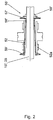
- FIG Fig.2 An alternative embodiment of such coupling means 55 'is exemplified in FIG Fig.2 shown.
- a flange 56 ' is mounted on the torsion shaft 25, which is drive-connected via a first elastic membrane 57' with a torsion sleeve 58 '.
- the torsion sleeve 58 ' is drivingly connected to the hollow shaft (ie, the transmission output 52) of the second gear 50 via a second resilient diaphragm 59'.
- the coupling means 55, 55 ' have body-sound-damping properties.
- the high speed electric motor 60 has a rated speed of typically above about 600 rpm to about 1800 rpm and above.
- the electric motor 60 is configured to supply rotational drive power to the drive shaft train 10 via the transmission input 51 of the second transmission 50. More specifically, the electric motor 60 has an output shaft 61 providing rotational drive power, which is drive-connected via a flexible coupling 65 to the transmission input 51 (the drive shaft) of the second transmission 50.
- the frame structure 80 is formed so that the electric motor 60 and the second gear 50 are mutually supported thereon.
- a plurality of elastic members (e.g., rubber buffers) 81 are attached to the frame structure 80 so that the frame structure 80 can be elastically supported by the elastic members 81 on a ship foundation (not shown).
- the elastic elements 81 are formed soft elastic.
- the frame structure 80 and the elastic elements 81 attached thereto thus form storage means with which both the electric motor 60 and the second gear 50 can be elastically supported on the ship foundation.
- the frame structure 80 may be structurally embodied structure-sound damping, for example by being constructed with hollow profiles, wherein the hollow profiles are filled, for example, with structure-borne sound absorbing material.
- the hood 90 is configured to provide sound enclosure for the electric motor 60 and the second transmission 50, thereby providing additional noise reduction with respect to the noise emitted by the electric motor 60 and the second transmission 50 in their operation.
- first gear 40 and the second gear 50 may be interconnected via a flexible oil-tight connection.
- the second clutch 70 is so involved in the drive shaft 10 that the clutch output 72 of the second clutch 70 is in rotational drive connection with the transmission output 52 of the second transmission 50 and that the clutch input 71 of the second clutch 70 in rotary drive connection with the clutch input 31 of the first clutch 30 is (to reduce the size of the clutch 70, this can also be arranged on the transmission input 51).
- the clutch input 71 and the clutch output 72 of the second clutch 70 may be selectively brought into and out of driving communication with each other to establish or disconnect a drive connection of the electric motor 60 to the clutch input 31 of the first clutch 30 and to the propulsion element 100.
- the second clutch 70 is disengaged, wherein the clutch input 71 and clutch output 72 except Drive connection are brought together. Further, the first clutch 30 is engaged, wherein the clutch input 31 and clutch output 32 are brought into drive connection with each other. In this way, the second gear 50 and the electric motor 60 are mechanically shut down.
- the second shift clutch 70 is engaged, with its clutch input 71 and clutch output 72 being brought into drive connection with one another. Further, the first clutch 30 is disengaged, wherein the clutch input 31 and clutch output 32 are brought out of drive connection with each other. In this way, the first transmission 40 (and preferably also the internal combustion engine) is mechanically shut down, so that the noise in the pure electric motor operation is extremely low.
- both the first clutch 30 and the second clutch 70 is engaged.
- the internal combustion engine includes a diesel engine and a gas turbine
- CODELAG operation is possible, with all three prime movers (electric motor, diesel engine, and gas turbine) generating the rotary drive power for the prime mover 100.
- FIGS. 2 to 4 a marine propulsion system 1 'according to a second embodiment of the invention will be described which, except for some differences explained below, is similar to the marine propulsion system 1 according to the first embodiment of the invention. Accordingly, in the following description, the same or similar components are denoted by the same reference numerals. Differences in the design of the components are characterized by the addition of an apostrophe to the reference numerals.
- the ship propulsion system 1 according to the second embodiment of the invention, the first transmission, which similar to that with reference to Fig.1 described first gear 40 is constructed and which here, however, with respect to the Figures 3 and 4 is arranged to the right of the second transmission 50.
- the high-speed electric motor 60 and the second gear 50 are arranged from the first transmission (constituting a main transmission) on the aft and output side of the first transmission, respectively, into which the internal combustion engine drives
- the coupling connecting the electric motor 60 and the second gear 50 is formed as the second clutch 65 ', the clutch input of the second clutch 65' being drive-connected to the output shaft 61 of the electric motor 60 providing the rotational drive power, and the clutch output of the first clutch 65 ' second clutch 65 'is drivingly connected to the transmission input 51 of the second transmission 50.
- the drive shaft train 10 ' the propeller shaft 15', which is drivingly connected to the driving element 100 and extending through the second transmission 50 therethrough, and a one-piece intermediate shaft (not shown), via a Flange connection 16 'is drive-connected to the propeller shaft 15' and extends through the first transmission.
- the second clutch 65 ' is now arranged between the electric motor 60 and the second transmission 50, only the first clutch is arranged in the housing of the first transmission and thus the intermediate shaft can be made in one piece.
- the hollow shaft (ie, the transmission output 52) of the second transmission 50 is over the in Fig.2 gimbal gimbal permitting gimbal elastic coupling means 55 'are drivingly connected to the propeller shaft 15' of the drive shaft train 10 '.
- the flange 56 ' is mounted on the propeller shaft 15', which is drivingly connected to the torsion sleeve 58 'via the first elastic diaphragm 57'.
- the torsion sleeve 58 ' is drivingly coupled to the hollow shaft (i.e., the transmission output 52) of the second gear 50 via the second resilient diaphragm 59'.
- any couplings permitting axial and angular misalignment used within the scope of the invention can be designed both as membrane couplings as described above and as tooth couplings.
- the clutch input and the clutch output of the second clutch 65 ' can be selectively brought into and out of drive connection with each other to establish a drive connection of the electric motor 60 to the clutch input of the first clutch housed in the housing of the first transmission and to the drive element 100 or separate.
- the second embodiment of the invention provides an arrangement of high-speed electric motor 60 with the second gear 50 and frame construction 80 via offset-receiving clutch on the propeller shaft 15 'the output side of the first transmission with internal combustion engine.
- the clutch 70 (see Fig.1 ) omitted and replaced by the high-speed and thus smaller clutch 65 '.
- the second clutch 65 ' is disengaged, wherein the clutch input and clutch output are brought out of drive connection with each other. Further, the first clutch is engaged, wherein the clutch input and clutch output are brought into drive connection with each other. In this way, the electric motor 60 is mechanically shut down, but the second gear 50 is further rotated.
- the second clutch 65 is engaged, with its clutch input and clutch output being brought into drive connection with each other. Further, the first clutch is disengaged, wherein the clutch input and clutch output are brought out of drive connection with each other. In this way, the first transmission (and preferably also the internal combustion engine) is mechanically shut down, so that the noise in the pure electric motor operation is extremely low.
- both the first clutch and the second clutch 65 ' is engaged.
- the engine includes a diesel engine and a gas turbine
- CODELAG operation is again possible, with all three prime movers (electric motor, diesel engine, and gas turbine) generating the rotational drive power for the propulsion element 100.
- a marine propulsion system is modified from the marine propulsion system 1 'according to the second embodiment of the invention to include only the high-speed electric motor 60, the gearbox 50 (reduction gear) coupled thereto via the clutch 65', and the axial and Angular and radial offset balancing gimbal elastic coupling means 55 'for connecting the transmission output 52 of the transmission 50 with the propeller shaft 15' has.
- a first transmission or main transmission 40 and an internal combustion engine driving therein are not provided according to the third embodiment of the invention.
- frame structure 80 and the attached elastic elements 81 may be provided so that the high-speed electric motor 60 and the reducing gear 50 are held together or supported on the frame structure 80 and the frame structure 80 via the elastic members 81 is elastically and body silencer supported on the ship's foundation.
- the frame structure 80 and the attached elastic elements 81 in this case again form storage means with which both the high-speed electric motor 60 and the step-down gear 50 are resiliently supported on the ship's foundation.
Landscapes
- Chemical & Material Sciences (AREA)
- Engineering & Computer Science (AREA)
- Combustion & Propulsion (AREA)
- Mechanical Engineering (AREA)
- Ocean & Marine Engineering (AREA)
- Connection Of Motors, Electrical Generators, Mechanical Devices, And The Like (AREA)
- Structure Of Transmissions (AREA)
Description
- Die Erfindung betrifft ein Schiffsantriebssystem mit einem Antriebswellenstrang, der eingerichtet ist, Drehantriebsleistung von einer Brennkraftmaschine zu empfangen und einem Vortriebselement Drehantriebsleistung zuzuführen, und einem Elektromotor, der eingerichtet ist, dem Antriebswellenstrang Drehantriebsleistung zuzuführen.
- Ein solches Schiffsantriebssystem ist z.B. aus
DE 100 61 578 A1 bekannt, wobei als Brennkraftmaschine z.B. ein langsamlaufender Dieselmotor vorgesehen ist, dessen Kurbelwelle über eine einen Antriebswellenstrang bildende Propellerwelle mit einem Schiffspropeller als Vortriebselement verbunden ist. Zwischen dem Dieselmotor und dem Schiffspropeller ist ein langsamlaufender ständig in Betrieb befindlicher Elektromotor zur Unterstützung des Dieselmotors angeordnet, wobei die Ankerwelle des Elektromotors von der Propellerwelle gebildet ist, so dass der Elektromotor unmittelbar in die Propellerwelle eintreibt. Eine Nennleistung des Elektromotors liegt bei wenigstens 5 Prozent der Nennleistung der Brennkraftmaschine. - Durch den direkten Eintrieb des Elektromotors in die Propellerwelle ist kein zusätzliches Getriebe erforderlich. Allerdings muss in diesem Fall der langsamlaufende Elektromotor so groß und stabil dimensioniert sein, dass er die erforderliche Drehantriebsleistung bei der geringen Drehzahl von etwa 100 U/min bereitstellen und aufgrund der direkten Schockeinleitung die volle Stärke von an der Propellerwelle auftretenden Schockwirkungen (wie z.B. Drehmomentschocks) beschädigungsfrei ertragen kann. Dies bedingt ein deutlich höheres Gewicht und einen größeren Platzbedarf und höhere Anschaffungskosten des Elektromotors gegenüber Anlagen mit schnelllaufendem Elektromotor.
- Soll der Elektromotor von der Propellerwelle abkuppelbar sein, so wäre wegen der geringen Nenndrehzahl von z.B. im Bereich 50 bis 150 U/min und dem daraus resultierenden hohen Drehmoment eine relativ große Schaltkupplung bzw. Trennkupplung (wie z.B. eine Lamellenkupplung) notwendig.
- Außerdem wird durch den direkten Eintrieb des Elektromotors in die Propellerwelle und dessen in der Regel starre Aufstellung auf dem Schiffsfundament auch dessen Körperschall direkt in die Propellerwelle und das Schiffsfundament eingeleitet, so dass im Elektromotorbetrieb eine starke Geräuschentwicklung auftreten kann.
- Aus der
US 5 616 056 A1 , aus derGB 410 031 A US 2009/186537 A1 und aus derDE 10 2009 00656 A1 sind weitere Schiffsantriebssysteme bekannt. - Der Erfindung liegt die Aufgabe zugrunde, ein Schiffsantriebssystem mit einer wie eingangsgenannten Kombination von Antriebswellenstrang und Elektromotor bereitzustellen, welches einen geringeren Herstellungsaufwand aufweist.
- Dies wird mit einem Schiffsantriebssystem gemäß Anspruch 1 erreicht. Weiterbildungen der Erfindung sind in den abhängigen Ansprüchen definiert.
- Unter einem schnelllaufenden Elektromotor wird gemäß der Erfindung ein Elektromotor ab einer Nenndrehzahl von über etwa 600 U/min verstanden. Bevorzugt hat der schnelllaufende Elektromotor gemäß der Erfindung eine Nenndrehzahl von über 600 U/min bis etwa 1800 U/min und auch darüber und bevorzugt ein Gewicht von deutlich unter dem Gewicht des langsamlaufenden Elektromotors.
- In die zweite Getriebeschnittstelle des ersten Getriebes treibt die Brennkraftmaschine ein, wobei die Brennkraftmaschine bevorzugt einen Dieselmotor und/oder eine Gasturbine aufweist.
- Dadurch, dass die beiden Schaltkupplungen vorgesehen sind, kann je nach gewünschter Betriebsart entweder der Elektromotor oder das erste Getriebe mechanisch stillgelegt werden oder können auch der Elektromotor und das erste Getriebe beide in Drehantriebsverbindung mit dem Antriebswellenstrang und dem Vortriebselement stehen, um diesem Drehantriebsleistung zuzuführen.
- Somit kann in einem reinen Elektromotorbetrieb das erste Getriebe, welches bevorzugt als ein Hauptgetriebe fungiert, mechanisch stillgelegt werden, womit die von dem Schiffsantriebssystem bewirkte Geräuschentwicklung stark reduziert werden kann.
- Durch die Verwendung eines schnelllaufenden Elektromotors in Kombination mit einem drehzahluntersetzenden Getriebe kann das zum Drehantreiben des bevorzugt als Schiffspropeller ausgebildeten Vortriebselements notwendige bzw. gewünschte Antriebsmoment bei deutlich geringerem Gewicht und Bauraum für Elektromotor und Untersetzungsgetriebe realisiert werden. Aufgrund der hohen Antriebsdrehzahl des Elektromotors und des dadurch resultierendes Drehmoments ist eine deutlich kleinere Schaltkupplung (z.B. Lamellenkupplung) erforderlich als bei einer Anlage mit langsamlaufendem Elektromotor, wenn die Lamellenkupplung an der Antriebswelle des schnelllaufenden Elektromotors angebaut wird. Insgesamt lassen sich somit die Komponentenkosten beträchtlich reduzieren.
- Gemäß einer Ausführungsform der Erfindung weist das Schiffsantriebssystem Lagerungsmittel auf, die so ausgebildet sind, dass sowohl der Elektromotor als auch das von diesem mit Drehantriebsleistung gespeiste Getriebe elastisch an einem Schiffsfundament abstützbar sind.
- Auf diese Weise wird die Einleitung von Körperschall in das Schiffsfundament erheblich reduziert, so dass die Geräuschentwicklung insbesondere im Elektromotorbetrieb noch mehr reduziert werden kann.
- Bevorzugt weisen die Lagerungsmittel eine Rahmenkonstruktion, an welcher der Elektromotor und das von diesem mit Drehantriebsleistung gespeiste Getriebe gemeinsam gehalten sind, und eine Mehrzahl von Elastikelementen auf, die an der Rahmenkonstruktion angebracht sind, so dass die Rahmenkonstruktion über die Elastikelemente an dem Schiffsfundament abstützbar ist.
- Die Elastikelemente sind bevorzugt weichelastisch ausgebildet, so dass deren körperschalldämpfende Eigenschaften noch stärker ausgeprägt sind.
- Gemäß noch einer Ausführungsform der Erfindung ist die Rahmenkonstruktion konstruktiv körperschalldämpfend ausgebildet, indem sie z.B. mit Hohlprofilen konstruiert ist, wobei die Hohlprofile z.B. mit körperschalldämpfendem Material gefüllt sind.
- Allgemein kann das (zweite) Getriebe mit dem Elektromotor auf einem separaten Rahmen stehen oder über Elastikelemente direkt auf dem Schifffundament gelagert werden. Wenn der Elektromotor mit dem von diesem mit Drehantriebsleistung gespeisten Getriebe auf einem Rahmen gelagert wird, wird der Rahmen mit Hilfe einer elastischen Lagerung (Elastikelemente) auf dem Schiffsfundament befestigt.
- Durch die weichelastische Aufstellung einzeln oder mit gemeinsamen Rahmen für Elektromotor und von diesem mit Drehantriebsleistung gespeistem drehzahluntersetzendem Getriebe kann eine geringere Körperschalleinleitung in das Schiffsfundament realisiert werden.
- Gemäß der Erfindung ist der Getriebeausgang des zweiten Getriebes über Axial-und-Winkel-und-Radialversatz erlaubende Kuppelmittel mit dem Antriebswellenstrang antriebsverbunden.
- Durch diese Axial-und-Winkel-und Radialversatz erlaubenden kardanischen bevorzugt elastischen Kuppelmittel können größere Verlagerungen zwischen erstem Getriebe (bevorzugt Hauptgetriebe) und Propellerwelle sowie elastisch gelagertem zweitem Getriebe und Elektromotor zuverlässig ausgeglichen werden. Bevorzugt sind die Kuppelmittel mit Körperschalldämpfung (z.B. via elastischer Ausgestaltung) versehen.
- Durch diese elastische Kupplung des zweiten Getriebes mit dem Antriebswellenstrang (welcher eine Propellerwelle aufweist) kann die Körperschalleinleitung in den Antriebswellenstrang reduziert werden.
- Durch die elastische Aufstellung und Einbindung des zweiten Getriebes und des Elektromotors in das Schiffsantriebssystem wird die im Betrieb an diesen wirkende Schockbelastung deutlich reduziert.
- Gemäß noch einer Ausführungsform der Erfindung ist der Kupplungseingang der zweiten Schaltkupplung mit einer die Drehantriebsleistung bereitstellenden Abtriebswelle des Elektromotors antriebsverbunden und ist der Kupplungsausgang der zweiten Schaltkupplung mit dem Getriebeeingang des zweiten Getriebes antriebsverbunden.
- Diese Ausgestaltung der Erfindung stellt eine Möglichkeit zur Anordnung der zweiten Schaltkupplung bereit, welche sich z.B. für die in Bezug auf das erste Getriebe achternseitige Anordnung von zweitem Getriebe und Elektromotor eignet.
- Gemäß einer weiteren Ausführungsform der Erfindung ist die zweite Schaltkupplung in den Antriebswellenstrang eingebunden, so dass der Kupplungsausgang der zweiten Schaltkupplung in Drehantriebsverbindung mit dem Getriebeausgang des zweiten Getriebes steht und so dass der Kupplungseingang der zweiten Schaltkupplung in Drehantriebsverbindung mit dem Kupplungseingang der ersten Schaltkupplung steht.
- Diese Ausgestaltung der Erfindung stellt eine weitere Möglichkeit zur Anordnung der zweiten Schaltkupplung bereit, welche sich z.B. für die in Bezug auf das erste Getriebe vorschiffsseitige Anordnung von zweitem Getriebe und Elektromotor eignet. Besonders vorteilhaft bei dieser Ausgestaltung der Erfindung ist, dass sich mit Trennen der zweiten Schaltkupplung neben dem Elektromotor auch das zweite Getriebe mechanisch stilllegen lässt, so dass die mechanischen Schleppverluste und die Geräuschentwicklung im reinen Brennkraftmaschinenbetrieb reduziert werden.
- Gemäß noch einer weiteren Ausführungsform der Erfindung sind das erste Getriebe und das zweite Getriebe über eine flexible öldichte Verbindung, wie z.B. eine flexible Ölwanne, miteinander verbunden.
- Gemäß noch einer Ausführungsform der Erfindung ist zusätzlich eine Haube vorgesehen, welche eine Schallkapselung für den Elektromotor und das von diesem mit Drehantriebsleistung gespeiste Getriebe bereitstellt.
- Im Fazit ist in einem erfindungsgemäßen Schiffantriebssystem eine geräuschoptimierte Anordnung eines separaten Getriebes (zweiten Getriebes) für einen schnelllaufenden Elektromotor zum Antrieb einer Propellerwelle, ggf. auch in Verbindung mit einem Hauptgetriebe (ersten Getriebe) für einen Diesel und/oder Gasturbinenantrieb, realisiert.
- In einem erfindungsgemäßen Schiffantriebssystem kann eine kombinierte Anordnung von einem schnelllaufenden Elektromotor und einem von diesem mit Drehantriebsleistung gespeisten drehzahluntersetzenden Getriebe auf einem gemeinsamen, weich elastisch auf einem Schiffsfundament gelagertem Rahmen realisiert sein, wobei eine doppelkardanische und elastische Wellenversatzkupplung von einer Untersetzungsgetriebe-Abtriebswelle zum Antriebswellenstrang bzw. einer darin vorgesehenen Propellerwelle und bevorzugt auch eine zusätzliche elastische Lagerung zwischen Elektromotor und drehzahluntersetzenden Getriebe zum Rahmen vorgesehen sein können.
- In einem mit dem erfindungsgemäßen Schiffantriebssystem ausgerüsteten Schiff ist somit vom Hauptgetriebe (ersten Getriebe) aus vorschiffseitig oder auf achtern gesehen ein schnelldrehender Elektromotor platziert. Mit dem erfindungsgemäßen Schiffantriebssystem ist durch die beiden Schaltkupplungen realisierbar, dass im Elektromotorbetrieb das komplette Hauptgetriebe stillsteht und der Elektromotor bei Bedarf (z.B. im Außerbetriebszustand) abkuppelbar ist.
- Bei dem erfindungsgemäßen Schiffantriebssystem ist es außerdem realisiert, dass die Geräuschentwicklung durch die Antriebsanlage im Elektromotorbetrieb möglichst gering ist. Vorteile eines schnelllaufenden Elektromotors gegenüber einem langsamlaufenden Elektromotor sind, dass das Motorgewicht und die Anschaffungskosten des schnellerlaufenden Elektromotors deutlich geringer sind.
- Bei dem erfindungsgemäßen Schiffantriebssystem wird im reinen Dieselmotor- und/oder-Gasturbinen-Betrieb der Elektromotor abgekuppelt und wird im reinen Elektromotorbetrieb das Hauptgetriebe (erste Getriebe) abgekuppelt. Mit dem erfindungsgemäßen Schiffantriebssystem ist dabei ein höherer Wirkungsgrad im Elektromotorbetrieb und im Gasturbinenbetrieb / Dieselmotorbetrieb als bei Integrierung des Elektromotors im Hauptgetriebe erzielbar.
- Bei Bedarf ist auch ein kombinierter Antrieb möglich, wobei sowohl der Elektromotor als auch das Hauptgetriebe eingekuppelt wird. Wenn die Brennkraftmaschine einen Dieselmotor und eine Gasturbine aufweist, ist somit ein sogenannter CODELAG (COmbined Diesel, ELectric And Gas Turbine) -Betrieb möglich, wobei alle drei Antriebsmaschinen (Elektromotor, Dieselmotor und Gasturbine) die Drehantriebsleistung für das Vortriebselement erzeugen.
- Die Erfindung erstreckt sich ausdrücklich auch auf solche Ausführungsformen, welche nicht durch Merkmalskombinationen aus expliziten Rückbezügen der Ansprüche gegeben sind, womit die offenbarten Merkmale der Erfindung - soweit dies technisch sinnvoll ist - beliebig miteinander kombiniert sein können.
- Im Folgenden wird die Erfindung anhand bevorzugter Ausführungsformen und unter Bezugnahme auf die beigefügten Figuren detaillierter beschrieben.
- Fig.1
- zeigt eine von der Seite gesehene schematische Längsschnittansicht eines Schiffsantriebssystems gemäß einer Ausführungsform der Erfindung.
- Fig.2
- zeigt eine schematische Längsschnittansicht von Axial-und-Winkelversatz erlaubenden Kuppelmitteln gemäß einer Ausführungsform der Erfindung.
- Fig.3
- zeigt eine schematische Seitenansicht eines Schiffsantriebssystems gemäß einer weiteren Ausführungsform der Erfindung.
- Fig.4
- zeigt eine perspektivische Seitenansicht des Schiffsantriebssystems von
Fig.3 . - Im Folgenden wird unter Bezugnahme auf die
Figuren 1 und2 ein Schiffsantriebssystem 1 gemäß einer ersten Ausführungsform der Erfindung beschrieben werden. - Wie in
Fig.1 gezeigt, weist das Schiffsantriebssystem 1 einen Antriebswellenstrang 10, eine erste Schaltkupplung 30, ein erstes Getriebe 40, ein zweites Getriebe 50, einen schnelllaufenden Elektromotor 60, eine zweite Schaltkupplung 70, eine Rahmenkonstruktion 80, eine Haube 90, ein als Schiffspropeller ausgebildetes Vortriebselement 100 und eine Brennkraftmaschine (nicht dargestellt) auf. - Gemäß der ersten Ausführungsform der Erfindung weist der Antriebswellenstrang 10 eine Propellerwelle 15, die mit dem Vortriebselement 100 antriebsverbunden ist, eine zweiteilige Zwischenwelle 20, die über eine Flanschverbindung 16 mit der Propellerwelle 15 antriebsverbunden ist und die sich durch das erste Getriebe 40 hindurch erstreckt, und eine Torsionswelle 25 auf, die über eine Axial-und-Winkelversatz erlaubende elastische Kupplung 21 (die z.B. eine elastische Membran aufweist) mit der Zwischenwelle 20 antriebsverbunden ist und die sich durch das zweite Getriebe 50 hindurch erstreckt.
- Die Zwischenwelle 20 ist über Rotationslager 22, 23, 24 drehbar an einem Gehäuse 40a des ersten Getriebes 40 gelagert. Wie aus
Fig.1 ersichtlich ist, sind neben dem ersten Getriebe 40 auch die erste und die zweite Schaltkupplung 30, 70 in diesem Gehäuse 40a untergebracht. - Die erste Schaltkupplung bzw. Trennkupplung 30 ist als Lamellenkupplung ausgebildet und weist einen Kupplungseingang 31, an dem eine Mehrzahl von Kupplungsinnenlamellen vorgesehen sind, und einen Kupplungsausgang 32 auf, an dem eine Mehrzahl von Kupplungsaußenlamellen vorgesehen sind.
- Der Kupplungseingang 31 ist von einem Abschnitt der Zwischenwelle 20 gebildet, wohingegen der Kupplungsausgang 32 von einem über Radial-Axial-Lager 32a drehbar auf der Zwischenwelle 20 gelagerten hülsenähnlichen Außenlamellenträger gebildet ist. Der Kupplungseingang 31 und der Kupplungsausgang 32 sind durch gegenseitiges miteinander in oder außer Reibeingriff bringen der Kupplungsinnenlamellen und Kupplungsaußenlamellen selektiv miteinander in und außer Antriebsverbindung bringbar.
- In
Fig.1 linksseits an die erste Schaltkupplung 30 angrenzend ist außerdem ein Drucklager (nicht bezeichnet) in das Gehäuse 40a des ersten Getriebes 40 integriert
Wie aus dem Obigen erkennbar, ist der Kupplungseingang 31 der ersten Schaltkupplung 30 mit dem Antriebswellenstrang 10 antriebsverbunden, so dass Drehantriebsleistung an das Vortriebselement 100 übertragbar ist. - Das erste Getriebe 40 weist zwei Getriebeschnittstellen auf, über die dem ersten Getriebe 40 jeweils Drehantriebsleistung zuführbar und von diesem abführbar ist, wobei eine der beiden Getriebeschnittstellen mit dem Kupplungsausgang 32 der ersten Schaltkupplung 30 antriebsverbunden ist.
- Genauer wird die mit dem Kupplungsausgang 32 der ersten Schaltkupplung 30 antriebsverbundene erste Getriebeschnittstelle des ersten Getriebes 40 von einer Hohlwelle 41 gebildet, durch die sich die Zwischenwelle 20 hindurch erstreckt und die über Rotationslager 42 drehbar am Gehäuse 40a des ersten Getriebes 40 gelagert ist. Die Hohlwelle 41 ist über eine Axial-und-Winkelversatz erlaubende elastische Kupplung 35 (die z.B. eine elastische Membran aufweist) und eine Torsionshülse 36 mit dem Kupplungsausgang 32 der ersten Schaltkupplung 30 antriebsverbunden.
- Die zweite Getriebeschnittstelle wird von einem auf der Hohlwelle 41 befestigten Zahnrad 43 gebildet. In das Zahnrad 43 treibt über nicht dargestellte weitere Getriebemittel die Brennkraftmaschine ein, welche bevorzugt einen Dieselmotor und/oder eine Gasturbine aufweist.
- Somit ist der Antriebswellenstrang 10 eingerichtet, Drehantriebsleistung von der Brennkraftmaschine zu empfangen und dem Vortriebselement 100 Drehantriebsleistung zuzuführen.
- Die zweite Schaltkupplung bzw. Trennkupplung 70 ist als Lamellenkupplung ausgebildet und weist einen Kupplungseingang 71, an dem eine Mehrzahl von Kupplungsinnenlamellen vorgesehen sind, und einen Kupplungsausgang 72 auf, an dem eine Mehrzahl von Kupplungsaußenlamellen vorgesehen sind.
- Der Kupplungseingang 71 ist von einem Abschnitt der Zwischenwelle 20 gebildet, wohingegen der Kupplungsausgang 72 von einem über ein Radial-Axial-Lager 72a drehbar auf einem in
Fig.1 linken Teil der Zwischenwelle 20 gelagerten hülsenähnlichen Außenlamellenträger gebildet ist. An dem Außenlamellenträger (Kupplungsausgang 72) ist ein Wellenzapfen angebracht, der in dem Rotationslager 24 drehbar gelagert ist und der den inFig.1 rechten Teil der Zwischenwelle 20 bildet. - Der Kupplungseingang 71 und der Kupplungsausgang 72 sind durch gegenseitiges miteinander in oder außer Reibeingriff bringen der Kupplungsinnenlamellen und Kupplungsaußenlamellen selektiv miteinander in und außer Antriebsverbindung bringbar.
- Das zweite Getriebe 50 weist einen Getriebeeingang 51 in Form einer Triebwelle und einen mit dem Getriebeeingang 51 in Antriebsverbindung stehenden Getriebeausgang 52 in Form einer Hohlwelle auf, welche mittels Rotationslagern 52a drehbar in einem Gehäuse 50a des zweiten Getriebes 50 gelagert ist. Wie für Fachleute erkennbar, sind auch die übrigen Komponenten des zweiten Getriebes 50 jeweils an dessen Gehäuse 50a geeignet gelagert bzw. abgestützt. Das zweite Getriebe 50 ist so konfiguriert, dass es von seinem Getriebeeingang 51 zu seinem Getriebeausgang 52 eine Drehzahluntersetzung (Drehzahlreduzierung) bereitstellt.
- Die Hohlwelle (d.h. der Getriebeausgang 52) ist über Axial-und-Winkel-und-Radialversatz erlaubende kardanische elastische Kuppelmittel 55 mit der Torsionswelle 25 des Antriebswellenstrangs 10 antriebsverbunden.
- Wie aus
Fig.1 ersichtlich, ist auf der Torsionswelle 25 ein Flansch 56 angebracht, welcher über eine elastische Membran 57 mit der Hohlwelle (d.h. dem Getriebeausgang 52) des zweiten Getriebes 50 antriebsverbunden ist. - Eine alternative Ausführungsform von solchen Kuppelmitteln 55' ist beispielhaft in
Fig.2 gezeigt. Hier ist auf der Torsionswelle 25 ein Flansch 56' angebracht, welcher über eine erste elastische Membran 57' mit einer Torsionshülse 58' antriebsverbunden ist. Die Torsionshülse 58' ist über eine zweite elastische Membran 59' mit der Hohlwelle (d.h. dem Getriebeausgang 52) des zweiten Getriebes 50 antriebsverbunden. - Durch die elastische Membran 57 bzw. elastischen Membranen 57', 59' weisen die Kuppelmittel 55, 55' körperschalldämpfende Eigenschaften auf.
- Der schnelllaufende Elektromotor 60 weist eine Nenndrehzahl von etwa typischerweise über 600 U/min bis etwa 1800 U/min und darüber auf.
- Der Elektromotor 60 ist eingerichtet, um dem Antriebswellenstrang 10 über den Getriebeeingang 51 des zweiten Getriebes 50 Drehantriebsleistung zuzuführen. Genauer weist der Elektromotor 60 eine die Drehantriebsleistung bereitstellende Abtriebswelle 61 auf, welche über eine elastische Kupplung 65 mit dem Getriebeeingang 51 (der Triebwelle) des zweiten Getriebes 50 antriebsverbunden ist.
- Die Rahmenkonstruktion 80 ist so ausgebildet, dass daran der Elektromotor 60 und das zweite Getriebe 50 gemeinsam gehalten bzw. abgestützt sind. An der Rahmenkonstruktion 80 sind eine Mehrzahl von Elastikelementen (z.B. Gummipuffer) 81 angebracht, so dass die Rahmenkonstruktion 80 über die Elastikelemente 81 elastisch und körperschallgedämpft an einem Schiffsfundament (nicht dargestellt) abstützbar ist. Bevorzugt sind die Elastikelemente 81 weichelastisch ausgebildet.
- Die Rahmenkonstruktion 80 und die daran angebrachten Elastikelemente 81 bilden somit Lagerungsmittel, mit denen sowohl der Elektromotor 60 als auch das zweite Getriebe 50 elastisch am Schiffsfundament abstützbar sind.
- Gemäß einer bevorzugten Ausgestaltung der Erfindung kann zusätzlich die Rahmenkonstruktion 80 konstruktiv körperschalldämpfend ausgebildet sein, indem sie z.B. mit Hohlprofilen konstruiert ist, wobei die Hohlprofile z.B. mit körperschalldämpfendem Material gefüllt sind.
- Die Haube 90 ist so ausgebildet, dass sie eine Schallkapselung für den Elektromotor 60 und das zweite Getriebe 50 bereitstellt, wodurch eine zusätzliche Geräuschreduzierung hinsichtlich der vom Elektromotor 60 und dem zweiten Getriebe 50 in deren Betrieb abgegebenen Geräusche erzielt wird.
- Obwohl in
Fig.1 nicht gezeigt, können gemäß einer bevorzugten Ausgestaltung der Erfindung das erste Getriebe 40 und das zweite Getriebe 50 über eine flexible öldichte Verbindung miteinander verbunden sein. - Wie aus den obigen Erläuterungen erkennbar, ist die zweite Schaltkupplung 70 so in den Antriebswellenstrang 10 eingebunden, dass der Kupplungsausgang 72 der zweiten Schaltkupplung 70 in Drehantriebsverbindung mit dem Getriebeausgang 52 des zweiten Getriebes 50 steht und dass der Kupplungseingang 71 der zweiten Schaltkupplung 70 in Drehantriebsverbindung mit dem Kupplungseingang 31 der ersten Schaltkupplung 30 steht (Um die Baugröße der Kupplung 70 zu reduzieren, kann diese auch am Getriebeeingang 51 angeordnet werden).
- Demnach können der Kupplungseingang 71 und der Kupplungsausgang 72 der zweiten Schaltkupplung 70 selektiv miteinander in und außer Antriebsverbindung gebracht werden, um eine Antriebsverbindung des.Elektromotors 60 mit dem Kupplungseingang 31 der ersten Schaltkupplung 30 sowie mit dem Vortriebselement 100 herzustellen oder zu trennen.
- Im Betrieb des Schiffsantriebssystem 1 ergeben sich somit die folgenden Antriebsmöglichkeiten für das Vortriebselement 100.
- Soll der Antrieb des Vortriebselements 100 nur mit Drehantriebsleistung der Brennkraftmaschine erfolgen, so wird die zweite Schaltkupplung 70 ausgekuppelt, wobei deren Kupplungseingang 71 und Kupplungsausgang 72 außer Antriebsverbindung miteinander gebracht werden. Ferner wird die erste Schaltkupplung 30 eingekuppelt, wobei deren Kupplungseingang 31 und Kupplungsausgang 32 in Antriebsverbindung miteinander gebracht werden. Auf diese Weise werden das zweite Getriebe 50 und der Elektromotor 60 mechanisch stillgelegt.
- Soll der Antrieb des Vortriebselements 100 nur mit Drehantriebsleistung des Elektromotors 60 erfolgen, so wird die zweite Schaltkupplung 70 eingekuppelt, wobei deren Kupplungseingang 71 und Kupplungsausgang 72 in Antriebsverbindung miteinander gebracht werden. Ferner wird die erste Schaltkupplung 30 ausgekuppelt, wobei deren Kupplungseingang 31 und Kupplungsausgang 32 außer Antriebsverbindung miteinander gebracht werden. Auf diese Weise wird das erste Getriebe 40 (und bevorzugt auch die Brennkraftmaschine) mechanisch stillgelegt, so dass die Geräuschentwicklung im reinen Elektromotorbetrieb äußerst gering ist.
- Bei Bedarf ist auch ein kombinierter Antrieb des Vortriebselements 100 mittels Drehantriebsleistung des Elektromotors 60 und der Brennkraftmaschine möglich. Zu diesem Zweck wird sowohl die erste Schaltkupplung 30 als auch die zweite Schaltkupplung 70 eingekuppelt.
- Wenn die Brennkraftmaschine einen Dieselmotor und eine Gasturbine aufweist, ist somit ein sogenannter CODELAG (COmbined Diesel, ELectric And Gas Turbine) - Betrieb möglich, wobei alle drei Antriebsmaschinen (Elektromotor, Dieselmotor und Gasturbine) die Drehantriebsleistung für das Vortriebselement 100 erzeugen.
- Wie aus dem Obigen entnehmbar, sind bei der mit Bezug auf die
Figuren 1 und2 beschriebenen ersten Ausführungsform der Erfindung der Elektromotor 60 und das zweite Getriebe 50 vom ersten Getriebe 40 (welches ein Hauptgetriebe bildet) aus gesehen vorschiffseitig angeordnet. - Nun wird unter Bezugnahme auf die
Figuren 2 bis 4 ein Schiffsantriebssystem 1' gemäß einer zweiten Ausführungsform der Erfindung beschrieben werden, welches bis auf einige im Folgenden erläuterte Unterschiede ähnlich dem Schiffsantriebssystem 1 gemäß der ersten Ausführungsform der Erfindung ausgebildet ist. Demgemäß sind in der folgenden Beschreibung gleiche oder ähnliche Komponenten mit gleichen Bezugszeichen bezeichnet. Unterschiede in der Ausgestaltung der Komponenten sind durch Hinzufügung eines Apostrophs zu den Bezugszeichen gekennzeichnet. - Obwohl in den
Figuren 3 und4 nicht gezeigt, weist auch das Schiffsantriebssystem 1' gemäß der zweiten Ausführungsform der Erfindung das erste Getriebe auf, welches ähnlich dem mit Bezug aufFig.1 beschriebenen ersten Getriebe 40 aufgebaut ist und welches hier jedoch in Bezug auf dieFiguren 3 und4 rechts des zweiten Getriebes 50 angeordnet ist. Mit anderen Worten sind bei der zweiten Ausführungsform der Erfindung der schnelllaufende Elektromotor 60 und das zweite Getriebe 50 vom ersten Getriebe (welches ein Hauptgetriebe bildet) aus gesehen auf achtern bzw. abtriebsseitig des ersten Getriebes angeordnet, in welches die Brennkraftmaschine eintreibt
Gemäß der zweiten Ausführungsform der Erfindung ist die den Elektromotor 60 und das zweite Getriebe 50 verbindende Kupplung als die zweite Schaltkupplung 65' ausgebildet, wobei der Kupplungseingang der zweiten Schaltkupplung 65' mit der die Drehantriebsleistung bereitstellenden Abtriebswelle 61 des Elektromotors 60 antriebsverbunden ist und der Kupplungsausgang der zweiten Schaltkupplung 65' mit dem Getriebeeingang 51 des zweiten Getriebes 50 antriebsverbunden ist. - Gemäß der zweiten Ausführungsform der Erfindung weist der Antriebswellenstrang 10' die Propellerwelle 15', die mit dem Vortriebselement 100 antriebsverbunden ist und die sich durch das zweite Getriebe 50 hindurch erstreckt, und eine einteilige Zwischenwelle (nicht gezeigt) auf, die über eine Flanschverbindung 16' mit der Propellerwelle 15' antriebsverbunden ist und die sich durch das erste Getriebe hindurch erstreckt.
- Da gemäß der zweiten Ausführungsform der Erfindung die zweite Schaltkupplung 65' nun zwischen dem Elektromotor 60 und dem zweiten Getriebe 50 angeordnet ist, ist im Gehäuse des ersten Getriebes nur die erste Schaltkupplung angeordnet und kann somit die Zwischenwelle einteilig ausgeführt sein.
- Die Hohlwelle (d.h. der Getriebeausgang 52) des zweiten Getriebes 50 ist über die in
Fig.2 gezeigten Axial-und-Winkel-und-Radialversatz erlaubenden kardanischen elastischen Kuppelmittel 55' mit der Propellerwelle 15' des Antriebswellenstrangs 10' antriebsverbunden. - Demgemäß ist auf der Propellerwelle 15' der Flansch 56' angebracht, welcher über die erste elastische Membran 57' mit der Torsionshülse 58' antriebsverbunden ist. Die Torsionshülse 58' ist über die zweite elastische Membran 59' mit der Hohlwelle (d.h. dem Getriebeausgang 52) des zweiten Getriebes 50 antriebsverbunden.
- In diesem Zusammenhang ist zu bemerken, dass jegliche im Rahmen der Erfindung verwendeten Axial-und-Winkelversatz erlaubenden Kupplungen sowohl als wie oben beschriebene Membrankupplungen als auch als Zahnkupplungen ausgebildet sein können.
- Wie aus dem Obigen ersichtlich, können der Kupplungseingang und der Kupplungsausgang der zweiten Schaltkupplung 65' selektiv miteinander in und außer Antriebsverbindung gebracht werden, um eine Antriebsverbindung des Elektromotors 60 mit dem Kupplungseingang der im Gehäuse des ersten Getriebes untergebrachten ersten Schaltkupplung sowie mit dem Vortriebselement 100 herzustellen oder zu trennen.
- Im Fazit ist gemäß der zweiten Ausführungsform der Erfindung bereitgestellt eine Anordnung von schnelllaufendem Elektromotor 60 mit dem zweiten Getriebe 50 und Rahmenkonstruktion 80 über versatzaufnehmende Kupplung auf die Propellerwelle 15' abtriebsseitig des ersten Getriebes mit Verbrennungskraftmaschine. Gemäß der zweiten Ausführungsform der Erfindung ist die Schaltkupplung 70 (siehe
Fig.1 ) weggelassen und durch die schnelllaufende und damit kleinere Schaltkupplung 65' ersetzt. - Im Betrieb des Schiffsantriebssystem 1' ergeben sich somit die folgenden Antriebsmöglichkeiten für das Vortriebselement 100.
- Soll der Antrieb des Vortriebselements 100 nur mit Drehantriebsleistung der Brennkraftmaschine erfolgen, so wird die zweite Schaltkupplung 65' ausgekuppelt, wobei deren Kupplungseingang und Kupplungsausgang außer Antriebsverbindung miteinander gebracht werden. Ferner wird die erste Schaltkupplung eingekuppelt, wobei deren Kupplungseingang und Kupplungsausgang in Antriebsverbindung miteinander gebracht werden. Auf diese Weise wird der Elektromotor 60 mechanisch stillgelegt, wobei jedoch das zweite Getriebe 50 weiter drehangetrieben wird.
- Soll der Antrieb des Vortriebselements 100 nur mit Drehantriebsleistung des Elektromotors 60 erfolgen, so wird die zweite Schaltkupplung 65' eingekuppelt, wobei deren Kupplungseingang und Kupplungsausgang in Antriebsverbindung miteinander gebracht werden. Ferner wird die erste Schaltkupplung ausgekuppelt, wobei deren Kupplungseingang und Kupplungsausgang außer Antriebsverbindung miteinander gebracht werden. Auf diese Weise wird das erste Getriebe (und bevorzugt auch die Brennkraftmaschine) mechanisch stillgelegt, so dass die Geräuschentwicklung im reinen Elektromotorbetrieb äußerst gering ist.
- Bei Bedarf ist auch ein kombinierter Antrieb des Vortriebselements 100 mittels Drehantriebsleistung des Elektromotors 60 und der Brennkraftmaschine möglich. Zu diesem Zweck wird sowohl die erste Schaltkupplung als auch die zweite Schaltkupplung 65' eingekuppelt.
- Wenn die Brennkraftmaschine einen Dieselmotor und eine Gasturbine aufweist, ist somit wieder ein CODELAG-Betrieb möglich, wobei alle drei Antriebsmaschinen (Elektromotor, Dieselmotor und Gasturbine) die Drehantriebsleistung für das Vortriebselement 100 erzeugen.
- Ein Schiffsantriebssystem gemäß einer dritten Ausführungsform der Erfindung ist gegenüber dem Schiffsantriebssystem 1' gemäß der zweiten Ausführungsform der Erfindung so modifiziert, dass es lediglich den schnelllaufenden Elektromotor 60, das an diesen über die Schaltkupplung 65' angekuppelte Getriebe 50 (Untersetzungsgetriebe) und die Axial-und-Winkel-und-Radialversatz ausgleichenden kardanischen elastischen Kuppelrhittel 55' zur Verbindung des Getriebeausgangs 52 des Getriebes 50 mit der Propellerwelle 15' aufweist. Ein erstes Getriebe bzw. Hauptgetriebe 40 sowie eine darin eintreibende Brennkraftmaschine sind gemäß der dritten Ausführungsform der Erfindung nicht vorgesehen.
- Auch bei der dritten Ausführungsform der Erfindung können ggf. die mit Bezug auf die
Figuren 1 ,3 und4 beschriebene Rahmenkonstruktion 80 und die daran angebrachten Elastikelemente 81 vorgesehen sein, so dass der schnelllaufende Elektromotor 60 und das untersetzende Getriebe 50 gemeinsam an der Rahmenkonstruktion 80 gehalten bzw. abgestützt sind und die Rahmenkonstruktion 80 über die Elastikelemente 81 elastisch und körperschallgedämpft am Schiffsfundament abstützbar ist. - Die Rahmenkonstruktion 80 und die daran angebrachten Elastikelemente 81 bilden in diesem Fall wieder Lagerungsmittel, mit denen sowohl der schnelllaufende Elektromotor 60 als auch das untersetzende Getriebe 50 elastisch am Schiffsfundament abstützbar sind.
-
- 1;1'
- Schiffsantriebssystem
- 10; 10'
- Antriebswellenstrang
- 15; 15'
- Propellerwelle
- 16; 16'
- Flanschverbindung
- 20
- Zwischenwelle
- 21
- Kupplung
- 22
- Rotationslager
- 23
- Rotationslager
- 24
- Rotationslager
- 25
- Torsionswelle
- 30
- erste Schaltkupplung
- 31
- Kupplungseingang
- 32
- Kupplungsausgang
- 32a
- Radial-Axial-Lager
- 35
- Kupplung
- 36
- Torsionshülse
- 40
- erstes Getriebe
- 40a
- Gehäuse
- 41
- Hohlwelle
- 42
- Rotationslager
- 43
- Zahnrad
- 50
- zweites Getriebe
- 50a
- Gehäuse
- 51
- Getriebeeingang
- 52
- Getriebeausgang
- 52a
- Rotationslager
- 55; 55'
- Kuppelmittel
- 56; 56'
- Flansch
- 57; 57'
- Membran
- 58'
- Torsionshülse
- 59'
- Membran
- 60
- Elektromotor
- 61
- Abtriebswelle
- 65
- Kupplung
- 70; 65'
- zweite Schaltkupplung
- 71
- Kupplungseingang
- 72
- Kupplungsausgang
- 72a
- Radial-Axial-Lager
- 80
- Rahmenkonstruktion
- 81
- Elastikelemente
- 90
- Haube
- 100
- Vortriebselement
Claims (9)
- Schiffsantriebssystem (1; 1') aufweisend:einen Antriebswellenstrang (10; 10') mit einer Propellerwelle (15, 15'), der eingerichtet ist, Drehantriebsleistung von einer Brennkraftmaschine zu empfangen und einem Vortriebselement (100) Drehantriebsleistung zuzuführen,eine erste Schaltkupplung (30) mit einem Kupplungseingang (31) und einem Kupplungsausgang (32), welche selektiv miteinander in und außer Antriebsverbindung bringbar sind, wobei der Kupplungseingang (31) der ersten Schaltkupplung (30) mit dem Antriebswellenstrang (10; 10') antriebsverbunden ist, so dass Drehantriebsleistung an das Vortriebselement (100) übertragbar ist,ein erstes Getriebe (40) mit zwei Getriebeschnittstellen (41, 43), über die dem ersten Getriebe (40) jeweils Drehantriebsleistung zuführbar und von diesem abführbar ist, wobei eine erste Getriebeschnittstelle (41) des ersten Getriebes (40) mit dem Kupplungsausgang (32) der ersten Schaltkupplung (30) antriebsverbunden ist, und wobei in eine zweite Getriebeschnittstelle (43) des ersten Getriebes (40) die Brennkraftmaschine eintreibt,ein elastisch gelagertes zweites Getriebe (50) mit einem Getriebeeingang (51) und einem Getriebeausgang (52), der mit dem Antriebswellenstrang (10; 10') antriebsverbunden ist, wobei der Getriebausgang (52) des zweiten Getriebes (50) mit dem Antriebswellenstrang (10; 10') über Axial-und-Winkel-und-Radialversatz erlaubende kardanische Kuppelmittel (55, 55') antriebsverbunden ist, und wobei das zweite Getriebe (50) von seinem Getriebeeingang (51) zu seinem Getriebeausgang (52) eine Drehzahluntersetzung bereitstellt,einen schnelllaufenden Elektromotor (60), der eingerichtet ist, um dem Antriebswellenstrang (10; 10') über den Getriebeeingang (51) des zweiten Getriebes (50) Drehantriebsleistung zuzuführen, undeine zweite Schaltkupplung (70; 65') mit einem Kupplungseingang (71) und einem Kupplungsausgang (72), welche selektiv miteinander in und außer Antriebsverbindung bringbar sind, um eine Antriebsverbindung des Elektromotors (60) mit dem Kupplungseingang (31) der ersten Schaltkupplung (30) herzustellen oder zu trennen.
- Schiffsantriebssystem (1; 1') gemäß Anspruch 1, wobei Lagerungsmittel vorgesehen sind, so dass sowohl der Elektromotor (60) als auch das von diesem mit Drehantriebsleistung gespeiste zweite Getriebe (50) elastisch an einem Schiffsfundament abstützbar sind.
- Schiffsantriebssystem (1; 1') gemäß Anspruch 2, wobei die Lagerungsmittel eine Rahmenkonstruktion (80), an welcher der Elektromotor (60) und das von diesem mit Drehantriebsleistung gespeiste zweite Getriebe (50) gemeinsam gehalten sind, und eine Mehrzahl von Elastikelementen (81) aufweisen, die an der Rahmenkonstruktion (80) angebracht sind, so dass die Rahmenkonstruktion (80) über die Elastikelemente (81) an dem Schiffsfundament abstützbar ist.
- Schiffsantriebssystem (1; 1') gemäß Anspruch 3, wobei die Rahmenkonstruktion (80) konstruktiv körperschalldämpfend ausgebildet ist.
- Schiffsantriebssystem (1; 1') gemäß einem der Ansprüche 1 bis 4, wobei die Kuppelmittel (55; 55') mit Körperschalldämpfung versehen sind.
- Schiffsantriebssystem (1') gemäß einem der Ansprüche 1 bis 5, wobei der Kupplungseingang der zweiten Schaltkupplung (65') mit einer die Drehantriebsleistung bereitstellenden Abtriebswelle (61) des Elektromotors (60) antriebsverbunden ist, und wobei der Kupplungsausgang der zweiten Schaltkupplung (65') mit dem Getriebeeingang (51) des zweiten Getriebes (50) antriebsverbunden ist.
- Schiffsantriebssystem (1) gemäß einem der Ansprüche 1 bis 5, wobei die zweite Schaltkupplung (70) in den Antriebswellenstrang (10) eingebunden ist, so dass der Kupplungsausgang (72) der zweiten Schaltkupplung (70) in Drehantriebsverbindung mit dem Getriebeausgang (52) des zweiten Getriebes (50) steht und so dass der Kupplungseingang (71) der zweiten Schaltkupplung (70) in Drehantriebsverbindung mit dem Kupplungseingang (31) der ersten Schaltkupplung (30) steht.
- Schiffsantriebssystem (1; 1') gemäß einem der Ansprüche 1 bis 7, wobei das erste Getriebe (40) und das zweite Getriebe (50) über eine flexible öldichte Verbindung miteinander verbunden sind.
- Schiffsantriebssystem (1; 1') gemäß einem der Ansprüche 1 bis 8, wobei ferner eine Haube (90) vorgesehen ist, welche eine Schallkapselung für den Elektromotor (60) und das von diesem mit Drehantriebsleistung gespeiste zweite Getriebe (50) bereitstellt.
Applications Claiming Priority (1)
| Application Number | Priority Date | Filing Date | Title |
|---|---|---|---|
| DE102012208065A DE102012208065A1 (de) | 2012-05-15 | 2012-05-15 | Schiffsantriebssystem |
Publications (3)
| Publication Number | Publication Date |
|---|---|
| EP2664536A2 EP2664536A2 (de) | 2013-11-20 |
| EP2664536A3 EP2664536A3 (de) | 2017-08-02 |
| EP2664536B1 true EP2664536B1 (de) | 2019-05-01 |
Family
ID=48444027
Family Applications (1)
| Application Number | Title | Priority Date | Filing Date |
|---|---|---|---|
| EP13002554.7A Active EP2664536B1 (de) | 2012-05-15 | 2013-05-15 | Schiffsantriebsystem |
Country Status (2)
| Country | Link |
|---|---|
| EP (1) | EP2664536B1 (de) |
| DE (1) | DE102012208065A1 (de) |
Cited By (1)
| Publication number | Priority date | Publication date | Assignee | Title |
|---|---|---|---|---|
| EP4671508A1 (de) | 2024-06-25 | 2025-12-31 | ZF Friedrichshafen AG | Geräuschverminderungsgehäuse |
Families Citing this family (3)
| Publication number | Priority date | Publication date | Assignee | Title |
|---|---|---|---|---|
| DE102016214487B4 (de) * | 2016-08-04 | 2018-05-03 | Renk Aktiengesellschaft | Schiffsantriebssystem |
| DE102016214494A1 (de) * | 2016-08-04 | 2018-02-08 | Renk Aktiengesellschaft | Unterseebootantriebssystem |
| CN115180110B (zh) * | 2022-07-07 | 2024-06-07 | 中国船舶重工集团公司第七一九研究所 | 船舶推进系统及船舶 |
Family Cites Families (5)
| Publication number | Priority date | Publication date | Assignee | Title |
|---|---|---|---|---|
| GB410031A (en) * | 1932-11-30 | 1934-05-10 | Sulzer Ag | Improvements in or relating to ship propulsion systems employing internal combustion engines |
| DE4432483A1 (de) * | 1994-09-13 | 1996-03-14 | Blohm Voss Ag | Zusatzantrieb für Seeschiffe |
| DE10061578A1 (de) | 2000-12-11 | 2002-06-27 | Siemens Ag | Hybridantrieb für Schiffe |
| DE102008005351B4 (de) * | 2008-01-21 | 2018-08-23 | Renk Ag | Drehmomentübertragungsvorrichtung für ein Schiff |
| DE102009010656A1 (de) * | 2009-02-26 | 2010-09-02 | Renk Aktiengesellschaft | Schiffsantriebssystem und damit ausgerüstetes Schiff |
-
2012
- 2012-05-15 DE DE102012208065A patent/DE102012208065A1/de not_active Withdrawn
-
2013
- 2013-05-15 EP EP13002554.7A patent/EP2664536B1/de active Active
Non-Patent Citations (1)
| Title |
|---|
| None * |
Cited By (1)
| Publication number | Priority date | Publication date | Assignee | Title |
|---|---|---|---|---|
| EP4671508A1 (de) | 2024-06-25 | 2025-12-31 | ZF Friedrichshafen AG | Geräuschverminderungsgehäuse |
Also Published As
| Publication number | Publication date |
|---|---|
| EP2664536A3 (de) | 2017-08-02 |
| EP2664536A2 (de) | 2013-11-20 |
| DE102012208065A1 (de) | 2013-11-21 |
Similar Documents
| Publication | Publication Date | Title |
|---|---|---|
| EP2573386B1 (de) | Antriebssystem für eine Windkraftanlage | |
| EP2508754B1 (de) | Antriebssystem für eine Windkraftanlage | |
| EP2541058B1 (de) | Antriebssystem für eine Windkraftanlage | |
| DE102009038772A1 (de) | Abgasnutzturbine für ein Turbo-Compound-System | |
| DE102011078110A1 (de) | Antriebselement eines Getriebes | |
| DE102009010656A1 (de) | Schiffsantriebssystem und damit ausgerüstetes Schiff | |
| DE3046679C2 (de) | Abzweiggetriebe für einen Schiffsantrieb | |
| EP2664536A2 (de) | Schiffsantriebsystem | |
| EP1119092B1 (de) | Kupplung eines Motors mit einem Generator | |
| WO2012084071A1 (de) | Schiffsantrieb | |
| DE102015211277A1 (de) | Antriebsaggregat für ein Kraftfahrzeug, insbesondere Personenkraftfahrzeug | |
| DE19501463C2 (de) | Wellengeneratorgetriebe | |
| DE102008005351B4 (de) | Drehmomentübertragungsvorrichtung für ein Schiff | |
| DE102016214487B4 (de) | Schiffsantriebssystem | |
| EP3425237B1 (de) | Schiffsgetriebe | |
| DE1198699B (de) | Antriebsanlage fuer Schiffe mit mehreren Antriebsmaschinen | |
| DE102016206011B4 (de) | Schaltgetriebe mit Vorgelegewelle | |
| DE102010015772B4 (de) | Drehstarre Kupplung | |
| EP3494038B1 (de) | Unterseebootantriebssystem | |
| DE3700584C2 (de) | ||
| DE102012218912A1 (de) | Getriebe mit einem Grundgetriebe und schaltbarem Nebenabtrieb für einen Schiffsantrieb | |
| DE102019218680A1 (de) | Antriebsanordnung für einen Schiffsantrieb | |
| EP1810921B1 (de) | Schiffsantriebsvorrichtung | |
| DE202006010783U1 (de) | Integrierte Schiffsmotor-Halterungs- und Kraftübertragungsvorrichtung | |
| DE3628385A1 (de) | Schiffsmaschinenanlage |
Legal Events
| Date | Code | Title | Description |
|---|---|---|---|
| PUAI | Public reference made under article 153(3) epc to a published international application that has entered the european phase |
Free format text: ORIGINAL CODE: 0009012 |
|
| AK | Designated contracting states |
Kind code of ref document: A2 Designated state(s): AL AT BE BG CH CY CZ DE DK EE ES FI FR GB GR HR HU IE IS IT LI LT LU LV MC MK MT NL NO PL PT RO RS SE SI SK SM TR |
|
| AX | Request for extension of the european patent |
Extension state: BA ME |
|
| PUAL | Search report despatched |
Free format text: ORIGINAL CODE: 0009013 |
|
| AK | Designated contracting states |
Kind code of ref document: A3 Designated state(s): AL AT BE BG CH CY CZ DE DK EE ES FI FR GB GR HR HU IE IS IT LI LT LU LV MC MK MT NL NO PL PT RO RS SE SI SK SM TR |
|
| AX | Request for extension of the european patent |
Extension state: BA ME |
|
| RIC1 | Information provided on ipc code assigned before grant |
Ipc: B63H 21/17 20060101ALI20170623BHEP Ipc: B63H 23/30 20060101ALI20170623BHEP Ipc: B63H 23/12 20060101ALI20170623BHEP Ipc: B63H 23/10 20060101ALI20170623BHEP Ipc: B63H 21/20 20060101ALI20170623BHEP Ipc: B63H 23/02 20060101AFI20170623BHEP |
|
| STAA | Information on the status of an ep patent application or granted ep patent |
Free format text: STATUS: REQUEST FOR EXAMINATION WAS MADE |
|
| 17P | Request for examination filed |
Effective date: 20170828 |
|
| RBV | Designated contracting states (corrected) |
Designated state(s): AL AT BE BG CH CY CZ DE DK EE ES FI FR GB GR HR HU IE IS IT LI LT LU LV MC MK MT NL NO PL PT RO RS SE SI SK SM TR |
|
| STAA | Information on the status of an ep patent application or granted ep patent |
Free format text: STATUS: EXAMINATION IS IN PROGRESS |
|
| 17Q | First examination report despatched |
Effective date: 20180503 |
|
| GRAP | Despatch of communication of intention to grant a patent |
Free format text: ORIGINAL CODE: EPIDOSNIGR1 |
|
| STAA | Information on the status of an ep patent application or granted ep patent |
Free format text: STATUS: GRANT OF PATENT IS INTENDED |
|
| INTG | Intention to grant announced |
Effective date: 20181219 |
|
| GRAS | Grant fee paid |
Free format text: ORIGINAL CODE: EPIDOSNIGR3 |
|
| GRAA | (expected) grant |
Free format text: ORIGINAL CODE: 0009210 |
|
| STAA | Information on the status of an ep patent application or granted ep patent |
Free format text: STATUS: THE PATENT HAS BEEN GRANTED |
|
| AK | Designated contracting states |
Kind code of ref document: B1 Designated state(s): AL AT BE BG CH CY CZ DE DK EE ES FI FR GB GR HR HU IE IS IT LI LT LU LV MC MK MT NL NO PL PT RO RS SE SI SK SM TR |
|
| REG | Reference to a national code |
Ref country code: GB Ref legal event code: FG4D Free format text: NOT ENGLISH |
|
| REG | Reference to a national code |
Ref country code: CH Ref legal event code: EP Ref country code: AT Ref legal event code: REF Ref document number: 1126576 Country of ref document: AT Kind code of ref document: T Effective date: 20190515 |
|
| REG | Reference to a national code |
Ref country code: DE Ref legal event code: R096 Ref document number: 502013012723 Country of ref document: DE |
|
| REG | Reference to a national code |
Ref country code: IE Ref legal event code: FG4D Free format text: LANGUAGE OF EP DOCUMENT: GERMAN |
|
| REG | Reference to a national code |
Ref country code: NL Ref legal event code: MP Effective date: 20190501 |
|
| REG | Reference to a national code |
Ref country code: LT Ref legal event code: MG4D |
|
| PG25 | Lapsed in a contracting state [announced via postgrant information from national office to epo] |
Ref country code: NL Free format text: LAPSE BECAUSE OF FAILURE TO SUBMIT A TRANSLATION OF THE DESCRIPTION OR TO PAY THE FEE WITHIN THE PRESCRIBED TIME-LIMIT Effective date: 20190501 Ref country code: HR Free format text: LAPSE BECAUSE OF FAILURE TO SUBMIT A TRANSLATION OF THE DESCRIPTION OR TO PAY THE FEE WITHIN THE PRESCRIBED TIME-LIMIT Effective date: 20190501 Ref country code: SE Free format text: LAPSE BECAUSE OF FAILURE TO SUBMIT A TRANSLATION OF THE DESCRIPTION OR TO PAY THE FEE WITHIN THE PRESCRIBED TIME-LIMIT Effective date: 20190501 Ref country code: PT Free format text: LAPSE BECAUSE OF FAILURE TO SUBMIT A TRANSLATION OF THE DESCRIPTION OR TO PAY THE FEE WITHIN THE PRESCRIBED TIME-LIMIT Effective date: 20190901 Ref country code: AL Free format text: LAPSE BECAUSE OF FAILURE TO SUBMIT A TRANSLATION OF THE DESCRIPTION OR TO PAY THE FEE WITHIN THE PRESCRIBED TIME-LIMIT Effective date: 20190501 Ref country code: FI Free format text: LAPSE BECAUSE OF FAILURE TO SUBMIT A TRANSLATION OF THE DESCRIPTION OR TO PAY THE FEE WITHIN THE PRESCRIBED TIME-LIMIT Effective date: 20190501 Ref country code: NO Free format text: LAPSE BECAUSE OF FAILURE TO SUBMIT A TRANSLATION OF THE DESCRIPTION OR TO PAY THE FEE WITHIN THE PRESCRIBED TIME-LIMIT Effective date: 20190801 Ref country code: ES Free format text: LAPSE BECAUSE OF FAILURE TO SUBMIT A TRANSLATION OF THE DESCRIPTION OR TO PAY THE FEE WITHIN THE PRESCRIBED TIME-LIMIT Effective date: 20190501 Ref country code: LT Free format text: LAPSE BECAUSE OF FAILURE TO SUBMIT A TRANSLATION OF THE DESCRIPTION OR TO PAY THE FEE WITHIN THE PRESCRIBED TIME-LIMIT Effective date: 20190501 |
|
| PG25 | Lapsed in a contracting state [announced via postgrant information from national office to epo] |
Ref country code: BG Free format text: LAPSE BECAUSE OF FAILURE TO SUBMIT A TRANSLATION OF THE DESCRIPTION OR TO PAY THE FEE WITHIN THE PRESCRIBED TIME-LIMIT Effective date: 20190801 Ref country code: GR Free format text: LAPSE BECAUSE OF FAILURE TO SUBMIT A TRANSLATION OF THE DESCRIPTION OR TO PAY THE FEE WITHIN THE PRESCRIBED TIME-LIMIT Effective date: 20190802 Ref country code: RS Free format text: LAPSE BECAUSE OF FAILURE TO SUBMIT A TRANSLATION OF THE DESCRIPTION OR TO PAY THE FEE WITHIN THE PRESCRIBED TIME-LIMIT Effective date: 20190501 Ref country code: LV Free format text: LAPSE BECAUSE OF FAILURE TO SUBMIT A TRANSLATION OF THE DESCRIPTION OR TO PAY THE FEE WITHIN THE PRESCRIBED TIME-LIMIT Effective date: 20190501 |
|
| REG | Reference to a national code |
Ref country code: CH Ref legal event code: PL |
|
| PG25 | Lapsed in a contracting state [announced via postgrant information from national office to epo] |
Ref country code: IS Free format text: LAPSE BECAUSE OF FAILURE TO SUBMIT A TRANSLATION OF THE DESCRIPTION OR TO PAY THE FEE WITHIN THE PRESCRIBED TIME-LIMIT Effective date: 20190901 |
|
| PG25 | Lapsed in a contracting state [announced via postgrant information from national office to epo] |
Ref country code: CH Free format text: LAPSE BECAUSE OF NON-PAYMENT OF DUE FEES Effective date: 20190531 Ref country code: EE Free format text: LAPSE BECAUSE OF FAILURE TO SUBMIT A TRANSLATION OF THE DESCRIPTION OR TO PAY THE FEE WITHIN THE PRESCRIBED TIME-LIMIT Effective date: 20190501 Ref country code: DK Free format text: LAPSE BECAUSE OF FAILURE TO SUBMIT A TRANSLATION OF THE DESCRIPTION OR TO PAY THE FEE WITHIN THE PRESCRIBED TIME-LIMIT Effective date: 20190501 Ref country code: RO Free format text: LAPSE BECAUSE OF FAILURE TO SUBMIT A TRANSLATION OF THE DESCRIPTION OR TO PAY THE FEE WITHIN THE PRESCRIBED TIME-LIMIT Effective date: 20190501 Ref country code: CZ Free format text: LAPSE BECAUSE OF FAILURE TO SUBMIT A TRANSLATION OF THE DESCRIPTION OR TO PAY THE FEE WITHIN THE PRESCRIBED TIME-LIMIT Effective date: 20190501 Ref country code: LI Free format text: LAPSE BECAUSE OF NON-PAYMENT OF DUE FEES Effective date: 20190531 Ref country code: SK Free format text: LAPSE BECAUSE OF FAILURE TO SUBMIT A TRANSLATION OF THE DESCRIPTION OR TO PAY THE FEE WITHIN THE PRESCRIBED TIME-LIMIT Effective date: 20190501 Ref country code: MC Free format text: LAPSE BECAUSE OF FAILURE TO SUBMIT A TRANSLATION OF THE DESCRIPTION OR TO PAY THE FEE WITHIN THE PRESCRIBED TIME-LIMIT Effective date: 20190501 |
|
| REG | Reference to a national code |
Ref country code: DE Ref legal event code: R097 Ref document number: 502013012723 Country of ref document: DE |
|
| REG | Reference to a national code |
Ref country code: BE Ref legal event code: MM Effective date: 20190531 |
|
| PG25 | Lapsed in a contracting state [announced via postgrant information from national office to epo] |
Ref country code: LU Free format text: LAPSE BECAUSE OF NON-PAYMENT OF DUE FEES Effective date: 20190515 Ref country code: IT Free format text: LAPSE BECAUSE OF FAILURE TO SUBMIT A TRANSLATION OF THE DESCRIPTION OR TO PAY THE FEE WITHIN THE PRESCRIBED TIME-LIMIT Effective date: 20190501 Ref country code: SM Free format text: LAPSE BECAUSE OF FAILURE TO SUBMIT A TRANSLATION OF THE DESCRIPTION OR TO PAY THE FEE WITHIN THE PRESCRIBED TIME-LIMIT Effective date: 20190501 |
|
| PLBE | No opposition filed within time limit |
Free format text: ORIGINAL CODE: 0009261 |
|
| STAA | Information on the status of an ep patent application or granted ep patent |
Free format text: STATUS: NO OPPOSITION FILED WITHIN TIME LIMIT |
|
| PG25 | Lapsed in a contracting state [announced via postgrant information from national office to epo] |
Ref country code: TR Free format text: LAPSE BECAUSE OF FAILURE TO SUBMIT A TRANSLATION OF THE DESCRIPTION OR TO PAY THE FEE WITHIN THE PRESCRIBED TIME-LIMIT Effective date: 20190501 |
|
| 26N | No opposition filed |
Effective date: 20200204 |
|
| PG25 | Lapsed in a contracting state [announced via postgrant information from national office to epo] |
Ref country code: PL Free format text: LAPSE BECAUSE OF FAILURE TO SUBMIT A TRANSLATION OF THE DESCRIPTION OR TO PAY THE FEE WITHIN THE PRESCRIBED TIME-LIMIT Effective date: 20190501 Ref country code: IE Free format text: LAPSE BECAUSE OF NON-PAYMENT OF DUE FEES Effective date: 20190515 |
|
| PG25 | Lapsed in a contracting state [announced via postgrant information from national office to epo] |
Ref country code: BE Free format text: LAPSE BECAUSE OF NON-PAYMENT OF DUE FEES Effective date: 20190531 Ref country code: SI Free format text: LAPSE BECAUSE OF FAILURE TO SUBMIT A TRANSLATION OF THE DESCRIPTION OR TO PAY THE FEE WITHIN THE PRESCRIBED TIME-LIMIT Effective date: 20190501 |
|
| REG | Reference to a national code |
Ref country code: AT Ref legal event code: MM01 Ref document number: 1126576 Country of ref document: AT Kind code of ref document: T Effective date: 20190515 |
|
| PG25 | Lapsed in a contracting state [announced via postgrant information from national office to epo] |
Ref country code: AT Free format text: LAPSE BECAUSE OF NON-PAYMENT OF DUE FEES Effective date: 20190515 |
|
| PG25 | Lapsed in a contracting state [announced via postgrant information from national office to epo] |
Ref country code: CY Free format text: LAPSE BECAUSE OF FAILURE TO SUBMIT A TRANSLATION OF THE DESCRIPTION OR TO PAY THE FEE WITHIN THE PRESCRIBED TIME-LIMIT Effective date: 20190501 |
|
| REG | Reference to a national code |
Ref country code: DE Ref legal event code: R082 Ref document number: 502013012723 Country of ref document: DE Representative=s name: WALLINGER RICKER SCHLOTTER TOSTMANN PATENT- UN, DE Ref country code: DE Ref legal event code: R081 Ref document number: 502013012723 Country of ref document: DE Owner name: RENK GMBH, DE Free format text: FORMER OWNER: RENK AKTIENGESELLSCHAFT, 86159 AUGSBURG, DE |
|
| PG25 | Lapsed in a contracting state [announced via postgrant information from national office to epo] |
Ref country code: MT Free format text: LAPSE BECAUSE OF FAILURE TO SUBMIT A TRANSLATION OF THE DESCRIPTION OR TO PAY THE FEE WITHIN THE PRESCRIBED TIME-LIMIT Effective date: 20190501 Ref country code: HU Free format text: LAPSE BECAUSE OF FAILURE TO SUBMIT A TRANSLATION OF THE DESCRIPTION OR TO PAY THE FEE WITHIN THE PRESCRIBED TIME-LIMIT; INVALID AB INITIO Effective date: 20130515 |
|
| REG | Reference to a national code |
Ref country code: GB Ref legal event code: 732E Free format text: REGISTERED BETWEEN 20210715 AND 20210721 |
|
| PG25 | Lapsed in a contracting state [announced via postgrant information from national office to epo] |
Ref country code: MK Free format text: LAPSE BECAUSE OF FAILURE TO SUBMIT A TRANSLATION OF THE DESCRIPTION OR TO PAY THE FEE WITHIN THE PRESCRIBED TIME-LIMIT Effective date: 20190501 |
|
| REG | Reference to a national code |
Ref country code: GB Ref legal event code: 732E Free format text: REGISTERED BETWEEN 20221117 AND 20221123 |
|
| PGFP | Annual fee paid to national office [announced via postgrant information from national office to epo] |
Ref country code: GB Payment date: 20260522 Year of fee payment: 14 |
|
| PGFP | Annual fee paid to national office [announced via postgrant information from national office to epo] |
Ref country code: DE Payment date: 20260522 Year of fee payment: 14 |
|
| PGFP | Annual fee paid to national office [announced via postgrant information from national office to epo] |
Ref country code: FR Payment date: 20260526 Year of fee payment: 14 |