EP3425237B1 - Schiffsgetriebe - Google Patents
Schiffsgetriebe Download PDFInfo
- Publication number
- EP3425237B1 EP3425237B1 EP18176178.4A EP18176178A EP3425237B1 EP 3425237 B1 EP3425237 B1 EP 3425237B1 EP 18176178 A EP18176178 A EP 18176178A EP 3425237 B1 EP3425237 B1 EP 3425237B1
- Authority
- EP
- European Patent Office
- Prior art keywords
- shaft
- pinion
- output
- main drive
- power take
- Prior art date
- Legal status (The legal status is an assumption and is not a legal conclusion. Google has not performed a legal analysis and makes no representation as to the accuracy of the status listed.)
- Active
Links
- 230000005540 biological transmission Effects 0.000 title claims description 34
- 230000008878 coupling Effects 0.000 description 10
- 238000010168 coupling process Methods 0.000 description 10
- 238000005859 coupling reaction Methods 0.000 description 10
- 230000001419 dependent effect Effects 0.000 description 5
- 238000013461 design Methods 0.000 description 3
- 238000009434 installation Methods 0.000 description 3
- 239000007787 solid Substances 0.000 description 3
- 239000000969 carrier Substances 0.000 description 2
- 238000004519 manufacturing process Methods 0.000 description 2
- 230000006978 adaptation Effects 0.000 description 1
- 238000002485 combustion reaction Methods 0.000 description 1
- 238000010276 construction Methods 0.000 description 1
- 238000011161 development Methods 0.000 description 1
- 230000000694 effects Effects 0.000 description 1
- 230000005484 gravity Effects 0.000 description 1
- 238000012986 modification Methods 0.000 description 1
- 230000004048 modification Effects 0.000 description 1
- 230000007935 neutral effect Effects 0.000 description 1
- 238000012360 testing method Methods 0.000 description 1
- 238000013519 translation Methods 0.000 description 1
Images


Classifications
-
- F—MECHANICAL ENGINEERING; LIGHTING; HEATING; WEAPONS; BLASTING
- F16—ENGINEERING ELEMENTS AND UNITS; GENERAL MEASURES FOR PRODUCING AND MAINTAINING EFFECTIVE FUNCTIONING OF MACHINES OR INSTALLATIONS; THERMAL INSULATION IN GENERAL
- F16H—GEARING
- F16H1/00—Toothed gearings for conveying rotary motion
- F16H1/02—Toothed gearings for conveying rotary motion without gears having orbital motion
- F16H1/04—Toothed gearings for conveying rotary motion without gears having orbital motion involving only two intermeshing members
- F16H1/06—Toothed gearings for conveying rotary motion without gears having orbital motion involving only two intermeshing members with parallel axes
-
- B—PERFORMING OPERATIONS; TRANSPORTING
- B63—SHIPS OR OTHER WATERBORNE VESSELS; RELATED EQUIPMENT
- B63H—MARINE PROPULSION OR STEERING
- B63H23/00—Transmitting power from propulsion power plant to propulsive elements
- B63H23/02—Transmitting power from propulsion power plant to propulsive elements with mechanical gearing
- B63H23/06—Transmitting power from propulsion power plant to propulsive elements with mechanical gearing for transmitting drive from a single propulsion power unit
-
- F—MECHANICAL ENGINEERING; LIGHTING; HEATING; WEAPONS; BLASTING
- F16—ENGINEERING ELEMENTS AND UNITS; GENERAL MEASURES FOR PRODUCING AND MAINTAINING EFFECTIVE FUNCTIONING OF MACHINES OR INSTALLATIONS; THERMAL INSULATION IN GENERAL
- F16H—GEARING
- F16H57/00—General details of gearing
- F16H57/02—Gearboxes; Mounting gearing therein
- F16H57/021—Shaft support structures, e.g. partition walls, bearing eyes, casing walls or covers with bearings
-
- F—MECHANICAL ENGINEERING; LIGHTING; HEATING; WEAPONS; BLASTING
- F16—ENGINEERING ELEMENTS AND UNITS; GENERAL MEASURES FOR PRODUCING AND MAINTAINING EFFECTIVE FUNCTIONING OF MACHINES OR INSTALLATIONS; THERMAL INSULATION IN GENERAL
- F16H—GEARING
- F16H3/00—Toothed gearings for conveying rotary motion with variable gear ratio or for reversing rotary motion
- F16H3/02—Toothed gearings for conveying rotary motion with variable gear ratio or for reversing rotary motion without gears having orbital motion
- F16H3/08—Toothed gearings for conveying rotary motion with variable gear ratio or for reversing rotary motion without gears having orbital motion exclusively or essentially with continuously meshing gears, that can be disengaged from their shafts
- F16H3/12—Toothed gearings for conveying rotary motion with variable gear ratio or for reversing rotary motion without gears having orbital motion exclusively or essentially with continuously meshing gears, that can be disengaged from their shafts with means for synchronisation not incorporated in the clutches
Definitions
- the invention relates to a marine transmission according to the preamble of claim 1.
- Such a marine gear translates an input speed into an output speed and in many cases can also enable the direction of rotation of the propeller shaft connected to the output shaft of the marine gear to be reversed.
- Such a marine gear can be used for a propulsion system for a ship or a boat.
- propeller speeds of 140-170 rpm are common because of the good mechanical-hydraulic efficiency.
- Slow-running or medium-speed diesel engines are usually used for the drive, which provide a speed of 100 to 1000 revolutions per minute at the engine output. If necessary, this speed is translated by means of a marine gear with ratios of up to a maximum of 6: 1 in order to achieve the stated propeller speeds.
- Such a marine transmission with a basic transmission and a switchable power take-off unit is from the DE 10 2012 218 912 A1 known.
- This marine transmission has a main drive shaft which can be connected to a first pinion shaft by means of a first power-shiftable clutch.
- the main drive shaft, the first power-shiftable clutch and the first pinion shaft are arranged coaxially with one another and mounted in a gear housing.
- a marine transmission with a main drive shaft, with a first and a second multi-plate clutch, with a first and a second pinion shaft and with an output shaft is known.
- a drive power can be transmitted from the main drive shaft to the output shaft via the first multi-plate clutch and the first pinion shaft.
- the two multi-disc clutches, the two pinion shafts and the output shaft are partially supported in a first housing part of the marine gear.
- the main drive shaft is arranged parallel to the first and second pinion shaft and is mounted in a second housing part of the marine gear.
- the first and the second take effect during operation Multi-disc clutch and the first and second pinion shaft together with the main drive shaft and the output shaft in such a way that the drive power is transmitted either via the closed first multi-disc clutch to the first pinion shaft or via the closed second multi-disc clutch to the second pinion shaft to select the direction of rotation of the output shaft.
- An outer disc carrier of the first multi-disc clutch has a first external toothing which is in engagement with a drive pinion on the main drive shaft, while an inner disc carrier of the first multi-disc clutch is connected to the first pinion shaft in a rotationally fixed manner.
- a second outer plate carrier of the second multi-plate clutch has a second external toothing which is permanently in engagement with the first external toothing of the first outer plate carrier.
- the inner disc carrier of the second multi-disc clutch is connected to the second pinion shaft in a rotationally fixed manner.
- a marine transmission with a main drive shaft connectable to a main drive motor, with at least one first multi-plate clutch and a second multi-plate clutch, with at least one first pinion shaft and a second pinion shaft, and with an output shaft is proposed.
- the drive power of the main drive motor can be transmitted from the main drive shaft to the output shaft at least via the first multi-plate clutch and the first pinion shaft.
- the drive power can, depending on the gearbox design and shift position, also be routed via further elements of the drive train in the marine gearbox.
- the first multi-disc clutch, the first pinion shaft and the output shaft are mounted in a main housing of the marine gear.
- the main drive shaft is arranged parallel to the first pinion shaft and is supported in a secondary housing of the marine gear.
- the main drive shaft can be mounted in a known manner by means of roller bearings, the roller bearings being supported on suitable bearing points in the secondary housing.
- Corresponding roller bearings and bearing points are provided in the main housing for the at least one multi-plate clutch, the at least one pinion shaft and the output shaft.
- the main drive shaft can at least for the most part be arranged in the secondary housing so that, for example, only the drive-side end of the main drive shaft protrudes from the secondary housing in order to be connected to a motor shaft of the main drive motor there directly or via a cardan shaft.
- the main drive shaft can have a drive flange at its drive-side end, via which it can be connected to the cardan shaft or the motor shaft of the main drive motor in a frictionally or positively locking manner.
- the arrangement and storage of the main drive shaft in the secondary housing parallel to the first pinion shaft makes it possible to provide an additional transmission stage between the main drive shaft and the first pinion shaft, for example in the form of a spur gear stage.
- this enables relatively large gear ratios of up to 15: 1 to be achieved.
- Such larger ratios make it possible to achieve the optimal propeller speeds of 140-170 rpm mentioned at the beginning, even with high-speed motors.
- the use of high-speed motors in the development and construction of a ship and its drive train opens up the possibility, for example, of using the installation space in a ship's hull differently. Furthermore, a larger number of possible manufacturers and suppliers of high-speed marine engines can be accessed.
- Another advantageous aspect of the invention is that larger gear ratios are possible using already existing and proven standard components, for example the main housing and the secondary housing. Complex, expensive and time-consuming new designs can thus be prevented, as can a large and expensive variety of variants. Investment in tools, Assembly and testing facilities are not required, and the number of new parts required is very low.
- a main housing is used for the main housing, as is also used in conventional marine gearboxes, in which the main drive shaft is arranged and supported in the main housing.
- the housing opening in the main housing which was provided for the passage of the main drive shaft in the conventional marine gearbox, can be closed with a simple cover.
- a secondary housing is used as the secondary housing, as is provided for a power take-off in conventional marine gearboxes.
- the main drive shaft is driven at higher speeds due to the additional gear ratio, so that the torques on the main drive shaft are reduced accordingly. Therefore, the bearing or support forces at the bearing points and on the secondary housing can also be absorbed by the secondary housing originally designed only for a power take-off.
- the main drive motor can be replaced without having to change the gearbox foundations in the ship. For example, you can switch from a medium-speed to a high-speed diesel engine or vice versa.
- the gearbox foundation is usually only connected to the main housing, the connection points of which can remain unchanged for the foundation because the same main housing can be reused.
- multi-plate clutch is intended to encompass any type of friction clutch.
- Each of the two multi-plate clutches can therefore be designed as a power shift clutch, in particular as a friction disk clutch.
- Such a multi-plate clutch can in particular be hydraulically actuated.
- other types of actuation are also conceivable, for example pneumatic or electric.
- the output shaft can be connected to the propeller shaft of a ship to be driven in a torque-transmitting manner directly or via further drive train elements.
- the main housing is used to accommodate and support the first multi-plate clutch, the first pinion shaft and the output shaft.
- the ship's gearbox is fastened in a ship's hull by means of the main housing, so that at least the majority of the forces and torques of the ship's gearbox can be supported in the ship's hull via the main housing.
- a marine gearbox with only a first multi-plate clutch and a pinion shaft is sufficient and suitable to drive the propeller shaft in one direction.
- a controllable pitch propeller can be used.
- a controllable pitch propeller enables the pitch of the blades to be changed and reversed while the vehicle is moving by turning the blades in the hub.
- the controllable pitch propeller thus enables reverse travel with the direction of rotation of the main drive motor and the propeller shaft unchanged, namely by setting a negative pitch on the controllable pitch propeller.
- the marine gear has a first and a second multi-plate clutch and a first and a second pinion shaft. These interact with the main drive shaft and the output shaft in such a way that the drive power for selecting the direction of rotation of the output shaft can be transmitted either via the closed first multi-disk clutch to the first pinion shaft or via the closed second multi-disk clutch to the second pinion shaft.
- the two multi-plate clutches is opened and the other is closed. If both multi-plate clutches are open, the drive connection is between the main drive shaft and output shaft interrupted. This condition can also be referred to as idling or neutral.
- the first pinion shaft and the second pinion shaft are arranged parallel to one another, that a first output pinion on the first pinion shaft and a second output pinion on the second pinion shaft are each arranged in a rotationally fixed manner, and that the first output pinion and the second output pinion with one on the output shaft rotatably arranged output gear are in engagement.
- the wording, according to which two elements are arranged non-rotatably with respect to one another, is to be understood to mean that the two elements cannot be rotated against one another with respect to an axis of rotation.
- a torsion-proof connection can be implemented, for example, in the form of a press fit.
- Other frictional or form-fitting shaft-hub connections can also be used as non-rotatable connections.
- non-rotatably can, however, also mean that two elements which are arranged non-rotatably relative to one another are manufactured from one piece, that is to say made in one piece.
- a toothed wheel or pinion arranged in a rotationally fixed manner on a shaft can be manufactured from one piece together with said shaft.
- the first and the second multi-disc clutch each comprise an outer disc carrier and an inner disc carrier which are coupled to one another to close the clutch.
- the outer disk carrier and the inner disk carrier of each multi-disk clutch can be arranged coaxially to one another.
- the first outer plate carrier of the first multi-plate clutch has a first external toothing which meshes with a drive pinion on the main drive shaft, while a first inner plate carrier of the first multi-plate clutch is connected to the first pinion shaft in a rotationally fixed manner.
- the first external toothing and the drive pinion meshing with it on the main drive shaft form the additional gear ratio described above, which makes it possible to achieve optimal propeller speeds even with high-speed motors.
- a suitable one can be selected depending on the optimal operating speed of the main drive motor provided
- the gear ratio can be calculated and used in order to obtain the optimal propeller speed for each application.
- a second outer disc carrier of the second multi-disc clutch has a second external toothing which is permanently in engagement with the first external toothing of the first outer disc carrier.
- a second inner disc carrier of the second multi-disc clutch is connected to the second pinion shaft in a rotationally fixed manner.
- the outer disc carrier with its external toothing forms a separately rotatable component, while the inner disc carrier is permanently connected to the associated pinion shaft.
- the outer disk carrier can also be connected to a clutch shaft in a rotationally fixed manner, the clutch shaft serving in particular to support and mount the outer disk carrier in the main housing.
- the coupling shaft can be mounted in the main housing, for example, by means of one or more roller bearings.
- Such a coupling shaft can be designed, for example, as a solid shaft that is connected to the outer disk carrier in a rotationally fixed manner.
- the pinion shaft arranged coaxially to the coupling shaft can be designed as a hollow shaft, so that the coupling shaft runs through the pinion shaft.
- the coupling shaft is thus rotatably arranged in the pinion shaft designed as a hollow shaft.
- Identical parts or components can in particular mean that the outer disk carriers of the disk clutches are one in one Tolerance range have the same and / or identical geometry.
- Identical parts can in particular mean that an outer disk carrier and / or an inner disk carrier of a multi-disk clutch can functionally also be used as an outer disk carrier or inner disk carrier for another multi-disk clutch. The same applies to the two pinion shafts.
- Another aspect of the invention relates to an advantageous alignment and arrangement of the main drive shaft and the output shaft of the marine gear. Accordingly, it can be provided that the main drive shaft and the output shaft are arranged parallel to one another, that the main drive shaft protrudes from the secondary housing on a drive side, and that the output shaft protrudes from the main housing on an output side opposite the drive side.
- the majority of the main drive shaft is accordingly arranged in the interior of the secondary housing, while an end region of the main drive shaft protrudes out of the secondary housing on the drive side.
- a drive flange can be attached to this end area for connecting the main drive shaft to the motor shaft of the main drive motor.
- the majority of the output shaft and the output gear, which is arranged non-rotatably on the output shaft, are arranged in the main housing, while an end region of the output shaft protrudes from the main housing on the output side.
- Such an alignment of the main drive shaft and the output shaft enables an advantageous arrangement of the marine gear in a ship's hull with regard to an optimal use of the available installation space.
- the secondary housing can be arranged on the main housing so that the secondary housing does not extend beyond the main housing in the axial direction.
- the secondary housing can accordingly increase the dimensions of the marine gear in the radial direction, but not in the axial direction. This feature is also used for a compact structure and a space-saving arrangement of the ship's transmission in the ship's hull.
- the marine gear has at least one power take-off or a power take-off.
- a combustion engine that is smaller than the main drive engine or an electric motor can be provided as the auxiliary drive.
- Power take-offs are also called PTO (Power Take Off).
- PTO Power Take Off
- Such a power take-off can be used, for example, to drive pumps or generators that are required for ship operation.
- Power take-offs and power take-offs can be designed to be switchable, so that they can be operated independently of the operation of the main drive motor.
- Engine-dependent power take-offs are also possible.
- An engine-dependent power take-off is permanently coupled to the main drive shaft. It is therefore always driven as long as the main drive motor is running.
- An engine-dependent power take-off for a pump is also called a primary pump drive.
- the power take-off or power take-offs or power take-offs can each be coupled to different shafts of the ship's transmission.
- the at least one power take-off and / or power take-off can be switched on by means of a third multi-plate clutch.
- Such a power take-off is therefore an engine-independent power take-off.
- an engine-dependent auxiliary drive for a primary pump is arranged coaxially with the first multi-plate clutch and the first pinion shaft, while an engine-independent pump drive is arranged coaxially with the second pinion shaft.
- a coupling shaft described above and designed as a solid shaft can be used to couple one or more power take-offs, for example to drive a primary pump.
- a coupling shaft designed as a solid shaft can extend from the drive side of the marine gear to the output side, in which case a power take-off can then be coupled to the end of the coupling shaft on the output side.
- Other or further power take-offs can be arranged and coupled to the second pinion shaft. Since the second pinion shaft is not permanently connected to the main drive shaft and thus to the main drive motor of the ship, a power take-off arranged on the second pinion shaft is an engine-independent power take-off. In contrast, the second pinion shaft is permanently coupled to the output shaft via its output pinion and the output gear. A power take-off that can be driven by the output shaft is also called a secondary output. A secondary output is suitable, for example, for operating a towing pump.
- a shaft brake can also be coupled to the first or second pinion shaft, with which the output shaft and thus the propeller shaft can be held.
- Various embodiments and the function of a shaft brake are known to the person skilled in the art.
- the power take-off or power take-off is arranged coaxially or parallel to the main drive shaft in the secondary housing.
- the main drive shaft and a power take-off shaft or a power take-off shaft can be mounted in the secondary housing.
- the primary-side coupling of a power take-off is advantageous for those applications that require a higher speed of a high-speed or medium-speed ship engine to drive the respective unit.
- the speed of the main drive shaft can be increased by a spur gear stage to a power take-off shaft arranged parallel to the main drive shaft.
- many types of pumps require a higher speed than the speed provided by the ship's engine via the main drive shaft.
- Wave generators which are used to supply electrical energy on ships, can advantageously be driven at a speed of 1500 or 1800 revolutions per minute. Such speeds can easily be achieved via a spur gear stage with a corresponding gear ratio between the main drive shaft and the power take-off shaft.
- Such an adaptation of the translation of a power take-off can take place within the framework of a so-called modular system or a modular design in which a limited selection of components is available, which are selected depending on the application conditions and requirements and to a marine transmission suitable for the respective application Power take-off can be assembled.
- a modular system can reduce production costs and storage costs for marine gear units and their components without restricting functionality.
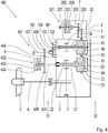
- the Fig. 1 shows the structure of a marine gear 100 with a main drive shaft 1 which can be connected to a main drive motor.
- the marine transmission 100 further comprises an output shaft 2 which is connected to a propeller shaft 4.
- a propeller 5 is attached to the free end of the propeller shaft 4.
- the propeller 5 is designed as a fixed propeller.
- the marine transmission 100 also has a main housing 6 and a secondary housing 7.
- the marine transmission 100 has a first multi-plate clutch 10 and a second multi-plate clutch 20, as well as a first pinion shaft 11 and a second pinion shaft 21.
- the two multi-plate clutches 10, 20 and the two pinion shafts 11, 21 are arranged and supported in the main housing 6.
- the first pinion shaft 11 and the second pinion shaft 21 are arranged in parallel to each other.
- the first Multi-disc clutch 10 is arranged coaxially with the first pinion shaft 11 and the second multi-disc clutch 20 is arranged coaxially with the second pinion shaft 21.
- Both pinion shafts 11, 21 are designed as hollow shafts in this embodiment.
- the main drive shaft 1 is arranged parallel to the first pinion shaft 11 and is mounted in the secondary housing 7 of the marine gear 100.
- the first and second multi-plate clutches 10, 20 each include an outer plate carrier 13, 23 and an inner plate carrier 14, 24.
- the outer plate carrier 13, 23 of each multi-plate clutch 10, 20 is arranged coaxially to the respective inner plate carrier 14, 24.
- the outer disc carrier 13, 23 of each multi-disc clutch 10, 20 is at least approximately cup-shaped and encloses the respective inner disc carrier 14, 24.
- Each outer disc carrier 13, 23 carries a plurality of outer discs with friction surfaces on its inside.
- Each inner disk carrier 14, 24 carries a plurality of inner disks with friction surfaces.
- the associated outer disk carrier 13, 23 is coupled to the associated inner disk carrier 14, 24.
- the outer disks and the inner disks are pressed against one another so that a torque can be transmitted by frictional engagement.
- the first inner plate carrier 14 of the first multi-plate clutch 10 is connected in a rotationally fixed manner to the first pinion shaft 11, and the second inner plate carrier 24 of the second multi-plate clutch 20 is connected in a rotationally fixed manner to the second pinion shaft 21.
- a first output pinion 12 is arranged on the first pinion shaft 11 in a rotationally fixed manner and a second output pinion 22 is arranged in a rotationally fixed manner on the second pinion shaft 21.
- the first output pinion 12 and the second output pinion 22 are in engagement with an output gear 3 arranged on the output shaft 2 so as to be fixed against rotation.
- the engagement of the first output pinion 12 with the output gear 3 cannot be seen because here both pinion shafts 11, 21 have been folded into the plane of the drawing.
- the two pinion shafts 11, 21 lie in vertical planes one behind the other, so that the simultaneous engagement of the two output pinions 12 and 22 with the output gear 3 is given.
- the two multi-disk clutches 10, 20 cooperate with the main drive shaft 1 and the output shaft 2 in such a way that the drive power for selecting the direction of rotation of the output shaft 2 is selectively transmitted via the closed first multi-disk clutch 10 to the first pinion shaft 11 or via the closed second multi-disk clutch 20 to the second Pinion shaft 21 is transferable.
- Such gears that are permanently in engagement with one another are also called constant gears.
- the main drive shaft 1 and the output shaft 2 are arranged parallel to one another.
- Such a coaxial drive and output is advantageous with regard to space requirements, the position of the center of gravity or the possibility of laying the foundation for the ship's gearbox and the entire drive train in the ship's hull.
- the main drive shaft 1 protrudes from the secondary housing 7 on a drive side 30, while the output shaft 2 protrudes from the main housing 6 on an output side 31 opposite the drive side 30.
- the secondary housing 7 is arranged in the radial direction on the main housing 6 in relation to the axis of rotation of the main drive shaft 1 such that the secondary housing 7 does not extend beyond the main housing 6 in the axial direction.
- the axial dimensions of the entire marine gear 100 can thus be kept relatively small in order to keep the required installation space small in the axial direction.
- the axial and radial directions in this document are based on the alignment of the main drive shaft 1, unless expressly stated otherwise.
- the marine transmission 100 has a first power take-off 101 which drives a pump 105 via a first power take-off shaft 102 and a first pair of spur gears 103.
- the pump 105 is arranged on the output side 31 of the marine gear 100.
- the first pair of spur gears 103 is arranged in a further secondary housing 9, which is fastened to the main housing 6 on the output side 31.
- the first power take-off shaft 102 is non-rotatably connected to the outer disk carrier 13 of the first disk clutch 10 and is arranged coaxially to this and to the first pinion shaft 11.
- the first power take-off shaft 102 runs through the first pinion shaft 11 designed as a hollow shaft. Since the pump 105 is permanently coupled to the main drive shaft 1 via a first power take-off output shaft 104, the first spur gear pair 103, the first power take-off shaft 102 and the first outer disk carrier 13, the pump 105 is a primary pump.
- the same basic structure means that each of the marine gears 100, 200, 300 and 400 have a main drive shaft 1, an output shaft 2, a first multi-disc clutch 10 and a second multi-disc clutch 20, as well as a first pinion shaft 11 and a second pinion shaft 21, each in one Main housing 6 and a secondary housing 7 are arranged and supported.
- Same elements are in the Fig. 2 , 3 and 4th therefore denoted by the same reference numerals and not described in more detail here, provided that their arrangement in the respective marine transmission does not differ from the arrangement in the marine transmission 100 according to FIG Fig. 1 differs.
- the marine gears 200, 300 and 400 differ from the marine gear 100 in the type and arrangement of the respective power take-offs or a shaft brake.
- the marine transmission 200 shown has a second power take-off 201 in addition to the components of the marine transmission 100.
- the second power take-off 201 can be driven via a second pair of spur gears 206 and a second power take-off shaft 205.
- the second power take-off 201 is arranged parallel to the main drive shaft 1 in the secondary housing 7. This means that the second power take-off shaft 205 is supported in the secondary housing 7 and is arranged parallel to the main drive shaft 1.
- the second power take-off 201 is designed as an engine-independent or switchable power take-off. It therefore includes a switchable clutch, namely the third multi-disk clutch 202.
- the second power take-off 201 can be coupled to the main drive shaft 1 or separated from it.
- the third multi-plate clutch 202 is arranged coaxially to the second power take-off shaft 205.
- a third inner disc carrier 203 of the third multi-disc clutch 202 is connected to the second power take-off shaft 205 in a rotationally fixed manner, while a third outer disc carrier 204 is connected to a second power take-off output shaft 207 in a rotationally fixed manner.
- the second power take-off output shaft 207 protrudes from the secondary housing 7 on the output side 31 in order to drive a power take-off unit there, for example a shaft generator.
- a suitable and advantageous speed of the second power take-off 201 can be set for the respective power take-off unit in relation to an operating speed of the main drive motor.
- the marine gear 300 shown has a shaft brake 301 in addition to the components of the marine gear 200.
- the shaft brake 301 is coaxial arranged to the second pinion shaft 21.
- the shaft brake 301 comprises a fourth outer disk carrier 302 and a fourth inner disk carrier 303.
- the fourth inner disk carrier 303 is connected to the second pinion shaft 21 in a rotationally fixed manner, while the fourth outer disk carrier 302 is fixed to the housing, i.e. it is attached to the main housing 6.
- the fourth outer disk carrier 302 and the fourth inner disk carrier 303 each have brake disks with friction surfaces which are pressed against one another to brake the second pinion shaft 21, the output shaft 2 and the propeller shaft 4.
- the shaft brake 301 can be actuated hydraulically, for example.
- the marine transmission 400 shown has a third power take-off 401 in addition to the components of the marine transmission 200.
- the third power take-off 401 can be driven via a third power take-off shaft 405 connected to the second pinion shaft 21 in a rotationally fixed manner.
- the third power take-off 401 is designed as a switchable power take-off. It therefore includes a switchable clutch, namely the fourth multi-plate clutch 402. With the fourth multi-plate clutch 402, the third power take-off 401 can be coupled to the second pinion shaft 21 or separated from it.
- the fourth multi-plate clutch 402 is arranged coaxially with the second pinion shaft 21.
- a fourth outer disc carrier 404 of the fourth multi-disc clutch 402 is connected to the third power take-off shaft 405 in a rotationally fixed manner, while a fourth inner disc carrier 403 is rotationally fixedly connected to a driving spur gear 408 of a third spur gear pair 406.
- a driven spur gear 409 of the third pair of spur gears 406 is in engagement with the driving spur gear 408.
- the driven spur gear 409 is attached to the third power take-off output shaft 407 in a rotationally fixed manner.
- the third power take-off 401 is arranged on the output side 31 of the marine gear 400. At least the essential components of the third power take-off 401 can also be arranged in a further secondary housing, so that, for example, only the third power take-off output shaft 407 protrudes from the still further secondary housing on the output side 31 of the marine gear 400.
- the present invention is not restricted to the illustrated and described exemplary embodiments. Modifications are within the scope of the claims just as possible as a combination of the features, even if these are shown and described in different exemplary embodiments.
- the power take-offs 32, 201, 401 and the shaft brake 301 shown in the figures can be arranged in all possible configurations on the ship's transmission in the sense of a modular system.
- marine transmissions are also possible that have only one power take-off, the only power take-off being designed as described above as a second or third power take-off.
- a shaft brake in each of these configurations can be arranged on different shafts of the marine gear.
Description
- Die Erfindung betrifft ein Schiffsgetriebe nach dem Oberbegriff des Anspruches 1.
- Ein derartiges Schiffsgetriebe übersetzt eine Eingangsdrehzahl in eine Ausgangsdrehzahl und kann in vielen Fällen auch eine Drehrichtungsumkehr der mit der Abtriebswelle des Schiffsgetriebes verbundenen Propellerwelle ermöglichen. Ein solches Schiffsgetriebe kann für eine Antriebsanlage für ein Schiff oder ein Boot genutzt werden.
- Bei Schiffen für kommerzielle Anwendungen, beispielsweise bei Fischereischiffen, sind Propellerdrehzahlen von 140 - 170 U/min üblich, wegen des guten mechanischhydraulischen Wirkungsgrades. Dabei werden gewöhnlich langsam laufende oder mittelschnell laufende Dieselmotoren zum Antrieb genutzt, die am Motorabtrieb eine Drehzahl von 100 bis 1000 Umdrehungen pro Minute zur Verfügung stellen. Erforderlichenfalls wird diese Drehzahl mittels eines Schiffsgetriebes mit Übersetzungen bis maximal 6:1 übersetzt, um die genannten Propellerdrehzahlen zu erreichen.
- Ein solches Schiffsgetriebe mit einem Grundgetriebe und einer schaltbaren Nebenabtriebs-Einheit ist aus der
DE 10 2012 218 912 A1 bekannt. Dieses Schiffsgetriebe weist eine Hauptantriebswelle auf, die mittels einer ersten lastschaltbaren Kupplung mit einer ersten Ritzelwelle verbindbar ist. Die Hauptantriebswelle, die erste lastschaltbare Kupplung und die erste Ritzelwelle sind dabei koaxial zueinander angeordnet und in einem Getriebegehäuse gelagert. - Aus der
CN 103 322 133 A ist ein Schiffsgetriebe mit einer Hauptantriebswelle, mit einer ersten und einer zweiten Lamellenkupplung, mit einer ersten und einer zweiten Ritzelwelle und mit einer Abtriebswelle bekannt. Eine Antriebsleistung kann dabei von der Hauptantriebswelle über die erste Lamellenkupplung und die erste Ritzelwelle auf die Abtriebswelle übertragen werden. Die beiden Lamellenkupplungen, die beiden Ritzelwellen und die Abtriebswelle sind dabei teilweise in einem ersten Gehäuseteil des Schiffsgetriebes gelagert. Die Hauptantriebswelle ist parallel zu der ersten und zweiten Ritzelwelle angeordnet und in einem zweiten Gehäuseteil des Schiffsgetriebes gelagert. Im Betrieb wirken die erste und die zweite Lamellenkupplung sowie die erste und die zweite Ritzelwelle derart mit der Hauptantriebswelle und der Abtriebswelle zusammen, dass zur Auswahl der Drehrichtung der Abtriebswelle die Antriebsleistung wahlweise über die geschlossene erste Lamellenkupplung auf die erste Ritzelwelle oder über die geschlossene zweite Lamellenkupplung auf die zweite Ritzelwelle übertragen wird. Durch das gezielte Schließen jeweils einer der beiden Lamellenkupplungen wird also zwischen Vorwärts- und Rückwärtsantrieb ausgewählt. Ein Außenlamellenträger der ersten Lamellenkupplung weist eine erste Außenverzahnung auf, die mit einem Antriebsritzel auf der Hauptantriebswelle im Eingriff steht, während ein Innenlamellenträger der ersten Lamellenkupplung mit der ersten Ritzelwelle verdrehfest verbunden ist. Ein zweiter Außenlamellenträger der zweiten Lamellenkupplung weist eine zweite Außenverzahnung aufweist, die dauernd mit der ersten Außenverzahnung des ersten Außenlamellenträgers im Eingriff steht. Der Innenlamellenträger der zweiten Lamellenkupplung ist mit der zweiten Ritzelwelle verdrehfest verbunden. - Es ist die Aufgabe der vorliegenden Erfindung ein Schiffsgetriebe zu schaffen, das in einem breiten Anwendungsbereich flexibel einsetzbar und kostengünstig herstellbar ist.
- Diese Aufgabe wird gelöst durch Schiffsgetriebe mit den Merkmalen des Anspruchs 1. Vorteilhafte Ausführungen sind in den abhängigen Ansprüchen angegeben.
- Demnach wird ein Schiffsgetriebe mit einer mit einem Hauptantriebsmotor verbindbaren Hauptantriebswelle, mit zumindest einer ersten Lamellenkupplung und einer zweiten Lamellenkupplung, mit zumindest einer ersten Ritzelwelle und einer zweiten Ritzelwelle, und mit einer Abtriebswelle vorgeschlagen. Die Antriebsleistung des Hauptantriebsmotors ist dabei von der Hauptantriebswelle zumindest über die erste Lamellenkupplung und die erste Ritzelwelle auf die Abtriebswelle übertragbar. Die Antriebsleistung kann, abhängig von der Getriebeausführung und Schaltstellung auch noch über weitere Elemente des Antriebsstrangs in dem Schiffsgetriebes geleitet werden. Die erste Lamellenkupplung, die erste Ritzelwelle und die Abtriebswelle sind dabei in einem Hauptgehäuse des Schiffsgetriebes gelagert.
- Die Hauptantriebswelle ist erfindungsgemäß parallel zu der ersten Ritzelwelle angeordnet und in einem Nebengehäuse des Schiffsgetriebes gelagert. Die Lagerung der Hauptantriebswelle kann in bekannter Weise mittels Wälzlagern realisiert werden, wobei sich die Wälzlager an geeigneten Lagerstellen des Nebengehäuses abstützen. Entsprechende Wälzlager und Lagerstellen sind in dem Hauptgehäuse für die zumindest eine Lamellenkupplung, die zumindest eine Ritzelwelle und die Abtriebswelle vorgesehen. Die Hauptantriebswelle kann zumindest größtenteils in dem Nebengehäuse angeordnet sein, sodass beispielsweise nur das antriebsseitige Ende der Hauptantriebswelle aus dem Nebengehäuse hinausragt, um dort unmittelbar oder über eine Gelenkwelle mit einer Motorwelle des Hauptantriebsmotors verbunden zu werden. Die Hauptantriebswelle kann dazu an ihrem antriebsseitigen Ende einen Antriebsflansch aufweisen, über den sie reibschlüssig oder formschlüssig mit der Gelenkwelle oder der Motorwelle des Hauptantriebsmotors verbindbar ist.
- Die Anordnung und Lagerung der Hauptantriebswelle in dem Nebengehäuse parallel zu der ersten Ritzelwelle ermöglicht es, zwischen der Hauptantriebswelle und der ersten Ritzelwelle eine zusätzliche Übersetzungsstufe vorzusehen, beispielsweise in Form einer Stirnradstufe. Verglichen mit den herkömmlichen Schiffsgetrieben können dadurch verhältnismäßig große Übersetzungen von bis zu 15 : 1 realisiert werden. Durch solche größere Übersetzungen ist es möglich, die eingangs genannten optimalen Propellerdrehzahlen von 140 - 170 U/min auch mit schnelllaufenden Motoren zu realisieren. Die Verwendung von schnelllaufenden Motoren eröffnet bei der Entwicklung und beim Bau eines Schiffs und dessen Antriebsstrangs beispielsweise die Möglichkeit den Bauraum in einem Schiffsrumpf anders zu nutzen. Ferner kann auf eine größere Anzahl an möglichen Herstellern und Zulieferern auch von schnelllaufenden Schiffsmotoren zugegriffen werden.
- Ein anderer vorteilhafter Aspekt der Erfindung ist, dass größere Übersetzungen möglich sind, unter Verwendung von bereits bestehenden und bewährten Standardkomponenten, beispielsweise des Hauptgehäuses und des Nebengehäuses. Aufwändige, teure und zeitraubende Neukonstruktionen können damit verhindert werden, ebenso wie eine große und teure Variantenvielfalt. Investitionen in Werkzeuge, Montage- und Prüfeinrichtungen sind nicht erforderlich, die Anzahl notwendiger Neuteile ist sehr gering.
- Für das Hauptgehäuse wird ein Hauptgehäuse verwendet, wie es auch in herkömmlichen Schiffsgetrieben genutzt wird, bei denen die Hauptantriebswelle in dem Hauptgehäuse angeordnet und gelagert ist. Die Gehäuseöffnung in dem Hauptgehäuse, die beim herkömmlichen Schiffsgetriebe zur Durchführung der Hauptantriebswelle vorgesehen war, kann mit einem einfachen Deckel verschlossen werden. Als Nebengehäuse wird ein Nebengehäuse genutzt wie es bei herkömmlichen Schiffsgetrieben für einen Nebenabtrieb vorgesehen ist. Durch die zusätzliche Übersetzungsstufe wird die Hauptantriebswelle mit höheren Drehzahlen angetrieben, sodass sich die Drehmomente an der Hauptantriebswelle entsprechend verringern. Deshalb können die Lager- bzw. Abstützkräfte an den Lagerstellen und am Nebengehäuse auch von dem ursprünglich nur für einen Nebenabtrieb konstruierten Nebengehäuse aufgenommen werden.
- Mithilfe der Erfindung kann der Hauptantriebsmotor ausgetauscht werden, ohne Änderung der Getriebe-Fundamentierung im Schiff vornehmen zu müssen. Dabei kann beispielsweise von einem mittelschnelllaufenden auf einen schnelllaufenden Dieselmotor oder umgekehrt gewechselt werden. Die Getriebe-Fundamentierung ist in der Regel nur mit dem Hauptgehäuse verbunden, dessen Verbindungsstellen zur Fundamentierung wegen der Weiterverwendung desselben Hauptgehäuses unverändert bleiben können.
- Der Begriff Lamellenkupplung soll jede Art von reibschlüssiger Kupplung umfassen. Jede der beiden Lamellenkupplungen kann also als lastschaltbare Kupplung, insbesondere als Reibscheibenkupplung ausgeführt sein. Eine solche Lamellenkupplung kann insbesondere hydraulisch betätigbar sein. Denkbar sind jedoch auch andere Betätigungsarten, beispielsweise pneumatisch oder elektrisch.
- Die Abtriebswelle kann unmittelbar oder über weitere Antriebsstrangelemente mit der Propellerwelle eines anzutreibenden Schiffes drehmomentübertragend verbunden werden.
- Gemäß der Erfindung dient das Hauptgehäuse zum Aufnehmen und Lagern der ersten Lamellenkupplung, der ersten Ritzelwelle und der Abtriebswelle. Das Schiffsgetriebe wird mittels des Hauptgehäuses in einem Schiffrumpf befestigt, sodass zumindest der überwiegende Anteil an Kräften und Drehmomenten des Schiffsgetriebes über das Hauptgehäuse in dem Schiffsrumpf abgestützt werden können.
- Ein Schiffsgetriebe mit lediglich einer ersten Lamellenkupplung und einer Ritzelwelle ist ausreichend und geeignet die Propellerwelle in einer Richtung anzutreiben. Um mit einem derartigen Schiffsantrieb die Fahrtrichtung des Schiffs von vorwärts auf rückwärts umzukehren, kann ein Verstellpropeller eingesetzt werden. Ein Verstellpropeller ermöglicht es, durch Verdrehen der Flügel in der Nabe, die Steigung der Flügel während der Fahrt zu ändern und umzukehren. Der Verstellpropeller ermöglicht damit eine Rückwärtsfahrt bei unveränderter Drehrichtung des Hauptantriebsmotors und der Propellerwelle, nämlich dadurch, dass eine negative Steigung an dem Verstellpropeller eingestellt wird.
- Für Schiffsantriebe mit einem Festpropeller ist dagegen gemäß der Erfindung vorgesehen, dass das Schiffsgetriebe eine erste und eine zweite Lamellenkupplung sowie eine erste und eine zweite Ritzelwelle aufweist. Diese wirken derart mit der Hauptantriebswelle und der Abtriebswelle zusammen, dass die Antriebsleistung zur Auswahl der Drehrichtung der Abtriebswelle wahlweise über die geschlossene erste Lamellenkupplung auf die erste Ritzelwelle oder über die geschlossene zweite Lamellenkupplung auf die zweite Ritzelwelle übertragbar ist. Mit anderen Worten wird zum Umschalten von Vorwärtsfahrt auf Rückwärtsfahrt und umgekehrt jeweils eine der beiden Lamellenkupplungen geöffnet und die andere geschlossen. Sind beide Lamellenkupplungen geöffnet, so ist die triebliche Verbindung zwischen Hauptantriebswelle und Abtriebswelle unterbrochen. Dieser Zustand kann auch als Leerlauf- oder Neutralstellung bezeichnet werden.
- Gemäß der Erfindung sind die erste Ritzelwelle und die zweite Ritzelwelle parallel zueinander angeordnet, dass auf der ersten Ritzelwelle ein erstes Abtriebsritzel und auf der zweiten Ritzelwelle ein zweites Abtriebsritzel jeweils verdrehfest angeordnet sind, und dass das erste Abtriebsritzel und das zweite Abtriebsritzel mit einem auf der Abtriebswelle verdrehfest angeordneten Abtriebszahnrad im Eingriff stehen. Die Formulierung, wonach zwei Elemente verdrehfest zueinander angeordnet sind, ist so zu verstehen, dass die beiden Elemente in Bezug auf eine Rotationsachse nicht gegeneinander verdreht werden können. Eine verdrehfeste Verbindung kann beispielsweise in Form eines Pressverbands ausgeführt werden. Auch andere reib- oder formschlüssige Wellen-Naben-Verbindungen können als verdrehfeste Verbindung eingesetzt werden. Der Begriff "verdrehfest" kann jedoch auch bedeuten, dass zwei verdrehfest zueinander angeordnete Elemente aus einem Stück gefertigt, also einstückig ausgeführt sind. Beispielsweise kann ein verdrehfest auf einer Welle angeordnetes Zahnrad oder Ritzel zusammen mit der genannten Welle aus einem Stück hergestellt sein.
- Gemäß der Erfindung umfassen die erste und die zweite Lamellenkupplung jeweils einen Außenlamellenträger und einen Innenlamellenträger, die zum Schließen der Kupplung miteinander gekoppelt werden. Der Außenlamellenträger und der Innenlamellenträger jeder Lamellenkupplung können dabei koaxial zueinander angeordnet sein.
- Der erste Außenlamellenträger der ersten Lamellenkupplung weist eine erste Außenverzahnung auf, die mit einem Antriebsritzel auf der Hauptantriebswelle im Eingriff steht, während ein erster Innenlamellenträger der ersten Lamellenkupplung mit der ersten Ritzelwelle verdrehfest verbunden ist. Die erste Außenverzahnung und das damit kämmende Antriebsritzel auf der Hauptantriebswelle bilden dabei die oben beschriebene zusätzliche Übersetzungsstufe, die es ermöglicht auch mit schnelllaufenden Motoren optimale Propellerdrehzahlen zu realisieren. Durch eine gezielte Auswahl der Parameter dieser Stirnradpaarung, kann abhängig von der optimalen Betriebsdrehzahl des jeweils vorgesehenen Hauptantriebsmotors eine geeignete Übersetzung berechnet und eingesetzt werden, um für jede Anwendung die optimale Propellerdrehzahl zu erhalten.
- Ein zweiter Außenlamellenträger der zweiten Lamellenkupplung weist eine zweite Außenverzahnung auf, die dauernd mit der ersten Außenverzahnung des ersten Außenlamellenträgers im Eingriff steht. Ein zweiter Innenlamellenträger der zweiten Lamellenkupplung ist mit der zweiten Ritzelwelle verdrehfest verbunden.
- Insofern bildet jeweils der Außenlamellenträger mit seiner Außenverzahnung ein separat rotierbares Bauteil, während der Innenlamellenträger dauernd mit der zugeordneten Ritzelwelle fest verbunden ist. Der Außenlamellenträger kann ferner verdrehfest mit einer Kupplungswelle verbunden sein, wobei die Kupplungswelle insbesondere der Abstützung und Lagerung des Außenlamellenträgers in dem Hauptgehäuse dient. Die Kupplungswelle kann beispielsweise mittels eines oder mehrerer Wälzlager in dem Hauptgehäuse gelagert sein.
- Eine solche Kupplungswelle kann beispielsweise als Vollwelle ausgeführt sein, die verdrehfest mit dem Außenlamellenträger verbunden ist. Die koaxial zu der Kupplungswelle angeordnete Ritzelwelle kann dabei als Hohlwelle ausgeführt sein, sodass die Kupplungswelle durch die Ritzelwelle hindurch verläuft. Die Kupplungswelle ist dabei also in der als Hohlwelle ausgeführten Ritzelwelle rotierbar angeordnet. Solche Verbindungen und Anordnungen der Lamellenträger, Kupplungswellen und Ritzelwellen haben sich in herkömmlichen Schiffsgetrieben im Betrieb als dauerhaft und zuverlässig erwiesen und können daher auch in Verbindung mit der vorliegenden Erfindung vorteilhaft genutzt werden.
- Die bereits oben beschriebene Verwendung von Standardteilen kann auch im Hinblick auf die Elemente der Lamellenkupplungen und Ritzelwellen vorteilhaft angewendet werden. Die mehrfache Verwendung von Standardteilen wird auch Gleichteilekonzept genannt. Entsprechend einem Gleichteilekonzept und/oder einer Gleichteileverwendung kann eine Mehrzahl von Komponenten aus gleichen Teilen aufgebaut sein. Unter gleichen Teilen oder Komponenten kann insbesondere verstanden werden, dass die Außenlamellenträger der Lamellenkupplungen eine in einem Toleranzbereich gleiche und/oder identische Geometrie aufweisen. Unter gleichen Teilen kann insbesondere verstanden werden, dass ein Außenlamellenträger und/oder ein Innenlamellenträger einer Lamellenkupplung funktional auch als Außenlamellenträger bzw. Innenlamellenträger für eine weitere Lamellenkupplung verwendet werden kann. Entsprechendes gilt auch für die beiden Ritzelwellen.
- Ein weiterer Aspekt der Erfindung betrifft eine vorteilhafte Ausrichtung und Anordnung der Hauptantriebswelle und der Abtriebswelle des Schiffsgetriebes. Demgemäß kann vorgesehen sein, dass die Hauptantriebswelle und die Abtriebswelle parallel zueinander angeordnet sind, dass die Hauptantriebswelle zu einer Antriebsseite hin aus dem Nebengehäuse herausragt, und dass die Abtriebswelle zu einer der Antriebsseite entgegengesetzten Abtriebsseite hin aus dem Hauptgehäuse herausragt.
- Der überwiegende Teil der Hauptantriebswelle ist demgemäß im Inneren des Nebengehäuses angeordnet, während ein Endbereich der Hauptantriebswelle auf der Antriebsseite aus dem Nebengehäuse hinaus ragt. An diesem Endbereich kann ein Antriebsflansch befestigt sein, zur Verbindung der Hauptantriebswelle mit der Motorwelle des Hauptantriebsmotors.
- Der überwiegende Teil der Abtriebswelle und das verdrehfest auf der Abtriebswelle angeordnete Abtriebszahnrad sind in dem Hauptgehäuse angeordnet, während ein Endbereich der Abtriebswelle auf der Abtriebsseite aus dem Hauptgehäuse hinausragt. Eine solche Ausrichtung der Hauptantriebswelle und der Abtriebswelle ermöglicht eine vorteilhafte Anordnung des Schiffsgetriebes in einem Schiffsrumpf im Hinblick auf eine optimale Nutzung des vorhandenen Bauraums.
- Gemäß einer weiteren bevorzugten Ausführung kann das Nebengehäuse an dem Hauptgehäuse angeordnet sein, dass sich das Nebengehäuse in axialer Richtung nicht über das Hauptgehäuse hinaus erstreckt. Das Nebengehäuse kann demnach die Abmessungen des Schiffsgetriebes in radialer Richtung vergrößern, nicht aber in axialer Richtung. Auch dieses Merkmal dient einem kompakten Aufbau und einer bauraumsparenden Anordnung des Schiffsgetriebes im Schiffsrumpf.
- Gemäß der Erfindung weist das Schiffsgetriebe zumindest einen Nebenantrieb oder einen Nebenabtrieb auf. Als Nebenantrieb kann beispielsweise ein im Vergleich zum Hauptantriebsmotor kleinerer Verbrennungsmotor oder ein Elektromotor vorgesehen werden. Nebenabtriebe werden auch PTO (Power Take Off) genannt. Über einen solchen Nebenabtrieb können beispielsweise Pumpen oder Generatoren angetrieben werden, die für den Schiffsbetrieb benötigt werden. Nebenantriebe und Nebenabtriebe können zuschaltbar ausgeführt sein, sodass sie unabhängig vom Betrieb des Hauptantriebsmotors betrieben werden können. Auch motorabhängige Nebenabtriebe sind möglich. Ein motorabhängiger Nebenabtrieb ist dauernd mit der Hauptantriebswelle gekoppelt. Er wird daher immer angetrieben, solange der Hauptantriebsmotor läuft. Ein motorabhängiger Nebenantrieb für eine Pumpe wird auch Primärpumpenantrieb genannt.
- Der oder die Nebenantriebe bzw. Nebenabtriebe können jeweils an verschiedenen Wellen des Schiffsgetriebes angekoppelt sein. Gemäß einer Ausführungsform kann der zumindest eine Nebenantrieb und/oder Nebenabtrieb mittels einer dritten Lamellenkupplung zuschaltbar sein. Somit handelt es sich bei einem solchen Nebenabtrieb um einen motorunabhängigen Nebenabtrieb.
- Bevorzugt kann beispielsweise vorgesehen sein, dass ein motorabhängiger Nebenantrieb für eine Primärpumpe koaxial zu der ersten Lamellenkupplung und der ersten Ritzelwelle angeordnet ist, während ein motorunabhängiger Pumpenantrieb koaxial zu der zweiten Ritzelwelle angeordnet ist.
- Eine oben beschriebene, als Vollwelle ausgeführte Kupplungswelle kann zur Ankopplung von einem oder mehreren Nebenabtrieben genutzt werden, beispielsweise zum Antreiben einer Primärpumpe. Eine als Vollwelle ausgebildete Kupplungswelle kann sich von der Antriebsseite des Schiffsgetriebes bis zur Abtriebsseite erstrecken, wobei dann am abtriebsseitigen Ende der Kupplungswelle ein Nebenabtrieb angekoppelt werden kann.
- Andere bzw. weitere Nebenabtriebe können an der zweiten Ritzelwelle angeordnet und angekoppelt sein. Da die zweite Ritzelwelle nicht permanent mit der Hauptantriebswelle und damit mit dem Hauptantriebsmotor des Schiffes verbunden ist, handelt es sich bei einem an der zweiten Ritzelwelle angeordneten Nebenabtrieb um einen motorunabhängigen Nebenabtrieb. Dahingegen ist die zweite Ritzelwelle über deren Abtriebsritzel und das Abtriebszahnrad permanent mit der Abtriebswelle gekoppelt. Ein von der Abtriebswelle antreibbarer Nebenabtrieb wird auch Sekundärabtrieb genannt. Ein Sekundärabtrieb eignet sich beispielsweise zum Betreiben einer Schleppfahrtpumpe.
- An der ersten oder der zweiten Ritzelwelle kann auch eine Wellenbremse angekoppelt werden, mit der die Abtriebswelle und damit die Propellerwelle festgehalten werden kann. Verschiedene Ausführungsformen und die Funktion einer Wellenbremse sind dem Fachmann bekannt.
- Gemäß der vorliegenden Erfindung ist vorgesehen, dass der Nebenabtrieb oder Nebenantrieb koaxial oder parallel zu der Hauptantriebswelle in dem Nebengehäuse angeordnet ist. In diesem Fall kann also die Hauptantriebswelle und eine Nebenantriebswelle oder eine Nebenabtriebswelle in dem Nebengehäuse gelagert sein.
- Die primärseitige Ankopplung eines Nebenabtriebs ist für solche Anwendungen vorteilhaft, die eine höhere Drehzahl eines schnell- oder mittelschnelllaufenden Schiffsmotors zum Antreiben des jeweiligen Aggregates benötigen. Erforderlichenfalls kann dazu die Drehzahl der Hauptantriebswelle durch eine Stirnradstufe auf eine parallel zu der Hauptantriebswelle angeordnete Nebenabtriebswelle erhöht werden. Beispielsweise benötigen viele Pumpenarten eine höhere Drehzahl, als die vom Schiffsmotor über die Hauptantriebswelle bereitgestellte Drehzahl. Wellengeneratoren, die auf Schiffen der Versorgung mit elektrischer Energie dienen, können vorteilhaft mit einer Drehzahl von 1500 oder 1800 Umdrehungen pro Minute angetrieben werden. Solche Drehzahlen können über eine Stirnradstufe mit entsprechendem Übersetzungsverhältnis ins Schnelle zwischen der Hauptantriebswelle und der Nebenabtriebswelle einfach realisiert werden. Eine derartige Anpassung der Übersetzung eines Nebenabtriebs kann im Rahmen eines sogenannten Baukastensystems oder einer Modulbauweise erfolgen, bei der eine begrenzte Auswahl an Komponenten zur Verfügung steht, die je nach Anwendungsbedingungen und Anforderungen ausgewählt und zu einem für den jeweiligen Anwendungsfall geeigneten Schiffsgetriebe mit Nebenabtrieb zusammengebaut werden können. Ein solches Baukastensystem kann durch die Verwendung von Standardkomponenten Produktionskosten und Lagerhaltungskosten für Schiffsgetriebe und deren Bauteile verringern, ohne die Funktionalität einzuschränken.
- Im Folgenden wird die Erfindung mit weiteren vorteilhaften Merkmalen anhand von in den nachfolgenden Figuren abgebildeten Ausführungsbeispielen näher erläutert.
- Dabei zeigt die
- Fig. 1
- eine schematische Darstellung eines ersten Schiffsgetriebes;
- Fig. 2
- eine schematische Darstellung eines ersten erfindungsgemäßen Schiffsgetriebes;
- Fig. 3
- eine schematische Darstellung eines zweiten erfindungsgemäßen Schiffsgetriebes und
- Fig. 4
- eine schematische Darstellung eines dritten erfindungsgemäßen Schiffsgetriebes.
- Die
Fig. 1 zeigt den Aufbau eines Schiffsgetriebes 100 mit einer Hauptantriebswelle 1, die mit einem Hauptantriebsmotor verbindbar ist. Das Schiffsgetriebe 100 umfasst ferner eine Abtriebswelle 2, die mit einer Propellerwelle 4 verbunden ist. Auf dem freien Ende der Propellerwelle 4 ist ein Propeller 5 befestigt. Der Propeller 5 ist als Festpropeller ausgeführt. Das Schiffsgetriebe 100 weist ferner ein Hauptgehäuse 6 und ein Nebengehäuse 7 auf. - Das Schiffsgetriebe 100 weist eine erste Lamellenkupplung 10 und eine zweite Lamellenkupplung 20, sowie eine erste Ritzelwelle 11 und eine zweite Ritzelwelle 21 auf. Die beiden Lamellenkupplungen 10, 20 und die beiden Ritzelwellen 11, 21 sind in dem Hauptgehäuse 6 angeordnet und gelagert. Die erste Ritzelwelle 11 und die zweite Ritzelwelle 21 sind parallel zueinander angeordnet. Die erste Lamellenkupplung 10 ist koaxial zu der ersten Ritzelwelle 11 angeordnet und die zweite Lamellenkupplung 20 ist koaxial zu der zweiten Ritzelwelle 21 angeordnet. Beide Ritzelwellen 11, 21 sind in diesem Ausführungsbeispiel als Hohlwellen ausgeführt. Die Hauptantriebswelle 1 ist parallel zu der ersten Ritzelwelle 11 angeordnet und in dem Nebengehäuse 7 des Schiffsgetriebes 100 gelagert.
- Die erste und die zweite Lamellenkupplung 10, 20 umfassen jeweils einen Außenlamellenträger 13, 23 und einen Innenlamellenträger 14, 24. Der Außenlamellenträger 13, 23 jeder Lamellenkupplung 10, 20 ist koaxial zu dem jeweiligen Innenlamellenträger 14, 24 angeordnet. Der Außenlamellenträger 13, 23 jeder Lamellenkupplung 10, 20 ist zumindest annähernd topfförmig ausgestaltet und umschließt den jeweiligen Innenlamellenträger 14, 24. Jeder Außenlamellenträger 13, 23 trägt auf seiner Innenseite eine Mehrzahl an Außenlamellen mit Reibflächen. Jeder Innenlamellenträger 14, 24 trägt eine Mehrzahl von Innenlamellen mit Reibflächen. Zum Schließen der jeweiligen Lamellenkupplung 10, 20 wird der zugehörige Außenlamellenträger 13, 23 mit dem zugehörigen Innenlamellenträger 14, 24 gekoppelt. Dazu werden die Außenlamellen und die Innenlamellen aufeinander gepresst, sodass durch Reibschluß ein Drehmoment übertragbar ist.
- Der erste Innenlamellenträger 14 der ersten Lamellenkupplung 10 ist mit der ersten Ritzelwelle 11 verdrehfest verbunden und der zweite Innenlamellenträger 24 der zweiten Lamellenkupplung 20 ist mit der zweiten Ritzelwelle 21 verdrehfest verbunden.
- Auf der ersten Ritzelwelle 11 ist ein erstes Abtriebsritzel 12 verdrehfest angeordnet und auf der zweiten Ritzelwelle 21 ist ein zweites Abtriebsritzel 22 verdrehfest angeordnet. Das erste Abtriebsritzel 12 und das zweite Abtriebsritzel 22 stehen im Eingriff mit einem auf der Abtriebswelle 2 verdrehfest angeordneten Abtriebszahnrad 3. In der schematischen Darstellung der
Fig. 1 ist der Eingriff des ersten Abtriebsritzels 12 mit dem Abtriebszahnrad 3 nicht erkennbar, weil hier beide Ritzelwellen 11, 21 in die Zeichnungsebene geklappt wurden. In der praktischen Ausführung liegen die beiden Ritzelwellen 11, 21 jedoch in hintereinanderliegenden Vertikalebenen, sodass der gleichzeitige Eingriff der beiden Abtriebsritzel 12 und 22 mit dem Abtriebszahnrad 3 gegeben ist. - Die beiden Lamellenkupplungen 10, 20 wirken derart mit der Hauptantriebswelle 1 und der Abtriebswelle 2 zusammen, dass die Antriebsleistung zur Auswahl der Drehrichtung der Abtriebswelle 2 wahlweise über die geschlossene erste Lamellenkupplung 10 auf die erste Ritzelwelle 11 oder über die geschlossene zweite Lamellenkupplung 20 auf die zweite Ritzelwelle 21 übertragbar ist. Dies wird dadurch erreicht, dass der erste Außenlamellenträger 13 der ersten Lamellenkupplung 10 eine erste Außenverzahnung 15 aufweist, die mit einem Antriebsritzel 8 auf der Hauptantriebswelle 1 dauernd im Eingriff steht, und dass der zweite Außenlamellenträger 23 der zweiten Lamellenkupplung 20 eine zweite Außenverzahnung 25 aufweist, die dauernd mit der ersten Außenverzahnung 15 des ersten Außenlamellenträgers 13 im Eingriff steht. Derartige dauernd miteinander im Eingriff stehende Verzahnungen werden auch Konstantenverzahnungen genannt.
- Die Hauptantriebswelle 1 und die Abtriebswelle 2 sind parallel zueinander angeordnet. Ein solcher gleichachsiger An- und Abtrieb ist vorteilhaft im Hinblick auf Platzbedarf, Schwerpunktlage oder Fundamentierungsmöglichkeiten des Schiffsgetriebes und des gesamten Antriebsstrangs im Schiffsrumpf.
- Die Hauptantriebswelle 1 ragt zu einer Antriebsseite 30 hin aus dem Nebengehäuse 7 heraus, während die Abtriebswelle 2 zu einer der Antriebsseite 30 entgegengesetzten Abtriebsseite 31 aus dem Hauptgehäuse 6 herausragt.
- Ferner ist in diesem Ausführungsbeispiel vorgesehen, dass das Nebengehäuse 7 bezogen auf die Rotationsachse der Hauptantriebswelle 1 so in radialer Richtung an dem Hauptgehäuse 6 angeordnet ist, dass sich das Nebengehäuse 7 in axialer Richtung nicht über das Hauptgehäuse 6 hinaus erstreckt. Die axiale Abmessung des gesamten Schiffsgetriebes 100 kann so verhältnismäßig gering gehalten werden, um den erforderlichen Bauraum in Axialrichtung gering zu halten. Die Richtungsangaben axial und radial sind in dieser Schrift bezogen auf die Ausrichtung der Hauptantriebswelle 1, sofern nicht ausdrücklich anders angegeben.
- Das Schiffsgetriebe 100 gemäß der
Fig. 1 weist einen ersten Nebenabtrieb 101 auf, der über eine erste Nebenabtriebswelle 102 und ein erstes Stirnradpaar 103 eine Pumpe 105 antreibt. Die Pumpe 105 ist auf der Abtriebsseite 31 des Schiffsgetriebes 100 angeordnet. Das erste Stirnradpaar 103 ist vorliegend in einem weiteren Nebengehäuse 9 angeordnet, welches auf der Abtriebsseite 31 an dem Hauptgehäuse 6 befestigt ist. Die erste Nebenabtriebswelle 102 ist verdrehfest mit dem Außenlamellenträger 13 der ersten Lamellenkupplung 10 verbunden und koaxial zu diesem und zur ersten Ritzelwelle 11 angeordnet. Die erste Nebenabtriebswelle 102 verläuft durch die als Hohlwelle ausgeführte erste Ritzelwelle 11 hindurch. Da die Pumpe 105 über eine erste Nebenabtriebsausgangswelle 104, das erste Stirnradpaar 103, die erste Nebenabtriebswelle 102 und den ersten Außenlamellenträger 13 dauernd mit der Hauptantriebswelle 1 gekoppelt ist, handelt es sich bei der Pumpe 105 um eine Primärpumpe. - Die im Folgenden beschriebenen Schiffsgetriebe 200, 300, 400, die in
Fig. 2 ,3 und4 dargestellt sind, weisen alle den gleichen Grundaufbau auf wie das oben beschriebene Schiffsgetriebe 100 gemäß derFig. 1 . Der gleiche Grundaufbau bedeutet, dass jedes der Schiffsgetriebe 100, 200, 300 und 400 eine Hauptantriebswelle 1, eine Abtriebswelle 2, eine erste Lamellenkupplung 10 und eine zweite Lamellenkupplung 20, sowie eine erste Ritzelwelle 11 und eine zweite Ritzelwelle 21 aufweisen, die jeweils in einem Hauptgehäuse 6 und einem Nebengehäuse 7 angeordnet und gelagert sind. Gleiche Elemente sind in denFig. 2 ,3 und4 daher mit gleichen Bezugszeichen bezeichnet und hier nicht näher beschrieben, sofern sich auch ihre Anordnung in dem jeweiligen Schiffsgetriebe nicht von der Anordnung in dem Schiffsgetriebe 100 gemäß derFig. 1 unterscheidet. - Die Verwendung eines Schiffsgetriebes mit gleichem Grundaufbau, jedoch anwendungsabhängig unterschiedlichen zusätzlichen Anbauteilen, entspricht dem oben beschriebenen Baukastensystem, bei dem mit einer begrenzte Auswahl an Bauteilen für einen breiten Anwendungsbereich jeweils das geeignete Schiffsgetriebe mit Nebenabtrieb zusammengebaut werden kann. Das heißt, dass nicht nur in ein und demselben Schiffsgetriebe mehrere Bauteile als Gleichteile ausgeführt sind, sondern dass darüber hinaus auch in verschiedenen Schiffsgetrieben ein hoher Anteil an Gleichteilen verwendet werden kann, solange die Schiffsgetriebe den gleichen Grundaufbau aufweisen. Ein solches Baukastensystem kann Produktionskosten und Lagerhaltungskosten für Schiffsgetriebe und deren Bauteile verringern.
- Die Schiffsgetriebe 200, 300 und 400 unterscheiden sich von dem Schiffsgetriebe 100 in der Art und Anordnung der jeweiligen Nebenabtriebe bzw. einer Wellenbremse.
- Das in
Fig. 2 dargestellte Schiffsgetriebe 200 weist zusätzlich zu den Bauteilen des Schiffsgetriebes 100 einen zweiten Nebenabtrieb 201 auf. Der zweite Nebenabtrieb 201 ist über ein zweites Stirnradpaar 206 und eine zweite Nebenabtriebswelle 205 antreibbar. Der zweite Nebenabtrieb 201 ist parallel zu der Hauptantriebswelle 1 in dem Nebengehäuse 7 angeordnet. Das heißt, dass die zweite Nebenabtriebswelle 205 in dem Nebengehäuse 7 gelagert und parallel zu der Hauptantriebswelle 1 angeordnet ist. Der zweite Nebenabtrieb 201 ist als motorunabhängiger bzw. zuschaltbarer Nebenabtrieb ausgeführt. Deshalb umfasst er eine schaltbare Kupplung, nämlich die dritte Lamellenkupplung 202. Mit der dritten Lamellenkupplung 202 kann der zweite Nebenabtrieb 201 mit der Hauptantriebswelle 1 gekoppelt oder von ihr getrennt werden. Die dritte Lamellenkupplung 202 ist koaxial zu der zweiten Nebenabtriebswelle 205 angeordnet. Ein dritter Innenlamellenträger 203 der dritten Lamellenkupplung 202 ist verdrehfest mit der zweiten Nebenabtriebswelle 205 verbunden, während ein dritter Außenlamellenträger 204 verdrehfest mit einer zweiten Nebenabtriebsausgangswelle 207 verbunden ist. Die zweite Nebenabtriebsausgangswelle 207 ragt auf der Abtriebsseite 31 aus dem Nebengehäuse 7 heraus, um dort ein Nebenabtriebsaggregat, beispielsweise einen Wellengenerator anzutreiben. Durch eine gezielte Auswahl des Übersetzungsverhältnisses an dem zweiten Stirnradpaar 206 kann für das jeweilige Nebenabtriebsaggregat eine geeignete und vorteilhafte Drehzahl an dem zweiten Nebenabtrieb 201 eingestellt werden in Bezug auf eine Betriebsdrehzahl des Hauptantriebsmotors. - Das in
Fig. 3 dargestellte Schiffsgetriebe 300 weist zusätzlich zu den Bauteilen des Schiffsgetriebes 200 eine Wellenbremse 301 auf. Die Wellenbremse 301 ist koaxial zu der zweiten Ritzelwelle 21 angeordnet. Die Wellenbremse 301 umfasst einen vierten Außenlamellenträger 302 und einen vierten Innenlamellenträger 303. Der vierte Innenlamellenträger 303 ist verdrehfest mit der zweiten Ritzelwelle 21 verbunden, während der vierte Außenlamellenträger 302 gehäusefest angeordnet ist, das heißt er ist an dem Hauptgehäuse 6 befestigt. Der vierte Außenlamellenträger 302 und der vierte Innenlamellenträger 303 weisen jeweils Bremslamellen mit Reibflächen auf, welche zum Bremsen der zweiten Ritzelwelle 21, der Abtriebswelle 2 und der Propellerwelle 4 aufeinander gepresst werden. Die Betätigung der Wellenbremse 301 kann beispielsweise hydraulisch erfolgen. - Das in
Fig. 4 dargestellte Schiffsgetriebe 400 weist zusätzlich zu den Bauteilen des Schiffsgetriebes 200 einen dritten Nebenabtrieb 401 auf. Der dritte Nebenabtrieb 401 ist über eine mit der zweiten Ritzelwelle 21 verdrehfest verbundene dritte Nebenabtriebswelle 405 antreibbar. Der dritte Nebenabtrieb 401 ist als zuschaltbarer Nebenabtrieb ausgeführt. Deshalb umfasst er eine schaltbare Kupplung, nämlich die vierte Lamellenkupplung 402. Mit der vierten Lamellenkupplung 402 kann der dritte Nebenabtrieb 401 mit der zweiten Ritzelwelle 21 gekoppelt oder von ihr getrennt werden. Die vierte Lamellenkupplung 402 ist koaxial zu der zweiten Ritzelwelle 21 angeordnet. Ein vierter Außenlamellenträger 404 der vierten Lamellenkupplung 402 ist verdrehfest mit der dritten Nebenabtriebswelle 405 verbunden, während ein vierter Innenlamellenträger 403 verdrehfest mit einem treibenden Stirnrad 408 eines dritten Stirnradpaars 406 verbunden ist. Ein getriebenes Stirnrad 409 des dritten Stirnradpaars 406 ist im Eingriff mit dem treibenden Stirnrad 408. Das getriebene Stirnrad 409 ist verdrehfest auf der dritten Nebenabtriebsausgangswelle 407 befestigt. - Der dritte Nebenabtrieb 401 ist auf der Abtriebsseite 31 des Schiffsgetriebes 400 angeordnet. Zumindest die wesentlichen Bauteile des dritten Nebenabtriebs 401 können auch in noch einem weiteren Nebengehäuse angeordnet werden, sodass beispielsweise nur die dritte Nebenabtriebsausgangswelle 407 auf der Abtriebsseite 31 des Schiffsgetriebes 400 aus dem noch weiteren Nebengehäuse herausragt.
- Die vorliegende Erfindung ist nicht auf die dargestellten und beschriebenen Ausführungsbeispiele beschränkt. Abwandlungen im Rahmen der Patentansprüche sind ebenso möglich wie eine Kombination der Merkmale, auch wenn diese in unterschiedlichen Ausführungsbeispielen dargestellt und beschrieben sind. Insbesondere können die in den Figuren dargestellten Nebenabtriebe 32, 201, 401 und die Wellenbremse 301 im Sinne eines Baukastensystems in allen möglichen Konfigurationen an dem Schiffsgetriebe angeordnet werden. Das heißt, dass im Rahmen der vorliegenden Erfindung auch Schiffsgetriebe möglich sind, die nur einen Nebenabtrieb aufweisen, wobei der einzige Nebenabtrieb ausgeführt ist, wie er oben als zweiter oder dritter Nebenabtrieb beschrieben wurde. Ferner kann eine Wellenbremse in jeder dieser Konfigurationen an verschiedenen Wellen des Schiffsgetriebes angeordnet werden.
-
- 1
- Hauptantriebswelle
- 2
- Abtriebswelle
- 3
- Abtriebszahnrad
- 4
- Propellerwelle
- 5
- Propeller
- 6
- Hauptgehäuse
- 7
- Nebengehäuse
- 8
- Antriebsritzel
- 9
- weiteres Nebengehäuse
- 10
- erste Lamellenkupplung
- 11
- erste Ritzelwelle
- 12
- erstes Abtriebsritzel
- 13
- erster Außenlamellenträger
- 14
- erster Innenlamellenträger
- 15
- erste Außenverzahnung
- 20
- zweite Lamellenkupplung
- 21
- zweite Ritzelwelle
- 22
- zweites Abtriebsritzel
- 23
- zweiter Außenlamellenträger
- 24
- zweiter Innenlamellenträger
- 25
- zweite Außenverzahnung
- 30
- Antriebsseite
- 31
- Abtriebsseite
- 100
- Schiffsgetriebe
- 101
- erster Nebenabtrieb
- 102
- erste Nebenabtriebswelle
- 103
- erstes Stirnradpaar
- 104
- erste Nebenabtriebsausgangswelle
- 105
- Pumpe
- 200
- Schiffsgetriebe
- 201
- zweiter Nebenabtrieb
- 202
- dritte Lamellenkupplung
- 203
- dritter Innenlamellenträger
- 204
- dritter Außenlamellenträger
- 205
- zweite Nebenabtriebswelle
- 206
- zweites Stirnradpaar
- 207
- zweite Nebenabtriebsausgangswelle
- 300
- Schiffsgetriebe
- 301
- Wellenbremse
- 302
- vierter Außenlamellenträger
- 303
- vierter Innenlamellenträger
- 400
- Schiffsgetriebe
- 401
- dritter Nebenabtrieb
- 402
- vierte Lamellenkupplung
- 403
- vierter Innenlamellenträger
- 404
- vierter Außenlamellenträger
- 405
- dritte Nebenabtriebswelle
- 406
- drittes Stirnradpaar
- 407
- dritte Nebenabtriebsausgangswelle
- 408
- treibendes Stirnrad
- 409
- getriebenes Stirnrad
Claims (4)
- Schiffsgetriebe mit einer mit einem Hauptantriebsmotor verbindbaren Hauptantriebswelle (1), mit zumindest einer ersten Lamellenkupplung (10) und einer zweiten Lamellenkupplung (20), mit zumindest einer ersten Ritzelwelle (11) und einer zweiten Ritzelwelle (21), und mit einer Abtriebswelle (2), wobei eine Antriebsleistung von der Hauptantriebswelle (1) über die erste Lamellenkupplung (10) und die erste Ritzelwelle (11) auf die Abtriebswelle (2) übertragbar ist, wobei die erste Lamellenkupplung (10), die erste Ritzelwelle (11) und die Abtriebswelle (2) in einem Hauptgehäuse (6) des Schiffsgetriebes (100) gelagert sind, wobei die Hauptantriebswelle (1) parallel zu der ersten Ritzelwelle (11) angeordnet und in einem Nebengehäuse (7) des Schiffsgetriebes (100) gelagert ist, wobei die erste Lamellenkupplung (10) und die zweite Lamellenkupplung (20) sowie die erste Ritzelwelle (11) und die zweite Ritzelwelle (21) derart mit der Hauptantriebswelle (1) und der Abtriebswelle (2) zusammenwirken, dass zur Auswahl der Drehrichtung der Abtriebswelle (2) die Antriebsleistung wahlweise über die geschlossene erste Lamellenkupplung (10) auf die erste Ritzelwelle (11) oder über die geschlossene zweite Lamellenkupplung (20) auf die zweite Ritzelwelle (21) übertragbar ist, wobei ein erster Außenlamellenträger (13) der ersten Lamellenkupplung (10) eine erste Außenverzahnung (15) aufweist, die mit einem Antriebsritzel (8) auf der Hauptantriebswelle (1) im Eingriff steht, wobei ein erster Innenlamellenträger (14) der ersten Lamellenkupplung (10) mit der ersten Ritzelwelle (11) verdrehfest verbunden ist, wobei ein zweiter Außenlamellenträger (23) der zweiten Lamellenkupplung (20) eine zweite Außenverzahnung (25) aufweist, die dauernd mit der ersten Außenverzahnung (15) des ersten Außenlamellenträgers (13) im Eingriff steht, wobei ein zweiter Innenlamellenträger (24) der zweiten Lamellenkupplung (20) mit der zweiten Ritzelwelle (21) verdrehfest verbunden ist, wobei die erste Ritzelwelle (11) und die zweite Ritzelwelle (21) parallel zueinander angeordnet sind, wobei auf der ersten Ritzelwelle (11) ein erstes Abtriebsritzel (12) und auf der zweiten Ritzelwelle (21) ein zweites Abtriebsritzel (22) jeweils verdrehfest angeordnet sind, und wobei das erste Abtriebsritzel (12) und das zweite Abtriebsritzel (22) mit einem auf der Abtriebswelle (2) verdrehfest angeordneten Abtriebszahnrad (3) im Eingriff stehen, dadurch gekennzeichnet, dass zumindest ein Nebenantrieb oder Nebenabtrieb (201) koaxial oder parallel zu der Hauptantriebswelle (1) in dem Nebengehäuse (7) angeordnet ist.
- Schiffsgetriebe nach Anspruch 1, dadurch gekennzeichnet, dass die Hauptantriebswelle (1) und die Abtriebswelle (2) parallel zueinander angeordnet sind, dass die Hauptantriebswelle (1) zu einer Antriebsseite (30) hin aus dem Nebengehäuse (7) herausragt, und dass die Abtriebswelle (2) zu einer der Antriebsseite (30) entgegengesetzten Abtriebsseite (31) aus dem Hauptgehäuse (6) herausragt.
- Schiffsgetriebe nach einem der vorgenannten Ansprüche, dadurch gekennzeichnet, dass das Nebengehäuse (7) bezogen auf eine Rotationsachse der Hauptantriebswelle (1) so in radialer Richtung an dem Hauptgehäuse (6) angeordnet ist, dass sich das Nebengehäuse (7) in axialer Richtung nicht über das Hauptgehäuse (6) hinaus erstreckt.
- Schiffsgetriebe nach einem der vorgenannten Ansprüche, dadurch gekennzeichnet, dass der zumindest eine Nebenantrieb und/oder Nebenabtrieb (101, 201, 401) mittels einer dritten Lamellenkupplung (202, 402) zuschaltbar ist.
Applications Claiming Priority (1)
| Application Number | Priority Date | Filing Date | Title |
|---|---|---|---|
| DE102017211551.3A DE102017211551B4 (de) | 2017-07-06 | 2017-07-06 | Schiffsgetriebe |
Publications (2)
| Publication Number | Publication Date |
|---|---|
| EP3425237A1 EP3425237A1 (de) | 2019-01-09 |
| EP3425237B1 true EP3425237B1 (de) | 2021-01-06 |
Family
ID=62567404
Family Applications (1)
| Application Number | Title | Priority Date | Filing Date |
|---|---|---|---|
| EP18176178.4A Active EP3425237B1 (de) | 2017-07-06 | 2018-06-06 | Schiffsgetriebe |
Country Status (2)
| Country | Link |
|---|---|
| EP (1) | EP3425237B1 (de) |
| DE (1) | DE102017211551B4 (de) |
Families Citing this family (2)
| Publication number | Priority date | Publication date | Assignee | Title |
|---|---|---|---|---|
| DE102018204474A1 (de) * | 2018-03-23 | 2019-09-26 | Zf Friedrichshafen Ag | Getriebe für einen Schiffsantrieb und Schiffsantrieb |
| CN110316347A (zh) * | 2019-05-16 | 2019-10-11 | 杭州前进齿轮箱集团股份有限公司 | 一种带辅助传动箱满足pto/pti功能的船用齿轮箱 |
Family Cites Families (7)
| Publication number | Priority date | Publication date | Assignee | Title |
|---|---|---|---|---|
| SE395254B (sv) * | 1974-09-17 | 1977-08-08 | Stal Laval Turbin Ab | Tvastegs fartygsvexel for anslutning av en hog- och en lagtrycksturbin |
| JP2986257B2 (ja) * | 1991-09-20 | 1999-12-06 | 株式会社 神崎高級工機製作所 | 舶用減速逆転機構 |
| JP2005096518A (ja) * | 2003-09-22 | 2005-04-14 | Kanzaki Kokyukoki Mfg Co Ltd | 船舶のプロペラ軸駆動装置 |
| DE102012218910B4 (de) * | 2012-10-17 | 2019-12-12 | Zf Friedrichshafen Ag | Getriebe mit einem Grundgetriebe und einem Nebenantrieb für einen Schiffsantrieb |
| DE102012218912B4 (de) | 2012-10-17 | 2019-12-12 | Zf Friedrichshafen Ag | Getriebe mit einem Grundgetriebe und schaltbarem Nebenabtrieb für einen Schiffsantrieb |
| CN203127134U (zh) * | 2013-01-30 | 2013-08-14 | 杭州前进齿轮箱集团股份有限公司 | 船舶主机前端的多功能输出齿轮箱 |
| CN103322133A (zh) * | 2013-05-24 | 2013-09-25 | 杭州前进齿轮箱集团股份有限公司 | 一种船用齿轮箱 |
-
2017
- 2017-07-06 DE DE102017211551.3A patent/DE102017211551B4/de active Active
-
2018
- 2018-06-06 EP EP18176178.4A patent/EP3425237B1/de active Active
Non-Patent Citations (1)
| Title |
|---|
| None * |
Also Published As
| Publication number | Publication date |
|---|---|
| DE102017211551A1 (de) | 2019-01-10 |
| EP3425237A1 (de) | 2019-01-09 |
| DE102017211551B4 (de) | 2019-01-31 |
Similar Documents
| Publication | Publication Date | Title |
|---|---|---|
| EP2283253B1 (de) | Überlagerungsgetriebe mit kopplungswellen | |
| DE102006061515B4 (de) | Doppelkupplungsgetriebe | |
| DE102013205379A1 (de) | Getriebe für ein Kraftfahrzeug | |
| WO2014154417A1 (de) | Getriebe für ein kraftfahrzeug | |
| EP2979000A1 (de) | Getriebe für ein kraftfahrzeug | |
| EP2841203B1 (de) | Antriebseinrichtung und arbeitsmaschineneinrichtung | |
| DE102008022939A1 (de) | Achsantriebsanordnung eines Fahrzeugs mit Verteilergetriebe | |
| DE102011078110A1 (de) | Antriebselement eines Getriebes | |
| WO2014154420A1 (de) | Getriebe für ein kraftfahrzeug | |
| DE102005030987A1 (de) | Antriebstrang eines Kraftfahrzeugs | |
| WO2014154413A1 (de) | Getriebe für ein kraftfahrzeug | |
| EP3425237B1 (de) | Schiffsgetriebe | |
| EP2979006A1 (de) | Getriebe für ein kraftfahrzeug | |
| EP2108583B1 (de) | Schiffsgetriebe mit Drehrichtungswechsel | |
| WO2019179725A1 (de) | Getriebe für einen schiffsantrieb und schiffsantrieb | |
| DE102012218910A1 (de) | Getriebe mit einem Grundgetriebe und einem Nebenantrieb für einen Schiffsantrieb | |
| DE102016206011B4 (de) | Schaltgetriebe mit Vorgelegewelle | |
| DE102013219346B4 (de) | Getriebe für einen Schiffsantrieb | |
| EP3823893A1 (de) | Schiffsgetriebe und antriebsanordnung für einen schiffsantrieb | |
| DE102012218912B4 (de) | Getriebe mit einem Grundgetriebe und schaltbarem Nebenabtrieb für einen Schiffsantrieb | |
| DE102022212423B3 (de) | Schiffsgetriebe und Schiffsantrieb | |
| DE102019208548B4 (de) | Getriebe für einen Ruderpropellerantrieb und Ruderpropellerantrieb | |
| WO2023046594A1 (de) | Zapfwellengetriebe | |
| DE102005024909A1 (de) | Winkelgetriebe eines Kfz-Antriebsstrangs | |
| DE102017200294A1 (de) | Strahlruderantrieb |
Legal Events
| Date | Code | Title | Description |
|---|---|---|---|
| PUAI | Public reference made under article 153(3) epc to a published international application that has entered the european phase |
Free format text: ORIGINAL CODE: 0009012 |
|
| STAA | Information on the status of an ep patent application or granted ep patent |
Free format text: STATUS: THE APPLICATION HAS BEEN PUBLISHED |
|
| AK | Designated contracting states |
Kind code of ref document: A1 Designated state(s): AL AT BE BG CH CY CZ DE DK EE ES FI FR GB GR HR HU IE IS IT LI LT LU LV MC MK MT NL NO PL PT RO RS SE SI SK SM TR |
|
| AX | Request for extension of the european patent |
Extension state: BA ME |
|
| STAA | Information on the status of an ep patent application or granted ep patent |
Free format text: STATUS: REQUEST FOR EXAMINATION WAS MADE |
|
| 17P | Request for examination filed |
Effective date: 20190111 |
|
| STAA | Information on the status of an ep patent application or granted ep patent |
Free format text: STATUS: EXAMINATION IS IN PROGRESS |
|
| 17Q | First examination report despatched |
Effective date: 20191018 |
|
| GRAP | Despatch of communication of intention to grant a patent |
Free format text: ORIGINAL CODE: EPIDOSNIGR1 |
|
| STAA | Information on the status of an ep patent application or granted ep patent |
Free format text: STATUS: GRANT OF PATENT IS INTENDED |
|
| INTG | Intention to grant announced |
Effective date: 20200527 |
|
| GRAJ | Information related to disapproval of communication of intention to grant by the applicant or resumption of examination proceedings by the epo deleted |
Free format text: ORIGINAL CODE: EPIDOSDIGR1 |
|
| STAA | Information on the status of an ep patent application or granted ep patent |
Free format text: STATUS: EXAMINATION IS IN PROGRESS |
|
| GRAP | Despatch of communication of intention to grant a patent |
Free format text: ORIGINAL CODE: EPIDOSNIGR1 |
|
| STAA | Information on the status of an ep patent application or granted ep patent |
Free format text: STATUS: GRANT OF PATENT IS INTENDED |
|
| INTC | Intention to grant announced (deleted) | ||
| INTG | Intention to grant announced |
Effective date: 20200804 |
|
| GRAS | Grant fee paid |
Free format text: ORIGINAL CODE: EPIDOSNIGR3 |
|
| GRAA | (expected) grant |
Free format text: ORIGINAL CODE: 0009210 |
|
| STAA | Information on the status of an ep patent application or granted ep patent |
Free format text: STATUS: THE PATENT HAS BEEN GRANTED |
|
| AK | Designated contracting states |
Kind code of ref document: B1 Designated state(s): AL AT BE BG CH CY CZ DE DK EE ES FI FR GB GR HR HU IE IS IT LI LT LU LV MC MK MT NL NO PL PT RO RS SE SI SK SM TR |
|
| REG | Reference to a national code |
Ref country code: GB Ref legal event code: FG4D Free format text: NOT ENGLISH |
|
| REG | Reference to a national code |
Ref country code: AT Ref legal event code: REF Ref document number: 1352716 Country of ref document: AT Kind code of ref document: T Effective date: 20210115 Ref country code: CH Ref legal event code: EP |
|
| REG | Reference to a national code |
Ref country code: DE Ref legal event code: R096 Ref document number: 502018003525 Country of ref document: DE |
|
| REG | Reference to a national code |
Ref country code: IE Ref legal event code: FG4D Free format text: LANGUAGE OF EP DOCUMENT: GERMAN |
|
| REG | Reference to a national code |
Ref country code: NL Ref legal event code: MP Effective date: 20210106 |
|
| REG | Reference to a national code |
Ref country code: NO Ref legal event code: T2 Effective date: 20210106 |
|
| REG | Reference to a national code |
Ref country code: LT Ref legal event code: MG9D |
|
| PG25 | Lapsed in a contracting state [announced via postgrant information from national office to epo] |
Ref country code: PT Free format text: LAPSE BECAUSE OF FAILURE TO SUBMIT A TRANSLATION OF THE DESCRIPTION OR TO PAY THE FEE WITHIN THE PRESCRIBED TIME-LIMIT Effective date: 20210506 Ref country code: LT Free format text: LAPSE BECAUSE OF FAILURE TO SUBMIT A TRANSLATION OF THE DESCRIPTION OR TO PAY THE FEE WITHIN THE PRESCRIBED TIME-LIMIT Effective date: 20210106 Ref country code: BG Free format text: LAPSE BECAUSE OF FAILURE TO SUBMIT A TRANSLATION OF THE DESCRIPTION OR TO PAY THE FEE WITHIN THE PRESCRIBED TIME-LIMIT Effective date: 20210406 Ref country code: HR Free format text: LAPSE BECAUSE OF FAILURE TO SUBMIT A TRANSLATION OF THE DESCRIPTION OR TO PAY THE FEE WITHIN THE PRESCRIBED TIME-LIMIT Effective date: 20210106 Ref country code: FI Free format text: LAPSE BECAUSE OF FAILURE TO SUBMIT A TRANSLATION OF THE DESCRIPTION OR TO PAY THE FEE WITHIN THE PRESCRIBED TIME-LIMIT Effective date: 20210106 Ref country code: GR Free format text: LAPSE BECAUSE OF FAILURE TO SUBMIT A TRANSLATION OF THE DESCRIPTION OR TO PAY THE FEE WITHIN THE PRESCRIBED TIME-LIMIT Effective date: 20210407 |
|
| PG25 | Lapsed in a contracting state [announced via postgrant information from national office to epo] |
Ref country code: RS Free format text: LAPSE BECAUSE OF FAILURE TO SUBMIT A TRANSLATION OF THE DESCRIPTION OR TO PAY THE FEE WITHIN THE PRESCRIBED TIME-LIMIT Effective date: 20210106 Ref country code: LV Free format text: LAPSE BECAUSE OF FAILURE TO SUBMIT A TRANSLATION OF THE DESCRIPTION OR TO PAY THE FEE WITHIN THE PRESCRIBED TIME-LIMIT Effective date: 20210106 Ref country code: PL Free format text: LAPSE BECAUSE OF FAILURE TO SUBMIT A TRANSLATION OF THE DESCRIPTION OR TO PAY THE FEE WITHIN THE PRESCRIBED TIME-LIMIT Effective date: 20210106 Ref country code: SE Free format text: LAPSE BECAUSE OF FAILURE TO SUBMIT A TRANSLATION OF THE DESCRIPTION OR TO PAY THE FEE WITHIN THE PRESCRIBED TIME-LIMIT Effective date: 20210106 |
|
| PG25 | Lapsed in a contracting state [announced via postgrant information from national office to epo] |
Ref country code: IS Free format text: LAPSE BECAUSE OF FAILURE TO SUBMIT A TRANSLATION OF THE DESCRIPTION OR TO PAY THE FEE WITHIN THE PRESCRIBED TIME-LIMIT Effective date: 20210506 |
|
| REG | Reference to a national code |
Ref country code: DE Ref legal event code: R097 Ref document number: 502018003525 Country of ref document: DE |
|
| PG25 | Lapsed in a contracting state [announced via postgrant information from national office to epo] |
Ref country code: EE Free format text: LAPSE BECAUSE OF FAILURE TO SUBMIT A TRANSLATION OF THE DESCRIPTION OR TO PAY THE FEE WITHIN THE PRESCRIBED TIME-LIMIT Effective date: 20210106 Ref country code: CZ Free format text: LAPSE BECAUSE OF FAILURE TO SUBMIT A TRANSLATION OF THE DESCRIPTION OR TO PAY THE FEE WITHIN THE PRESCRIBED TIME-LIMIT Effective date: 20210106 Ref country code: SM Free format text: LAPSE BECAUSE OF FAILURE TO SUBMIT A TRANSLATION OF THE DESCRIPTION OR TO PAY THE FEE WITHIN THE PRESCRIBED TIME-LIMIT Effective date: 20210106 |
|
| PLBE | No opposition filed within time limit |
Free format text: ORIGINAL CODE: 0009261 |
|
| STAA | Information on the status of an ep patent application or granted ep patent |
Free format text: STATUS: NO OPPOSITION FILED WITHIN TIME LIMIT |
|
| PG25 | Lapsed in a contracting state [announced via postgrant information from national office to epo] |
Ref country code: RO Free format text: LAPSE BECAUSE OF FAILURE TO SUBMIT A TRANSLATION OF THE DESCRIPTION OR TO PAY THE FEE WITHIN THE PRESCRIBED TIME-LIMIT Effective date: 20210106 Ref country code: DK Free format text: LAPSE BECAUSE OF FAILURE TO SUBMIT A TRANSLATION OF THE DESCRIPTION OR TO PAY THE FEE WITHIN THE PRESCRIBED TIME-LIMIT Effective date: 20210106 Ref country code: SK Free format text: LAPSE BECAUSE OF FAILURE TO SUBMIT A TRANSLATION OF THE DESCRIPTION OR TO PAY THE FEE WITHIN THE PRESCRIBED TIME-LIMIT Effective date: 20210106 |
|
| 26N | No opposition filed |
Effective date: 20211007 |
|
| PG25 | Lapsed in a contracting state [announced via postgrant information from national office to epo] |
Ref country code: ES Free format text: LAPSE BECAUSE OF FAILURE TO SUBMIT A TRANSLATION OF THE DESCRIPTION OR TO PAY THE FEE WITHIN THE PRESCRIBED TIME-LIMIT Effective date: 20210106 Ref country code: AL Free format text: LAPSE BECAUSE OF FAILURE TO SUBMIT A TRANSLATION OF THE DESCRIPTION OR TO PAY THE FEE WITHIN THE PRESCRIBED TIME-LIMIT Effective date: 20210106 Ref country code: MC Free format text: LAPSE BECAUSE OF FAILURE TO SUBMIT A TRANSLATION OF THE DESCRIPTION OR TO PAY THE FEE WITHIN THE PRESCRIBED TIME-LIMIT Effective date: 20210106 |
|
| REG | Reference to a national code |
Ref country code: CH Ref legal event code: PL |
|
| PG25 | Lapsed in a contracting state [announced via postgrant information from national office to epo] |
Ref country code: SI Free format text: LAPSE BECAUSE OF FAILURE TO SUBMIT A TRANSLATION OF THE DESCRIPTION OR TO PAY THE FEE WITHIN THE PRESCRIBED TIME-LIMIT Effective date: 20210106 |
|
| REG | Reference to a national code |
Ref country code: BE Ref legal event code: MM Effective date: 20210630 |
|
| PG25 | Lapsed in a contracting state [announced via postgrant information from national office to epo] |
Ref country code: LU Free format text: LAPSE BECAUSE OF NON-PAYMENT OF DUE FEES Effective date: 20210606 |
|
| PG25 | Lapsed in a contracting state [announced via postgrant information from national office to epo] |
Ref country code: LI Free format text: LAPSE BECAUSE OF NON-PAYMENT OF DUE FEES Effective date: 20210630 Ref country code: IT Free format text: LAPSE BECAUSE OF FAILURE TO SUBMIT A TRANSLATION OF THE DESCRIPTION OR TO PAY THE FEE WITHIN THE PRESCRIBED TIME-LIMIT Effective date: 20210106 Ref country code: IE Free format text: LAPSE BECAUSE OF NON-PAYMENT OF DUE FEES Effective date: 20210606 Ref country code: CH Free format text: LAPSE BECAUSE OF NON-PAYMENT OF DUE FEES Effective date: 20210630 |
|
| PG25 | Lapsed in a contracting state [announced via postgrant information from national office to epo] |
Ref country code: IS Free format text: LAPSE BECAUSE OF FAILURE TO SUBMIT A TRANSLATION OF THE DESCRIPTION OR TO PAY THE FEE WITHIN THE PRESCRIBED TIME-LIMIT Effective date: 20210506 |
|
| PG25 | Lapsed in a contracting state [announced via postgrant information from national office to epo] |
Ref country code: BE Free format text: LAPSE BECAUSE OF NON-PAYMENT OF DUE FEES Effective date: 20210630 |
|
| GBPC | Gb: european patent ceased through non-payment of renewal fee |
Effective date: 20220606 |
|
| PG25 | Lapsed in a contracting state [announced via postgrant information from national office to epo] |
Ref country code: GB Free format text: LAPSE BECAUSE OF NON-PAYMENT OF DUE FEES Effective date: 20220606 |
|
| PG25 | Lapsed in a contracting state [announced via postgrant information from national office to epo] |
Ref country code: NL Free format text: LAPSE BECAUSE OF NON-PAYMENT OF DUE FEES Effective date: 20210206 Ref country code: CY Free format text: LAPSE BECAUSE OF FAILURE TO SUBMIT A TRANSLATION OF THE DESCRIPTION OR TO PAY THE FEE WITHIN THE PRESCRIBED TIME-LIMIT Effective date: 20210106 |
|
| P01 | Opt-out of the competence of the unified patent court (upc) registered |
Effective date: 20230528 |
|
| PG25 | Lapsed in a contracting state [announced via postgrant information from national office to epo] |
Ref country code: HU Free format text: LAPSE BECAUSE OF FAILURE TO SUBMIT A TRANSLATION OF THE DESCRIPTION OR TO PAY THE FEE WITHIN THE PRESCRIBED TIME-LIMIT; INVALID AB INITIO Effective date: 20180606 |
|
| PGFP | Annual fee paid to national office [announced via postgrant information from national office to epo] |
Ref country code: NO Payment date: 20230608 Year of fee payment: 6 Ref country code: FR Payment date: 20230411 Year of fee payment: 6 Ref country code: DE Payment date: 20230412 Year of fee payment: 6 |
|
| PG25 | Lapsed in a contracting state [announced via postgrant information from national office to epo] |
Ref country code: MK Free format text: LAPSE BECAUSE OF FAILURE TO SUBMIT A TRANSLATION OF THE DESCRIPTION OR TO PAY THE FEE WITHIN THE PRESCRIBED TIME-LIMIT Effective date: 20210106 |