EP2662845A2 - Alarmsystem - Google Patents
Alarmsystem Download PDFInfo
- Publication number
- EP2662845A2 EP2662845A2 EP13167378.2A EP13167378A EP2662845A2 EP 2662845 A2 EP2662845 A2 EP 2662845A2 EP 13167378 A EP13167378 A EP 13167378A EP 2662845 A2 EP2662845 A2 EP 2662845A2
- Authority
- EP
- European Patent Office
- Prior art keywords
- controller
- linear sensor
- alarm system
- message
- environmental condition
- Prior art date
- Legal status (The legal status is an assumption and is not a legal conclusion. Google has not performed a legal analysis and makes no representation as to the accuracy of the status listed.)
- Withdrawn
Links
Images


Classifications
-
- G—PHYSICS
- G08—SIGNALLING
- G08B—SIGNALLING SYSTEMS, e.g. PERSONAL CALLING SYSTEMS; ORDER TELEGRAPHS; ALARM SYSTEMS
- G08B17/00—Fire alarms; Alarms responsive to explosion
- G08B17/06—Electric actuation of the alarm, e.g. using a thermally-operated switch
-
- G—PHYSICS
- G08—SIGNALLING
- G08B—SIGNALLING SYSTEMS, e.g. PERSONAL CALLING SYSTEMS; ORDER TELEGRAPHS; ALARM SYSTEMS
- G08B21/00—Alarms responsive to a single specified undesired or abnormal condition and not otherwise provided for
- G08B21/18—Status alarms
- G08B21/182—Level alarms, e.g. alarms responsive to variables exceeding a threshold
-
- G—PHYSICS
- G01—MEASURING; TESTING
- G01M—TESTING STATIC OR DYNAMIC BALANCE OF MACHINES OR STRUCTURES; TESTING OF STRUCTURES OR APPARATUS, NOT OTHERWISE PROVIDED FOR
- G01M3/00—Investigating fluid-tightness of structures
- G01M3/02—Investigating fluid-tightness of structures by using fluid or vacuum
- G01M3/04—Investigating fluid-tightness of structures by using fluid or vacuum by detecting the presence of fluid at the leakage point
- G01M3/042—Investigating fluid-tightness of structures by using fluid or vacuum by detecting the presence of fluid at the leakage point by using materials which expand, contract, disintegrate, or decompose in contact with a fluid
- G01M3/045—Investigating fluid-tightness of structures by using fluid or vacuum by detecting the presence of fluid at the leakage point by using materials which expand, contract, disintegrate, or decompose in contact with a fluid with electrical detection means
-
- G—PHYSICS
- G01—MEASURING; TESTING
- G01M—TESTING STATIC OR DYNAMIC BALANCE OF MACHINES OR STRUCTURES; TESTING OF STRUCTURES OR APPARATUS, NOT OTHERWISE PROVIDED FOR
- G01M3/00—Investigating fluid-tightness of structures
- G01M3/02—Investigating fluid-tightness of structures by using fluid or vacuum
- G01M3/04—Investigating fluid-tightness of structures by using fluid or vacuum by detecting the presence of fluid at the leakage point
- G01M3/16—Investigating fluid-tightness of structures by using fluid or vacuum by detecting the presence of fluid at the leakage point using electric detection means
- G01M3/165—Investigating fluid-tightness of structures by using fluid or vacuum by detecting the presence of fluid at the leakage point using electric detection means by means of cables or similar elongated devices, e.g. tapes
-
- G—PHYSICS
- G08—SIGNALLING
- G08B—SIGNALLING SYSTEMS, e.g. PERSONAL CALLING SYSTEMS; ORDER TELEGRAPHS; ALARM SYSTEMS
- G08B21/00—Alarms responsive to a single specified undesired or abnormal condition and not otherwise provided for
- G08B21/18—Status alarms
- G08B21/20—Status alarms responsive to moisture
-
- G—PHYSICS
- G08—SIGNALLING
- G08B—SIGNALLING SYSTEMS, e.g. PERSONAL CALLING SYSTEMS; ORDER TELEGRAPHS; ALARM SYSTEMS
- G08B25/00—Alarm systems in which the location of the alarm condition is signalled to a central station, e.g. fire or police telegraphic systems
- G08B25/01—Alarm systems in which the location of the alarm condition is signalled to a central station, e.g. fire or police telegraphic systems characterised by the transmission medium
- G08B25/04—Alarm systems in which the location of the alarm condition is signalled to a central station, e.g. fire or police telegraphic systems characterised by the transmission medium using a single signalling line, e.g. in a closed loop
-
- G—PHYSICS
- G08—SIGNALLING
- G08B—SIGNALLING SYSTEMS, e.g. PERSONAL CALLING SYSTEMS; ORDER TELEGRAPHS; ALARM SYSTEMS
- G08B25/00—Alarm systems in which the location of the alarm condition is signalled to a central station, e.g. fire or police telegraphic systems
- G08B25/01—Alarm systems in which the location of the alarm condition is signalled to a central station, e.g. fire or police telegraphic systems characterised by the transmission medium
- G08B25/10—Alarm systems in which the location of the alarm condition is signalled to a central station, e.g. fire or police telegraphic systems characterised by the transmission medium using wireless transmission systems
-
- G—PHYSICS
- G08—SIGNALLING
- G08B—SIGNALLING SYSTEMS, e.g. PERSONAL CALLING SYSTEMS; ORDER TELEGRAPHS; ALARM SYSTEMS
- G08B25/00—Alarm systems in which the location of the alarm condition is signalled to a central station, e.g. fire or police telegraphic systems
- G08B25/002—Generating a prealarm to the central station
Definitions
- the present invention relates to condition responsive systems generally and in particular to alarm systems using linear sensors to detect an environmental condition which might give rise to an alarm condition.
- an alarm system might be used to help monitor the security of a building, such as a home, office, or factory, using one or more sensors or detectors. If the building being monitored is very large in size then very many sensors or detectors may be needed to reliably monitor the state of the building. The large number of sensors or detectors adds to the complexity and cost of the security system.
- a first aspect of the invention provides an alarm system.
- the alarm system can comprise a linear sensor configured to detect an anomalous environmental condition and a controller connected to the linear sensor.
- the controller can be configured to: determine from the linear sensor if an anomalous environmental condition has occurred; and, responsive to determining that the anomalous environmental condition has occurred, transmit a message to a remote device indicating that the anomalous environmental condition has occurred.
- the controller automatically transmits a message to a remote communication device when an anomalous condition has been identified, the alarm status can be notified to an interested person or system remote form the alarm system in real-time.
- the alarm system can be self-contained or self-sufficient.
- the controller can itself include all the power and/or communications and/or location determining equipment needed to operate.
- the message can be transmitted over a communication network.
- the communication network can be a wide area network.
- the communication network can include a cellular telephone network and/or a computer network.
- the computer network can be a part of the Internet.
- the message can be sent as an SMS message or an e-mail message or sent as data using a network communication protocol.
- the alarm system can be further configured to determine if a fault condition has occurred in the linear sensor.
- the controller can be further configured to, responsive to determining that the fault condition has occurred, transmit a message indicating that the fault condition has occurred.
- the alarm system can be further configured to determine whether an acknowledgement of the transmitted message has been received by the controller and, if not, to resend the message after a delay.
- the alarm system can be further configured to determine periodically whether a status of the linear sensor is normal, and responsive to determining that the status is normal, transmit a message indicating that the status is normal.
- the controller can further comprise a battery for powering the alarm system.
- the controller can further comprise a battery level checking circuit.
- the controller can be further configured to determine the battery level; and responsive to determining that the battery level is below a threshold, transmit a message indicating that the battery level is low.
- the controller can be further configured to periodically alternate between a lower power sleep mode and a higher power active mode in which the controller determines if the anomalous environmental condition has occurred.
- the controller can be configured to apply an electrical signal to the linear sensor; and determine a state of the linear sensor from a measured value of an electrical signal of the linear sensor.
- the state can be from a plurality of different possible states of the linear sensor.
- the plurality of different possible states can include an alarm state, a normal state and a fault state.
- the controller can be further configured to determine the state of the linear sensor using only the two most significant bits of a data item representing the measured value.
- the controller can further comprise an analogue to digital converter arranged to convert the measured value into digital data which provides the data item.
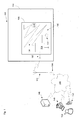
- a wired connection to network 140 is available close to the controller 104, then a wired connection instead of a wireless connection may be provided.
- a wireless access point rather than a mobile phone antenna, may provide the communication path to the network 140. Irrespective of the specific physical layer connection, the controller 104 can send messages to remote devices connected to network 140 in order to notify the status of the environment being monitored.
- FIG. 2 shows a longitudinal sectional view through a part of an embodiment of the linear sensor 106 configured to detect excess temperature which illustrates its physical construction and is designated generally 160.
- the linear sensor 160 includes a pair of twisted wires 162, 164, each including a tin plated, copper coated, steel core, 166, 168, and having a coating of insulating material 170, 172 formed on the wire cores.
- the tin plating helps to prevent oxidation and corrosion
- the copper coating provides increased conductivity
- the steel core provides resilience, or springiness, as the wires are held under tension by twisting.
- the insulating coatings 170, 172 are made of a non-electrically conductive material, which softens at a particular pre-selected temperature.
- a suitable material is a low density polyethylene (LDPE) and is available from Total Petrochemicals.
- the linear sensor cable 160 has an outer housing 174 of polyvinyl chloride (PVC) to provide environmental protection.
- PVC polyviny
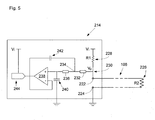
- controller 104 includes a micro-processor 216.
- micro-processor 216 Various types of microprocessor can be used. However, an 8-bit microprocessor can be preferred to help reduce cost.
- microprocessor 216 includes at least one register 218, which will be an 8-bit register when microprocessor 216 is an 8-bit microprocessor.
- Resistors R1 and R2 are arranged to provide a voltage divider in which the output voltage Vo is given by Vi x R2/(R1 + R2).
- the values of R1 and R2 are selected such that Vo ⁇ Vi12 when the linear sensor does not have a fault and does not include any short circuit.
- the resistance of R2 can be approximately 80% of the resistance of R1.
- the controller can use only the two most significant bits of the analog to digital converter (ADC) output in order reliably to determine the state of the linear sensor, owing to the choice of the value of R2 relative to R1.
- the microprocessor does not need to read all 10-bits of the output but rather reads only the two most significant bits into one of its 8-bit registers.
- Vo ⁇ Vi in a fault state of the linear sensor, Vo ⁇ Vi and so the most significant bit of the ADC output will be set, i.e. 1.
- Vo ⁇ 0.44Vi In a normal state of the linear sensor, Vo ⁇ 0.44Vi, and so the most significant bit will not be set, but the 2 nd most significant bit will be set, i.e. 1.
- the state of the linear sensor can be represented by the following truth table: Value of Most Significant Bit Value of 2 nd Most Significant Bit State 1 1 Fault 1 0 Fault 0 1 Normal 0 0 Alarm
- Figure 6 shows a process flow chart illustrating a method 300 of operating the alarm system according to the invention. It will be appreciated that the overall process flow is controlled by microprocessor 216 with various operations carried out by the various components, modules and circuitry present in the controller 104.
- a process flow chart illustrating a method 300 of operating the controller of the alarm system.
- the method begins at step 302 with the controller powering on and carrying out various initialisations.
- the controller switches to a dormant or passive low power mode in which it does not monitor the status of the linear sensor.
- the controller After a delay, for example one minute, the controller enters a higher power active state in order to determine the status of the linear sensor.
- the microprocessor can check the current battery level of the controller. This need not be carried out every time, but may be carried out on a periodic basis, for example every day.
- the microprocessor interrogates the battery level monitor circuit and determines the current battery level for the onboard battery of the controller. Data items representing the current battery level are stored locally on the controller as a result of this query.
- step 328 the microprocessor determines whether the healthy flag has been set. If the healthy flag has been set, then processing proceeds to step 329 and the microprocessor determines whether a 'healthy' message has already been sent within a certain period, for example the last 24 hours or day. If it is determined at step 329 that a healthy message has already been sent 'today' then processing returns to step 304. Otherwise, if no 'healthy' message has already been sent today, then at step 330 and a "healthy" message is sent to a recipient device. This is done because checking the status of the linear sensor requires a small amount of power, whereas sending a message requires significantly more electrical power. Checking the status of the linear sensor should be done frequently, e.g.
- the longest period between discovering a fault/alarm status is less than or equal to one minute, but if everything is normal, then only one 'healthy' message is sent per day in order to preserve battery life.
- the healthy message includes data items indicating that the controller and linear sensor are operating normally and that no alarm condition has been detected.
- the healthy message may also include, optionally, data indicating of the current battery level of the controller and/or data items indicating the current geographical location of the controller, in order to help distinguish the controller from multiple different controllers which may be reporting to the same recipient device.
- the healthy message may also include a data item which is a unique identifier for the controller providing an alternative mechanism for identifying the source of the message.
- step 328 If it is determined at step 328 that the healthy flag is not set, then processing proceeds to step 332 at which it is determined whether the fault flag has been set. If the microprocessor determines the fault flag has been set at 332 and also that an acknowledgement flag has not been set, then a fault message is sent at step 334 to the recipient device.
- the microprocessor provides data items indicating that the linear sensor is in a fault state to the communicator module and may optionally also include data items indicating the current battery level and/or the current geographical location of the controller and/or a unique identifier for the controller. Then at step 334, the communicator module sends a message to the recipient device over the communication network indicating that the linear sensor has a fault.
- step 342 the controller waits for a preset period, for example ten minutes, and then at step 344, the microprocessor determines whether any acknowledgment message has been received by the controller via the communicator module. If at step 344, it is determined that an acknowledgement message has been received, then an acknowledgement flag is set at step 348 and processing returns to step 304. Processing then proceeds as described above, but on this loop, at step 332 it is determined that the Ack flag has also been set indicating that the fault message has been acknowledged and hence processing returns directly to step 304 without sending a fault message.
- step 338 it is determined whether the alarm flag has been set and also whether an acknowledgment flag has been set for an alarm message . If the alarm flag has not been set, then some error may have occurred in the controller and some other error handling or exception processing can be switched to. Otherwise, if it determined that the alarm flag has been set at step 338 and the corresponding acknowledgement flag has not been set, then an alarm message is sent by the controller at step 340. More specifically, the microprocessor instructs the communicator module to send a message to the remote recipient device including data items indicating that the linear sensor is in an alarm state having detected an anomalous environmental condition.
- the alarm message may optionally also include an indication of the current battery level of the controller and / or the current geographical position of the controller and / or a unique identifier for the controller.
- Other information can also be included in the alarm message, such as a time stamp in case there are delays between the message being transmitted and received.
- the notification sent by the controller 104 can be intended for various different receiver devices.
- a notification is only sent if an alarm state has been detected and the message can be sent as an SMS message to a wireless telecommunication device, such as a smart phone 152, associated with a user 150 responsible for the site being monitored by the alarm system.
- the end user 150 may be an owner, resident or caretaker of the building and the message may be a notification indicating that a fire or a flood has been detected. If the user has only a single property, then the location of the controller may not need to be sent as the user will be aware of the location of their property.
- the controller position information included in the notification can be processed so as to display a visual indication on a map of the building, or a plurality of different buildings, including controllers showing the location of the controller to which the linear sensor is attached.
- logic may be provided to further process the position of the controller in order to determine some ancillary information which might be useful in responding to the break. For example, logic may determine a nearest road or access point by which emergency services and/or maintenance personnel might access the site at which the alarm or fault has occurred.
- the controller being self contained in some embodiments, can still be used.
- the GPS module providing positional information, it is possible to easily determine the location of the alarm condition within a practicable distance, rather than having to search the entirety of a large site in order to try and identify the location of the cause of the alarm state.
- the provision of communication functionalities allows a notification, virtually in real time, of the occurrence of any alarm condition thereby improving the speed with which action can be taken.
- controller is not necessarily limited to the structures used to describe its functional properties.
- the functions provided by the controller may be realised in other circuitry, modules, parts and components as will be apparent to a person of ordinary skill in the art from the above teaching.
Landscapes
- Physics & Mathematics (AREA)
- General Physics & Mathematics (AREA)
- Business, Economics & Management (AREA)
- Emergency Management (AREA)
- Engineering & Computer Science (AREA)
- Computer Networks & Wireless Communication (AREA)
- Alarm Systems (AREA)
- Arrangements For Transmission Of Measured Signals (AREA)
Applications Claiming Priority (1)
| Application Number | Priority Date | Filing Date | Title |
|---|---|---|---|
| GB1208231.9A GB2501915A (en) | 2012-05-10 | 2012-05-10 | Environmental alarm system providing a remote alert |
Publications (2)
| Publication Number | Publication Date |
|---|---|
| EP2662845A2 true EP2662845A2 (de) | 2013-11-13 |
| EP2662845A3 EP2662845A3 (de) | 2016-04-27 |
Family
ID=46396839
Family Applications (1)
| Application Number | Title | Priority Date | Filing Date |
|---|---|---|---|
| EP13167378.2A Withdrawn EP2662845A3 (de) | 2012-05-10 | 2013-05-10 | Alarmsystem |
Country Status (2)
| Country | Link |
|---|---|
| EP (1) | EP2662845A3 (de) |
| GB (1) | GB2501915A (de) |
Cited By (8)
| Publication number | Priority date | Publication date | Assignee | Title |
|---|---|---|---|---|
| CN103941693A (zh) * | 2014-04-21 | 2014-07-23 | 江南大学 | 工厂环境质量智能监控系统 |
| CN104376677A (zh) * | 2014-12-09 | 2015-02-25 | 江苏中实电子有限公司 | 一种高灵敏复合线型感温火灾探测器及其报警方法 |
| WO2020239739A1 (fr) * | 2019-05-27 | 2020-12-03 | Saint-Gobain Placo | Systeme de detection de sinistres dans les batiments |
| EP3638999A4 (de) * | 2017-06-15 | 2021-01-20 | Mikrodust AB | System und verfahren zur detektion von feuchtigkeit mit einem kabel, kabel zur detektion von feuchtigkeit und feuchtigkeitsdetektionsvorrichtung |
| US11144079B2 (en) | 2013-02-11 | 2021-10-12 | Graco Minnesota Inc. | Remote monitoring for fluid applicator system |
| EP4240924A4 (de) * | 2020-11-06 | 2023-12-06 | Watts Regulator Co. | Intelligente dachablaufsysteme und verfahren |
| US11934211B2 (en) | 2013-02-11 | 2024-03-19 | Graco Minnesota Inc. | Paint sprayer distributed control and output volume monitoring architectures |
| US12012759B2 (en) | 2020-11-06 | 2024-06-18 | Watts Regulator Co. | Intelligent roof drain systems and methods |
Families Citing this family (1)
| Publication number | Priority date | Publication date | Assignee | Title |
|---|---|---|---|---|
| CN107365573B (zh) * | 2017-06-13 | 2020-03-31 | 中国石油天然气集团公司 | 一种中低温环保交联剂的制备方法及应用 |
Family Cites Families (10)
| Publication number | Priority date | Publication date | Assignee | Title |
|---|---|---|---|---|
| US4506253A (en) * | 1983-01-03 | 1985-03-19 | General Signal Corporation | Supervisory and control circuit for alarm system |
| US4926129A (en) * | 1988-10-12 | 1990-05-15 | Raychem Corporation | Sensor assembly for detecting multiple events and distinguishing between them |
| GB9408876D0 (en) * | 1994-05-04 | 1994-06-22 | Bilak Roman | Snow pack stability monitor |
| GB2291243B (en) * | 1994-07-05 | 1998-04-22 | Joan Ellen Shippen | Rain alarm |
| US6731215B2 (en) * | 2000-11-30 | 2004-05-04 | Frederick H. Harms | Moisture monitoring system |
| JP2004069680A (ja) * | 2002-06-10 | 2004-03-04 | Hiroshi Kurita | 構造物の異常検知システム |
| US20060192678A1 (en) * | 2005-02-25 | 2006-08-31 | Michael Garabedian | Ice dam warning system |
| US20060244616A1 (en) * | 2005-04-01 | 2006-11-02 | Clyde Hill | Moisture sensing strips |
| US7142123B1 (en) * | 2005-09-23 | 2006-11-28 | Lawrence Kates | Method and apparatus for detecting moisture in building materials |
| GB2453970A (en) * | 2007-10-23 | 2009-04-29 | Andrew Beswick | Detecting hazardous chemicals in an environment using a conductive polymer chemical fuse |
-
2012
- 2012-05-10 GB GB1208231.9A patent/GB2501915A/en not_active Withdrawn
-
2013
- 2013-05-10 EP EP13167378.2A patent/EP2662845A3/de not_active Withdrawn
Cited By (19)
| Publication number | Priority date | Publication date | Assignee | Title |
|---|---|---|---|---|
| US11934211B2 (en) | 2013-02-11 | 2024-03-19 | Graco Minnesota Inc. | Paint sprayer distributed control and output volume monitoring architectures |
| US11698650B2 (en) | 2013-02-11 | 2023-07-11 | Graco Minnesota Inc. | Remote monitoring for fluid applicator system |
| US12339678B2 (en) | 2013-02-11 | 2025-06-24 | Graco Minnesota Inc. | Paint sprayer distributed control and output volume monitoring architectures |
| US11630470B2 (en) | 2013-02-11 | 2023-04-18 | Graco Inc. | Remote monitoring for fluid applicator system |
| US12135568B2 (en) | 2013-02-11 | 2024-11-05 | Graco Minnesota Inc. | Remote monitoring for fluid applicator system |
| US11144079B2 (en) | 2013-02-11 | 2021-10-12 | Graco Minnesota Inc. | Remote monitoring for fluid applicator system |
| US11249498B2 (en) | 2013-02-11 | 2022-02-15 | Graco Minnesota Inc. | Remote monitoring for fluid applicator system |
| US11372432B2 (en) | 2013-02-11 | 2022-06-28 | Graco Minnesota Inc. | Remote monitoring for fluid applicator system |
| US11934212B2 (en) | 2013-02-11 | 2024-03-19 | Graco Minnesota Inc. | Paint sprayer distributed control and output volume monitoring architectures |
| US11592850B2 (en) | 2013-02-11 | 2023-02-28 | Graco Minnesota Inc. | Remote monitoring for fluid applicator system |
| US11934210B2 (en) | 2013-02-11 | 2024-03-19 | Graco Minnesota Inc. | Paint sprayer distributed control and output volume monitoring architectures |
| CN103941693A (zh) * | 2014-04-21 | 2014-07-23 | 江南大学 | 工厂环境质量智能监控系统 |
| CN104376677A (zh) * | 2014-12-09 | 2015-02-25 | 江苏中实电子有限公司 | 一种高灵敏复合线型感温火灾探测器及其报警方法 |
| EP3638999A4 (de) * | 2017-06-15 | 2021-01-20 | Mikrodust AB | System und verfahren zur detektion von feuchtigkeit mit einem kabel, kabel zur detektion von feuchtigkeit und feuchtigkeitsdetektionsvorrichtung |
| FR3096779A1 (fr) * | 2019-05-27 | 2020-12-04 | Saint-Gobain Placo | Systeme de detection de sinistres dans les batiments |
| WO2020239739A1 (fr) * | 2019-05-27 | 2020-12-03 | Saint-Gobain Placo | Systeme de detection de sinistres dans les batiments |
| EP4240924A4 (de) * | 2020-11-06 | 2023-12-06 | Watts Regulator Co. | Intelligente dachablaufsysteme und verfahren |
| US12012760B2 (en) | 2020-11-06 | 2024-06-18 | Watts Regulator Co. | Intelligent roof drain systems and methods |
| US12012759B2 (en) | 2020-11-06 | 2024-06-18 | Watts Regulator Co. | Intelligent roof drain systems and methods |
Also Published As
| Publication number | Publication date |
|---|---|
| GB201208231D0 (en) | 2012-06-20 |
| GB2501915A (en) | 2013-11-13 |
| EP2662845A3 (de) | 2016-04-27 |
Similar Documents
| Publication | Publication Date | Title |
|---|---|---|
| EP2662845A2 (de) | Alarmsystem | |
| US7053765B1 (en) | Active security system | |
| CN102024312B (zh) | 通过公用事业仪表读数基础设施进行报警报告 | |
| US6703930B2 (en) | Personal alerting apparatus and methods | |
| JP6509598B2 (ja) | 見守り支援システム | |
| KR101296150B1 (ko) | 호별 id 정보를 활용한 초고층 건축물 화재감지, 경보 시스템 및 방법 | |
| US20090289787A1 (en) | Residential security cluster with associated alarm interconnects | |
| AU2012214105B2 (en) | Wirelessly networked fluid monitoring method, system and apparatus | |
| JP5815278B2 (ja) | 警報連携システム | |
| Mahgoub et al. | Fire alarm system for smart cities using edge computing | |
| JP6022797B2 (ja) | 警報連携システム | |
| US20080243391A1 (en) | Information Managing/Providing System and Method | |
| US20150123782A1 (en) | Supervising alarm notification devices | |
| JP5249161B2 (ja) | 警報器および警報システム | |
| Al-Ali et al. | GRPS-based distributed home-monitoring using internet-based geographical information system | |
| US10663368B2 (en) | Modular leak detector and method of use | |
| JP4643060B2 (ja) | 電力量計、データ送信装置、データ送信制御プログラム、電力量管理システム、データ送信制御方法 | |
| EP1815452B1 (de) | System von einrichtungen mit mehreren mit einem zentralen gateway-gerät kommunizierenden sensorgeräten | |
| JP2010272101A (ja) | 警報器 | |
| JP2011081595A (ja) | 警報システム、警報器及び緊急呼出装置 | |
| US10699551B1 (en) | Outdoor Wi-Fi enabled fluid level alarm | |
| JP2022024850A (ja) | 情報報知方法、プログラム、分電盤及び情報報知システム | |
| JP5324300B2 (ja) | 警報器及び警報システム | |
| JP2005184190A (ja) | 監視装置およびそのプログラム | |
| JP5443635B2 (ja) | 警報システム |
Legal Events
| Date | Code | Title | Description |
|---|---|---|---|
| PUAI | Public reference made under article 153(3) epc to a published international application that has entered the european phase |
Free format text: ORIGINAL CODE: 0009012 |
|
| AK | Designated contracting states |
Kind code of ref document: A2 Designated state(s): AL AT BE BG CH CY CZ DE DK EE ES FI FR GB GR HR HU IE IS IT LI LT LU LV MC MK MT NL NO PL PT RO RS SE SI SK SM TR |
|
| AX | Request for extension of the european patent |
Extension state: BA ME |
|
| PUAL | Search report despatched |
Free format text: ORIGINAL CODE: 0009013 |
|
| AK | Designated contracting states |
Kind code of ref document: A3 Designated state(s): AL AT BE BG CH CY CZ DE DK EE ES FI FR GB GR HR HU IE IS IT LI LT LU LV MC MK MT NL NO PL PT RO RS SE SI SK SM TR |
|
| AX | Request for extension of the european patent |
Extension state: BA ME |
|
| RIC1 | Information provided on ipc code assigned before grant |
Ipc: G08B 17/06 20060101AFI20160329BHEP Ipc: G08B 25/10 20060101ALI20160329BHEP Ipc: G01M 3/16 20060101ALI20160329BHEP Ipc: G08B 25/04 20060101ALI20160329BHEP Ipc: G08B 21/20 20060101ALI20160329BHEP Ipc: G01M 3/04 20060101ALI20160329BHEP |
|
| STAA | Information on the status of an ep patent application or granted ep patent |
Free format text: STATUS: THE APPLICATION HAS BEEN PUBLISHED |
|
| STAA | Information on the status of an ep patent application or granted ep patent |
Free format text: STATUS: THE APPLICATION IS DEEMED TO BE WITHDRAWN |
|
| 18D | Application deemed to be withdrawn |
Effective date: 20161028 |