EP2662575A2 - Membrane and container assembly - Google Patents
Membrane and container assembly Download PDFInfo
- Publication number
- EP2662575A2 EP2662575A2 EP13165977.3A EP13165977A EP2662575A2 EP 2662575 A2 EP2662575 A2 EP 2662575A2 EP 13165977 A EP13165977 A EP 13165977A EP 2662575 A2 EP2662575 A2 EP 2662575A2
- Authority
- EP
- European Patent Office
- Prior art keywords
- container
- membrane
- connecting element
- halves
- container halves
- Prior art date
- Legal status (The legal status is an assumption and is not a legal conclusion. Google has not performed a legal analysis and makes no representation as to the accuracy of the status listed.)
- Withdrawn
Links
- 239000012528 membrane Substances 0.000 title claims abstract description 89
- 238000005304 joining Methods 0.000 claims abstract description 16
- 239000013013 elastic material Substances 0.000 claims abstract description 7
- 239000012790 adhesive layer Substances 0.000 claims abstract description 4
- 239000000463 material Substances 0.000 claims description 13
- 239000010410 layer Substances 0.000 claims description 8
- 239000002184 metal Substances 0.000 claims description 2
- 239000007788 liquid Substances 0.000 description 11
- 239000007789 gas Substances 0.000 description 9
- 238000003466 welding Methods 0.000 description 6
- 229920001971 elastomer Polymers 0.000 description 4
- XLYOFNOQVPJJNP-UHFFFAOYSA-N water Substances O XLYOFNOQVPJJNP-UHFFFAOYSA-N 0.000 description 4
- 238000009434 installation Methods 0.000 description 3
- IJGRMHOSHXDMSA-UHFFFAOYSA-N nitrogen Substances N#N IJGRMHOSHXDMSA-UHFFFAOYSA-N 0.000 description 3
- 230000002093 peripheral effect Effects 0.000 description 3
- 239000005060 rubber Substances 0.000 description 3
- 229920002943 EPDM rubber Polymers 0.000 description 2
- 244000043261 Hevea brasiliensis Species 0.000 description 2
- 229920000459 Nitrile rubber Polymers 0.000 description 2
- 229910000831 Steel Inorganic materials 0.000 description 2
- 239000000853 adhesive Substances 0.000 description 2
- 230000001070 adhesive effect Effects 0.000 description 2
- 239000011324 bead Substances 0.000 description 2
- 229920005549 butyl rubber Polymers 0.000 description 2
- 239000012530 fluid Substances 0.000 description 2
- 238000010438 heat treatment Methods 0.000 description 2
- 238000004519 manufacturing process Methods 0.000 description 2
- 229920003052 natural elastomer Polymers 0.000 description 2
- 229920001194 natural rubber Polymers 0.000 description 2
- 229910052757 nitrogen Inorganic materials 0.000 description 2
- 239000010959 steel Substances 0.000 description 2
- 229920003048 styrene butadiene rubber Polymers 0.000 description 2
- 239000002174 Styrene-butadiene Substances 0.000 description 1
- 230000001186 cumulative effect Effects 0.000 description 1
- 230000001419 dependent effect Effects 0.000 description 1
- 239000000806 elastomer Substances 0.000 description 1
- 229920001973 fluoroelastomer Polymers 0.000 description 1
- 229920002681 hypalon Polymers 0.000 description 1
- 238000000034 method Methods 0.000 description 1
- 239000000203 mixture Substances 0.000 description 1
- QJGQUHMNIGDVPM-UHFFFAOYSA-N nitrogen group Chemical group [N] QJGQUHMNIGDVPM-UHFFFAOYSA-N 0.000 description 1
- 238000003860 storage Methods 0.000 description 1
- 229920002725 thermoplastic elastomer Polymers 0.000 description 1
Images


Classifications
-
- F—MECHANICAL ENGINEERING; LIGHTING; HEATING; WEAPONS; BLASTING
- F15—FLUID-PRESSURE ACTUATORS; HYDRAULICS OR PNEUMATICS IN GENERAL
- F15B—SYSTEMS ACTING BY MEANS OF FLUIDS IN GENERAL; FLUID-PRESSURE ACTUATORS, e.g. SERVOMOTORS; DETAILS OF FLUID-PRESSURE SYSTEMS, NOT OTHERWISE PROVIDED FOR
- F15B1/00—Installations or systems with accumulators; Supply reservoir or sump assemblies
- F15B1/02—Installations or systems with accumulators
- F15B1/04—Accumulators
- F15B1/08—Accumulators using a gas cushion; Gas charging devices; Indicators or floats therefor
- F15B1/10—Accumulators using a gas cushion; Gas charging devices; Indicators or floats therefor with flexible separating means
- F15B1/12—Accumulators using a gas cushion; Gas charging devices; Indicators or floats therefor with flexible separating means attached at their periphery
- F15B1/14—Accumulators using a gas cushion; Gas charging devices; Indicators or floats therefor with flexible separating means attached at their periphery by means of a rigid annular supporting member
-
- F—MECHANICAL ENGINEERING; LIGHTING; HEATING; WEAPONS; BLASTING
- F15—FLUID-PRESSURE ACTUATORS; HYDRAULICS OR PNEUMATICS IN GENERAL
- F15B—SYSTEMS ACTING BY MEANS OF FLUIDS IN GENERAL; FLUID-PRESSURE ACTUATORS, e.g. SERVOMOTORS; DETAILS OF FLUID-PRESSURE SYSTEMS, NOT OTHERWISE PROVIDED FOR
- F15B2201/00—Accumulators
- F15B2201/20—Accumulator cushioning means
- F15B2201/205—Accumulator cushioning means using gas
-
- F—MECHANICAL ENGINEERING; LIGHTING; HEATING; WEAPONS; BLASTING
- F15—FLUID-PRESSURE ACTUATORS; HYDRAULICS OR PNEUMATICS IN GENERAL
- F15B—SYSTEMS ACTING BY MEANS OF FLUIDS IN GENERAL; FLUID-PRESSURE ACTUATORS, e.g. SERVOMOTORS; DETAILS OF FLUID-PRESSURE SYSTEMS, NOT OTHERWISE PROVIDED FOR
- F15B2201/00—Accumulators
- F15B2201/30—Accumulator separating means
- F15B2201/315—Accumulator separating means having flexible separating means
- F15B2201/3151—Accumulator separating means having flexible separating means the flexible separating means being diaphragms or membranes
-
- F—MECHANICAL ENGINEERING; LIGHTING; HEATING; WEAPONS; BLASTING
- F15—FLUID-PRESSURE ACTUATORS; HYDRAULICS OR PNEUMATICS IN GENERAL
- F15B—SYSTEMS ACTING BY MEANS OF FLUIDS IN GENERAL; FLUID-PRESSURE ACTUATORS, e.g. SERVOMOTORS; DETAILS OF FLUID-PRESSURE SYSTEMS, NOT OTHERWISE PROVIDED FOR
- F15B2201/00—Accumulators
- F15B2201/30—Accumulator separating means
- F15B2201/315—Accumulator separating means having flexible separating means
- F15B2201/3156—Accumulator separating means having flexible separating means characterised by their attachment
-
- F—MECHANICAL ENGINEERING; LIGHTING; HEATING; WEAPONS; BLASTING
- F15—FLUID-PRESSURE ACTUATORS; HYDRAULICS OR PNEUMATICS IN GENERAL
- F15B—SYSTEMS ACTING BY MEANS OF FLUIDS IN GENERAL; FLUID-PRESSURE ACTUATORS, e.g. SERVOMOTORS; DETAILS OF FLUID-PRESSURE SYSTEMS, NOT OTHERWISE PROVIDED FOR
- F15B2201/00—Accumulators
- F15B2201/40—Constructional details of accumulators not otherwise provided for
- F15B2201/405—Housings
- F15B2201/4056—Housings characterised by the attachment of housing components
-
- F—MECHANICAL ENGINEERING; LIGHTING; HEATING; WEAPONS; BLASTING
- F15—FLUID-PRESSURE ACTUATORS; HYDRAULICS OR PNEUMATICS IN GENERAL
- F15B—SYSTEMS ACTING BY MEANS OF FLUIDS IN GENERAL; FLUID-PRESSURE ACTUATORS, e.g. SERVOMOTORS; DETAILS OF FLUID-PRESSURE SYSTEMS, NOT OTHERWISE PROVIDED FOR
- F15B2201/00—Accumulators
- F15B2201/60—Assembling or methods for making accumulators
- F15B2201/605—Assembling or methods for making housings therefor
-
- F—MECHANICAL ENGINEERING; LIGHTING; HEATING; WEAPONS; BLASTING
- F15—FLUID-PRESSURE ACTUATORS; HYDRAULICS OR PNEUMATICS IN GENERAL
- F15B—SYSTEMS ACTING BY MEANS OF FLUIDS IN GENERAL; FLUID-PRESSURE ACTUATORS, e.g. SERVOMOTORS; DETAILS OF FLUID-PRESSURE SYSTEMS, NOT OTHERWISE PROVIDED FOR
- F15B2201/00—Accumulators
- F15B2201/60—Assembling or methods for making accumulators
- F15B2201/61—Assembling or methods for making separating means therefor
Definitions
- the present invention relates to a membrane of a container, in particular a pressure expansion vessel, as well as a container arrangement, which is designed in particular as a pressure expansion vessel.
- Expansion tanks or surge tank of the type in question are well known in the art.
- surge tanks are designed as components in hydraulic systems that absorb the change in volume of the hydraulic fluid between minimum and maximum temperature and thus should keep the pressure largely constant.
- expansion tanks are used in heating systems and service water, cold water, solar and hydraulic circuits.
- Such reservoirs have a flexible rubber membrane, which separates the liquid and the gas storage within a vessel formed by two half-shells. Here, the membrane is clamped between the two half-shells on the outer bead and held together with a rotating steel clip.
- a disadvantage of such embodiments is that the container wall must be made massive due to the forces occurring and the structural connection of the two half-shells. Incidentally, the installation space must be kept relatively large because of the peripheral edge. Incidentally, the complex installation of such systems leads to high production costs.
- a membrane of a container in particular a pressure expansion vessel or expansion tank, wherein the membrane is formed of an elastic material, and wherein the membrane has a working area which is adapted to displace within a container, and a mounting area has, over which the membrane in the region of two joining regions of two container halves on the container can be fixed, that the container halves are connected to one another via a material connection.
- the membrane thus serves in particular for use in a membrane expansion vessel and is thus designed as a preferably flexible rubber membrane.
- the membrane advantageously consists of an elastic material or elastomer so as to shift at least in its working area within the container.
- the materials used for the membrane are NBR (nitrile-butadiene rubber), EPDM (ethylene-propylene-diene rubber), SBR (styrene-butadiene rubber), CSM (chlorosulfonated polyethylene), FKM (fluoro rubber), NR (natural rubber) , TPV (thermoplastic elastomer) or IIR (butyl rubber) in question.
- the membrane may be formed from mixtures of the aforementioned materials.
- the membrane may have a layered structure of different materials. The membrane serves to separate the liquid from a gas cushion. When heated, the nearly incompressible liquid expands, compressing the gas cushion on the other side of the membrane.
- the membrane is designed as a flat body and particularly expediently, this has a (fairly) square or round, preferably circular, planar configuration.
- the edge regions of the membrane the latter has a fastening region, by way of which the membrane can be fixed to the container in the region of two joining regions of two container halves, so that the container halves can be connected to one another via a material connection.
- the attachment region of the membrane can thus be a peripheral edge.
- the joining region of a container half generally represents the region or section of the container half, via which the container half is connected or connectable to another container half or another element.
- the fastening area is designed such that it is not clamped between the two container halves and clamped by a clamping ring, but in such a way that a cohesive connection of the two container halves is possible with each other.
- the cohesive connection of the two container halves can be effected here indirectly or directly. In an immediate cohesive connection of the container halves they are directly contacting each other, for example glued or welded. In an indirect connection of the two container halves, an intermediate element, for example a connecting element, is provided, on which the two container halves are fixed cohesively.
- the attachment region has an adhesion layer in order to fix it to at least one of the container halves or a connecting element.
- the adhesion layer may for example be formed as an adhesive layer or adhesive layer and connects the attachment region of the membrane with at least one of the container halves or a connecting element such that a gas flow or a fluid flow can not occur.
- the advantageously forming the outer periphery of the diaphragm mounting portion may therefore be determined directly or indirectly on at least one of the container halves.
- the membrane is conveniently glued to the inner peripheral surface of the container half.
- the fastening region of the membrane to a connecting element is expediently determined by way of bonding or welding. in this respect It is particularly useful when the mounting area is set adjacent to the joining area at the two container halves.
- the attachment region is non-positively and / or positively and / or materially connected to a connecting element, via which the membrane can be fixed to at least one of the container halves.
- the connection between the membrane and the connecting element can for example be made cohesively.
- the attachment region of the membrane can be glued or welded to the connecting element.
- a non-positive and / or positive connection can also be created.
- the connecting element can be vulcanized into the fastening region of the membrane.
- the engagement areas may be formed, for example, as recesses, projections or openings or the like.
- the connecting element is made of an adhesive or weldable material, preferably a metal such as steel.
- the connecting element and at least one of the container halves are made of the same material. This makes it possible to materially connect one or both container halves to the connecting element, for example via a weld.
- the membrane is connected either to the connecting element or to at least one of the container halves. So it is not necessary for the attachment of the membrane several components.
- the membrane can be explicitly attached to the connector without touching the container half (s) at the same time.
- the membrane may be secured to one of the container halves without the other container half and / or the connecting element to touch or on both container halves, without touching the connecting element.
- a plane is formed substantially centrally between the container halves, wherein the fastening region is arranged in this plane.
- the plane can also be referred to as a parting plane, since it separates the two container halves, so to speak. To form the plane, the container halves do not have to touch each other. The plane, even if the container halves are spaced apart, extends substantially midway between the container halves. Expediently, the plane is arranged substantially centrally or even offset between two joining regions of two container halves and substantially parallel (or not) between two joining regions of two container halves. If the container halves are welded on impact, the two joining regions of the container halves expediently form the plane together. More generally, the container halves form a free space between them.
- the mounting area is positioned in the region of the free space.
- a container arrangement in particular a pressure expansion vessel or membrane expansion vessel, comprising two container halves and a membrane made of an elastic material, wherein the membrane has a working area, which is designed to be displaced within the container, and wherein the membrane has a mounting area has, over which the membrane in such a range of two joining areas of the container halves is fixed to this, that the container halves are connected or connected to each other via a material connection.
- a container arrangement is thus provided in which the two container halves are not clamped together by a clamping ring, but which are connected to one another via a cohesive connection or connectable.
- the cohesive connection can in this case directly or directly, for example, by welding together the two container halves, or indirectly, for example, by welding the two container halves to a vitelagertes Element or connecting element, take place. It is understood that the further advantages and features as described with regard to the membrane according to the invention can also be used in the container arrangement according to the invention.
- the fastening region is non-positively and / or positively and / or materially connected to at least one of the container halves or a connecting element.
- the membrane can also be connected via its mounting region with two container halves.
- the fastening region in the assembled state of the container halves on the one or between the two flanges can be fixed cohesively and / or non-positively and positively. Seen radially outwards, the two container halves can then butt against one another and be glued or welded together or be connected to one another in another cohesive connection method.
- the fastening region preferably has an adhesion layer, via which it is fixed to at least one of the container halves or the connecting element. This makes it possible to fix the attachment region of the membrane cohesively to the connecting element or at least one of the container halves.
- At least one of the container halves or the connecting element has engagement regions, via which the fastening region is non-positively and positively connected to at least one of the container halves or the connecting element.
- the engagement regions may be formed, for example, as projections, recesses, recesses or openings. In this case, it is possible for the container halves or the connecting element to be vulcanized or cast into the region of attachment of the membrane in the region of the engagement regions.
- a connecting element is provided, via which the fastening region is fixed to at least one of the container halves.
- the membrane is thus not directly or directly fixed to the container or the container halves. Rather, the definition of the membrane is indirectly or indirectly via the intermediate connection element.
- the connecting element is designed as an annular body, which is fixed to the joining areas of the container halves such that the connecting element forms a part of the container wall.
- the connecting element forms part of the container outer wall and is designed for this purpose as a ring-shaped or cylindrical body.
- the connecting element is arranged on the respective inner lateral surface or outer lateral surface of the respective container half, that is, the cylinder jacket surface of the connecting element expediently contacts the cylindrical outer surface of each container half.
- the container halves are fixed to the opposite end faces of the cylindrical or annular body. In other words, in the former alternative, the connecting element and the respective container halves overlap in the longitudinal direction, whereas in the second alternative, the container halves and the connecting element do not overlap, but are connected to one another adjacent to one another.
- the connecting element is non-positively and / or positively and / or materially fixed to the joining areas of the container halves.
- the connecting element is firmly bonded to the joining areas of the respective container halves via an adhesive connection or welded connection.
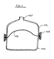
- FIG. 1 is a known from the prior art embodiment of a membrane expansion vessel shown.
- This has an upper container half 102, a lower container half 104 and a membrane 106.
- the membrane 106 divides the container formed by the upper container half 102 and lower container half 104 into two spaces.
- the membrane is clamped by a bead located at its edge by means of a clamping ring 108 between the two container halves 102, 104.
- a liquid for example water, which can enter and leave via a connection 110.
- FIG. 2 are a sectional view and a detailed sectional view of a preferred exemplary embodiment of the container assembly according to the invention shown.
- the container arrangement has a first or upper container half 2, a second or lower container half 4 and a membrane 6.
- the two container halves 2, 4 are expediently designed as closed on one side, cylindrical container.
- the diaphragm 6 divides the space formed by the container halves 2, 4 into two partial areas, namely a lower partial area, in which advantageously a gas, such as nitrogen, is provided and an upper portion, in which a liquid, such as water is present.
- the gas cushion arranged on the other membrane side is compressed upon heating due to the incompressibility of the liquid, so that due to the flexible membrane a pressure compensation between liquid and gas cushion is made possible.
- the upper container half 2 has a connection 8 in order to supply and remove the liquid to the container arrangement.
- a connecting element 10 is provided, by means of which the membrane 6 is fixed indirectly to the two container halves 2, 4.
- the membrane 6 is expediently flexible, in particular of an elastic material, for example rubber.
- the membrane 6 has a working area 12 which can shift within the container arrangement.
- the working area 12 is in particular a central region of the membrane 6.
- a fastening area 14 is provided beyond which the membrane 6 can be fixed directly or indirectly to at least one of the container halves 2, 4.
- the connecting element 10 is formed as a cylindrical body, on whose - viewed in the radial direction r - inner lateral surface in the longitudinal direction l at least partially overlapping the first container half 2 and second container half 4 is arranged.
- the first container half 2 is directly connected via a cohesive connection in the form of a weld 16 to the connecting element 10.
- the two end edges of the container halves 2, 4 do not abut each other, but are spaced apart such that a free space 18 is formed between them.
- This is an adhesion layer 20 is provided, which creates a material connection between the membrane 6 and connecting element 10.
- FIG. 3 is a further preferred, exemplary embodiment of the container assembly according to the invention shown.
- the connecting element 10 is not arranged in the longitudinal direction l overlapping with the two container halves 2, 4, but is located between the two end sides of the container halves 2, 4. In other words, contact the end faces of the container halves 2, 4, the end face of the annular connecting element 10th and are connected to each other via a weld 22 at their respective end faces cohesively.
- the connecting element 10 has engaging regions 24 in its radially inwardly directed region in order to connect the fastening region 14 of the diaphragm 6 positively and positively to the connecting element 10. Additionally or alternatively, the membrane 6 can also be connected to the connecting element 10 via an adhesion layer.
- FIG. 4 is a further preferred, exemplary embodiment of the container assembly according to the invention shown.
- the two container halves 2, 4 have at their end faces in each case one in the radial direction r inwardly projecting flange 26, which serves to fix the diaphragm 6.
- the attachment region 14 of the membrane 6 on the flange 26 facing sides may have an adhesion layer 20.
- the attachment portion 14 on the two flanges 26 facing sides each have an adhesion layer 20.
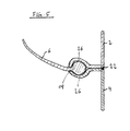
- a combination of fixing the fastening region 14 to the flange 26 via a non-positive and positive connection would be conceivable, as shown in FIG FIG. 5 is shown.
- the two flanges 26 are concavely formed at their mutually facing sides to receive a receiving space for a bead-like region or edge region of the membrane 6 therein.
- the end faces of the two container halves 2, 4 contact each other directly and are adhesively connected to one another via a bond 28.
- the cohesive connection can also be brought about by welding.
Landscapes
- Engineering & Computer Science (AREA)
- Physics & Mathematics (AREA)
- Fluid Mechanics (AREA)
- Mechanical Engineering (AREA)
- General Engineering & Computer Science (AREA)
- Filling Or Discharging Of Gas Storage Vessels (AREA)
- Separation Using Semi-Permeable Membranes (AREA)
Abstract
Description
Die vorliegende Erfindung betrifft eine Membrane eines Behälters, insbesondere eines Druckausdehnungsgefäßes, sowie eine Behälteranordnung, welche insbesondere als Druckausdehnungsgefäß ausgebildet ist.The present invention relates to a membrane of a container, in particular a pressure expansion vessel, as well as a container arrangement, which is designed in particular as a pressure expansion vessel.
Ausdehnungsgefäße bzw. Druckausgleichsbehälter der in Rede stehenden Art sind hinlänglich aus dem Stand der Technik bekannt. So werden derartige Druckausgleichsbehälter als Bauteile in hydraulischen Systemen ausgebildet, die die Volumenänderung der Hydraulikflüssigkeit zwischen minimaler und maximaler Temperatur aufnehmen und so den Druck weitgehend konstant halten sollen. Häufig werden derartige Ausdehnungsgefäße in Heizungsanlagen sowie Brauchwasser, Kaltwasser, Solar- und Hydraulikkreisläufen eingesetzt. Derartige Ausgleichsbehälter weisen eine flexible Gummimembrane auf, die die Flüssigkeit und den Gasspeicher innerhalb eines durch zwei Halbschalen ausgebildeten Gefäßes trennt. Hierbei wird die Membrane zwischen den zwei Halbschalen über den außen liegenden Wulst geklemmt und mit einer umlaufenden Stahlklammer zusammen gehalten. Nachteilig bei derartigen Ausführungsformen ist jedoch, dass die Behälterwand aufgrund der auftretenden Kräfte und der konstruktiven Verbindung der zwei Halbschalen massiv ausgeführt werden muss. Im Übrigen muss der Einbauraum wegen des umlaufenden Rands verhältnismäßig groß gehalten werden. Im Übrigen führt die aufwendige Montage derartiger Systeme zu hohen Herstellungskosten.Expansion tanks or surge tank of the type in question are well known in the art. Thus, such surge tanks are designed as components in hydraulic systems that absorb the change in volume of the hydraulic fluid between minimum and maximum temperature and thus should keep the pressure largely constant. Frequently, such expansion tanks are used in heating systems and service water, cold water, solar and hydraulic circuits. Such reservoirs have a flexible rubber membrane, which separates the liquid and the gas storage within a vessel formed by two half-shells. Here, the membrane is clamped between the two half-shells on the outer bead and held together with a rotating steel clip. A disadvantage of such embodiments, however, is that the container wall must be made massive due to the forces occurring and the structural connection of the two half-shells. Incidentally, the installation space must be kept relatively large because of the peripheral edge. Incidentally, the complex installation of such systems leads to high production costs.
Es ist somit Aufgabe der vorliegenden Erfindung, eine Membrane eines Behälters sowie eine Behälteranordnung, insbesondere ein Druckausdehnungsgefäß, vorzusehen, welche eine hohe Stabilität bei gleichzeitig geringen Herstellungskosten und geringem Einbauraum ermöglichen.It is therefore an object of the present invention to provide a membrane of a container and a container arrangement, in particular a pressure expansion vessel, which allow a high stability at the same time low production costs and low installation space.
Diese Aufgabe wird durch eine Membrane eines Behälters, insbesondere eines Druckausdehnungsgefäßes, mit den Merkmalen des Anspruchs 1 und durch eine Behälteranordnung, insbesondere Druckausdehnungsgefäß, mit den Merkmalen des Anspruchs 5 gelöst. Bevorzugte Ausführungsformen sind Gegenstand der abhängigen Ansprüche.This object is achieved by a membrane of a container, in particular a pressure expansion vessel, with the features of claim 1 and by a container arrangement, in particular pressure expansion vessel, having the features of claim 5. Preferred embodiments are subject of the dependent claims.
Erfindungsgemäß ist eine Membrane eines Behälters, insbesondere eines Druckausdehnungsgefäßes bzw. Druckausgleichsbehälter bzw. Membranausdehnungsgefäßes, vorgesehen, wobei die Membrane aus einem elastischen Material ausgebildet ist, und wobei die Membrane einen Arbeitsbereich, welcher ausgelegt ist, sich innerhalb eines Behälters zu verlagern, und einen Befestigungsbereich aufweist, über welchen die Membrane derart im Bereich von zwei Fügebereichen zweier Behälterhälften an dem Behälter festlegbar ist, dass die Behälterhälften über eine stoffschlüssige Verbindung miteinander verbindbar sind. Die Membrane dient somit insbesondere der Anwendung in einem Membranausdehnungsgefäß und ist somit als vorzugsweise flexible Gummimembrane ausgebildet. Hiefür besteht die Membrane vorteilhafterweise aus einem elastischen Material bzw. Elastomer, um somit zumindest in ihrem Arbeitsbereich sich innerhalb des Behälters zu verlagern. Als Materialien für die Membrane kommen NBR (Nitril-Butadien-Kautschuk), EPDM (Ethylen-Propylen-Dien-Kautschuk), SBR (Styrol-Butadien-Kautschuk), CSM (Chlorsulfoniertes Polyethylen), FKM (Fluorkautschuk), NR (Naturkautschuk), TPV (thermoplastisches Elastomer) oder IIR (Butylkautschuk) in Frage. Ferner kann die Membrane aus Mischungen der zuvor genannten Materialien ausgebildet sein. Auch kann die Membrane einen schichtweisen Aufbau aus verschiedenen Materialien besitzen. Die Membrane dient dazu, die Flüssigkeit von einem Gaspolster zu trennen. Bei Erwärmung dehnt sich die nahezu inkompressible Flüssigkeit aus und verdichtet somit das Gaspolster auf der anderen Membranseite. Aufgrund der flexiblen Ausgestaltung zumindest des Arbeitsbereichs kann sich dieser somit innerhalb des Behälters derart verlagern, dass ein Druckausgleich zwischen Flüssigkeit und Gaspolster ermöglicht werden kann. Vorteilhafterweise ist die Membrane als flächiger Körper ausgebildet und besonders zweckmäßigerweise weist diese eine (recht)eckige oder runde, vorzugsweise kreisrunde, flächige Konfiguration auf. Vorteilhafterweise in den Randbereichen der Membrane weist diese einen Befestigungsbereich auf, über welchen die Membrane derart im Bereich von zwei Fügebereichen zweier Behälterhälften an dem Behälter festlegbar ist, dass die Behälterhälften über eine stoffschlüssige Verbindung miteinander verbindbar sind. Der Befestigungsbereich der Membrane kann somit ein umlaufender Rand sein. Der Fügebereich einer Behälterhälfte stellt dabei allgemein den Bereich oder Abschnitt der Behälterhälfte dar, über welchen die Behälterhälfte mit einer anderen Behälterhälfte oder einem anderen Element verbunden oder verbindbar ist. Vorteilhafterweise ist der Befestigungsbereich derart ausgebildet, dass dieser nicht zwischen den beiden Behälterhälften geklemmt wird und über einen Spannring verspannt wird, sondern derart, dass eine stoffschlüssige Verbindung der beiden Behälterhälften miteinander möglich ist. Die stoffschlüssige Verbindung der beiden Behälterhälften kann hierbei mittelbar oder unmittelbar erfolgen. Bei einer unmittelbaren stoffschlüssigen Verbindung der Behälterhälften sind diese direkt miteinander kontaktierend beispielsweise verklebt oder verschweißt. Bei einer mittelbaren Verbindung der beiden Behälterhälften ist ein zwischengeschaltetes Element, beispielsweise ein Verbindungselement, vorgesehen, an welchem die beiden Behälterhälften stoffschlüssig festgelegt sind.According to the invention, a membrane of a container, in particular a pressure expansion vessel or expansion tank, is provided, wherein the membrane is formed of an elastic material, and wherein the membrane has a working area which is adapted to displace within a container, and a mounting area has, over which the membrane in the region of two joining regions of two container halves on the container can be fixed, that the container halves are connected to one another via a material connection. The membrane thus serves in particular for use in a membrane expansion vessel and is thus designed as a preferably flexible rubber membrane. For this purpose, the membrane advantageously consists of an elastic material or elastomer so as to shift at least in its working area within the container. The materials used for the membrane are NBR (nitrile-butadiene rubber), EPDM (ethylene-propylene-diene rubber), SBR (styrene-butadiene rubber), CSM (chlorosulfonated polyethylene), FKM (fluoro rubber), NR (natural rubber) , TPV (thermoplastic elastomer) or IIR (butyl rubber) in question. Furthermore, the membrane may be formed from mixtures of the aforementioned materials. Also, the membrane may have a layered structure of different materials. The membrane serves to separate the liquid from a gas cushion. When heated, the nearly incompressible liquid expands, compressing the gas cushion on the other side of the membrane. Due to the flexible design of at least the working area, this can thus shift within the container so that a pressure equalization between liquid and gas cushion can be made possible. advantageously, the membrane is designed as a flat body and particularly expediently, this has a (fairly) square or round, preferably circular, planar configuration. Advantageously, in the edge regions of the membrane, the latter has a fastening region, by way of which the membrane can be fixed to the container in the region of two joining regions of two container halves, so that the container halves can be connected to one another via a material connection. The attachment region of the membrane can thus be a peripheral edge. The joining region of a container half generally represents the region or section of the container half, via which the container half is connected or connectable to another container half or another element. Advantageously, the fastening area is designed such that it is not clamped between the two container halves and clamped by a clamping ring, but in such a way that a cohesive connection of the two container halves is possible with each other. The cohesive connection of the two container halves can be effected here indirectly or directly. In an immediate cohesive connection of the container halves they are directly contacting each other, for example glued or welded. In an indirect connection of the two container halves, an intermediate element, for example a connecting element, is provided, on which the two container halves are fixed cohesively.
Vorteilhafterweise weist der Befestigungsbereich eine Adhäsionsschicht auf, um diesen an zumindest einer der Behälterhälften oder einem Verbindungselement festzulegen. Die Adhäsionsschicht kann beispielsweise als Haftschicht oder Klebstoffschicht ausgebildet sein und verbindet den Befestigungsbereich der Membrane mit zumindest einer der Behälterhälften oder einem Verbindungselement derart, dass ein Gasfluss oder ein Fluidfluss nicht auftreten kann. Der vorteilhafterweise den Außenumfang der Membrane bildende Befestigungsbereich kann daher mittelbar oder unmittelbar an zumindest einer der Behälterhälften festgelegt sein. Bei der unmittelbaren Befestigung ist die Membrane zweckmäßigerweise an der Innenumfangsfläche der Behälterhälfte festgeklebt. Bei der mittelbaren Befestigung ist der Befestigungsbereich der Membrane an einem Verbindungselement zweckmäßigerweise über eine Verklebung oder Verschweißung festgelegt. Insoweit ist es besonders zweckmäßig, wenn der Befestigungsbereich benachbart zu dem Fügebereich an den beiden Behälterhälften festgelegt ist.Advantageously, the attachment region has an adhesion layer in order to fix it to at least one of the container halves or a connecting element. The adhesion layer may for example be formed as an adhesive layer or adhesive layer and connects the attachment region of the membrane with at least one of the container halves or a connecting element such that a gas flow or a fluid flow can not occur. The advantageously forming the outer periphery of the diaphragm mounting portion may therefore be determined directly or indirectly on at least one of the container halves. In the direct attachment, the membrane is conveniently glued to the inner peripheral surface of the container half. In the case of indirect fastening, the fastening region of the membrane to a connecting element is expediently determined by way of bonding or welding. in this respect It is particularly useful when the mounting area is set adjacent to the joining area at the two container halves.
Vorzugsweise ist der Befestigungsbereich kraft- und/oder form- und/oder stoffschlüssig mit einem Verbindungselement verbunden, über welches die Membrane an zumindest einer der Behälterhälften festlegbar ist. Die Verbindung zwischen Membrane und Verbindungselement kann beispielsweise stoffschlüssig erfolgen. Hierbei kann der Befestigungsbereich der Membrane mit dem Verbindungselement verklebt oder verschweißt sein. Zusätzlich oder alternativ kann ebenfalls eine kraft- und/oder formschlüssige Verbindung geschaffen werden. Beispielsweise wäre es denkbar, Eingriffsbereiche in dem Verbindungselement vorzusehen, in welche das Material der Membrane eingreifen kann. Beispielsweise kann das Verbindungselement in den Befestigungsbereich der Membrane einvulkanisiert sein. Die Eingriffsbereiche können beispielsweise als Rücksprünge, Vorsprünge oder Durchbrüche oder Ähnliches ausgebildet sein. Durch die Bereitstellung eines Verbindungselements ist die Membrane somit nicht mehr unmittelbar bzw. direkt an einer der beiden Behälterhälften festgelegt. Vielmehr dient das Verbindungselement einer Anbindung der Membrane an die zumindest eine der zwei Behälterhälften.Preferably, the attachment region is non-positively and / or positively and / or materially connected to a connecting element, via which the membrane can be fixed to at least one of the container halves. The connection between the membrane and the connecting element can for example be made cohesively. In this case, the attachment region of the membrane can be glued or welded to the connecting element. Additionally or alternatively, a non-positive and / or positive connection can also be created. For example, it would be conceivable to provide engagement regions in the connecting element, in which the material of the membrane can engage. For example, the connecting element can be vulcanized into the fastening region of the membrane. The engagement areas may be formed, for example, as recesses, projections or openings or the like. By providing a connecting element, the membrane is thus no longer directly or directly fixed to one of the two container halves. Rather, the connecting element serves to connect the membrane to the at least one of the two container halves.
Zweckmäßigerweise ist das Verbindungselement aus einem klebbaren oder schweißfähigen Material, vorzugsweise einem Metall wie Stahl, ausgebildet. Vorzugsweise sind das Verbindungselement und zumindest eine der Behälterhälften aus demselben Material ausgebildet. Hierdurch ist es möglich, eine oder beide Behälterhälften an das Verbindungselement stoffschlüssig anzubinden, beispielsweise über eine Verschweißung.Conveniently, the connecting element is made of an adhesive or weldable material, preferably a metal such as steel. Preferably, the connecting element and at least one of the container halves are made of the same material. This makes it possible to materially connect one or both container halves to the connecting element, for example via a weld.
Vorteilhafterweise ist die Membrane entweder mit dem Verbindungselement oder mit zumindest einer der Behälterhälften verbunden. Es sind also nicht mehrere Bauteile für die Befestigung der Membrane notwendig. Die Membrane kann explizit an dem Verbindungselement befestigt werden, ohne gleichzeitig die Behälterhälfte(n) zu berühren. Alternativ kann die Membrane an einer der Behälterhälften festgelegt werden, ohne die andere Behälterhälfte und/oder das Verbindungselement zu berühren, bzw. an beiden Behälterhälften, ohne das Verbindungselement zu berühren.Advantageously, the membrane is connected either to the connecting element or to at least one of the container halves. So it is not necessary for the attachment of the membrane several components. The membrane can be explicitly attached to the connector without touching the container half (s) at the same time. Alternatively, the membrane may be secured to one of the container halves without the other container half and / or the connecting element to touch or on both container halves, without touching the connecting element.
Weiter bevorzugt ist zwischen den Behälterhälften im Wesentlichen mittig eine Ebene ausgebildet, wobei der Befestigungsbereich in dieser Ebene angeordnet ist. Die Ebene kann auch als Trennebene bezeichnet werden, da sie die beiden Behälterhälften sozusagen trennt. Um die Ebene zu bilden, müssen die Behälterhälften sich nicht berühren. Die Ebene erstreckt sich, auch wenn die Behälterhälften voneinander beabstandet sind, im Wesentlichen mittig zwischen den Behälterhälften. Zweckmäßigerweise ist die Ebene im Wesentlichen mittig oder auch versetzt zwischen zwei Fügebereichen zweier Behälterhälften und im Wesentlichen parallel (oder auch nicht) zwischen zwei Fügebereichen zweier Behälterhälften angeordnet. Sind die Behälterhälften auf Stoß verschweißt, bilden die beiden Fügebereiche der Behälterhälften zweckmäßigerweise zusammen die Ebene. Allgemeiner ausgedrückt bilden die Behälterhälften zwischen sich einen Freiraum. Vorteilhafterweise ist der Befestigungsbereich im Bereich des Freiraums positioniert.More preferably, a plane is formed substantially centrally between the container halves, wherein the fastening region is arranged in this plane. The plane can also be referred to as a parting plane, since it separates the two container halves, so to speak. To form the plane, the container halves do not have to touch each other. The plane, even if the container halves are spaced apart, extends substantially midway between the container halves. Expediently, the plane is arranged substantially centrally or even offset between two joining regions of two container halves and substantially parallel (or not) between two joining regions of two container halves. If the container halves are welded on impact, the two joining regions of the container halves expediently form the plane together. More generally, the container halves form a free space between them. Advantageously, the mounting area is positioned in the region of the free space.
Weiterhin erfindungsgemäß ist eine Behälteranordnung, insbesondere ein Druckausdehnungsgefäß bzw. Membranausdehnungsgefäß, vorgesehen, umfassend zwei Behälterhälften und eine Membrane aus einem elastischen Material, wobei die Membrane einen Arbeitsbereich aufweist, welcher ausgelegt ist, sich innerhalb des Behälters zu verlagern, und wobei die Membrane einen Befestigungsbereich aufweist, über welchen die Membrane derart im Bereich von zwei Fügebereichen der Behälterhälften an diesen festlegbar ist, dass die Behälterhälften über eine stoffschlüssige Verbindung miteinander verbindbar oder verbunden sind. Wie bereits mit Bezug auf die erfindungsgemäße Membrane erläutert, wird somit eine Behälteranordnung bereit gestellt, bei welcher die beiden Behälterhälften nicht über einen Spannring miteinander verklemmt sind, sondern die über eine stoffschlüssige Verbindung miteinander verbunden bzw. verbindbar sind. Die stoffschlüssige Verbindung kann hierbei direkt bzw. unmittelbar, durch beispielsweise miteinander Verschweißen der beiden Behälterhälften, oder mittelbar, durch beispielsweise Verschweißen der beiden Behälterhälften an ein zwischengelagertes Element oder Verbindungselement, erfolgen. Es versteht sich, dass die weiteren Vorteile und Merkmale, wie sie hinsichtlich der erfindungsgemäßen Membrane beschrieben wurden, ebenfalls in der erfindungsgemäßen Behälteranordnung Anwendung finden können.Furthermore, according to the invention, a container arrangement, in particular a pressure expansion vessel or membrane expansion vessel, is provided, comprising two container halves and a membrane made of an elastic material, wherein the membrane has a working area, which is designed to be displaced within the container, and wherein the membrane has a mounting area has, over which the membrane in such a range of two joining areas of the container halves is fixed to this, that the container halves are connected or connected to each other via a material connection. As already explained with reference to the membrane of the invention, a container arrangement is thus provided in which the two container halves are not clamped together by a clamping ring, but which are connected to one another via a cohesive connection or connectable. The cohesive connection can in this case directly or directly, for example, by welding together the two container halves, or indirectly, for example, by welding the two container halves to a zwischengelagertes Element or connecting element, take place. It is understood that the further advantages and features as described with regard to the membrane according to the invention can also be used in the container arrangement according to the invention.
Vorzugsweise ist der Befestigungsbereich kraft- und/oder form- und/oder stoffschlüssig mit zumindest einer der Behälterhälften oder einem Verbindungselement verbunden. Es versteht sich, dass die Membrane über ihren Befestigungsbereich auch mit beiden Behälterhälften verbunden sein kann. So ist es beispielsweise möglich, an einer oder beiden Behälterhälften jeweils einen nach innen ragenden Flansch vorzusehen, wobei der Befestigungsbereich im montierten Zustand der Behälterhälften an dem einen oder zwischen den beiden Flanschen stoffschlüssig und/oder auch kraft- und formschlüssig festgelegt sein kann. Radial nach außen gesehen können die beiden Behälterhälften dann aufeinander stoßen und miteinander verklebt oder verschweißt sein oder in einer anderen stoffschlüssigen Verbindungsmethode miteinander verbunden sein.Preferably, the fastening region is non-positively and / or positively and / or materially connected to at least one of the container halves or a connecting element. It is understood that the membrane can also be connected via its mounting region with two container halves. Thus, it is for example possible to provide one or both container halves each having an inwardly projecting flange, wherein the fastening region in the assembled state of the container halves on the one or between the two flanges can be fixed cohesively and / or non-positively and positively. Seen radially outwards, the two container halves can then butt against one another and be glued or welded together or be connected to one another in another cohesive connection method.
Bevorzugterweise weist der Befestigungsbereich eine Adhäsionsschicht auf, über welche dieser an zumindest der einen der Behälterhälften oder dem Verbindungselement festgelegt ist. Hierdurch ist es möglich, den Befestigungsbereich der Membrane stoffschlüssig an dem Verbindungselement oder zumindest einer der Behälterhälften festzulegen.The fastening region preferably has an adhesion layer, via which it is fixed to at least one of the container halves or the connecting element. This makes it possible to fix the attachment region of the membrane cohesively to the connecting element or at least one of the container halves.
In einer alternativen oder kumulativen bevorzugten Ausführungsform weist zumindest die eine der Behälterhälften oder das Verbindungselement Eingriffsbereiche auf, über welche der Befestigungsbereich kraft- und formschlüssig mit zumindest einer der Behälterhälften oder dem Verbindungselement verbunden ist. Die Eingriffsbereiche können beispielsweise als Vorsprünge, Rücksprünge, Ausnehmungen oder Durchbrüche ausgebildet sein. Hierbei ist es möglich, dass die Behälterhälften oder das Verbindungselement im Bereich der Eingriffsbereiche in den Befestigungsbereich der Membrane einvulkanisiert oder eingegossen sind.In an alternative or cumulative preferred embodiment, at least one of the container halves or the connecting element has engagement regions, via which the fastening region is non-positively and positively connected to at least one of the container halves or the connecting element. The engagement regions may be formed, for example, as projections, recesses, recesses or openings. In this case, it is possible for the container halves or the connecting element to be vulcanized or cast into the region of attachment of the membrane in the region of the engagement regions.
Vorteilhafterweise ist ein Verbindungselement vorgesehen, über welches der Befestigungsbereich an zumindest einer der Behälterhälften festgelegt ist. In anderen Worten ist die Membrane somit nicht direkt bzw. unmittelbar an dem Behälter bzw. den Behälterhälften festgelegt. Vielmehr erfolgt die Festlegung der Membrane indirekt bzw. mittelbar über das zwischengeschaltete Verbindungselement.Advantageously, a connecting element is provided, via which the fastening region is fixed to at least one of the container halves. In other Words, the membrane is thus not directly or directly fixed to the container or the container halves. Rather, the definition of the membrane is indirectly or indirectly via the intermediate connection element.
In einer vorteilhaften Ausführungsform ist das Verbindungselement als ringförmiger Körper ausgebildet, der an den Fügebereichen der Behälterhälften derart festgelegt ist, dass das Verbindungselement einen Teil der Behälterwand ausbildet. In anderen Worten bildet das Verbindungselement einen Teil der Behälteraußenwand und ist hierfür als ring- bzw. zylinderförmiger Körper ausgebildet. In einer Ausführungsform ist das Verbindungselement an der jeweiligen Innenmantelfläche oder Außenmantelfläche der jeweiligen Behälterhälfte angeordnet, das heißt die Zylindermantelfläche des Verbindungselements kontaktiert zweckmäßigerweise mit der Zylindermantelfläche jeder Behälterhälfte. In einer alternativen Ausführungsform sind die Behälterhälften an den gegenüberliegenden Stirnflächen des zylinder- bzw. ringförmigen Körpers festgelegt. In anderen Worten überlappen sich bei ersterer Alternative das Verbindungselement und die jeweiligen Behälterhälften in Längsrichtung, wohingegen bei zweiter Alternative sich die Behälterhälften und das Verbindungselement nicht überlappen, sondern aneinander angrenzend miteinander verbunden sind.In an advantageous embodiment, the connecting element is designed as an annular body, which is fixed to the joining areas of the container halves such that the connecting element forms a part of the container wall. In other words, the connecting element forms part of the container outer wall and is designed for this purpose as a ring-shaped or cylindrical body. In one embodiment, the connecting element is arranged on the respective inner lateral surface or outer lateral surface of the respective container half, that is, the cylinder jacket surface of the connecting element expediently contacts the cylindrical outer surface of each container half. In an alternative embodiment, the container halves are fixed to the opposite end faces of the cylindrical or annular body. In other words, in the former alternative, the connecting element and the respective container halves overlap in the longitudinal direction, whereas in the second alternative, the container halves and the connecting element do not overlap, but are connected to one another adjacent to one another.
Vorteilhafterweise ist das Verbindungselement kraft- und/oder form- und/oder stoffschlüssig an den Fügebereichen der Behälterhälften festgelegt. Besonders bevorzugt ist das Verbindungselement an die Fügebereiche der jeweiligen Behälterhälften über eine Klebeverbindung oder Schweißverbindung stoffschlüssig befestigt.Advantageously, the connecting element is non-positively and / or positively and / or materially fixed to the joining areas of the container halves. Particularly preferably, the connecting element is firmly bonded to the joining areas of the respective container halves via an adhesive connection or welded connection.
Weitere Vorteile und Merkmale der erfindungsgemäßen Membrane sowie der erfindungsgemäßen Behälteranordnung ergeben sich aus der nachfolgenden Beschreibung von bevorzugten Ausführungsformen der Erfindung mit Bezug auf die beigefügten Figuren, wobei einzelne Merkmale von einzelnen Ausführungsformen zu neuen Ausführungsformen kombiniert werden können. Es zeigen:
- Fig. 1:
- Eine teilweise geschnittene Ansicht eines aus dem Stand der Technik bekannten Druckausdehnungsgefäßes.
- Fig. 2:
- Eine Schnittansicht und eine geschnittene Detailansicht einer bevorzugten Ausführungsform der erfindungsgemäßen Behälteranordnung.
- Fig. 3:
- Eine geschnittene Detailansicht einer weiteren bevorzugten Ausführungsform der erfindungsgemäßen Behälteranordnung.
- Fig. 4:
- Eine geschnittene Detailansicht einer weiteren bevorzugten Ausführungsform der erfindungsgemäßen Behälteranordnung.
- Fig. 5:
- Eine geschnittene Detailansicht einer weiteren bevorzugten Ausführungsform der erfindungsgemäßen Behälteranordnung.
- Fig. 1:
- A partially sectioned view of a known from the prior art pressure expansion vessel.
- Fig. 2:
- A sectional view and a sectional detail view of a preferred embodiment of the container assembly according to the invention.
- 3:
- A sectional detail view of another preferred embodiment of the container assembly according to the invention.
- 4:
- A sectional detail view of another preferred embodiment of the container assembly according to the invention.
- Fig. 5:
- A sectional detail view of another preferred embodiment of the container assembly according to the invention.
In
In
Die Membrane 6 ist zweckmäßigerweise flexibel ausgebildet, insbesondere aus einem elastischen Material, beispielsweise Gummi. Um einen Druckausgleich zwischen dem Gasraum und dem Flüssigkeitsraum zu ermöglichen, weist die Membrane 6 einen Arbeitsbereich 12 auf, welcher sich innerhalb der Behälteranordnung verlagern kann. Der Arbeitsbereich 12 ist insbesondere ein Mittelbereich der Membrane 6. Am Rand der Membrane 6 ist darüber hinaus ein Befestigungsbereich 14 vorgesehen, über welchen die Membrane 6 unmittelbar oder mittelbar an zumindest einer der Behälterhälften 2, 4 festlegbar ist.The membrane 6 is expediently flexible, in particular of an elastic material, for example rubber. In order to allow a pressure equalization between the gas space and the liquid space, the membrane 6 has a working
Die Verbindung der beiden Behälterhälften 2, 4 sowie der Membrane 6 ist näher im Detailschnitt der
In
Das Verbindungselement 10 weist in seinem in Radialrichtung r nach innen gerichteten Bereich Eingriffsbereiche 24 auf, um den Befestigungsbereich 14 der Membrane 6 kraft- und formschlüssig mit dem Verbindungselement 10 zu verbinden. Zusätzlich oder alternativ kann die Membrane 6 auch über eine Adhäsionsschicht mit dem Verbindungselement 10 verbunden werden.The connecting
In
Wie ersichtlich, kontaktieren die Stirnseiten der beiden Behälterhälften 2, 4 unmittelbar miteinander und sind über eine Verklebung 28 stoffschlüssig miteinander verbunden. Alternativ kann die stoffschlüssige Verbindung auch über eine Verschweißung herbeigeführt werden.As can be seen, the end faces of the two
- 22
- Behälterhälftecontainer half
- 44
- Behälterhälftecontainer half
- 66
- Membranemembrane
- 88th
- Anschlussconnection
- 1010
- Verbindungselementconnecting element
- 1212
- ArbeitsbereichWorkspace
- 1414
- Befestigungsbereichfastening area
- 1616
- Verschweißungwelding
- 1818
- Freiraumfree space
- 2020
- Adhäsionsschichtadhesion
- 2222
- Verschweißungwelding
- 2424
- Eingriffsbereichengagement area
- 2626
- Flanschflange
- 2828
- Verklebungbonding
- 102102
- obere Behälterhälfteupper half of the container
- 104104
- untere Behälterhälftelower container half
- 106106
- Membranemembrane
- 108108
- Klemmringclamping ring
- 110110
- Anschlussconnection
- ll
- Längsrichtunglongitudinal direction
- rr
- Radialrichtungradial direction
Claims (15)
wobei die Membrane (6) aus einem elastischen Material ausgebildet ist, und
wobei die Membrane (6) einen Arbeitsbereich (12), welcher ausgelegt ist, sich innerhalb eines Behälters zu verlagern, und
einen Befestigungsbereich (14) aufweist, über welchen die Membrane (6) derart im Bereich von zwei Fügebereichen zweier Behälterhälften (2, 4) an dem Behälter festlegbar ist, dass die Behälterhälften (2, 4) über eine stoffschlüssige Verbindung miteinander verbindbar sind.Diaphragm of a container, in particular a pressure expansion vessel,
wherein the membrane (6) is formed of an elastic material, and
the membrane (6) having a working area (12) adapted to be displaced within a container, and
a fastening region (14), by means of which the membrane (6) can be secured to the container in the region of two joining regions of two container halves (2, 4) such that the container halves (2, 4) can be connected to one another via a material connection.
wobei die Membrane (6) entweder mit dem Verbindungselement (10) oder mit zumindest einer der Behälterhälften (2, 4) verbunden ist.Membrane according to one of claims 2-3,
wherein the membrane (6) is connected either to the connecting element (10) or to at least one of the container halves (2, 4).
wobei zwischen den Behälterhälften (2,4) im Wesentlichen mittig eine Ebene ausgebildet ist, und
wobei der Befestigungsbereich (14) in dieser Ebene angeordnet ist.Membrane according to one of the preceding claims,
wherein between the container halves (2,4) is formed substantially centrally a plane, and
wherein the mounting portion (14) is arranged in this plane.
wobei die Membrane (6) einen Arbeitsbereich (12) aufweist, welcher ausgelegt ist, sich innerhalb des Behälters zu verlagern, und
wobei die Membrane (6) einen Befestigungsbereich (14) aufweist, über welchen die Membrane (6) derart im Bereich von zwei Fügebereichen der Behälterhälften (2, 4) an diesen festlegbar ist, dass die Behälterhälften (2, 4) über eine stoffschlüssige Verbindung miteinander verbindbar oder verbunden sind.Container arrangement, in particular pressure expansion vessel, comprising two container halves (2, 4) and a membrane (6) made of an elastic material,
the membrane (6) having a working area (12) adapted to be displaced within the container, and
wherein the membrane (6) has a fastening region (14), by means of which the membrane (6) can be fixed to it in the region of two joining regions of the container halves (2, 4) such that the container halves (2, 4) have a material connection connectable or connected to each other.
wobei die Membrane (6) entweder mit dem Verbindungselement (10) oder mit zumindest einer der Behälterhälften (2, 4) verbunden ist.Container arrangement according to one of claims 11-13,
wherein the membrane (6) is connected either to the connecting element (10) or to at least one of the container halves (2, 4).
wobei zwischen den Behälterhälften (2,4) im Wesentlichen mittig eine Ebene ausgebildet ist, und
wobei der Befestigungsbereich (14) in dieser Ebene angeordnet ist.Container arrangement according to one of claims 7-12,
wherein between the container halves (2,4) is formed substantially centrally a plane, and
wherein the mounting portion (14) is arranged in this plane.
Applications Claiming Priority (1)
| Application Number | Priority Date | Filing Date | Title |
|---|---|---|---|
| DE102012207705.7A DE102012207705B4 (en) | 2012-05-09 | 2012-05-09 | Diaphragm and container arrangement |
Publications (2)
| Publication Number | Publication Date |
|---|---|
| EP2662575A2 true EP2662575A2 (en) | 2013-11-13 |
| EP2662575A3 EP2662575A3 (en) | 2014-04-23 |
Family
ID=48190349
Family Applications (1)
| Application Number | Title | Priority Date | Filing Date |
|---|---|---|---|
| EP13165977.3A Withdrawn EP2662575A3 (en) | 2012-05-09 | 2013-04-30 | Membrane and container assembly |
Country Status (2)
| Country | Link |
|---|---|
| EP (1) | EP2662575A3 (en) |
| DE (1) | DE102012207705B4 (en) |
Citations (2)
| Publication number | Priority date | Publication date | Assignee | Title |
|---|---|---|---|---|
| DE3144176A1 (en) * | 1980-11-18 | 1982-06-24 | Greer Hydraulics, Inc., 91311 Chatsworth, Calif. | PRESSURE-CASED, IN PARTICULAR HYDRO-STORAGE, AND METHOD FOR THE PRODUCTION THEREOF |
| GB2102068A (en) * | 1981-05-11 | 1983-01-26 | Fawcett Eng Ltd | Pressure vessels |
Family Cites Families (7)
| Publication number | Priority date | Publication date | Assignee | Title |
|---|---|---|---|---|
| DE1600605A1 (en) * | 1967-06-01 | 1970-03-19 | Erich Schueler | Hydraulic accumulator with equal pressure behavior |
| DE2102969C3 (en) * | 1971-01-22 | 1978-06-15 | 2800 Bremen | Container with membrane |
| BE795495A (en) * | 1972-03-07 | 1973-05-29 | Mercier Jacques H | PRESSURE TANK |
| AU7940875A (en) * | 1975-04-01 | 1976-09-30 | Fawcett Eng Ltd | Accumulator |
| DE2707080A1 (en) * | 1977-02-18 | 1978-08-24 | Sugimura | Hydraulic accumulator pressure vessel - has bowl-shaped diaphragm held by ring which engages diaphragm bead and is seated on shoulder in body |
| DE29718588U1 (en) * | 1997-10-20 | 1998-01-15 | Böhm, Klaus, 09128 Chemnitz | Hydropneumatic pressure accumulator |
| DE202010005994U1 (en) * | 2010-04-23 | 2010-07-15 | Winkelmann Sp. Z.O.O. | Diaphragm expansion vessel |
-
2012
- 2012-05-09 DE DE102012207705.7A patent/DE102012207705B4/en not_active Expired - Fee Related
-
2013
- 2013-04-30 EP EP13165977.3A patent/EP2662575A3/en not_active Withdrawn
Patent Citations (2)
| Publication number | Priority date | Publication date | Assignee | Title |
|---|---|---|---|---|
| DE3144176A1 (en) * | 1980-11-18 | 1982-06-24 | Greer Hydraulics, Inc., 91311 Chatsworth, Calif. | PRESSURE-CASED, IN PARTICULAR HYDRO-STORAGE, AND METHOD FOR THE PRODUCTION THEREOF |
| GB2102068A (en) * | 1981-05-11 | 1983-01-26 | Fawcett Eng Ltd | Pressure vessels |
Also Published As
| Publication number | Publication date |
|---|---|
| DE102012207705B4 (en) | 2017-09-21 |
| DE102012207705A1 (en) | 2013-11-14 |
| EP2662575A3 (en) | 2014-04-23 |
Similar Documents
| Publication | Publication Date | Title |
|---|---|---|
| EP1134415B1 (en) | Membrane clamping with elasticity compensation system | |
| EP0163252B1 (en) | Pipe screwing with contacting seal | |
| EP2430318B1 (en) | Hydraulic accumulator | |
| EP1735537A1 (en) | Hydraulic accumulator | |
| DE112014001073T5 (en) | joint | |
| DE102018203450B4 (en) | Sealing arrangement, fluid control valve with such a sealing arrangement and use of such a fluid control valve | |
| EP2962017B1 (en) | Flat sealing for flange connections | |
| WO2001006116A1 (en) | Connection and housing for a fuel injection system with a high-pressure fuel accumulator | |
| DE102013215294A1 (en) | Membrane arrangement for a valve device | |
| EP3311063A1 (en) | Two-part container assembly for compressed air | |
| DE102012207705B4 (en) | Diaphragm and container arrangement | |
| DE102017004478B4 (en) | Sealing ring, its use and single-tube gas shock absorber, which includes the sealing ring | |
| WO2016058767A1 (en) | Method for connecting a separating plate of a vibration damper to a cylinder, vibration damper, and motor vehicle | |
| EP1544530B1 (en) | Hose coupling | |
| EP3499081B1 (en) | Pneumatic spring | |
| WO2014114499A1 (en) | Cylinder unit having an adhesive bond | |
| WO2019170735A1 (en) | Seal assembly and fluid regulating valve | |
| DE202013007855U1 (en) | Sealing device for pipe connections | |
| DE202010005994U1 (en) | Diaphragm expansion vessel | |
| EP3315752A1 (en) | Elastic seal | |
| EP0058211A1 (en) | Self-sealing washer | |
| EP3198175B1 (en) | Seal for sealing flange connections | |
| EP3321546B1 (en) | Sealing ring made of elastomeric material with reinforced insert | |
| DE102019203319A1 (en) | Cylinder assembly with a sealed bottom | |
| DE102009003822A1 (en) | Pressurizable component assembly for use in tubular rolling-lobe pneumatic spring that is utilized as suspension unit in motor vehicle, has elastomer component comprising rubber composition layers with different compression sets |
Legal Events
| Date | Code | Title | Description |
|---|---|---|---|
| PUAI | Public reference made under article 153(3) epc to a published international application that has entered the european phase |
Free format text: ORIGINAL CODE: 0009012 |
|
| AK | Designated contracting states |
Kind code of ref document: A2 Designated state(s): AL AT BE BG CH CY CZ DE DK EE ES FI FR GB GR HR HU IE IS IT LI LT LU LV MC MK MT NL NO PL PT RO RS SE SI SK SM TR |
|
| AX | Request for extension of the european patent |
Extension state: BA ME |
|
| PUAL | Search report despatched |
Free format text: ORIGINAL CODE: 0009013 |
|
| AK | Designated contracting states |
Kind code of ref document: A3 Designated state(s): AL AT BE BG CH CY CZ DE DK EE ES FI FR GB GR HR HU IE IS IT LI LT LU LV MC MK MT NL NO PL PT RO RS SE SI SK SM TR |
|
| AX | Request for extension of the european patent |
Extension state: BA ME |
|
| RIC1 | Information provided on ipc code assigned before grant |
Ipc: F15B 1/14 20060101AFI20140319BHEP |
|
| 17P | Request for examination filed |
Effective date: 20140625 |
|
| RAP1 | Party data changed (applicant data changed or rights of an application transferred) |
Owner name: SEMPERIT AG HOLDING |
|
| RBV | Designated contracting states (corrected) |
Designated state(s): AL AT BE BG CH CY CZ DE DK EE ES FI FR GB GR HR HU IE IS IT LI LT LU LV MC MK MT NL NO PL PT RO RS SE SI SK SM TR |
|
| 17Q | First examination report despatched |
Effective date: 20151209 |
|
| STAA | Information on the status of an ep patent application or granted ep patent |
Free format text: STATUS: EXAMINATION IS IN PROGRESS |
|
| STAA | Information on the status of an ep patent application or granted ep patent |
Free format text: STATUS: THE APPLICATION IS DEEMED TO BE WITHDRAWN |
|
| 18D | Application deemed to be withdrawn |
Effective date: 20171103 |