EP2662233A2 - Vorklapp-Schnallenanordnung - Google Patents
Vorklapp-Schnallenanordnung Download PDFInfo
- Publication number
- EP2662233A2 EP2662233A2 EP13002088.6A EP13002088A EP2662233A2 EP 2662233 A2 EP2662233 A2 EP 2662233A2 EP 13002088 A EP13002088 A EP 13002088A EP 2662233 A2 EP2662233 A2 EP 2662233A2
- Authority
- EP
- European Patent Office
- Prior art keywords
- buckle
- pad
- biasing member
- child safety
- seat
- Prior art date
- Legal status (The legal status is an assumption and is not a legal conclusion. Google has not performed a legal analysis and makes no representation as to the accuracy of the status listed.)
- Granted
Links
Images


Classifications
-
- B—PERFORMING OPERATIONS; TRANSPORTING
- B60—VEHICLES IN GENERAL
- B60N—SEATS SPECIALLY ADAPTED FOR VEHICLES; VEHICLE PASSENGER ACCOMMODATION NOT OTHERWISE PROVIDED FOR
- B60N2/00—Seats specially adapted for vehicles; Arrangement or mounting of seats in vehicles
- B60N2/24—Seats specially adapted for vehicles; Arrangement or mounting of seats in vehicles for particular purposes or particular vehicles
- B60N2/26—Seats specially adapted for vehicles; Arrangement or mounting of seats in vehicles for particular purposes or particular vehicles for children
- B60N2/28—Seats readily mountable on, and dismountable from, existing seats or other parts of the vehicle
- B60N2/2803—Adaptations for seat belts
- B60N2/2812—Adaptations for seat belts for securing the child to the child seat
-
- B—PERFORMING OPERATIONS; TRANSPORTING
- B60—VEHICLES IN GENERAL
- B60N—SEATS SPECIALLY ADAPTED FOR VEHICLES; VEHICLE PASSENGER ACCOMMODATION NOT OTHERWISE PROVIDED FOR
- B60N2/00—Seats specially adapted for vehicles; Arrangement or mounting of seats in vehicles
- B60N2/24—Seats specially adapted for vehicles; Arrangement or mounting of seats in vehicles for particular purposes or particular vehicles
- B60N2/26—Seats specially adapted for vehicles; Arrangement or mounting of seats in vehicles for particular purposes or particular vehicles for children
- B60N2/28—Seats readily mountable on, and dismountable from, existing seats or other parts of the vehicle
- B60N2/2803—Adaptations for seat belts
- B60N2/2816—Adaptations for seat belts with additional belt accessories, e.g. belt tension detectors
-
- B—PERFORMING OPERATIONS; TRANSPORTING
- B60—VEHICLES IN GENERAL
- B60N—SEATS SPECIALLY ADAPTED FOR VEHICLES; VEHICLE PASSENGER ACCOMMODATION NOT OTHERWISE PROVIDED FOR
- B60N2/00—Seats specially adapted for vehicles; Arrangement or mounting of seats in vehicles
- B60N2/24—Seats specially adapted for vehicles; Arrangement or mounting of seats in vehicles for particular purposes or particular vehicles
- B60N2/26—Seats specially adapted for vehicles; Arrangement or mounting of seats in vehicles for particular purposes or particular vehicles for children
- B60N2/28—Seats readily mountable on, and dismountable from, existing seats or other parts of the vehicle
- B60N2/2803—Adaptations for seat belts
- B60N2/2818—Adaptations for seat belts characterised by guiding means for children belts
-
- B—PERFORMING OPERATIONS; TRANSPORTING
- B60—VEHICLES IN GENERAL
- B60R—VEHICLES, VEHICLE FITTINGS, OR VEHICLE PARTS, NOT OTHERWISE PROVIDED FOR
- B60R22/00—Safety belts or body harnesses in vehicles
- B60R22/10—Safety belts or body harnesses in vehicles specially adapted for children or animals
- B60R22/105—Safety belts or body harnesses in vehicles specially adapted for children or animals for children
-
- B—PERFORMING OPERATIONS; TRANSPORTING
- B60—VEHICLES IN GENERAL
- B60R—VEHICLES, VEHICLE FITTINGS, OR VEHICLE PARTS, NOT OTHERWISE PROVIDED FOR
- B60R22/00—Safety belts or body harnesses in vehicles
- B60R22/18—Anchoring devices
Definitions
- the present invention generally relates to the field of child safety seats, and more particularly, to a child safety seat including a harness assembly configured to restrain an infant and/or child in the child safety seat and to a method of securing a child to the child safety seat.
- Child safety seating products are designed to protect children in vehicles from the effects of impacts or other sudden changes in motions.
- Child safety seats commonly referred to simply as car seats, may be used in a variety of vehicles with a variety of seating configurations. It is important for a child safety seat to securely retain an occupant and limit movement of that occupant, particularly during an impact.
- a child safety seat will include a harness assembly configured to secure the child to the child safety seat when a child occupies the child safety seat.
- Some harness assemblies of child safety seats include a plurality of shoulder straps that are configured to engage a buckle assembly that is attached to a seat portion of the child safety seat and extends between the child's legs.
- Some harness assemblies and/or buckle assemblies are difficult to position to allow for a child to initially occupy the seat. Often, the harness assembly and/or buckle assembly must be manually arranged by a user to facilitate the initial placement of a child in the child safety seat. In addition, children and infants are often unwilling to be placed in a child safety seat, making the manipulation of the harness assembly and the placement of the child into the seat even more difficult. Accordingly, it would be desirable to produce a buckle assembly that provides for easier insertion and/or removal of a child from a child safety seat.
- embodiments of the present invention are directed to child safety seats that may reduce the likelihood of injury to an occupant of the seat resulting from an impact.
- embodiments of the present invention are directed to a harness assembly configured to restrain a child occupying the child safety seat.
- a harness assembly is provided that is configurable between an engaged state and a disengaged state for a child safety seat.
- the harness assembly comprises a plurality of shoulder straps, each shoulder strap including a buckle tab, and at least one buckle assembly.
- the buckle assembly comprises a buckle configured to receive the buckle tabs for securing the shoulder straps in the engaged state, a buckle pad, where at least a portion of the buckle pad is generally aligned with and adjacent to the buckle, a buckle webbing extending from the buckle and configured to attach the buckle to the child safety seat, and a biasing member engaged with the buckle pad.
- the biasing member is configured to bias the buckle assembly toward a first position away from an occupant of the child safety seat in the disengaged state.
- the biasing member may comprise a closed loop of material, and in some cases the biasing member may comprise a metal material and/or a braided material. In some embodiments, the biasing member may comprise a longitudinal strip of material and may comprise a metal material, a plastic material, and/or an elastic material.
- the buckle pad may include a buckle pad tail portion configured to receive at least a portion of the biasing member and a buckle pad head portion generally aligned with the buckle.
- the buckle pad may be disposed between an occupant and the buckle, and the buckle pad may be configured to provide the occupant with cushioning from the buckle. In some cases, the buckle pad may further comprise a biasing member pocket that is configured to receive the biasing member therein.
- the biasing member pocket may extend from one end located in the buckle pad tail portion to another end located in the buckle pad head portion.
- the buckle pad may include a buckle strap configured to receive the buckle webbing therethrough such that when a biasing force is applied to the buckle pad by the biasing member, the biasing force is also applied to the buckle webbing.
- the buckle webbing may be configured to secure the buckle assembly to the child safety seat.
- the buckle pad may include a buckle webbing opening *
- the buckle webbing opening may be configured to receive the buckle webbing therethrough such that a portion of the buckle webbing may be disposed in front of the buckle pad and a portion of the buckle webbing may be disposed behind the buckle pad.
- the child safety seat may comprises a back portion and a seat portion, and the biasing member may be configured to move the buckle assembly to a position adjacent the seat portion and away from the back portion in the first position.
- the first position may be located forward of a second position, and the second position may be defined by the position of the buckle when the harness assembly is in the engaged state.
- a child safety seat is provided that is configurable to be attached to a vehicle seat.
- the child safety seat may comprise a seat portion configured to receive a child thereon, a back portion extending upwardly from an edge of the seat portion, a seat cover configured to cover the seat portion and the back portion, and a harness assembly configurable between an engaged state and a disengaged state.
- the harness assembly may include a plurality of shoulder straps, each shoulder strap including a buckle tab, and at least one buckle assembly.
- the buckle assembly may comprise a buckle configured to receive the buckle tabs for securing the shoulder straps in the engaged state, a buckle pad, at least a portion of which is generally aligned with and adjacent to the buckle, a buckle webbing extending from the buckle and configured to attach the buckle to the child safety seat, and a biasing member engaged with the buckle pad.
- the biasing member may be configured to bias the buckle assembly toward a first position away from the back portion of the child safety seat in the disengaged state.
- the biasing member may comprise a closed loop of material.
- the biasing member may comprise a braided metal material.
- the biasing member may comprise a longitudinal strip of material and may comprise a metal material, a plastic material, and/or an elastic material.
- the buckle pad may include a buckle pad tail portion configured to receive at least a portion of the biasing member and a buckle pad head portion generally aligned with the buckle. At least a portion of the buckle pad tail portion may be disposed between the seat portion and the seat cover. Furthermore, at least a portion of the buckle pad may be disposed between an occupant and the buckle. The buckle pad may be configured to provide the occupant with cushioning for the buckle in the engaged state.
- the buckle pad may further comprise a biasing member pocket configured to receive the biasing member therein, and the biasing member pocket may extend from one end located in the buckle pad tail portion to another end located in the buckle pad head portion.
- the buckle pad may include a buckle strap configured to receive the buckle webbing therethrough such that when a biasing force is applied to the buckle pad by the biasing member, the biasing force is also applied to the buckle webbing.
- the buckle pad may include a buckle webbing opening that completely extends from a first surface of the buckle pad to an opposite surface of the buckle pad.
- the buckle webbing opening may be configured to receive the buckle webbing therethrough such that a portion of the buckle webbing may be disposed in front of the buckle pad
- the child safety seat may further comprise a buckle anchor that is coupled to an end of the buckle webbing opposite of the buckle.
- the buckle anchor may be configured to attach the buckle assembly to the seat portion.
- the biasing member may be configured to move the buckle assembly to a position adjacent the seat portion and away from the back portion in the first position. The first position may be located forward of a second position, and the second position may be defined by the position of the buckle when the harness assembly is in the engaged state.
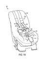
- FIG. 1A illustrates a child safety seat according to one embodiment of the present invention
- FIG. 1B illustrates a child safety seat according to one embodiment of the present invention
- FIG. 2A illustrates a front view of a buckle pad according to one embodiment of the present invention
- FIG. 2B illustrates a rear view of a buckle pad according to one embodiment of the present invention
- FIG. 2C illustrates a side view of a buckle assembly and seat portion according to one embodiment of the present invention
- FIG. 3 illustrates a biasing member of a buckle assembly according to one embodiment of the present invention
- FIG. 4 illustrates a cross-sectional view of the biasing member of the buckle assembly according to one embodiment of the present invention
- FIG. 5A illustrates a front view of a buckle pad including a buckle webbing opening according to one embodiment of the present invention
- FIG. 5B illustrates a rear view of the buckle pad of FIG. 5A according to one embodiment of the present invention
- FIG. 5C illustrates a side view of a buckle assembly including a buckle pad with a buckle webbing opening according to one embodiment of the present invention
- FIG. 6 illustrates a front view of a buckle pad according to one embodiment of the present invention
- FIG. 7 illustrates a front view of a buckle pad according to another embodiment of the present invention.
- FIG. 8 illustrates a portion of a child safety seat according to one embodiment of the present invention.
- a child safety seat may be configured for installation in a forward-facing position or in a reward-facing position to accommodate children in the appropriate position based on the height and weight of a child, such as according to the guidelines and standards of the United States National Highway Transportation Safety Administration (NHTSA) and similar authorities in other countries.
- NHSA National Highway Transportation Safety Administration
- child safety seats are usually securely attached to a fixed location within the vehicle, such as in accordance with the international standard for attachment points for child safety seats, ISOFIX, or using LATCH (Lower Anchors and Tethers for Children) attachments in the U.S.
- LATCH Lower Anchors and Tethers for Children
- the child safety seat harness is typically secured via a buckle to keep the child in the child safety seat while the vehicle is in motion.
- Some child safety seats may include a seat portion and a back portion.
- some child safety seats are positioned such that an edge of the seat portion of the child safety seat, which in some instances may include a buckle attached thereto, is angled upwards from a horizontal plane with respect to the opposite edge of the seat portion adjacent the back portion. Accordingly, when the buckle is not engaged with the harness, the buckle may be naturally biased (e.g., by gravity) inwardly towards the back portion of a child safety seat. As such, when placing a child in the child safety seat for use, the child may experience temporary discomfort when placed on top of the buckle.
- a user may find it difficult to locate and/or access the buckle when the child is sitting on the buckle, and the user may need to remove the child from the child safety seat to locate the buckle or at least shift the child in the seat, which may be difficult and/or time consuming.
- a child safety seat configured for attachment to a seat in a variety of vehicles. Additionally, some embodiments provide a child safety seat including a harness assembly that is configurable between an engaged state and a disengaged state. In the engaged state, a child occupying the child safety seat will be restrained in a secured fashion to the child safety seat, as described in greater detail below.
- the child safety seat 100 may include a back portion 102 and a seat portion 104, as illustrated in FIG. 1A .
- the seat portion 104 may be configured to receive a child thereon.
- the seat portion 104 may include an edge (not visible) disposed adjacent and/or coupled to an edge of the back portion 102.
- the back portion 102 may extend upwardly from the seat portion 104.
- the back portion 102 may extend upwardly from the seat portion 104 in a substantially perpendicular manner with respect to a horizontal plane.
- the child safety seat 100 may include a seat cover 140 configured to cover the seat portion 104 and back portion 102 of the child safety seat.
- a child may be placed in the child safety seat 100 such that the seat cover may be disposed between the child and the child safety seat 100.
- the child may be placed in the child safety seat 100 such that the child's upper body (e.g., the child's head, neck, and/or back) rests against the back portion 102 and the child's lower body (e.g., the child's posterior and legs) rests against the seat portion 104.
- the seat cover 140 may provide a cushioned support for the child's upper body and the child's lower body as the child rests against the back portion 102 and the seat portion 104, respectively.
- the child safety seat 100 may include a harness assembly 106.
- the harness assembly 106 may include shoulder straps 120.
- the harness assembly 106 may include buckle tabs 130 configured to engage a buckle 110 so as to secure the shoulder straps 120 to the buckle 110 in an engaged state.
- the harness assembly 106 may further include at least one buckle assembly 108 comprising a buckle 110 configured to receive the buckle tabs 130 for securing the shoulder straps 120 in the engaged state.
- the buckle assembly 108 may further include a buckle pad 114, wherein at least a portion of the buckle pad 114 is generally aligned with and adjacent to the buckle 110 and/or buckle webbing 112, as shown in FIGS. 1A and 2C .
- the buckle pad 114 may be adjacent to the buckle 110 such that the buckle pad 114 and the buckle 110 contact one another when the harness assembly is in the engaged state and a child occupies the child safety seat 100.
- a buckle pad 114 may be configured to provide cushioning between the buckle 110 and a child occupying the child safety seat.
- the buckle pad 114 may include cushioning material (e.g., foam, wadding, fabric, etc.) such that when the buckle assembly 108 and the harness assembly 106 are in the engaged state, a child occupying the seat experiences minimal discomfort from the buckle 110.
- the buckle assembly 108 may include a buckle webbing 112 extending from the buckle 110 and configured to attach the buckle 110 to the child safety seat 100.
- the buckle webbing 112 may be secured to the seat portion 104 of the child safety seat 100 via a buckle anchor 113 (shown in FIG. 2C ).
- the buckle webbing 112 may be configured to attach a buckle 110 to the child safety seat and may be configured to extend between a child's legs when the child occupies the child safety seat.
- the buckle webbing 112 comprises a single length of material that is anchored in one location (e.g., via the buckle anchor 113) to the seat portion 104.
- the buckle webbing may comprise a plurality of straps, such as two straps that are connected to the buckle 110 and are anchored to the seat portion 104 of the child safety seat at two or more locations (e.g., via two or more anchors).
- the buckle assembly 108 may include a biasing member 300, shown in FIG. 3 , engaged with the buckle pad 114 and configured to bias the buckle assembly 108, in an instance in which the harness assembly 106 is in the disengaged state, toward a first position located away from the back portion 102 of the child safety seat 100.
- the buckle assembly 108 may be biased away from the child towards a location between the child's legs and proximate to the seat portion 104.
- the biasing member 300 may be configured to bias the buckle assembly 108 forwardly along the direction of curved arrow A, as shown in FIG. 2C , when the buckle assembly 108 is disengaged from the shoulder straps 120.
- the coupling of the shoulder straps 120 to the buckle assembly 108 overcomes a forwardly biasing force configured to bias the buckle assembly 108 to the first position along the direction A.
- the buckle assembly 108 is depicted in an instance in which the biasing force is overcome (e.g., by a user attempting to engage the buckle 110 with the buckle tabs 130).
- the buckle assembly may be used with any seat (such as a high chair, stroller, etc.) so as to bias a buckle away from a back portion of the seat and/or clear the way for an occupant to be placed into the seat as described herein to facilitate use of the buckle and/or entry and removal of an occupant to the seat.
- any seat such as a high chair, stroller, etc.
- FIGS. 2A and 2B illustrate a buckle pad 114 according to an example embodiment of the present invention.
- FIG. 2A illustrates a front view of the buckle pad 114
- FIG. 2B illustrates a rear view of the buckle pad 114.
- the buckle pad 114 may have a lollipop shape as shown in FIGS. 2A and 2B .
- the buckle pad 114 may include a buckle pad head portion 202 and a buckle pad tail portion 204.
- FIGS. 2A and 2B as having a lollipop shape, one skilled in the art may appreciate that the buckle pad 114 may have any shape and/or size.
- the buckle pad head portion 202 may have a greater width than the buckle pad tail portion 204 (as shown) or the same width.
- the buckle pad tail portion 204 may have a greater length than the buckle pad head portion 202 (as depicted) or the same length as the buckle pad head portion 202 in some embodiments.
- FIGS. 2A and 2B illustrate the buckle pad head portion 202 having a substantially circular shape. In other embodiments, however, the head portion 202 may be substantially shaped as a rectangle, oval, and/or any other shape.
- the head portion 202 and the tail portion 204 may be shaped such that a longitudinal length of the tail portion 204 and/or head portion 202 is generally aligned with the buckle 110 and/or buckle webbing 112.
- the buckle pad 114 may include a head portion 202 generally aligned with the buckle 110, wherein the buckle pad 114 is disposed between a child occupying the child safety seat and the buckle 110.
- the buckle pad head portion 202 may be configured to provide a child occupying the child safety seat 100 with cushioning from the buckle 110.
- the head portion 202 may be disposed between the buckle 110 and the child while the harness assembly is in the engaged state such that a cushioning material disposed within the head portion 202 cushions the child from the buckle 110.
- the tail portion 204 may be generally aligned with the buckle webbing 112, such that the tail portion is disposed between the child occupying the child safety seat and the buckle webbing.
- the buckle tail portion 204 may be configured to provide the seated child with cushioning from the buckle webbing 112 while the harness assembly is in the engaged state.
- the buckle pad 114 may include a tail portion 204 configured to receive at least a portion of a biasing member 300 therein.
- the buckle pad 114 may, for example, include a biasing member pocket 208 that is disposed within the interior of buckle pad 114.
- the biasing member pocket 208 depicted via dashed lines in FIG. 2A , may be accessible from the front of the buckle pad 114 via a biasing member pocket opening 206.
- the biasing member pocket 208 may extend from the bottom of the buckle pad tail portion 204 to the buckle pad head portion 202.
- the biasing member pocket 208 may extend to the top of the buckle pad head portion 202.
- the biasing member pocket 208 may extend to approximately one-half of the length of the buckle pad head portion 202, whereas in still other embodiments, the biasing member pocket 208 may extend to less than one-half of the length of the buckle pad head portion 202 (as depicted) or may be housed entirely within the buckle pad tail portion 204.
- the buckle pad 114 may further include a buckle strap 210.
- the buckle strap 210 may be coupled to the exterior surface of the buckle pad 114.
- the buckle strap 210 may be coupled to the exterior surface of the buckle pad 114 such that the buckle strap 210 and the exterior surface of the buckle pad 114 form a passageway therebetween.
- the passageway between the buckle strap 210 and the buckle pad 114 may be configured to allow a buckle webbing 112, shown in FIG. 1A , to travel therethrough.
- the buckle strap 210 may be configured to receive the buckle webbing 112 therethrough such that when a biasing force is applied to the buckle pad 114 by the biasing member 300, the biasing force may also be applied to the buckle webbing 112 and/or the buckle 110 (e.g., the buckle assembly 108 as a whole).
- the biasing member 300 may be configured to move the buckle assembly 108 to the first position (shown in Fig. 2C ), wherein the first position is adjacent the seat portion 104 and away from the back portion 102.
- the biasing member 300 may be configured to apply a biasing force so as to move the buckle assembly to a first position adjacent the seat portion 104 and away from the back portion 102 when the harness assembly 106 is in the disengaged state.
- the first position may be located forward of a second position (shown in FIG. 1A ), wherein the second position is defined by the position of the buckle when the harness is in the engaged state (e.g., when the shoulder straps 120 are engaged with the buckle assembly 108).
- the second position may be defined as a position adjacent to the position of a child occupying the seat, such as when the harness assembly 106 is in the engaged state.
- the buckle pad 114 may include an edging 212 that surrounds the perimeter of the buckle pad 114, as shown in FIG. 2B .
- the buckle strap 210 may be coupled to the buckle pad 114 by placing a portion of the buckle strap 210 underneath the edging 212 and by securing the edging 212 to the perimeter of the buckle pad 114 with a stitching, adhesive, and/or the like.
- the buckle strap 210 may be coupled to the buckle pad 114 by securing the buckle strap 210 directly to the material forming the buckle pad 114 with a stitching, adhesive, and/or the like.
- the buckle strap 210 may be integral to the buckle pad 114.
- the buckle pad 114 may include a fabric covering that is slitted such that the slitted portion of the buckle pad covering forms the buckle strap 210.
- FIGS. 5A and 5B illustrate a buckle pad 514 according to another example embodiment of the present invention.
- FIG. 5A illustrates a front view of the buckle pad 514
- FIG. 5B illustrates a rear view of the buckle pad 514.
- the buckle pad 514 may include a buckle pad head portion 502 and a buckle pad tail portion 504.
- the buckle pad 514 may have any shape and/or size.
- the buckle pad head portion 502 may have a greater width than the buckle pad tail portion 504 (as shown) or the same width.
- the buckle pad tail portion 504 may have a greater length than the buckle pad head portion 502 (as depicted) or the same length as the buckle pad head portion 502 in some embodiments.
- FIGS. 5A and 5B illustrate the buckle pad head portion 502 having a substantially circular shape. In other embodiments, however, the head portion 502 may be substantially shaped as a rectangle, oval, and/or any other shape.
- the buckle pad head portion 502 and the buckle pad tail portion 504 may be shaped such that a longitudinal length of the buckle pad tail portion 504 and/or the buckle pad head portion 502 is generally aligned with a buckle 110 and/or buckle webbing 112.
- the buckle pad head portion 502 may further include a buckle webbing opening 516 that extends completely through the buckle pad 514.
- the buckle webbing opening 516 may be configured to receive a buckle webbing 112 therethrough, as shown in FIGS. 1B and 5C .
- a portion of the buckle webbing 112 may be disposed in front of the buckle pad 514 and a portion of the buckle webbing 112 may be disposed behind the buckle pad 514.
- the buckle webbing 112 may be coupled to the buckle via a buckle opening 111 configured to receive the buckle webbing 112 therethrough (as shown in FIG. 8 ).
- the buckle webbing 112 may include a first end and a second end, wherein each of the first and second ends may be secured to the seat portion 104 of the child safety seat 100 via a respective buckle anchor 113 (as shown in FIG. 5C ).
- the first end and second end of the buckle webbing 112 may be secured to the seat portion 104 at a location disposed on either side of the buckle pad 514, as illustrated in FIG. 1B .
- a buckle assembly 108 may include a first and second buckle webbing 112, wherein each of the buckle webbings includes a first end and a second end.
- each of the first and second buckle webbing 112 may be coupled to the buckle 110 at a first end of the respective first and second buckle webbing 112 and may be secured to the seat portion 104 of the child safety seat 100 at the second end of the respective first and second buckle webbing 112.
- the buckle pad 514 may be configured to engage a first and second buckle webbing so as to bias a buckle assembly to a first position adjacent to the seat portion when the harness assembly 106 is in the disengaged state.
- the buckle pad head portion 504 may be generally aligned with the buckle 110, wherein the buckle pad head portion 504 is disposed between a child occupying the child safety seat and the buckle 110.
- the buckle pad head portion 502 may be configured to provide a child occupying the child safety seat 100 with cushioning from the buckle 110.
- the buckle pad head portion 502 may be disposed between the buckle 110 and the child while the harness assembly is in the engaged state such that a cushioning material disposed within the head portion 502 cushions the child from the buckle 110.
- the buckle assembly 108 may include a biasing member 300, shown in FIG. 3 , engaged with the buckle pad 514 and configured to bias the buckle assembly 108, in an instance in which the harness assembly 106 is in the disengaged state, toward a first position located away from the back portion 102 of the child safety seat 100.
- the buckle assembly 108 may be configured to bias the buckle pad 514 to a first position adjacent the seat portion 104 and away from the location of a seated child and/or a back portion 102 of the child seat 100, in the direction A, when the harness assembly 106 is in the disengaged state, as shown in FIG. 5C .
- the buckle assembly 108 may be biased away from the child towards a location between the child's legs and proximate to the seat portion 104 when the harness assembly 106 is in the disengaged state.
- the first position may be located forward of a second position (shown in FIGS. 1A and 1B ), wherein the second position is defined by the position of the buckle when the harness is in the engaged state (e.g., when the shoulder straps 120 are engaged with the buckle assembly 108).
- the second position may be defined as a position adjacent to the position of a child occupying the seat, such as when the harness assembly 106 is in the engaged state.
- the buckle pad 514 may include a tail portion 504 configured to receive at least a portion of a biasing member 300 therein.
- the buckle pad 514 may, for example, include a biasing member pocket 508 that is disposed within the interior of buckle pad 514.
- the biasing member pocket 508, depicted via dashed lines in FIG. 5A may be accessible from the front of the buckle pad 514 via a biasing member pocket opening 506.
- the biasing member pocket 508 may extend from the bottom of the buckle pad tail portion 504 and into the buckle pad head portion 502.
- the biasing member pocket 508 may extend from the bottom of the buckle pad tail portion 504 toward the bottom of the buckle webbing opening 516 disposed within the buckle pad head portion 502, as shown in FIG. 5A .
- the biasing member pocket 508 may extend from the bottom of the buckle pad tail portion 504 to above the buckle webbing opening 516 disposed within the buckle pad head portion 502.
- the biasing member pocket 508 may substantially surround and be partially defined by the buckle webbing opening 516.
- the biasing member pocket 508 may further include an upper portion 509 above the buckle webbing opening 516.
- the biasing member 300 may be disposed within the biasing member pocket 508 and the upper portion 509 such that the biasing member 300 is disposed above and below the buckle webbing opening 516, such as in embodiments in which the biasing member is configured in a loop, as shown in FIG. 3 .
- the buckle assembly 108 may comprise a biasing member 300, as shown in FIG. 3 .
- the biasing member 300 may be formed by taking a fixed length of material, such as a metal, plastic, composite plastic, elastic, fibrous, or any other resilient material that has a tendency to return to its original shape or position, and coupling one end of the material to an opposite end of the material, thereby forming a closed loop.
- the biasing member 300 may include a length of material 302 having a 7x7 stainless steel braided core construction, as shown in FIG. 4 .
- the braided strands of material 302 may comprise stainless steel having an SAE grade of 304.
- the material 302 may have a length of approximately between 16 and 20 inches, such as approximately 18 inches. Additionally and/or alternatively, the braided material 302 may have a maximum diameter of approximately between 0.07 inches and 0.11 inches, such as approximately 0.09 inches.
- the biasing member 300 may be formed by taking a fixed length of material 302 and coupling one end of the material to an opposite end of the material with a coupling element 304 to form the loop, as illustrated in FIG. 3 .
- the coupling element 304 may be configured to couple opposing ends of the braided strands of material 302 to each other.
- the coupling element 304 may comprise stainless steel, aluminum, or any other material suited to form a coupling element to couple one end of the length of material 302 to the opposite end of the length of material 302, such as via a threaded connection, clips, and/or other mechanical connection.
- the ends of the material 302 may be welded, adhered, or otherwise held together without a coupling element 304.
- the biasing member 300 may be configured to be inserted into the biasing member pocket 208 of the buckle pad 114 via the biasing member pocket opening 206 ( FIG. 2A ).
- the biasing member 300 may be configured to be inserted into the biasing member pocket 208 of the buckle pad 114 in a coupled state.
- the biasing member 300 may be configured to extend along an interior perimeter of the biasing member pocket 208 when the pre-coupled biasing member 300 is inserted therein.
- the perimeter of the biasing member pocket 208 may be substantially similar to the length of the closed loop of the biasing member 300, and the biasing member 300 may be made of a material that, when formed into the loop, is configured to exert an outward force (e.g., away from a center of the loop) such that the biasing member maintains its shape and/or has a tendency to assume the shape of the biasing member pocket 208 in which it is held.
- an outward force e.g., away from a center of the loop
- the biasing member 300 may be configured to be inserted into the biasing member pocket 508 and an upper portion 509 of the biasing member pocket 508 of a buckle pad 114 via the biasing member pocket opening 506, as shown in FIG. 6 .
- the length of material 302 of the biasing member 300 may be configured to first be positioned within the biasing member pocket 508 and the upper portion 509 in an uncoupled state. Once the length of material 302 occupies the upper portion 509, a first end and an opposite end of the length of material 302 may be coupled together to form the closed loop.
- one end of the length of material 302 may be inserted into the biasing member pocket opening and guided towards the buckle pad head portion 502.
- the length of material 302 may be guided upwards towards the buckle webbing opening 516 and may be guided into the upper portion 509 from one side of the buckle webbing opening and may be guided from the upper portion 509 back down the biasing member pocket 508 (e.g., into the buckle pad tail portion 504) from the other side of the buckle webbing opening.
- a first end of the biasing member may be coupled to the opposite end of the biasing member 300 with a coupling element 304 (e.g., via the biasing member opening pocket 506) so as to form the closed loop of material.
- the coupling element 304 may be cylindrical in shape and may be configured to receive each of the opposing ends of the length of braided material 302 therein.
- the coupling element 304 may have a length of approximately between 0.6 inches and 1 inch, such as approximately 0.8 inches, and a maximum outer diameter of approximately between 0.15 inches and 0.19 inches, such as approximately 0.17 inches.
- the coupling element 304 may be configured to be deformed by an external force so as to create a butt end joint with the braided material 302.
- the coupling element 304 may be crimped, adhered, welded, or otherwise fixed to the ends of the material 302 to form a closed loop biasing member 300.
- the biasing member 300 may be shaped as a solid tongue strip 306, depicted via the dashed lines in FIG. 7 .
- the biasing member 300 may be inserted within the biasing member pocket 208, 508 via the biasing member pocket opening 206, 506, as shown in FIGS. 2A and 5A respectively.
- the biasing member 300, such as the solid tongue strip 306, may be configured to bias the buckle pad 114, 514, when inserted therein, to fold away from the location of a seated child and/or a back portion of the child seat, in the direction A, when the harness assembly 106 is in the disengaged state, as shown in FIGS. 2C , 5C .
- the particular configuration of the biasing member 300 may vary, however, depending on the amount of biasing force needed to overcome the force of gravity to move the buckle assembly 108 toward a first position away from an occupant of the child safety seat 100 in the disengaged state.
- the amount of biasing force may depend, at least in part, on the angle at which the seat portion 104 is joined to the back portion 102 of the child safety seat 100 and the resulting angle of the seat portion with respect to the horizontal plane.
- the angle between the seat portion 104 and the horizontal plane may be around 45°, whereas in a seat for an older child (e.g., a convertible car seat), the angle between the seat portion 104 and the horizontal plane may be only about 10°-15°.
- the buckle assembly may include a buckle pad, a buckle, and a biasing member.
- the buckle pad may include a wadding to provide a cushioned layer between a child occupant and the buckle. Additionally and/or alternatively, the wadding may be placed within the interior of a fabric defining the surface of the buckle pad. In some embodiments, the wadding may have an areal density of approximately 260 grams per square meter. The wadding may define a width of approximately 32 mm.
- the buckle pad may include a buckle pad tail portion and a buckle pad head portion.
- the buckle pad may be approximately 11.5 inches in length.
- the buckle pad head portion may be approximately 4.25 inches in length, and the buckle pad tail portion may be approximately 7.25 inches in length. Further, the buckle pad tail portion may be approximately 2.38 inches in width.
- the buckle pad head portion may be substantially circular in shape and may have a diameter of approximately 4.25 inches in length. In other embodiments, the buckle pad head portion may be elliptical in shape and have a minor axis of approximately 4.25 inches and a major axis of approximately 5 inches.
- the buckle pad may include a biasing member pocket that extends from a distal end of the buckle pad tail portion into the buckle pad head portion.
- the biasing member pocket may be configured to receive a biasing member therein, wherein the biasing member comprises a closed loop of material, such as a braided steel rope.
- the biasing member pocket may have a width of approximately 2 inches and a length of approximately 8.56 inches.
- the buckle pad 114 and the biasing member 300 may be configured to be placed between a seat portion 104 of the child safety seat 100 and a seat cover 140.
- a buckle anchor may be configured to be coupled to the child safety seat 100.
- a buckle anchor 113 shown in FIG. 2C
- the buckle anchor may be coupled to the seat portion of the child safety seat so as to attach the buckle assembly 108 to the child safety seat 100.
- the buckle webbing 112 may be configured to secure the buckle assembly 108 to the child safety seat 100.
- the buckle pad 114 when viewed from the front of the child safety seat 100, the buckle pad 114 may be disposed behind the buckle webbing 112, buckle 110, and/or buckle anchor 113 (shown in FIG. 2C ), so as to be located between an occupant of the seat and the buckle and buckle webbing. In some embodiments, the buckle pad 114 may have a greater length than the combination of the buckle 110 and buckle webbing 112, such that when the buckle anchor 113 is coupled to the child safety seat 100, a portion of the buckle pad tail portion 204 may extend from the position where the buckle anchor is coupled to the seat portion 104 of the child safety seat 100 towards the back portion 102 of the child safety seat 100.
- a portion of the buckle pad 114 may be disposed between the seat portion 104 of the child safety seat 100 and the child safety seat cover 140 (e.g., under the seat cover), as illustrated in FIG. 2C .
- the biasing member 300 may be configured to provide a biasing force to the buckle assembly 108 to position the buckle assembly forwardly toward a first position located away from the back portion 102 and towards the seat portion 104 when the harness assembly 106 is in a disengaged state, as shown in FIG. 2C .
- the biasing member 300 may be configured to provide a biasing force to the buckle assembly 108 such that the buckle assembly 108 is biased toward the first position located away from an occupant when the harness assembly 106 is in a disengaged state.
Landscapes
- Engineering & Computer Science (AREA)
- Mechanical Engineering (AREA)
- Health & Medical Sciences (AREA)
- Child & Adolescent Psychology (AREA)
- General Health & Medical Sciences (AREA)
- Aviation & Aerospace Engineering (AREA)
- Transportation (AREA)
- Seats For Vehicles (AREA)
- Automotive Seat Belt Assembly (AREA)
Applications Claiming Priority (2)
| Application Number | Priority Date | Filing Date | Title |
|---|---|---|---|
| US13/467,710 US9114738B2 (en) | 2012-05-09 | 2012-05-09 | Flip forward buckle assembly |
| US201261715014P | 2012-10-17 | 2012-10-17 |
Publications (3)
| Publication Number | Publication Date |
|---|---|
| EP2662233A2 true EP2662233A2 (de) | 2013-11-13 |
| EP2662233A3 EP2662233A3 (de) | 2017-10-11 |
| EP2662233B1 EP2662233B1 (de) | 2021-12-01 |
Family
ID=48190669
Family Applications (1)
| Application Number | Title | Priority Date | Filing Date |
|---|---|---|---|
| EP13002088.6A Active EP2662233B1 (de) | 2012-05-09 | 2013-04-22 | Vorklapp-Schnallenanordnung |
Country Status (6)
| Country | Link |
|---|---|
| EP (1) | EP2662233B1 (de) |
| KR (1) | KR101398840B1 (de) |
| CN (1) | CN103287384B (de) |
| AU (1) | AU2013100453A4 (de) |
| CA (1) | CA2815420C (de) |
| NZ (1) | NZ609763A (de) |
Families Citing this family (3)
| Publication number | Priority date | Publication date | Assignee | Title |
|---|---|---|---|---|
| CN104325962A (zh) * | 2014-10-28 | 2015-02-04 | 好孩子儿童用品有限公司 | 儿童汽车座的安全带结构 |
| CN213565524U (zh) | 2020-08-24 | 2021-06-29 | 宝钜瑞士股份有限公司 | 扣具固定装置及含该扣具固定装置的安全座椅 |
| CN116654074A (zh) * | 2022-02-21 | 2023-08-29 | 明门(中国)幼童用品有限公司 | 儿童座椅及儿童载具 |
Family Cites Families (8)
| Publication number | Priority date | Publication date | Assignee | Title |
|---|---|---|---|---|
| JPH06286509A (ja) * | 1993-04-02 | 1994-10-11 | Suzuki Motor Corp | 子供用シート付自動車用シート |
| JP3345463B2 (ja) * | 1993-06-16 | 2002-11-18 | アップリカ▲葛▼西株式会社 | 自動車用子供安全シート |
| JP2001114000A (ja) | 1999-10-18 | 2001-04-24 | Tachi S Co Ltd | チャイルド・シート機能付き乗り物シート |
| US6779843B2 (en) | 2002-12-27 | 2004-08-24 | Cosco Management, Inc. | Harness-control panel adjuster for child-restraint seat |
| KR20060021818A (ko) * | 2003-04-18 | 2006-03-08 | 아프리카 이쿠지켄큐카이 아프리카 카사이 가부시키가이샤 | 육아 기구의 좌석 |
| US7644986B2 (en) * | 2006-03-09 | 2010-01-12 | Skjp Holdings, Llc | Child restraint device with energy absorbing regions |
| US8038214B2 (en) * | 2009-02-11 | 2011-10-18 | Cosco Management, Inc. | Harness system for juvenile vehicle seat |
| CN101954897A (zh) * | 2009-07-13 | 2011-01-26 | 明门香港股份有限公司 | 儿童汽车椅及其弹性胯带 |
-
2013
- 2013-04-10 AU AU2013100453A patent/AU2013100453A4/en not_active Ceased
- 2013-04-22 EP EP13002088.6A patent/EP2662233B1/de active Active
- 2013-04-30 NZ NZ609763A patent/NZ609763A/en not_active IP Right Cessation
- 2013-05-03 KR KR1020130050063A patent/KR101398840B1/ko active Active
- 2013-05-08 CN CN201310166795.9A patent/CN103287384B/zh active Active
- 2013-05-08 CA CA2815420A patent/CA2815420C/en active Active
Non-Patent Citations (1)
| Title |
|---|
| None |
Also Published As
| Publication number | Publication date |
|---|---|
| CN103287384B (zh) | 2015-11-18 |
| NZ609763A (en) | 2014-05-30 |
| CA2815420C (en) | 2015-11-17 |
| AU2013100453A4 (en) | 2013-05-23 |
| KR20130125719A (ko) | 2013-11-19 |
| CN103287384A (zh) | 2013-09-11 |
| EP2662233B1 (de) | 2021-12-01 |
| EP2662233A3 (de) | 2017-10-11 |
| KR101398840B1 (ko) | 2014-05-27 |
| CA2815420A1 (en) | 2013-11-09 |
Similar Documents
| Publication | Publication Date | Title |
|---|---|---|
| US9114738B2 (en) | Flip forward buckle assembly | |
| KR101348542B1 (ko) | 유아시트 겸용 자동차 시트커버 | |
| US8251457B2 (en) | Child restraint safety device | |
| US8210617B2 (en) | Child restraint system | |
| US6363558B1 (en) | Infant support with an improved securement device | |
| US8534757B2 (en) | Child safety seat and its installation method | |
| JP2004090907A (ja) | 自動車用子供座席 | |
| US9981629B2 (en) | Child restraint system for use in vehicles | |
| CN105034876A (zh) | 安全带夹 | |
| KR101716568B1 (ko) | 어린이 안전시트로 사용가능한 차량용 보조시트 | |
| US20050268381A1 (en) | Wearable side impact protector | |
| EP2662233B1 (de) | Vorklapp-Schnallenanordnung | |
| US20150239426A1 (en) | Safety belt retention device | |
| CA2806574A1 (en) | An attachment device for a seatbelt restraint system to be used by pregnant women and other passengers | |
| EP2847034B1 (de) | Gurtschutz-sischerheitssystem | |
| AU2013101560B4 (en) | Flip forward buckle assembly | |
| NZ569461A (en) | Car seat pillow for a childs car seat with two lateral portions connected by intermediate portion and retained in use between child seat and vehicle seat or to seat belt | |
| KR102269951B1 (ko) | 어린이용 안전벨트 쿠션장치 | |
| CN205769165U (zh) | 一种机动车儿童乘员用约束系统 | |
| KR102201179B1 (ko) | 차량 좌석의 등받이와 안전시트 등받이 사이의 공간이 벌이지지 않게 고정되어 안전성이 향상된 안전시트. | |
| TWI824704B (zh) | 兒童座椅 | |
| AU2009100445B4 (en) | A connector for securing a tether strap of a child safety seat | |
| CN107444332A (zh) | 一种机动车儿童乘员用约束系统 | |
| AU2013245547A1 (en) | Child restraint for a vehicle | |
| JP2006232116A (ja) | 幼児拘束装置 |
Legal Events
| Date | Code | Title | Description |
|---|---|---|---|
| PUAI | Public reference made under article 153(3) epc to a published international application that has entered the european phase |
Free format text: ORIGINAL CODE: 0009012 |
|
| AK | Designated contracting states |
Kind code of ref document: A2 Designated state(s): AL AT BE BG CH CY CZ DE DK EE ES FI FR GB GR HR HU IE IS IT LI LT LU LV MC MK MT NL NO PL PT RO RS SE SI SK SM TR |
|
| AX | Request for extension of the european patent |
Extension state: BA ME |
|
| PUAL | Search report despatched |
Free format text: ORIGINAL CODE: 0009013 |
|
| AK | Designated contracting states |
Kind code of ref document: A3 Designated state(s): AL AT BE BG CH CY CZ DE DK EE ES FI FR GB GR HR HU IE IS IT LI LT LU LV MC MK MT NL NO PL PT RO RS SE SI SK SM TR |
|
| AX | Request for extension of the european patent |
Extension state: BA ME |
|
| RIC1 | Information provided on ipc code assigned before grant |
Ipc: B60N 2/26 20060101AFI20170905BHEP |
|
| STAA | Information on the status of an ep patent application or granted ep patent |
Free format text: STATUS: REQUEST FOR EXAMINATION WAS MADE |
|
| 17P | Request for examination filed |
Effective date: 20180329 |
|
| RBV | Designated contracting states (corrected) |
Designated state(s): AL AT BE BG CH CY CZ DE DK EE ES FI FR GB GR HR HU IE IS IT LI LT LU LV MC MK MT NL NO PL PT RO RS SE SI SK SM TR |
|
| GRAP | Despatch of communication of intention to grant a patent |
Free format text: ORIGINAL CODE: EPIDOSNIGR1 |
|
| STAA | Information on the status of an ep patent application or granted ep patent |
Free format text: STATUS: GRANT OF PATENT IS INTENDED |
|
| INTG | Intention to grant announced |
Effective date: 20210622 |
|
| GRAS | Grant fee paid |
Free format text: ORIGINAL CODE: EPIDOSNIGR3 |
|
| GRAA | (expected) grant |
Free format text: ORIGINAL CODE: 0009210 |
|
| STAA | Information on the status of an ep patent application or granted ep patent |
Free format text: STATUS: THE PATENT HAS BEEN GRANTED |
|
| RBV | Designated contracting states (corrected) |
Designated state(s): AL AT BG CY CZ DE DK EE ES FI FR GB GR HR HU IS IT LT LV MK NL NO PL PT RO RS SE SI SK SM TR |
|
| AK | Designated contracting states |
Kind code of ref document: B1 Designated state(s): AL AT BG CY CZ DE DK EE ES FI FR GB GR HR HU IS IT LT LV MK NL NO PL PT RO RS SE SI SK SM TR |
|
| REG | Reference to a national code |
Ref country code: GB Ref legal event code: FG4D |
|
| REG | Reference to a national code |
Ref country code: AT Ref legal event code: REF Ref document number: 1451457 Country of ref document: AT Kind code of ref document: T Effective date: 20211215 |
|
| REG | Reference to a national code |
Ref country code: DE Ref legal event code: R096 Ref document number: 602013080238 Country of ref document: DE |
|
| REG | Reference to a national code |
Ref country code: LT Ref legal event code: MG9D |
|
| REG | Reference to a national code |
Ref country code: NL Ref legal event code: MP Effective date: 20211201 |
|
| REG | Reference to a national code |
Ref country code: AT Ref legal event code: MK05 Ref document number: 1451457 Country of ref document: AT Kind code of ref document: T Effective date: 20211201 |
|
| PG25 | Lapsed in a contracting state [announced via postgrant information from national office to epo] |
Ref country code: RS Free format text: LAPSE BECAUSE OF FAILURE TO SUBMIT A TRANSLATION OF THE DESCRIPTION OR TO PAY THE FEE WITHIN THE PRESCRIBED TIME-LIMIT Effective date: 20211201 Ref country code: LT Free format text: LAPSE BECAUSE OF FAILURE TO SUBMIT A TRANSLATION OF THE DESCRIPTION OR TO PAY THE FEE WITHIN THE PRESCRIBED TIME-LIMIT Effective date: 20211201 Ref country code: FI Free format text: LAPSE BECAUSE OF FAILURE TO SUBMIT A TRANSLATION OF THE DESCRIPTION OR TO PAY THE FEE WITHIN THE PRESCRIBED TIME-LIMIT Effective date: 20211201 Ref country code: BG Free format text: LAPSE BECAUSE OF FAILURE TO SUBMIT A TRANSLATION OF THE DESCRIPTION OR TO PAY THE FEE WITHIN THE PRESCRIBED TIME-LIMIT Effective date: 20220301 Ref country code: AT Free format text: LAPSE BECAUSE OF FAILURE TO SUBMIT A TRANSLATION OF THE DESCRIPTION OR TO PAY THE FEE WITHIN THE PRESCRIBED TIME-LIMIT Effective date: 20211201 |
|
| PG25 | Lapsed in a contracting state [announced via postgrant information from national office to epo] |
Ref country code: SE Free format text: LAPSE BECAUSE OF FAILURE TO SUBMIT A TRANSLATION OF THE DESCRIPTION OR TO PAY THE FEE WITHIN THE PRESCRIBED TIME-LIMIT Effective date: 20211201 Ref country code: PL Free format text: LAPSE BECAUSE OF FAILURE TO SUBMIT A TRANSLATION OF THE DESCRIPTION OR TO PAY THE FEE WITHIN THE PRESCRIBED TIME-LIMIT Effective date: 20211201 Ref country code: NO Free format text: LAPSE BECAUSE OF FAILURE TO SUBMIT A TRANSLATION OF THE DESCRIPTION OR TO PAY THE FEE WITHIN THE PRESCRIBED TIME-LIMIT Effective date: 20220301 Ref country code: LV Free format text: LAPSE BECAUSE OF FAILURE TO SUBMIT A TRANSLATION OF THE DESCRIPTION OR TO PAY THE FEE WITHIN THE PRESCRIBED TIME-LIMIT Effective date: 20211201 Ref country code: HR Free format text: LAPSE BECAUSE OF FAILURE TO SUBMIT A TRANSLATION OF THE DESCRIPTION OR TO PAY THE FEE WITHIN THE PRESCRIBED TIME-LIMIT Effective date: 20211201 Ref country code: GR Free format text: LAPSE BECAUSE OF FAILURE TO SUBMIT A TRANSLATION OF THE DESCRIPTION OR TO PAY THE FEE WITHIN THE PRESCRIBED TIME-LIMIT Effective date: 20220302 Ref country code: ES Free format text: LAPSE BECAUSE OF FAILURE TO SUBMIT A TRANSLATION OF THE DESCRIPTION OR TO PAY THE FEE WITHIN THE PRESCRIBED TIME-LIMIT Effective date: 20211201 |
|
| PG25 | Lapsed in a contracting state [announced via postgrant information from national office to epo] |
Ref country code: NL Free format text: LAPSE BECAUSE OF FAILURE TO SUBMIT A TRANSLATION OF THE DESCRIPTION OR TO PAY THE FEE WITHIN THE PRESCRIBED TIME-LIMIT Effective date: 20211201 |
|
| PG25 | Lapsed in a contracting state [announced via postgrant information from national office to epo] |
Ref country code: SM Free format text: LAPSE BECAUSE OF FAILURE TO SUBMIT A TRANSLATION OF THE DESCRIPTION OR TO PAY THE FEE WITHIN THE PRESCRIBED TIME-LIMIT Effective date: 20211201 Ref country code: SK Free format text: LAPSE BECAUSE OF FAILURE TO SUBMIT A TRANSLATION OF THE DESCRIPTION OR TO PAY THE FEE WITHIN THE PRESCRIBED TIME-LIMIT Effective date: 20211201 Ref country code: RO Free format text: LAPSE BECAUSE OF FAILURE TO SUBMIT A TRANSLATION OF THE DESCRIPTION OR TO PAY THE FEE WITHIN THE PRESCRIBED TIME-LIMIT Effective date: 20211201 Ref country code: PT Free format text: LAPSE BECAUSE OF FAILURE TO SUBMIT A TRANSLATION OF THE DESCRIPTION OR TO PAY THE FEE WITHIN THE PRESCRIBED TIME-LIMIT Effective date: 20220401 Ref country code: EE Free format text: LAPSE BECAUSE OF FAILURE TO SUBMIT A TRANSLATION OF THE DESCRIPTION OR TO PAY THE FEE WITHIN THE PRESCRIBED TIME-LIMIT Effective date: 20211201 Ref country code: CZ Free format text: LAPSE BECAUSE OF FAILURE TO SUBMIT A TRANSLATION OF THE DESCRIPTION OR TO PAY THE FEE WITHIN THE PRESCRIBED TIME-LIMIT Effective date: 20211201 |
|
| REG | Reference to a national code |
Ref country code: DE Ref legal event code: R097 Ref document number: 602013080238 Country of ref document: DE |
|
| PG25 | Lapsed in a contracting state [announced via postgrant information from national office to epo] |
Ref country code: IS Free format text: LAPSE BECAUSE OF FAILURE TO SUBMIT A TRANSLATION OF THE DESCRIPTION OR TO PAY THE FEE WITHIN THE PRESCRIBED TIME-LIMIT Effective date: 20220401 |
|
| PLBE | No opposition filed within time limit |
Free format text: ORIGINAL CODE: 0009261 |
|
| STAA | Information on the status of an ep patent application or granted ep patent |
Free format text: STATUS: NO OPPOSITION FILED WITHIN TIME LIMIT |
|
| PG25 | Lapsed in a contracting state [announced via postgrant information from national office to epo] |
Ref country code: DK Free format text: LAPSE BECAUSE OF FAILURE TO SUBMIT A TRANSLATION OF THE DESCRIPTION OR TO PAY THE FEE WITHIN THE PRESCRIBED TIME-LIMIT Effective date: 20211201 Ref country code: AL Free format text: LAPSE BECAUSE OF FAILURE TO SUBMIT A TRANSLATION OF THE DESCRIPTION OR TO PAY THE FEE WITHIN THE PRESCRIBED TIME-LIMIT Effective date: 20211201 |
|
| 26N | No opposition filed |
Effective date: 20220902 |
|
| PG25 | Lapsed in a contracting state [announced via postgrant information from national office to epo] |
Ref country code: SI Free format text: LAPSE BECAUSE OF FAILURE TO SUBMIT A TRANSLATION OF THE DESCRIPTION OR TO PAY THE FEE WITHIN THE PRESCRIBED TIME-LIMIT Effective date: 20211201 |
|
| PG25 | Lapsed in a contracting state [announced via postgrant information from national office to epo] |
Ref country code: IT Free format text: LAPSE BECAUSE OF FAILURE TO SUBMIT A TRANSLATION OF THE DESCRIPTION OR TO PAY THE FEE WITHIN THE PRESCRIBED TIME-LIMIT Effective date: 20211201 |
|
| PG25 | Lapsed in a contracting state [announced via postgrant information from national office to epo] |
Ref country code: HU Free format text: LAPSE BECAUSE OF FAILURE TO SUBMIT A TRANSLATION OF THE DESCRIPTION OR TO PAY THE FEE WITHIN THE PRESCRIBED TIME-LIMIT; INVALID AB INITIO Effective date: 20130422 |
|
| PG25 | Lapsed in a contracting state [announced via postgrant information from national office to epo] |
Ref country code: MK Free format text: LAPSE BECAUSE OF FAILURE TO SUBMIT A TRANSLATION OF THE DESCRIPTION OR TO PAY THE FEE WITHIN THE PRESCRIBED TIME-LIMIT Effective date: 20211201 Ref country code: CY Free format text: LAPSE BECAUSE OF FAILURE TO SUBMIT A TRANSLATION OF THE DESCRIPTION OR TO PAY THE FEE WITHIN THE PRESCRIBED TIME-LIMIT Effective date: 20211201 |
|
| PGFP | Annual fee paid to national office [announced via postgrant information from national office to epo] |
Ref country code: DE Payment date: 20250417 Year of fee payment: 13 |
|
| PGFP | Annual fee paid to national office [announced via postgrant information from national office to epo] |
Ref country code: FR Payment date: 20250422 Year of fee payment: 13 |
|
| PG25 | Lapsed in a contracting state [announced via postgrant information from national office to epo] |
Ref country code: TR Free format text: LAPSE BECAUSE OF FAILURE TO SUBMIT A TRANSLATION OF THE DESCRIPTION OR TO PAY THE FEE WITHIN THE PRESCRIBED TIME-LIMIT Effective date: 20211201 |
|
| PGFP | Annual fee paid to national office [announced via postgrant information from national office to epo] |
Ref country code: GB Payment date: 20260324 Year of fee payment: 14 |