EP2660828A1 - Apparatus comprising thermal fuse and resistor - Google Patents
Apparatus comprising thermal fuse and resistor Download PDFInfo
- Publication number
- EP2660828A1 EP2660828A1 EP11853301.7A EP11853301A EP2660828A1 EP 2660828 A1 EP2660828 A1 EP 2660828A1 EP 11853301 A EP11853301 A EP 11853301A EP 2660828 A1 EP2660828 A1 EP 2660828A1
- Authority
- EP
- European Patent Office
- Prior art keywords
- resistor
- thermal fuse
- wirewound
- device combining
- lead wire
- Prior art date
- Legal status (The legal status is an assumption and is not a legal conclusion. Google has not performed a legal analysis and makes no representation as to the accuracy of the status listed.)
- Granted
Links
Images


Classifications
-
- H—ELECTRICITY
- H01—ELECTRIC ELEMENTS
- H01H—ELECTRIC SWITCHES; RELAYS; SELECTORS; EMERGENCY PROTECTIVE DEVICES
- H01H85/00—Protective devices in which the current flows through a part of fusible material and this current is interrupted by displacement of the fusible material when this current becomes excessive
- H01H85/0039—Means for influencing the rupture process of the fusible element
- H01H85/0047—Heating means
- H01H85/0052—Fusible element and series heating means or series heat dams
-
- H—ELECTRICITY
- H01—ELECTRIC ELEMENTS
- H01C—RESISTORS
- H01C1/00—Details
- H01C1/08—Cooling, heating or ventilating arrangements
-
- H—ELECTRICITY
- H01—ELECTRIC ELEMENTS
- H01C—RESISTORS
- H01C1/00—Details
- H01C1/14—Terminals or tapping points or electrodes specially adapted for resistors; Arrangements of terminals or tapping points or electrodes on resistors
-
- H—ELECTRICITY
- H01—ELECTRIC ELEMENTS
- H01C—RESISTORS
- H01C13/00—Resistors not provided for elsewhere
-
- H—ELECTRICITY
- H01—ELECTRIC ELEMENTS
- H01C—RESISTORS
- H01C3/00—Non-adjustable metal resistors made of wire or ribbon, e.g. coiled, woven or formed as grids
- H01C3/14—Non-adjustable metal resistors made of wire or ribbon, e.g. coiled, woven or formed as grids the resistive element being formed in two or more coils or loops continuously wound as a spiral, helical or toroidal winding
- H01C3/20—Non-adjustable metal resistors made of wire or ribbon, e.g. coiled, woven or formed as grids the resistive element being formed in two or more coils or loops continuously wound as a spiral, helical or toroidal winding wound on cylindrical or prismatic base
-
- H—ELECTRICITY
- H01—ELECTRIC ELEMENTS
- H01H—ELECTRIC SWITCHES; RELAYS; SELECTORS; EMERGENCY PROTECTIVE DEVICES
- H01H37/00—Thermally-actuated switches
- H01H37/74—Switches in which only the opening movement or only the closing movement of a contact is effected by heating or cooling
- H01H37/76—Contact member actuated by melting of fusible material, actuated due to burning of combustible material or due to explosion of explosive material
- H01H37/761—Contact member actuated by melting of fusible material, actuated due to burning of combustible material or due to explosion of explosive material with a fusible element forming part of the switched circuit
-
- H—ELECTRICITY
- H05—ELECTRIC TECHNIQUES NOT OTHERWISE PROVIDED FOR
- H05B—ELECTRIC HEATING; ELECTRIC LIGHT SOURCES NOT OTHERWISE PROVIDED FOR; CIRCUIT ARRANGEMENTS FOR ELECTRIC LIGHT SOURCES, IN GENERAL
- H05B1/00—Details of electric heating devices
- H05B1/02—Automatic switching arrangements specially adapted to apparatus ; Control of heating devices
- H05B1/0202—Switches
- H05B1/0205—Switches using a fusible material
-
- H—ELECTRICITY
- H01—ELECTRIC ELEMENTS
- H01H—ELECTRIC SWITCHES; RELAYS; SELECTORS; EMERGENCY PROTECTIVE DEVICES
- H01H85/00—Protective devices in which the current flows through a part of fusible material and this current is interrupted by displacement of the fusible material when this current becomes excessive
- H01H85/02—Details
- H01H85/0241—Structural association of a fuse and another component or apparatus
-
- H—ELECTRICITY
- H01—ELECTRIC ELEMENTS
- H01H—ELECTRIC SWITCHES; RELAYS; SELECTORS; EMERGENCY PROTECTIVE DEVICES
- H01H85/00—Protective devices in which the current flows through a part of fusible material and this current is interrupted by displacement of the fusible material when this current becomes excessive
- H01H85/02—Details
- H01H85/04—Fuses, i.e. expendable parts of the protective device, e.g. cartridges
- H01H85/05—Component parts thereof
- H01H85/165—Casings
Definitions
- the present invention relates to a resistor against over-current and over-heat, the device is a quick response structure with a resistor and a thermal fuse integration, the size is similar to a same power wirewound resistor, carbon-film resistor or a metal-film resistor, it's applied to over-heat resistor of the power supply of the household electric appliance, IT communication equipment or lighting equipment, it can be also be served as a heating element with over-heat protection.
- the present invention further relates to a thermal fuse with heating function, it can be applied in blockage protection of the motor of the power tool or electrical fan; when the motor is blocked, with the current, the increasing rate of the temperature of the thermal fuse to cut off is much larger than that of the temperature of the coil of the motor, assuring that the motor will not be over-heat and blocked before the cut-off of the thermal fuse, it can be used to against over-heat of the motor.
- a high-frequency circuit is usually applied to design and construct a charger.
- the safety performance of the charger is important.
- a current-limiting resistor against over-current and over-heat is the key component to the safety of the high-frequency circuit.
- the present invention is provided to meet the demanding with the safety performance of reliability and quick response.
- the wirewound resistor also has over-current melt function
- the resistor wire is applied with high melting point alloy and the alloy wire of the wirewound resistor will be melt to realize fuse function only if over 20 times of rated current flows.
- the current of the wirewound resistor is often unable to reach to the melt current, the melt performance of the wirewound resistor can not be present, the temperature of the wirewound resistor reaches to 300 ⁇ 500°C, being a seriously danger to the charger.
- thermal fuse So that people applies with a thermal fuse external contacted in series and placed inside a ceramic box, when the thermal fuse senses that the temperature of the wirewound resistor reaches to the rating temperature of the thermal fuse, the thermal fuse is melt to cut off the circuit. However, it occupies two areas in the PCB and it needs 4 bonding pads.
- the micro-heating elements such as fragrance device or liquid electric mat
- a thermal fuse against over-heat Existing assembly method is to connect a resistor and a thermal fuse in series then assemble above both inside a ceramic box, the box is filled with solidifiable insulation material. But the size of the product is too large, heat may lose too much, making energy waste.
- the current of the blocked motor of power tool or electrical fan is six times of normal working current, the motor is heating fast, so it needs a thermal fuse to cut off the current to prevent over-heat and fire, but not to decrease the operation temperature of the thermal fuse to increase the agility.
- mild overload or voltage pulsation happens when the motor works, but the thermal fuse is unexpected to cut off. So trouble happens when setting the temperature of the thermal fuse.
- the present invention is provided with a resistor applied to the input of a high-frequency charger, and it adopts an alloy wire as the resistor, which has the resistor function and the melt protection function in high current.
- a thermal fuse is disposed inside the base of the wirewound resistor; the thermal fuse is connected to the resistor in series in the circuit. When the wirewound resistor heats to the rated temperature, the thermal fuse is melt to assure over-heat protection function.
- the present invention relates to a wirewound resistor with a thermal fuse built-in, in which the solid ceramic base of the wirewound resistor is changed to be hollow, a thermal fuse is disposed inside the ceramic base, the ceramic tube is severed as the housing of the thermal fuse, when one lead wire of the thermal fuse is passing through the end cap of one end of the wirewound resistor, the thermal fuse and the wirewound resistor are connected in serious tightly, and the other lead wire of the thermal fuse is extended out of the end cap of the other end of the wirewound resistor, the end cap of the wirewound resistor with an opening is extended out with a lead wire, then the whole product is encapsulated by epoxy resin.
- the present invention of a wirewound resistor with a built-in thermal fuse can be severed as a basic unit to be assembled directly to the existing high-frequency charger, the wirewound resistor with a built-in thermal fuse can take the place of the existing simple wirewound resistor or the wirewound resistor with a thermal fuse external contacted, realizing triple functions of normal resistor function, melt protection function in high current, over-heat protection when overloaded.
- the resistor value of the wirewound resistor with above structure is set in 0.5 ⁇
- the temperature of the coupling thermal fuse is 150°C used in a motor of a power tool
- this structure can be used as a micro-heater, fix it into a ceramic tube to sever as a heater of a fragrance device or liquid electric mat, the heater can be placed in the diffusion staff of perfume or other liquid, so that the thermal power of the heater can be absorbed by the perfume or other liquid.
- Existing technology is applied with a ceramic structure, one side of which is disposed with a hole to fix the diffusion staff while the other side is disposed with a cavity, the cavity is assembled with a heating resistor and a thermal fuse and encapsulated by solidifiable insulation material.
- the power of the existing technology of the heater is about 2.2W
- the power of the heater of the present invention is about 1W, so that the heating temperature of the resistor is decreased, the stability of the resistor value of the resistor is improved greatly and the diffusion rate of the perfume is more stable, the influence from the environmental temperature is decreased. If the power of a fragrance device decreases 1W, 9kW power can be saved every year. If there are 50 millions heaters of fragrance device or liquid electric mat working in the world, 45000kW power can be saved, carbon emission decreased greatly.
- Fig.1 illustrates the circuit diagram of the first embodiment
- Fig.2A illustrates the structure of the thermal fuse of the first embodiment
- Fig.2B illustrates the structure of the thermal fuse of the second embodiment
- Fig.3A illustrates the structure of the wirewound resistor of the first embodiment
- Fig.3B illustrates the structure of the wirewound resistor of the second embodiment
- Fig.4A illustrates the structure of the structure of the application product of the first embodiment
- Fig.4B illustrates the structure of the structure of the first embodiment without the lead wire in the common port of the wirewound resistor and the thermal fuse;
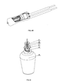
- Fig. 5 illustrates the structure of third embodiment applied in a fragrance device
- Fig.6 illustrates the structure of fourth embodiment of a resistor with an organism temperature sensing built-in thermal fuse
- Fig.7 illustrates the principle diagram of the fourth embodiment of a resistor with an organism temperature sensing built-in thermal fuse.
- the first embodiment will be further described with the fig.1, fig.2A and fig.3A . thereinto, the object of the embodiment is to describe the preferred embodiment of the present invention, but not limited.
- Fig.1 is the circuit of a switched power supply charger of a mobilephone or an MP3, and the circuit is applied with the device combining a thermal fuse and a resistor of the present invention; in fig.2A , the lead wires 2b, 2a of the thermal fuse is welded with low-melting point alloy wire 3.
- a fluxing agent 4 is disposed around the alloy wire 3 to improve the alloy wire to contract to two sides and cut off when molten, the thermal fuse, fluxing agent 4 and the alloy wire 3 form a whole under the normal temperature to be placed inside the ceramic tube, then two ends of the ceramic tube are encapsulated by epoxy resin 6 to be made into an entire thermal fuse.
- the hole in the centre of the metal cap 5a is large enough for the lead wire 2a of the thermal fuse to pass through, a clearance is formed between the hole and the lead wire 2a, the creepage distance of the lead wire 2a and the metal cap 5a increases to a safe distance after the clearance is encapsulated by epoxy resin 6.
- Fig.4 and fig.5 are the actual assemblies of the present invention.
- fig.4B is circuit structure that the thermal fuse and the wirewound resistor are connected in series with one end input and the other end output.
- Fig.1 is the circuit of the present invention applied in a high-frequency charger, in which the wirewound resistor is in over-heat protection mode.
- the thermal fuse and the wirewound resistor are connected in parallel in a circuit, the wirewound resistor is wound to the ceramic housing of the thermal fuse.
- the lead wires of the metal caps (5a, 5c) in two ends of the wirewound resistor are not connected to the lead wires of the thermal fuse.
- the table below is the protection result data of the wirewound resistor with a thermal fuse in the first embodiment.
- a high-frequency power supply it often applies a 10 ⁇ /2W wirewound resistor and a 221°C thermal fuse against over-heat, the comparison of cut-off speed of the external contact type and the built-in type (the first embodiment) is as below. If single wirewound resistor is not added, high surface temperature for a long time is a hidden danger in the current in the table.
- the structure of the fourth embodiment is the same as that of the first embodiment, with different resistor value and temperature from the first embodiment, the heating of the wirewound resistor accelerates the cut-off of the thermal fuse, it is mainly applied in the motor against over-heat.
- the resistor value of the wirewound resistor with above structure is set in 0.5 ⁇
- the temperature of the coupling thermal fuse is 150°C used in a motor of a power tool
- the structure of the fifth embodiment is the same as that of the first embodiment, as figured in fig.4B , replace the wirewound resistor to a carbon-film resistor or a metal-film resistor 22, the resistor value is increased to thousands of ohms, this structure can be used as a micro-heater 21 (as figured in fig.5 ); the micro-heater 21 of built-in thermal fuse is made into a fragrance device, which comprising a micro-heater 21, a housing 23, a diffusion staff 24, a sealing ring 25, a perfume bottle 26. put the housing 23 with a built-in micro-heater 21 into the diffusion staff 24, the diffusion staff 24 is passed through the sealing ring 25 and inserted into the perfume bottle 26, forming a fragrance device.
- the power consumption of this embodiment is a saving of 50% power to existing technology.
- an organism temperature sensing thermal fuse 30 is disposed inside the ceramic tube 1 (the principle structure is figured in fig.7 ), two ends of the ceramic tube 1 are locked with the metal caps 5a, 5b, forming a tight integration.
- the centre of the metal cap 5b is extended out with a liplike edge, which is connected to the lead wire 2b of the thermal fuse 30; when the metal cap 5b is welded with the alloy wire of the wirewound resistor, the thermal fuse and the wirewound resistor are connected in series.
- the hole in the centre of the metal cap 5a is large enough for the lead wire 2a of the thermal fuse 30 to pass through, a clearance is formed between the hole and the lead wire 2a, the creepage distance of the lead wire 2a and the metal cap 5a increases to a safe distance after the clearance is encapsulated by epoxy resin 6.
- a clearance is formed between the hole and the lead wire 2b, the creepage distance of the lead wire 2b and the metal cap 5b increases to a safe distance after the clearance is encapsulated by epoxy resin 6.
- the resistor and the thermal fuse have no electrical connections but quick thermal transferring.
- the present invention can be served as a basic unit, which is directly assembled to an existing high-frequency charger, it can take place of the existing simple wirewound resistor or the wirewound resistor with a thermal fuse external contacted, realizing triple functions of normal resistor function, melt protection function in high current, over-heat protection when overloaded.
Abstract
Description
- The present invention relates to a resistor against over-current and over-heat, the device is a quick response structure with a resistor and a thermal fuse integration, the size is similar to a same power wirewound resistor, carbon-film resistor or a metal-film resistor, it's applied to over-heat resistor of the power supply of the household electric appliance, IT communication equipment or lighting equipment, it can be also be served as a heating element with over-heat protection.
- The present invention further relates to a thermal fuse with heating function, it can be applied in blockage protection of the motor of the power tool or electrical fan; when the motor is blocked, with the current, the increasing rate of the temperature of the thermal fuse to cut off is much larger than that of the temperature of the coil of the motor, assuring that the motor will not be over-heat and blocked before the cut-off of the thermal fuse, it can be used to against over-heat of the motor.
- With the widely application of the inicroelectrical equipment, especially the mobile communication equipment, charging device of a battery is the necessity of the mobile equipment. A high-frequency circuit is usually applied to design and construct a charger. For convenient to carry and the self-adaptation the AC100V~240V mains voltage, the safety performance of the charger is important. A current-limiting resistor against over-current and over-heat is the key component to the safety of the high-frequency circuit. The present invention is provided to meet the demanding with the safety performance of reliability and quick response.
- Although the wirewound resistor also has over-current melt function, the resistor wire is applied with high melting point alloy and the alloy wire of the wirewound resistor will be melt to realize fuse function only if over 20 times of rated current flows. However, in actual application, when the load is abnormal, the current of the wirewound resistor is often unable to reach to the melt current, the melt performance of the wirewound resistor can not be present, the temperature of the wirewound resistor reaches to 300~500°C, being a seriously danger to the charger. So that people applies with a thermal fuse external contacted in series and placed inside a ceramic box, when the thermal fuse senses that the temperature of the wirewound resistor reaches to the rating temperature of the thermal fuse, the thermal fuse is melt to cut off the circuit. However, it occupies two areas in the PCB and it needs 4 bonding pads.
- In another hand, according to safety consideration, the micro-heating elements, such as fragrance device or liquid electric mat, are applied with a thermal fuse against over-heat. Existing assembly method is to connect a resistor and a thermal fuse in series then assemble above both inside a ceramic box, the box is filled with solidifiable insulation material. But the size of the product is too large, heat may lose too much, making energy waste.
- In addition, the current of the blocked motor of power tool or electrical fan is six times of normal working current, the motor is heating fast, so it needs a thermal fuse to cut off the current to prevent over-heat and fire, but not to decrease the operation temperature of the thermal fuse to increase the agility. However, mild overload or voltage pulsation happens when the motor works, but the thermal fuse is unexpected to cut off. So trouble happens when setting the temperature of the thermal fuse.
- An integration combining a thermal fuse and a resistor of new, small size, integrative structural and fast installation is provided, this structure may solve above three problems.
- The present invention is provided with a resistor applied to the input of a high-frequency charger, and it adopts an alloy wire as the resistor, which has the resistor function and the melt protection function in high current. A thermal fuse is disposed inside the base of the wirewound resistor; the thermal fuse is connected to the resistor in series in the circuit. When the wirewound resistor heats to the rated temperature, the thermal fuse is melt to assure over-heat protection function.
- The present invention relates to a wirewound resistor with a thermal fuse built-in, in which the solid ceramic base of the wirewound resistor is changed to be hollow, a thermal fuse is disposed inside the ceramic base, the ceramic tube is severed as the housing of the thermal fuse, when one lead wire of the thermal fuse is passing through the end cap of one end of the wirewound resistor, the thermal fuse and the wirewound resistor are connected in serious tightly, and the other lead wire of the thermal fuse is extended out of the end cap of the other end of the wirewound resistor, the end cap of the wirewound resistor with an opening is extended out with a lead wire, then the whole product is encapsulated by epoxy resin.
- The present invention of a wirewound resistor with a built-in thermal fuse can be severed as a basic unit to be assembled directly to the existing high-frequency charger, the wirewound resistor with a built-in thermal fuse can take the place of the existing simple wirewound resistor or the wirewound resistor with a thermal fuse external contacted, realizing triple functions of normal resistor function, melt protection function in high current, over-heat protection when overloaded.
- The resistor value of the wirewound resistor with above structure is set in 0.5 Ω, the temperature of the coupling thermal fuse is 150°C used in a motor of a power tool, take a thermal fuse with rated current 2A for example, when the normal working current is 0.5A, the temperature of the thermal fuse rises about 5°C due to the resistor. But when the motor is blocked, the current reaches to 3A, the heat of the resistor makes the temperature of the thermal fuse rising rapidly, the thermal fuse is cut off before the motor coil is damaged.
- According to above structure, replace the wirewound resistor to a carbon-film resistor or a metal-film resistor, the resistor value is increased greatly, this structure can be used as a micro-heater, fix it into a ceramic tube to sever as a heater of a fragrance device or liquid electric mat, the heater can be placed in the diffusion staff of perfume or other liquid, so that the thermal power of the heater can be absorbed by the perfume or other liquid. Existing technology is applied with a ceramic structure, one side of which is disposed with a hole to fix the diffusion staff while the other side is disposed with a cavity, the cavity is assembled with a heating resistor and a thermal fuse and encapsulated by solidifiable insulation material. Comparing above two, basic on same diffusion rate of the perfume, the power of the existing technology of the heater is about 2.2W, the power of the heater of the present invention is about 1W, so that the heating temperature of the resistor is decreased, the stability of the resistor value of the resistor is improved greatly and the diffusion rate of the perfume is more stable, the influence from the environmental temperature is decreased. If the power of a fragrance device decreases 1W, 9kW power can be saved every year. If there are 50 millions heaters of fragrance device or liquid electric mat working in the world, 45000kW power can be saved, carbon emission decreased greatly.
-
Fig.1 illustrates the circuit diagram of the first embodiment; -
Fig.2A illustrates the structure of the thermal fuse of the first embodiment; -
Fig.2B illustrates the structure of the thermal fuse of the second embodiment; -
Fig.3A illustrates the structure of the wirewound resistor of the first embodiment; -
Fig.3B illustrates the structure of the wirewound resistor of the second embodiment; -
Fig.4A illustrates the structure of the structure of the application product of the first embodiment; -
Fig.4B illustrates the structure of the structure of the first embodiment without the lead wire in the common port of the wirewound resistor and the thermal fuse; -
Fig. 5 illustrates the structure of third embodiment applied in a fragrance device; -
Fig.6 illustrates the structure of fourth embodiment of a resistor with an organism temperature sensing built-in thermal fuse; -
Fig.7 illustrates the principle diagram of the fourth embodiment of a resistor with an organism temperature sensing built-in thermal fuse. - The first embodiment:
- The first embodiment will be further described with the
fig.1, fig.2A andfig.3A . thereinto, the object of the embodiment is to describe the preferred embodiment of the present invention, but not limited. -
Fig.1 is the circuit of a switched power supply charger of a mobilephone or an MP3, and the circuit is applied with the device combining a thermal fuse and a resistor of the present invention; infig.2A , thelead wires point alloy wire 3. Afluxing agent 4 is disposed around thealloy wire 3 to improve the alloy wire to contract to two sides and cut off when molten, the thermal fuse,fluxing agent 4 and thealloy wire 3 form a whole under the normal temperature to be placed inside the ceramic tube, then two ends of the ceramic tube are encapsulated byepoxy resin 6 to be made into an entire thermal fuse. - As figured in
fig.2A , when above thermal fuse is formed, put themetal caps ceramic tube 1 of the thermal fuse, forming a tight integration. The centre of themetal cap 5b is extended out with a liplike edge, which is connected to thelead wire 2b of the thermal fuse; when themetal cap 5b is welded to the alloy wire of the wirewound resistor, the thermal fuse and the wirewound resistor are connected in series. The hole in the centre of themetal cap 5a is large enough for thelead wire 2a of the thermal fuse to pass through, a clearance is formed between the hole and thelead wire 2a, the creepage distance of thelead wire 2a and themetal cap 5a increases to a safe distance after the clearance is encapsulated byepoxy resin 6. - When two ends of the
ceramic tube 1 of the thermal fuse are sleeved with themetal cap resistor alloy wire 7 in the basic body, two ends of theresistor alloy wire 7 are welded to themetal cap lead wire 8 is welded to themetal cap 5a as the output of the wirewound resistor. The whole product is encapsulated by epoxyresin 9 finally. In this way, a wirewound resistor with a built-in thermal fuse is made, as figured infig.3A . -
Fig.4 andfig.5 are the actual assemblies of the present invention.fig.4B is circuit structure that the thermal fuse and the wirewound resistor are connected in series with one end input and the other end output.Fig.1 is the circuit of the present invention applied in a high-frequency charger, in which the wirewound resistor is in over-heat protection mode. - The second embodiment:
- As figured in
fig.2B and fig.3B , different from the first embodiment, the thermal fuse and the wirewound resistor are connected in parallel in a circuit, the wirewound resistor is wound to the ceramic housing of the thermal fuse. The lead wires of the metal caps (5a, 5c) in two ends of the wirewound resistor are not connected to the lead wires of the thermal fuse. - The third embodiment:
- The table below is the protection result data of the wirewound resistor with a thermal fuse in the first embodiment. In a high-frequency power supply, it often applies a 10Ω/2W wirewound resistor and a 221°C thermal fuse against over-heat, the comparison of cut-off speed of the external contact type and the built-in type (the first embodiment) is as below. If single wirewound resistor is not added, high surface temperature for a long time is a hidden danger in the current in the table.
-
[Table 1] Number Test Current A Surface Temperature of the External Contact Type Resistor °C Cut-off Time of the External Contact Type Thermal Fuse S Surface Temperature of the Built-in Type Resistor °C Cut-off Time of the Built-in Type Thermal Fuse S 1 0.5 142 Not Cut-off in 600s 145 Not Cut-off in 600s 2 0.5 139 Not Cut-off in 601s 142 Not Cut-off in 601s 3 0.5 146 Not Cut-off in 602s 148 Not Cut-off in 602s 4 0.5 143 Not Cut-off in 603s 145 Not Cut-off in 603s 5 0.6 175 36s 176 18s 6 0.6 174 37s 177 19s 7 0.6 178 36s 176 18s 8 0.6 176 39s 178 18s 9 0.7 189 26s 190 8s 10 0.7 187 27s 192 7s 11 0.7 190 23s 193 8s 12 0.7 188 24s 189 7s 13 0.8 211 14s 215 1.2s 14 0.8 209 16s 212 1.0s 15 1 234 8s 238 0.2s 16 1 232 9s 242 0.2s - The fourth embodiment:
- The structure of the fourth embodiment is the same as that of the first embodiment, with different resistor value and temperature from the first embodiment, the heating of the wirewound resistor accelerates the cut-off of the thermal fuse, it is mainly applied in the motor against over-heat. The resistor value of the wirewound resistor with above structure is set in 0.5Ω, the temperature of the coupling thermal fuse is 150°C used in a motor of a power tool, take a thermal fuse with rated current 2A for example, when the normal working current is 0.5A, the temperature of the thermal fuse rises about 5°C due to the resistor. But when the motor is blocked, the current reaches to 3A, the heat of the resistor makes the temperature of the thermal fuse rising rapidly, the thermal fuse is cut off before the motor coil is damaged, pretending the motor coil form burning and improving the recycle value. It can be further described with the data below:
[Table 2] Number Fusing Current A Temperature of the Simulation Coil °C Surface Temperature of the Wirewound Resistor °C Cut-off Time of the TCO Withstand Voltage 1 0.5 62.8 74.9 Not Cut-off in a Long Time 2 0.5 63.1 75.4 Not Cut-off in a Long Time 3 0.5 62.9 75.8 Not Cut-off in a Long Time 4 1 63.6 90.2 Not Cut-off in a Long Time 5 1 63.8 90.8 Not Cut-off in a Long Time 6 1 63.9 91.4 Not Cut-off in a Long Time 7 1.5 64.5 107.4 Not Cut-off in a Long Time Not Breakdown in 500V 8 1.5 64.6 106.9 Not Cut-off in a Long Time Not Breakdown in 500V 9 1.5 64.7 107.8 Not Cut-off in a Long Time Not Breakdown in 500V 10 2 65.4 132.5 58 Not Breakdown in 500V 11 2 65.5 132.1 52 Not Breakdown in 500V 12 2.5 66.7 162.7 7 Not Breakdown in 500V 13 2.5 66.4 160.2 6 Not Breakdown in 500V 14 3 69.4 167.5 3 Not Breakdown in 500V - The fifth embodiment:
- The structure of the fifth embodiment is the same as that of the first embodiment, as figured in
fig.4B , replace the wirewound resistor to a carbon-film resistor or a metal-film resistor 22, the resistor value is increased to thousands of ohms, this structure can be used as a micro-heater 21 (as figured infig.5 ); themicro-heater 21 of built-in thermal fuse is made into a fragrance device, which comprising a micro-heater 21, ahousing 23, adiffusion staff 24, a sealingring 25, aperfume bottle 26. put thehousing 23 with a built-in micro-heater 21 into thediffusion staff 24, thediffusion staff 24 is passed through the sealingring 25 and inserted into theperfume bottle 26, forming a fragrance device. -
[Table 3] Test Report of the Comparison of the Heating of the Resistor Assembly Type of the Heating Resistor Test Voltage Current Real Power Resistor Value Ω Surface Temperature °C Temperature of the Diffusion Staff °C a Resistor with a 130°C External Contact Thermal Fuse is Encapsulated by a Ceramic Housing 120VAC 18.52mA 2.2W 6.5K 97.5 89.6 a Resistor with a 130°C External Contact Thermal Fuse is Encapsulated by a Ceramic Housing 120VAC 18.51mA 2.2W 6.5K 94.3 88.2 a Resistor with a 130°C External Contact Thermal Fuse is Encapsulated by a Ceramic Housing 120VAC 18.55mA 2.2W 6.5K 95.6 87.9 a Resistor with a 130°C External Contact Thermal Fuse is Encapsulated by a Ceramic Housing 120VAC 18.52mA 2.2W 6.5K 96.8 86.5 a Resistor with a 130°C External Contact Thermal Fuse is Encapsulated by a Ceramic Housing 120VAC 18.53mA 2.2W 6.5K 95.8 87.9 a Resistor with a Built-in Thermal Fuse 120VAC 10.4mA 1.25W 11.5K 92 92 a Resistor with a Built-in Thermal Fuse 120VAC 10.4mA 1.25W 11.5K 90.8 90.8 a Resistor with a Built-in Thermal Fuse 120VAC 10.4mA 1.25W 11.5K 93.2 93.2 a Resistor with a Built-in Thermal Fuse 120VAC 10.4mA 1.25W 11.5K 92.7 92.7 a Resistor with a Built-in Thermal Fuse 120VAC 10.4mA 1.25W 11.5K 91.8 91.8 - According to above data comparison, under equal temperature of the diffusion staff, the power consumption of this embodiment is a saving of 50% power to existing technology.
- The sixth embodiment:
- As figured in
fig.6 , an organism temperature sensingthermal fuse 30 is disposed inside the ceramic tube 1 (the principle structure is figured infig.7 ), two ends of theceramic tube 1 are locked with themetal caps metal cap 5b is extended out with a liplike edge, which is connected to thelead wire 2b of thethermal fuse 30; when themetal cap 5b is welded with the alloy wire of the wirewound resistor, the thermal fuse and the wirewound resistor are connected in series. The hole in the centre of themetal cap 5a is large enough for thelead wire 2a of thethermal fuse 30 to pass through, a clearance is formed between the hole and thelead wire 2a, the creepage distance of thelead wire 2a and themetal cap 5a increases to a safe distance after the clearance is encapsulated byepoxy resin 6. if the shape of themetal cap 5b is like themetal cap 5a, and thelead wire 2b of thethermal fuse 30 is passing through the centre, a clearance is formed between the hole and thelead wire 2b, the creepage distance of thelead wire 2b and themetal cap 5b increases to a safe distance after the clearance is encapsulated byepoxy resin 6. the resistor and the thermal fuse have no electrical connections but quick thermal transferring. - When two ends of the
ceramic tube 1 of the thermal fuse are sleeved with themetal cap resistor alloy wire 7 in the basic body, two ends of theresistor alloy wire 7 are welded to themetal cap lead wire 8 is welded to themetal cap 5a as the output of the wirewound resistor. The whole product is encapsulated byepoxy resin 9 finally. In this way, a wirewound resistor with a built-in thermal fuse is made out. The wirewound resistor on the external surface of theceramic tube 1 can be changed into a carbon-film resistor, a metal-film resistor or a thick film resistor, forming a resistor against over-heat with different power. - The present invention can be served as a basic unit, which is directly assembled to an existing high-frequency charger, it can take place of the existing simple wirewound resistor or the wirewound resistor with a thermal fuse external contacted, realizing triple functions of normal resistor function, melt protection function in high current, over-heat protection when overloaded.
Claims (9)
- A device combining a thermal fuse and a resistor, wherein the solid ceramic base of the wirewound resistor is changed to be hollow, a thermal fuse is disposed inside the ceramic base, the ceramic tube is the housing of the thermal fuse, one lead wire of the thermal fuse is passing through the end cap of one end of the wirewound resistor, the other end of the thermal fuse is extended out of the end cap of the other end of the wirewound resistor, the end cap of the wirewound resistor is extended out with a lead wire, then the whole product is encapsulated by epoxy resin.
- A device combining a thermal fuse and a resistor according to claim 1, wherein the lead wire of the thermal fuse is passing through the end cap of one end of the wirewound resistor, making the thermal fuse is connected to the wirewound resistor in series.
- A device combining a thermal fuse and a resistor according to claim 2, wherein a fluxing agent is disposed around the low melting alloy wire between two lead wires of the thermal fuse to improve the alloy wire to contract to two sides and cut off when molten, the thermal fuse, fluxing agent and the alloy wire form a whole under the normal temperature and place inside the ceramic tube.
- A device combining a thermal fuse and a resistor according to claim 2, wherein the wirewound resistor with a built-in thermal fuse can be serviced as a basic unit to assemble to a high-frequency charger.
- A device combining a thermal fuse and a resistor according to claim 2, wherein the resistor value of the wirewound resistor and the temperature value of the thermal fuse are collected to accompany with each other, making that the wirewound resistor heated to accelerate the thermal fuse to cut off, the device combining a thermal fuse and a resistor is applied in a motor with over-heat protection.
- A device combining a thermal fuse and a resistor according to claim 2, wherein the alloy wire resistor is carbon-film resistor or metal-film resistor, the resistor value increase to thousands of ohms, forming a heating resistor with over-heat protection.
- A device combining a thermal fuse and a resistor according to claim 1, wherein the end caps in two ends of the resistor are opened, two lead wires of the thermal fuse are passing through the openings of the end caps, two end caps of the resistor are separately disposed with a lead wire extended out and then encapsulated by epoxy resin, forming a circuit that the thermal fuse and the resistor are parallel to each other and realizing to cut off the thermal fuse heater by different circuits.
- A device combining a thermal fuse and a resistor according to claim 1, wherein the product is encapsulated by epoxy resin and insulated or applied with silicone or inorganic material as insulation layer.
- A device combining a thermal fuse and a resistor according to claim 1, wherein two ends of the ceramic base of the resistor are opened, or one end of the ceramic base of the resistor is opened while the other end is disposed with a hole for a lead pin to extend out.
Applications Claiming Priority (2)
| Application Number | Priority Date | Filing Date | Title |
|---|---|---|---|
| CN2010206974387U CN202632917U (en) | 2010-12-31 | 2010-12-31 | Device combining temperature fuse and resistor |
| PCT/CN2011/084826 WO2012089124A1 (en) | 2010-12-31 | 2011-12-28 | Apparatus comprising thermal fuse and resistor |
Publications (3)
| Publication Number | Publication Date |
|---|---|
| EP2660828A1 true EP2660828A1 (en) | 2013-11-06 |
| EP2660828A4 EP2660828A4 (en) | 2017-01-18 |
| EP2660828B1 EP2660828B1 (en) | 2017-12-20 |
Family
ID=46382317
Family Applications (1)
| Application Number | Title | Priority Date | Filing Date |
|---|---|---|---|
| EP11853301.7A Not-in-force EP2660828B1 (en) | 2010-12-31 | 2011-12-28 | Apparatus comprising thermal fuse and resistor |
Country Status (6)
| Country | Link |
|---|---|
| US (1) | US9240300B2 (en) |
| EP (1) | EP2660828B1 (en) |
| JP (1) | JP2014501435A (en) |
| KR (1) | KR20140040081A (en) |
| CN (1) | CN202632917U (en) |
| WO (1) | WO2012089124A1 (en) |
Cited By (3)
| Publication number | Priority date | Publication date | Assignee | Title |
|---|---|---|---|---|
| EP3096332A4 (en) * | 2014-01-17 | 2017-09-13 | First Resistor Condenser Co., Ltd. | Surge-resistant wire-wound resistor and method for manufacturing same |
| EP4089711A4 (en) * | 2020-01-15 | 2023-07-19 | BYD Company Limited | Multifunctional fuse |
| EP4339985A1 (en) * | 2022-09-16 | 2024-03-20 | Therm-O-Disc, Incorporated | Thermal cut-off device for high power applications |
Families Citing this family (15)
| Publication number | Priority date | Publication date | Assignee | Title |
|---|---|---|---|---|
| CN202632917U (en) * | 2010-12-31 | 2012-12-26 | 厦门赛尔特电子有限公司 | Device combining temperature fuse and resistor |
| CN102610340A (en) * | 2012-04-05 | 2012-07-25 | 安徽昌盛电子有限公司 | Temperature insured anti-lightning surge wirewound resistor |
| KR101389709B1 (en) * | 2012-11-15 | 2014-04-28 | (주)엠에스테크비젼 | Repeatable fuse for preventing over-current and absorbing surge |
| US10874141B2 (en) * | 2013-08-20 | 2020-12-29 | VMR Products, LLC | Vaporizer |
| US10170266B2 (en) * | 2014-01-17 | 2019-01-01 | First Resistor & Condenser Co., Ltd. | Wire-wound fuse resistor and method for manufacturing same |
| KR101614123B1 (en) * | 2014-08-19 | 2016-04-20 | 김용운 | Fuse intergrated resistor |
| CN204926939U (en) * | 2015-09-06 | 2015-12-30 | 东莞市贝特电子科技股份有限公司 | Two unification resistance |
| US20170098522A1 (en) * | 2015-10-06 | 2017-04-06 | Ty-Ohm Electronic Works Co., Ltd. | Temperature safety resistor assembly |
| CN105321636A (en) * | 2015-12-07 | 2016-02-10 | 安徽昌盛电子股份有限公司 | Axial lead type temperature insurance resistor |
| US9984797B2 (en) * | 2016-05-13 | 2018-05-29 | Elmatek Internation Corp. | High voltage (HV) impedance device with surface leakage proof configuration applied in HV divider |
| CN108039255A (en) * | 2017-12-22 | 2018-05-15 | 南京萨特科技发展有限公司 | A kind of fuse-resistor and preparation method thereof |
| US10347402B1 (en) * | 2018-05-23 | 2019-07-09 | Xiamen Set Electronics Co., Ltd. | Thermal fuse resistor |
| CN109859915A (en) * | 2019-04-02 | 2019-06-07 | 安徽省昌盛电子有限公司 | The explosion-proof wirewound resistor of high anti-lightning low current fusing |
| CN111816396A (en) * | 2020-06-12 | 2020-10-23 | 安徽昭田电子科技有限公司 | Low-temperature coefficient metal film resistor and manufacturing process thereof |
| CN113690965A (en) * | 2021-07-09 | 2021-11-23 | 东莞新能安科技有限公司 | Protection circuit and circuit board, battery management system and battery package |
Family Cites Families (29)
| Publication number | Priority date | Publication date | Assignee | Title |
|---|---|---|---|---|
| GB948070A (en) * | 1960-04-07 | 1964-01-29 | Ass Elect Ind | Improvements relating to the formation of conductive surfaces |
| US3836883A (en) * | 1971-12-08 | 1974-09-17 | Hokuriku Elect Ind | Fuse and resistor device |
| US3735312A (en) * | 1971-12-30 | 1973-05-22 | Bell Telephone Labor Inc | Three terminal fuse-resistor device |
| ZA72375B (en) * | 1972-01-19 | 1973-06-27 | Exec Ltd | Sequential activation of electrical apparatus |
| US4006443A (en) * | 1975-09-11 | 1977-02-01 | Allen-Bradley Company | Composition resistor with an integral thermal fuse |
| DE2700975A1 (en) * | 1977-01-12 | 1978-07-13 | Draloric Electronic | Wire wound resistor on fibrous cylindrical former - has axial hole to return resistance wire to starting end |
| DE8322638U1 (en) * | 1983-08-05 | 1984-01-05 | Thienel, Bernhard, 5900 Siegen | Fuse cartridge |
| JPS6059692B2 (en) * | 1984-06-14 | 1985-12-26 | 内橋金属工業株式会社 | temperature fuse resistor |
| JPS6117703U (en) * | 1984-07-06 | 1986-02-01 | 株式会社 日本抵抗器製作所 | Temperature compensation resistor |
| US4593262A (en) * | 1985-03-22 | 1986-06-03 | Littelfuse, Inc. | Time delay indicator fuse |
| JPS6445102A (en) * | 1987-08-13 | 1989-02-17 | Matsushita Electric Works Ltd | Safety device for blower |
| JPH01133705U (en) * | 1988-03-07 | 1989-09-12 | ||
| JP2559875B2 (en) * | 1990-03-16 | 1996-12-04 | 日本碍子株式会社 | Resistor element |
| US5418516A (en) * | 1993-11-09 | 1995-05-23 | Littlefuse, Inc. | Surge resistor fuse |
| JP3696635B2 (en) * | 1994-08-31 | 2005-09-21 | 内橋エステック株式会社 | How the temperature protector works |
| JPH08250301A (en) | 1995-03-15 | 1996-09-27 | Kyosan Electric Mfg Co Ltd | Insulated wire wound power resistor |
| CN2233617Y (en) | 1995-11-14 | 1996-08-21 | 刘少锋 | High-temp, high-voltage and high-power wire-wound resistor |
| JP3248851B2 (en) * | 1996-10-29 | 2002-01-21 | エヌイーシーモバイルエナジー株式会社 | Battery protection device |
| JPH10255622A (en) * | 1997-03-07 | 1998-09-25 | Jimu Denki Kk | Resistant thermal fuse |
| US7221253B2 (en) * | 2002-07-09 | 2007-05-22 | Smart Electronics Inc. | Fusible resistor and method of fabricating the same |
| JP4064217B2 (en) * | 2002-11-26 | 2008-03-19 | 内橋エステック株式会社 | Alloy type thermal fuse and material for thermal fuse element |
| JP2004241665A (en) * | 2003-02-07 | 2004-08-26 | Micron Electric Co Ltd | Cement resistor |
| JP2005171371A (en) * | 2003-12-15 | 2005-06-30 | Uchihashi Estec Co Ltd | Alloy type thermal fuse and wire material for thermal fuse element |
| JP2008097943A (en) * | 2006-10-11 | 2008-04-24 | Uchihashi Estec Co Ltd | Temperature fuse built-in resistor |
| CN101859665A (en) | 2009-04-07 | 2010-10-13 | 厦门赛尔特电子有限公司 | Alloy type thermal fuse with high ampere capacity |
| KR101038237B1 (en) * | 2009-04-21 | 2011-05-31 | 스마트전자 주식회사 | Thermal Fuse Resistor |
| CN201655721U (en) | 2010-01-06 | 2010-11-24 | 王江喜 | High-voltage protective tube component for ozone generator |
| CN102714079B (en) * | 2010-01-29 | 2016-11-02 | 弗莱克斯电子有限责任公司 | There is the resistor of thermal element |
| CN202632917U (en) * | 2010-12-31 | 2012-12-26 | 厦门赛尔特电子有限公司 | Device combining temperature fuse and resistor |
-
2010
- 2010-12-31 CN CN2010206974387U patent/CN202632917U/en not_active Expired - Lifetime
-
2011
- 2011-12-28 WO PCT/CN2011/084826 patent/WO2012089124A1/en active Application Filing
- 2011-12-28 EP EP11853301.7A patent/EP2660828B1/en not_active Not-in-force
- 2011-12-28 KR KR1020137018197A patent/KR20140040081A/en not_active Application Discontinuation
- 2011-12-28 JP JP2013546579A patent/JP2014501435A/en active Pending
- 2011-12-28 US US13/977,672 patent/US9240300B2/en active Active
Non-Patent Citations (1)
| Title |
|---|
| See references of WO2012089124A1 * |
Cited By (4)
| Publication number | Priority date | Publication date | Assignee | Title |
|---|---|---|---|---|
| EP3096332A4 (en) * | 2014-01-17 | 2017-09-13 | First Resistor Condenser Co., Ltd. | Surge-resistant wire-wound resistor and method for manufacturing same |
| EP4089711A4 (en) * | 2020-01-15 | 2023-07-19 | BYD Company Limited | Multifunctional fuse |
| US11798768B2 (en) | 2020-01-15 | 2023-10-24 | Byd Company Limited | Fusing device |
| EP4339985A1 (en) * | 2022-09-16 | 2024-03-20 | Therm-O-Disc, Incorporated | Thermal cut-off device for high power applications |
Also Published As
| Publication number | Publication date |
|---|---|
| CN202632917U (en) | 2012-12-26 |
| US9240300B2 (en) | 2016-01-19 |
| EP2660828A4 (en) | 2017-01-18 |
| EP2660828B1 (en) | 2017-12-20 |
| US20130293343A1 (en) | 2013-11-07 |
| KR20140040081A (en) | 2014-04-02 |
| WO2012089124A1 (en) | 2012-07-05 |
| JP2014501435A (en) | 2014-01-20 |
Similar Documents
| Publication | Publication Date | Title |
|---|---|---|
| EP2660828A1 (en) | Apparatus comprising thermal fuse and resistor | |
| US9530545B2 (en) | Device comprising a thermal fuse and a resistor | |
| CN203933002U (en) | A kind of surge absoption protector with the hot detaching structure of displacement interrupter-type | |
| CN205335209U (en) | Multifunctional protection device and electronic device | |
| CN203300549U (en) | Temperature fuse protector with dual-protection function | |
| CN104835702A (en) | Composite protection element | |
| CN208173323U (en) | Thermal protection type varistor | |
| CN202602242U (en) | Self-recovery over-current and over-temperature protective device | |
| CN209625950U (en) | Overheat overvoltage protection piezoresistor | |
| CN101042952B (en) | Varistor with novel short-circuit protection device | |
| CN206163219U (en) | Novel hot protection type resistor | |
| CN204834219U (en) | Thermistor with fuse | |
| CN105493219A (en) | Shutoff element and shutoff element circuit | |
| CN110729578A (en) | Binding post structure and electric appliance comprising same | |
| CN201570468U (en) | Resistive fuse device | |
| CN211320041U (en) | Fuse based on intelligent PTC high polymer material | |
| CN108695127A (en) | Protection element and battery pack thereof | |
| CN209045264U (en) | A kind of Thermal protection type varistor | |
| CN210245194U (en) | Piezoresistor with protection component | |
| CN208908204U (en) | A kind of overheat overcurrent power-off protection device | |
| CN102412094B (en) | Protective circuit | |
| CN209344015U (en) | A kind of series combination type overflow protecting element | |
| CN206301650U (en) | A kind of piezoresistor of built-in temperature fuse-link | |
| CN208240427U (en) | A kind of small-size multifunction shape temperature resistance | |
| JP3204027U (en) | Overheat overcurrent protection device |
Legal Events
| Date | Code | Title | Description |
|---|---|---|---|
| PUAI | Public reference made under article 153(3) epc to a published international application that has entered the european phase |
Free format text: ORIGINAL CODE: 0009012 |
|
| 17P | Request for examination filed |
Effective date: 20130731 |
|
| AK | Designated contracting states |
Kind code of ref document: A1 Designated state(s): AL AT BE BG CH CY CZ DE DK EE ES FI FR GB GR HR HU IE IS IT LI LT LU LV MC MK MT NL NO PL PT RO RS SE SI SK SM TR |
|
| DAX | Request for extension of the european patent (deleted) | ||
| RA4 | Supplementary search report drawn up and despatched (corrected) |
Effective date: 20161221 |
|
| RIC1 | Information provided on ipc code assigned before grant |
Ipc: H01H 37/76 20060101ALI20161215BHEP Ipc: H01C 3/20 20060101AFI20161215BHEP Ipc: H01H 85/02 20060101ALN20161215BHEP Ipc: H01C 1/08 20060101ALI20161215BHEP Ipc: H05B 1/02 20060101ALI20161215BHEP Ipc: H01C 1/14 20060101ALI20161215BHEP Ipc: H01H 85/00 20060101ALI20161215BHEP Ipc: H01H 85/165 20060101ALN20161215BHEP |
|
| GRAP | Despatch of communication of intention to grant a patent |
Free format text: ORIGINAL CODE: EPIDOSNIGR1 |
|
| RIC1 | Information provided on ipc code assigned before grant |
Ipc: H01H 85/00 20060101ALI20170830BHEP Ipc: H01H 37/76 20060101ALI20170830BHEP Ipc: H01C 1/08 20060101ALI20170830BHEP Ipc: H01H 85/02 20060101ALN20170830BHEP Ipc: H01H 85/165 20060101ALN20170830BHEP Ipc: H01C 3/20 20060101AFI20170830BHEP Ipc: H05B 1/02 20060101ALI20170830BHEP Ipc: H01C 1/14 20060101ALI20170830BHEP |
|
| INTG | Intention to grant announced |
Effective date: 20171002 |
|
| GRAS | Grant fee paid |
Free format text: ORIGINAL CODE: EPIDOSNIGR3 |
|
| GRAA | (expected) grant |
Free format text: ORIGINAL CODE: 0009210 |
|
| AK | Designated contracting states |
Kind code of ref document: B1 Designated state(s): AL AT BE BG CH CY CZ DE DK EE ES FI FR GB GR HR HU IE IS IT LI LT LU LV MC MK MT NL NO PL PT RO RS SE SI SK SM TR |
|
| REG | Reference to a national code |
Ref country code: GB Ref legal event code: FG4D |
|
| REG | Reference to a national code |
Ref country code: CH Ref legal event code: EP |
|
| REG | Reference to a national code |
Ref country code: IE Ref legal event code: FG4D |
|
| REG | Reference to a national code |
Ref country code: AT Ref legal event code: REF Ref document number: 957057 Country of ref document: AT Kind code of ref document: T Effective date: 20180115 |
|
| REG | Reference to a national code |
Ref country code: DE Ref legal event code: R096 Ref document number: 602011044464 Country of ref document: DE |
|
| REG | Reference to a national code |
Ref country code: FR Ref legal event code: PLFP Year of fee payment: 7 |
|
| REG | Reference to a national code |
Ref country code: NL Ref legal event code: MP Effective date: 20171220 |
|
| PG25 | Lapsed in a contracting state [announced via postgrant information from national office to epo] |
Ref country code: SE Free format text: LAPSE BECAUSE OF FAILURE TO SUBMIT A TRANSLATION OF THE DESCRIPTION OR TO PAY THE FEE WITHIN THE PRESCRIBED TIME-LIMIT Effective date: 20171220 Ref country code: LT Free format text: LAPSE BECAUSE OF FAILURE TO SUBMIT A TRANSLATION OF THE DESCRIPTION OR TO PAY THE FEE WITHIN THE PRESCRIBED TIME-LIMIT Effective date: 20171220 Ref country code: FI Free format text: LAPSE BECAUSE OF FAILURE TO SUBMIT A TRANSLATION OF THE DESCRIPTION OR TO PAY THE FEE WITHIN THE PRESCRIBED TIME-LIMIT Effective date: 20171220 Ref country code: NO Free format text: LAPSE BECAUSE OF FAILURE TO SUBMIT A TRANSLATION OF THE DESCRIPTION OR TO PAY THE FEE WITHIN THE PRESCRIBED TIME-LIMIT Effective date: 20180320 |
|
| PGFP | Annual fee paid to national office [announced via postgrant information from national office to epo] |
Ref country code: DE Payment date: 20180215 Year of fee payment: 7 |
|
| REG | Reference to a national code |
Ref country code: LT Ref legal event code: MG4D |
|
| REG | Reference to a national code |
Ref country code: AT Ref legal event code: MK05 Ref document number: 957057 Country of ref document: AT Kind code of ref document: T Effective date: 20171220 |
|
| PG25 | Lapsed in a contracting state [announced via postgrant information from national office to epo] |
Ref country code: RS Free format text: LAPSE BECAUSE OF FAILURE TO SUBMIT A TRANSLATION OF THE DESCRIPTION OR TO PAY THE FEE WITHIN THE PRESCRIBED TIME-LIMIT Effective date: 20171220 Ref country code: BG Free format text: LAPSE BECAUSE OF FAILURE TO SUBMIT A TRANSLATION OF THE DESCRIPTION OR TO PAY THE FEE WITHIN THE PRESCRIBED TIME-LIMIT Effective date: 20180320 Ref country code: LV Free format text: LAPSE BECAUSE OF FAILURE TO SUBMIT A TRANSLATION OF THE DESCRIPTION OR TO PAY THE FEE WITHIN THE PRESCRIBED TIME-LIMIT Effective date: 20171220 Ref country code: HR Free format text: LAPSE BECAUSE OF FAILURE TO SUBMIT A TRANSLATION OF THE DESCRIPTION OR TO PAY THE FEE WITHIN THE PRESCRIBED TIME-LIMIT Effective date: 20171220 Ref country code: GR Free format text: LAPSE BECAUSE OF FAILURE TO SUBMIT A TRANSLATION OF THE DESCRIPTION OR TO PAY THE FEE WITHIN THE PRESCRIBED TIME-LIMIT Effective date: 20180321 |
|
| PGFP | Annual fee paid to national office [announced via postgrant information from national office to epo] |
Ref country code: FR Payment date: 20180130 Year of fee payment: 7 |
|
| PG25 | Lapsed in a contracting state [announced via postgrant information from national office to epo] |
Ref country code: NL Free format text: LAPSE BECAUSE OF FAILURE TO SUBMIT A TRANSLATION OF THE DESCRIPTION OR TO PAY THE FEE WITHIN THE PRESCRIBED TIME-LIMIT Effective date: 20171220 |
|
| PG25 | Lapsed in a contracting state [announced via postgrant information from national office to epo] |
Ref country code: SK Free format text: LAPSE BECAUSE OF FAILURE TO SUBMIT A TRANSLATION OF THE DESCRIPTION OR TO PAY THE FEE WITHIN THE PRESCRIBED TIME-LIMIT Effective date: 20171220 Ref country code: CZ Free format text: LAPSE BECAUSE OF FAILURE TO SUBMIT A TRANSLATION OF THE DESCRIPTION OR TO PAY THE FEE WITHIN THE PRESCRIBED TIME-LIMIT Effective date: 20171220 Ref country code: CY Free format text: LAPSE BECAUSE OF FAILURE TO SUBMIT A TRANSLATION OF THE DESCRIPTION OR TO PAY THE FEE WITHIN THE PRESCRIBED TIME-LIMIT Effective date: 20171220 Ref country code: EE Free format text: LAPSE BECAUSE OF FAILURE TO SUBMIT A TRANSLATION OF THE DESCRIPTION OR TO PAY THE FEE WITHIN THE PRESCRIBED TIME-LIMIT Effective date: 20171220 Ref country code: ES Free format text: LAPSE BECAUSE OF FAILURE TO SUBMIT A TRANSLATION OF THE DESCRIPTION OR TO PAY THE FEE WITHIN THE PRESCRIBED TIME-LIMIT Effective date: 20171220 |
|
| REG | Reference to a national code |
Ref country code: CH Ref legal event code: PL |
|
| PG25 | Lapsed in a contracting state [announced via postgrant information from national office to epo] |
Ref country code: SM Free format text: LAPSE BECAUSE OF FAILURE TO SUBMIT A TRANSLATION OF THE DESCRIPTION OR TO PAY THE FEE WITHIN THE PRESCRIBED TIME-LIMIT Effective date: 20171220 Ref country code: IS Free format text: LAPSE BECAUSE OF FAILURE TO SUBMIT A TRANSLATION OF THE DESCRIPTION OR TO PAY THE FEE WITHIN THE PRESCRIBED TIME-LIMIT Effective date: 20180420 Ref country code: RO Free format text: LAPSE BECAUSE OF FAILURE TO SUBMIT A TRANSLATION OF THE DESCRIPTION OR TO PAY THE FEE WITHIN THE PRESCRIBED TIME-LIMIT Effective date: 20171220 Ref country code: IT Free format text: LAPSE BECAUSE OF FAILURE TO SUBMIT A TRANSLATION OF THE DESCRIPTION OR TO PAY THE FEE WITHIN THE PRESCRIBED TIME-LIMIT Effective date: 20171220 Ref country code: AT Free format text: LAPSE BECAUSE OF FAILURE TO SUBMIT A TRANSLATION OF THE DESCRIPTION OR TO PAY THE FEE WITHIN THE PRESCRIBED TIME-LIMIT Effective date: 20171220 Ref country code: PL Free format text: LAPSE BECAUSE OF FAILURE TO SUBMIT A TRANSLATION OF THE DESCRIPTION OR TO PAY THE FEE WITHIN THE PRESCRIBED TIME-LIMIT Effective date: 20171220 |
|
| REG | Reference to a national code |
Ref country code: IE Ref legal event code: MM4A |
|
| REG | Reference to a national code |
Ref country code: DE Ref legal event code: R097 Ref document number: 602011044464 Country of ref document: DE |
|
| REG | Reference to a national code |
Ref country code: DE Ref legal event code: R082 Ref document number: 602011044464 Country of ref document: DE Representative=s name: LANGPATENT ANWALTSKANZLEI IP LAW FIRM, DE Ref country code: DE Ref legal event code: R081 Ref document number: 602011044464 Country of ref document: DE Owner name: XIAMEN SET ELECTRONICS CO., LTD, XIAMEN, CN Free format text: FORMER OWNERS: XIAMEN SET ELECTRONICS CO., LTD, XIAMEN, FUJIAN, CN; XU, ZHONGHOU, XIAMEN, FUJIAN, CN |
|
| PG25 | Lapsed in a contracting state [announced via postgrant information from national office to epo] |
Ref country code: LU Free format text: LAPSE BECAUSE OF NON-PAYMENT OF DUE FEES Effective date: 20171228 Ref country code: MT Free format text: LAPSE BECAUSE OF NON-PAYMENT OF DUE FEES Effective date: 20171228 Ref country code: MC Free format text: LAPSE BECAUSE OF FAILURE TO SUBMIT A TRANSLATION OF THE DESCRIPTION OR TO PAY THE FEE WITHIN THE PRESCRIBED TIME-LIMIT Effective date: 20171220 |
|
| REG | Reference to a national code |
Ref country code: BE Ref legal event code: MM Effective date: 20171231 |
|
| PLBE | No opposition filed within time limit |
Free format text: ORIGINAL CODE: 0009261 |
|
| STAA | Information on the status of an ep patent application or granted ep patent |
Free format text: STATUS: NO OPPOSITION FILED WITHIN TIME LIMIT |
|
| PG25 | Lapsed in a contracting state [announced via postgrant information from national office to epo] |
Ref country code: IE Free format text: LAPSE BECAUSE OF NON-PAYMENT OF DUE FEES Effective date: 20171228 |
|
| GBPC | Gb: european patent ceased through non-payment of renewal fee |
Effective date: 20180320 |
|
| 26N | No opposition filed |
Effective date: 20180921 |
|
| PG25 | Lapsed in a contracting state [announced via postgrant information from national office to epo] |
Ref country code: LI Free format text: LAPSE BECAUSE OF NON-PAYMENT OF DUE FEES Effective date: 20171231 Ref country code: DK Free format text: LAPSE BECAUSE OF FAILURE TO SUBMIT A TRANSLATION OF THE DESCRIPTION OR TO PAY THE FEE WITHIN THE PRESCRIBED TIME-LIMIT Effective date: 20171220 Ref country code: BE Free format text: LAPSE BECAUSE OF NON-PAYMENT OF DUE FEES Effective date: 20171231 Ref country code: CH Free format text: LAPSE BECAUSE OF NON-PAYMENT OF DUE FEES Effective date: 20171231 |
|
| PG25 | Lapsed in a contracting state [announced via postgrant information from national office to epo] |
Ref country code: GB Free format text: LAPSE BECAUSE OF NON-PAYMENT OF DUE FEES Effective date: 20180320 Ref country code: SI Free format text: LAPSE BECAUSE OF FAILURE TO SUBMIT A TRANSLATION OF THE DESCRIPTION OR TO PAY THE FEE WITHIN THE PRESCRIBED TIME-LIMIT Effective date: 20171220 |
|
| PG25 | Lapsed in a contracting state [announced via postgrant information from national office to epo] |
Ref country code: HU Free format text: LAPSE BECAUSE OF FAILURE TO SUBMIT A TRANSLATION OF THE DESCRIPTION OR TO PAY THE FEE WITHIN THE PRESCRIBED TIME-LIMIT; INVALID AB INITIO Effective date: 20111228 |
|
| REG | Reference to a national code |
Ref country code: DE Ref legal event code: R119 Ref document number: 602011044464 Country of ref document: DE |
|
| PG25 | Lapsed in a contracting state [announced via postgrant information from national office to epo] |
Ref country code: DE Free format text: LAPSE BECAUSE OF NON-PAYMENT OF DUE FEES Effective date: 20190702 Ref country code: FR Free format text: LAPSE BECAUSE OF NON-PAYMENT OF DUE FEES Effective date: 20181231 |
|
| PG25 | Lapsed in a contracting state [announced via postgrant information from national office to epo] |
Ref country code: MK Free format text: LAPSE BECAUSE OF FAILURE TO SUBMIT A TRANSLATION OF THE DESCRIPTION OR TO PAY THE FEE WITHIN THE PRESCRIBED TIME-LIMIT Effective date: 20171220 |
|
| PG25 | Lapsed in a contracting state [announced via postgrant information from national office to epo] |
Ref country code: TR Free format text: LAPSE BECAUSE OF FAILURE TO SUBMIT A TRANSLATION OF THE DESCRIPTION OR TO PAY THE FEE WITHIN THE PRESCRIBED TIME-LIMIT Effective date: 20171220 |
|
| PG25 | Lapsed in a contracting state [announced via postgrant information from national office to epo] |
Ref country code: PT Free format text: LAPSE BECAUSE OF FAILURE TO SUBMIT A TRANSLATION OF THE DESCRIPTION OR TO PAY THE FEE WITHIN THE PRESCRIBED TIME-LIMIT Effective date: 20171220 |
|
| PG25 | Lapsed in a contracting state [announced via postgrant information from national office to epo] |
Ref country code: AL Free format text: LAPSE BECAUSE OF FAILURE TO SUBMIT A TRANSLATION OF THE DESCRIPTION OR TO PAY THE FEE WITHIN THE PRESCRIBED TIME-LIMIT Effective date: 20171220 |