EP2660661A2 - Free escapement mechanism for timepiece movement, movement and/or timepiece comprising said escapement mechanism - Google Patents
Free escapement mechanism for timepiece movement, movement and/or timepiece comprising said escapement mechanism Download PDFInfo
- Publication number
- EP2660661A2 EP2660661A2 EP13002120.7A EP13002120A EP2660661A2 EP 2660661 A2 EP2660661 A2 EP 2660661A2 EP 13002120 A EP13002120 A EP 13002120A EP 2660661 A2 EP2660661 A2 EP 2660661A2
- Authority
- EP
- European Patent Office
- Prior art keywords
- wheel
- exhaust mechanism
- pulse
- mechanism according
- spring
- Prior art date
- Legal status (The legal status is an assumption and is not a legal conclusion. Google has not performed a legal analysis and makes no representation as to the accuracy of the status listed.)
- Granted
Links
- 230000007246 mechanism Effects 0.000 title claims abstract description 82
- 230000000694 effects Effects 0.000 claims description 7
- 230000002093 peripheral effect Effects 0.000 claims description 5
- 230000000284 resting effect Effects 0.000 claims description 5
- 230000010355 oscillation Effects 0.000 claims description 4
- 230000009471 action Effects 0.000 claims description 2
- 210000003423 ankle Anatomy 0.000 claims 1
- 210000003414 extremity Anatomy 0.000 claims 1
- 230000035939 shock Effects 0.000 description 8
- 230000005540 biological transmission Effects 0.000 description 6
- 238000009826 distribution Methods 0.000 description 6
- 238000004804 winding Methods 0.000 description 5
- 238000013016 damping Methods 0.000 description 3
- 238000000708 deep reactive-ion etching Methods 0.000 description 3
- 238000003754 machining Methods 0.000 description 3
- 238000004519 manufacturing process Methods 0.000 description 3
- 230000001174 ascending effect Effects 0.000 description 2
- 230000006399 behavior Effects 0.000 description 2
- 239000000463 material Substances 0.000 description 2
- 238000000034 method Methods 0.000 description 2
- BASFCYQUMIYNBI-UHFFFAOYSA-N platinum Chemical compound [Pt] BASFCYQUMIYNBI-UHFFFAOYSA-N 0.000 description 2
- 230000009467 reduction Effects 0.000 description 2
- 229910052710 silicon Inorganic materials 0.000 description 2
- 239000010703 silicon Substances 0.000 description 2
- 230000002123 temporal effect Effects 0.000 description 2
- 208000031968 Cadaver Diseases 0.000 description 1
- 238000005452 bending Methods 0.000 description 1
- 230000000903 blocking effect Effects 0.000 description 1
- 230000008859 change Effects 0.000 description 1
- 238000010276 construction Methods 0.000 description 1
- 230000007423 decrease Effects 0.000 description 1
- 230000007547 defect Effects 0.000 description 1
- 238000006073 displacement reaction Methods 0.000 description 1
- 229940082150 encore Drugs 0.000 description 1
- 230000001747 exhibiting effect Effects 0.000 description 1
- 230000005484 gravity Effects 0.000 description 1
- 238000005461 lubrication Methods 0.000 description 1
- 238000012423 maintenance Methods 0.000 description 1
- 230000007935 neutral effect Effects 0.000 description 1
- 229910052697 platinum Inorganic materials 0.000 description 1
Images


Classifications
-
- G—PHYSICS
- G04—HOROLOGY
- G04B—MECHANICALLY-DRIVEN CLOCKS OR WATCHES; MECHANICAL PARTS OF CLOCKS OR WATCHES IN GENERAL; TIME PIECES USING THE POSITION OF THE SUN, MOON OR STARS
- G04B15/00—Escapements
- G04B15/06—Free escapements
-
- G—PHYSICS
- G04—HOROLOGY
- G04B—MECHANICALLY-DRIVEN CLOCKS OR WATCHES; MECHANICAL PARTS OF CLOCKS OR WATCHES IN GENERAL; TIME PIECES USING THE POSITION OF THE SUN, MOON OR STARS
- G04B15/00—Escapements
- G04B15/14—Component parts or constructional details, e.g. construction of the lever or the escape wheel
Definitions
- the present invention relates to free escapement mechanisms for clockwork.
- Free exhausts are nowadays recognized as the best way for the maintenance of the oscillations of a system balance-spiral,
- Expansion exhausts are direct impulse exhausts.
- the trigger is a stop with only one rest position.
- the escape wheel gives a pulse per period to the oscillator without the need for an intermediate element. As a result, the wheel goes forward only once per period.
- a period of an oscillator consists of two alternations. Due to the lack of impulse during the silent phase, the expansion exhausts are not self-starting.
- Anchor escapements exist either with a direct impulse from the escapement wheel to the pendulum or indirectly by means of the anchor.
- the anchor is a stopping piece that has two resting positions. Anchor escapements advance the gear once in a row. The only exception is the lever escapement, or the escape wheel falls during the so-called "dumb" phase on a second resting surface. During this silent phase, the known bleed escapements can not transmit energy to the oscillator. The silent phase, even as it moves the wheel very little, aims to blow the seconds hand once per period of the oscillator.
- the object of the present invention is to provide a free escapement mechanism for a clockwork movement that can be controlled either by detents or by an anchor that is applicable to portable timepieces and transmits energy. oscillator at each alternation of it while reducing energy losses, reduce inertial influences and make the exhaust insensitive to shocks. Another goal is to reduce or eliminate energy-consuming falls.
- the invention also relates to a movement and / or timepiece incorporating such an exhaust mechanism.
- the present invention also aims at the realization of simple and easy to achieve relaxation.
- the invention therefore also relates to an expansion, particularly for an exhaust mechanism which is distinguished by the fact that it is monobloc that is to say made in one piece.
- the free escapement mechanism according to the invention is an escapement in which the escapement wheel makes only one step by oscillation of the balance wheel as in the blow-back exhaust mechanisms, with the difference that in the present mechanism the pendulum receives two impulses per oscillation, one alternately, which is not the case in a classic escapement.
- this embodiment of the free escape mechanism according to the invention is controlled by two detents. This is a preferred embodiment because it gives the best results in terms of energy and efficiency of the mechanism but it is obvious that in other embodiments this exhaust mechanism could be controlled. by other control means for example by an anchor. It should be noted, however, that in this case the anchor serves only to control the exhaust, that is to say that the anchor does not participate in the energy transmission of the escape wheel to the axis of the pendulum.
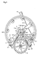
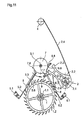
- the figure 1 illustrates in plan from above a general view of the free escape mechanism without being represented the other elements of the watch movement such as platinum and bridges, wheel etc. to avoid overloading the drawings and to facilitate understanding of the exhaust mechanism that constitutes the present invention.
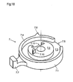
- the plate 7 is constituted in the illustrated example of a large plate 7.1 and a small plate 7.2 (see figure 18 ).
- the large plate 7.1 comprises a plate 7.3 comprising fixing means for example a hole to be driven on the balance shaft 3.1 and a peripheral skirt 7.4.
- This skirt 7.4 has an opening 7.5 and a release nose 7.6 projecting radially on the outer peripheral face of this skirt 7.4.
- This release nose 7.6 is intended to cooperate with the first detent 5.
- the plate 7.3 of the large plate 7.1 comprises on its periphery a pulse pin 7.7 intended to cooperate with the fork 2.3 of the pulse wheel 2.
- the lower face of the small plate 7.2 carries a release pin 7.10 intended to cooperate with the second trigger 6.
- This small plate also has on its periphery a clearance 7.11 intended to cooperate with the second trigger 6.
- the first relaxation 5 ( figure 16 ) has a fixing stud 5.1 for fixing on a fixed part of the clockwork movement, an elastic portion 5.2 connecting the attachment stud 5.1 to a rigid portion 5.3 having a rest surface 5.4 intended to cooperate with the teeth of the escape wheel 1.2.
- This rigid portion 5.3 extends favorably towards the plate 7 and has at its end a finger 5.5 disposed at rest, the trigger 5 blocking the escape wheel, between the skirt 7.4 of the large plateau and the periphery of the small plateau 7.2.
- a leaf spring 5.6 is fixed at one end to the rigid portion 5.3 of the first trigger 5 and extends towards the plate 7 to end in a free end having a pallet 5.7 of greater width than the first trigger 5 and intended to cooperate with the release nose 7.6 of the plate 7.
- the second detent 6 comprises a fixing stud 6.1 and a flexible portion 6.2 connecting this fixing stud 6.1 to a rigid portion 6.3 extending partially under the toothing of the escape wheel 1.2 and whose side face 6.4 opposite to the axis of the escapement mobile 1, cooperates with the hook 2.6 of the mobile pulse 2.
- the rest position of the second trigger 6 is determined by a second stop 9 against which this second trigger is supported by its own elasticity.
- the free end of this second trigger 6 comprises two branches 6.5, 6.6 going away from one another.
- the end of the first branch 6.5 has a lug 6.7 extending inside the skirt 7.4 of the plate 7 and cooperating with the outer peripheral face of the small plate 7.2 and its clearance 7.11.
- the end of the second branch 6.6 of the second trigger 6 carries a release spring 6.8 extending substantially tangentially to the path of the release pin 7.10 of the plate 7.
- the end of this release spring 6.8 advantageously forms a hook for to limit the maximum deflection of the release spring 6.8, this avoiding a plastic deformation or the breaking of said spring 6.8.
- this second trigger 6 In the rest position this second trigger 6 is in abutment against a second stop 9 secured to a fixed part of the watch movement. In this rest position, the lateral face 6.4 of this second trigger 6 is not in contact with the hook 2.6 of the impulse wheel and the hook 2.6 rests on one of the teeth of the escape wheel 1.2.
- the detents 5 and 6 and the impulse mobile 2 are assembled under prestressing, armed, which allows to have very simple dimension chains for the tolerance calculations because most of the fluctuations are offset by the elasticity of these elements. .
- the escape wheel 1.2 is indexed by the first trigger 5 and this escape wheel itself indexes the pulse wheel 2.
- a single correction can be envisaged during the completion, it is the centering of the pulse wheel 2 with respect to the straight line connecting the pivot points of the pulse wheel 2 and the balance 3 so that the range 2.3 from mobile pulse 2 is positioned symmetrically with respect to said straight line.
- This adjustment of the positioning of the pulse mobile can be done by an eccentric head screw.
- the first trigger 5 can slide linearly along its longitudinal axis. Linear guidance is favorably performed by a flexible guide with parallel springs prestressed against the eccentric screw.
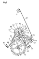
- the escape wheel 1.2 is stationary and rests by one of its teeth on the rest surface 5.4 of the first trigger 5 ( figures 2 and 16 ).
- the pendulum 3 crosses its additional arc descending to the point of elongation of 25 °.
- the impulse pin 7.7 of the plate 7 enters the range 2.3 of the impulse mobile 2 without touching it.
- the release nose 7.6 of the plate 7 comes into contact with the leaf spring 5.6 of the first trigger 5 and pushes this leaf spring 5.6 and all the first trigger whose flexible portion 5.2 flexes to move the resting surface 5.4 away from the tooth of the escape wheel 1.2 with which it is in contact.
- the rest surface 5.4 slides substantially radially on the tooth of the escape wheel 1.2. During this sliding the escape wheel 1.2 does not move yet, the first trigger 5 travels the rest distance, safety necessary to guarantee the locking of the escape wheel despite imperfections of the components due to manufacturing tolerances.
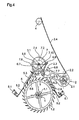
- the escape wheel accelerates driven that it is by the barrel and the gear of the watch movement.
- the rotation of the escape wheel 1.2 drives the impulse wheel 2 by its hook 2.6 which is always in engagement with a tooth of the escape wheel 1.2.
- the fork 2.3 of the impulse mobile 2 catches the impulse pin 7.7 of the plate 7 and transmits a pulse to the balance until the next tooth of the escape wheel 1.2 comes to rest on the rest surface 5.4 of the first trigger which once it has escaped the release nose 7.6 of the plate 7 has returned to rest position under the effect of its own elasticity in contact with the escape wheel.
- the escape wheel 1.2 is again blocked ( figure 4 ).
- the figure 13 illustrates the torque C transmitted to the balance 3 by the pulse wheel 2 during the arming phase as a function of the angle ⁇ of the angular displacement of the pulse wheel 2.
- C2 represents the torque at the pulse wheel 2 set to disposal by the escape wheel when the barrel of the watch movement is fully armed.
- C1 represents the torque available at the end of the barrel power reserve. Whatever the winding of the barrel, we therefore always have at least the torque C 1 available to transmit energy to the balance 3.
- the impulse wheel 2 receives from the escape wheel 1.2 by its hook 2.6 a torque at least equal to C1.
- This pair switches the impulse wheel 2 from its position ⁇ 0 (fork 2.3 on the left) to position ⁇ 1 (fork 2.3 on the right).
- a part (E var + E 1 ) of the energy transmitted to the impulse mobile is transmitted by the range 2.3 thereof to the impulse pin 7.7 and therefore to the balance 3 while another part E2 of the available energy is used to arm the impulse spring 2.4 of the impulse mobile.
- the distribution between the energy E1 transmitted to the beam and the E2 used to arm the spring 2.4 of the pulse wheel 2 depends on the characteristic or constant K of this spring 2.4 as can be seen by comparing the Figures 13 and 14 .
- the slope of the characteristic curve of the spring 2.4 modifies the distribution of energy over time between the pulse given to the balance 3 and the armature of the mobile spring 2.4. pulse 2 during the arming phase.
- Figures 13 and 14 show the line "0" linking the center of rotation of the balance 3 to the center of rotation of the impulse mobile 2. This line, perfectly centered between the extreme positions ⁇ 0 and ⁇ 1 of the impulse mobile, also corresponds to the position the theoretical dead point of the oscillator.
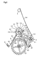
- the release pin 7.10 of the plate 7 slides on the release spring 6.8 of the second trigger 6 and forces this second detent against the second stop 9. In doing so the release spring 6.8 is deformed to let the release pin 7.10 then returns to the rest position.
- the impulse pin 7.7 of the plate 7 leaves the fork 2.3 of the impulse mobile 2 and the pendulum carries out its additional ascending arc with a clockwise movement to the point of return of the pendulum 3.
- the second alternation or mute phase will be described below.
- the escape wheel 1.2 remains at rest throughout this phase supported by one of its teeth on the rest surface 5.4 of the first trigger 5. As a result the wheel does not move either.
- the balance returns counterclockwise from its additional arc ( figure 5 ).
- the release peg 7.10 of the plate 7 comes into contact with the driving abutment 6.9 of the second detent 6 and displaces this second detent 6 by bending its elastic portion 6.2 in the direction of the pulse wheel 2 driving through its lateral face 6.4 the hook 2.6 of the mobile 2.
- the hook 2.6 of the impulse wheel slides on the tooth of the escape wheel 1.2 and after having traveled the rest distance this hook 2.6 escapes the escape wheel 1.2 and releases the mobile of impulse 2 ( figure 6 ).
- Pulse wheel 2 pivots clockwise under the action of its pulse spring 2.4 which was armed during the arming phase.
- the range 2.3 of the impulse mobile 2 catches the impulse pin 7.7 of the plate 7 and transmits a pulse to the pendulum 3.
- the release pin 7.10 of the plate 7 escapes the driving abutment 6.9 of the second trigger 6 and the latter returns to the rest position against the second stop 9 by its own elasticity ( figure 7 ).
- the energy E2 transmitted to the balance 3 by the pulse wheel 2 during this silent phase is the one that the spring 2.4 of the mobile pulse 2 had stored during the winding phase.
- the release nose 7.6 of the plate 7 passes the first detent 5 by deformation of its leaf spring 5.6 ( figure 8 ).
- the impulse pin 7.7 of the plate 7 leaves the fork 2.3 of the impulse mobile 2 and the rocker performs its additional arc ascending with a counterclockwise movement to the point of return.
- the mechanism is found in the position illustrated in figure 2 and a new cycle can begin.
- this escape mechanism comprises an escape wheel, a pulse mobile and control means.
- the escape wheel transmits, during an alternation of the pendulum, the energy of the barrel impulse mobile that arms his spring and transmits a portion of the energy received pendulum.
- the impulse mobile transmits to said balance of the energy supplied by its pulse spring previously armed during the previous alternation.
- This exhaust mechanism thus achieves a blowout escape in which there is necessarily a power transmission to the balance during each alternation thereof.
- the impulse spring 2.4 of the impulse wheel 2 can be produced in different ways, for example by a spiral spring or as in the example described by a leaf spring, which makes it possible to obtain as flat a possible assembly as possible that a characteristic or high slope of the elasticity curve of this spring.
- the high stiffness of the impulse spring 2 pulse pulse 2 causes a strong pulse before the dead point that it delivers immediately to the pulse. oscillator here the balance-spiral. The energy losses due to the clearance are thus immediately compensated.
- the torque of the impulse spring 2.4 of the mobile pulse 2 armed is only slightly lower than the torque transmitted by the wheel, there is almost a balance of strength.
- the driving force must necessarily be greater than the maximum torque of the impulse spring 2.4 pulse 2 to ensure the complete arming of the pulse spring and the impulse mobile and the proper positioning of the moving parts of the mechanism.
- the maximum torque on the pulse wheel 2 does not exceed 95% of the minimum torque, at the end of the power reserve, provided by the escape wheel 1.2.
- the exhaust uses a portion of the energy available to arm the spring 2.4 which gradually decreases the kinetic energy of the escape wheel by the increasing resistance of the spring 2.4 instead of damping said kinetic energy entirely by the shock of the exhaust wheel entering full speed in abutment with the pallet of the steering element (anchor or trigger) and causing the ticking of the movement.
- the escape wheel 1.2 does not recoil.
- the control elements that are the two detents 5 and 6 are prestressed and find their rest position after shock thanks to their own elasticity.
- This exhaust mechanism makes it possible to significantly increase the number of teeth of the escape wheel without increasing its diameter. It is possible to double or more the number of teeth of the escape wheel compared to a classic anchor escapement without increasing the diameter. It is then possible to use this escapement mechanism with a high frequency oscillator, 5 Hertz or more, without the need to provide an additional mobile between the second wheel and the exhaust pinion and without the need for additional reports. gearing to maintain the angular velocity imposed by the second wheel. In fact, a large reduction is already achieved by the fact that the escape wheel advances only one step for two alternations of the oscillator and the fact of being able to increase the number of teeth in a given diameter of the wheel. exhaust through the use of the impulse mobile 2.
- the escape mechanism is self-starting because the oscillator receives energy during each of its alternations.
- the present escapement mechanism makes it possible to influence the chronometric behavior of the escapement at will and to eliminate the run-out errors due to the escapement or to balance other isochronism defects, for example originating from the spiral, by an adjustment of the exhaust mechanism. Indeed in this escape mechanism it is possible to adjust and adjust the temporal distribution of energy supplied to the balance in the arming phase and in the dummy phase relative to the neutral point of the oscillator by playing on the stiffness or elastic characteristic of the impulse spring 2.4 of the impulse mobile. It is thus possible by choosing the characteristic of this impulse spring 2.4 of the impulse mobile to obtain an escapement exhibiting neither advance nor chronometric delay.
- the cogwheel of the clockwork movement equipped with it advances only once per period, ie during alternating half of the oscillator. During the silent alternation the gear does not turn, although the oscillator receives a pulse. This reduces the energy loss due to the inertia of the gear when it is started.
- the impulse wheel and the escape wheel are almost in force balance. This feature allows to recover the kinetic energy stored in the wheel.
- the impulse spring 2.4 of the mobile of pulse 2 is almost discharged before the hook 2.6 of said mobile pulse 2 does not fall on a tooth of the escape wheel, there will also be less energy dissipated.
- the present exhaust mechanism is particularly well adapted to be integrated in the cages of a vortex at high oscillator frequency, because it allows despite the use of a high frequency oscillator the conservation of a gear ratio Ordinary because of the large number of teeth of the escape wheel and moreover, it allows to recover the kinetic energy of the wheel including vortex cages.
- the escapement mechanism is intended to equip watch movements which comprise a frame on which a barrel is mounted, a gear train kinematically connecting this barrel with an escape wheel and an oscillator provided with of a pendulum.
- This escapement mechanism comprises an escape wheel forming part of the escape wheel and a plate secured to the axis of the balance comprising a pulse pin.
- control means comprise control members carried by the plate 7 formed in the example illustrated by the release nose 7.6 and the release pin 7.10.
- control means further comprise either an anchor or, as in the example shown, two detents controlled by said control members.
- the escape mechanism according to the invention also comprises security devices carried by the plate 7, in the example illustrated the skirt 7.4 of the large plate and the periphery of the small plate 7.2, preventing any inadvertent movement, for example under the effect of shocks, control means of the mechanism.
- the pulse spring of the impulse mobile can be realized in different ways, a blade spring as in the example described but also a spiral spring or a coil spring.
- the arm, terminated by a hook, of the impulse can be an elastic arm as in the example described or realized by a connecting rod articulated on the body of the impulse mobile and constrained against the escape wheel by a spring or still be realized by a linear guide.
- the impulse spring 2.4 of the impulse mobile could be removably attached to the body 2.2 of the impulse mobile to be able to adapt to this impulse mobile a pulse spring corresponding to the energy that we want transmit to the pendulum during the second alternations of it as has been explained in relation to the Figures 13 and 14 .
- control means and safety devices may be different from that described in the illustrated example provided that the functions necessary for the operation of the exhaust mechanism according to the invention are realized.
- the frequency of the oscillator can be different from 5 Hertz, for example 3 or 4 Hertz. In other variants the frequency can be higher than 5 Hertz.
- this escapement mechanism for a timepiece is intended to transmit to a mechanical oscillator pulses once alternately to maintain its movement.
- An escape wheel provides as it advances by one step during a first alternation of the oscillator the total energy necessary to maintain the movement of the oscillator during two successive alternations of the oscillator and that this oscillator receives during a first alternation only a part of the energy and that the other part of this total energy is stored by a mobile pulse to be transmitted to the oscillator during a second alternation of it.
- control means cause the loss of contact between the escape wheel and the impulse wheel during the second alternation of the oscillator during which the impulse wheel returns to a first position ( ⁇ 1) under the effect of the energy stored during the first alternation of the oscillator while transmitting a portion of this energy to said oscillator during its second alternation.
- this impulse mobile is connected to the frame of the movement of the timepiece by a prestressed elastic element, in the example illustrated the pulse spring 2.4.
- the invention also relates to monobloc detents for themselves as described and illustrated in FIGS. Figures 16 and 17 but may of course be used in other types of exhaust than that described in the foregoing.
- the existing detents for escapes of watch movements are complex and formed of several pieces assembled.
- the one-piece detents described with reference to this escapement are simple, easy to machine with modern machining methods (DRIE) and can of course be used on all types of escapements.
- DRIE modern machining methods
- One of their originalities is to be made in one piece.
- Another of their originalities is that they each have two portions 5.2, 5.6 or 6.2, 6.8 elastics.
- these detents can be manufactured in brittle materials, not plastically deformable, such as silicon for example.
- the flexible blade forming the release spring 6.8 being tangential to the trajectory of the release pin 7.10, there is no catch-up effect as for the first relaxation 5.
- the release is immediate.
- This second relaxation 6 can also be performed by the DRIE method and be monobloc.
- this second trigger can also be secured by a skirt that would replace the cam 7.2 or small plateau tray 7 described above.
Landscapes
- Physics & Mathematics (AREA)
- General Physics & Mathematics (AREA)
- Measurement Of Unknown Time Intervals (AREA)
- Micromachines (AREA)
- Vibration Prevention Devices (AREA)
Abstract
Description
La présente invention se rapporte aux mécanismes d'échappement libre pour mouvement d'horlogerie.The present invention relates to free escapement mechanisms for clockwork.
Les échappements libres sont aujourd'hui reconnus comme le meilleur moyen pour l'entretien des oscillations d'un système balancier-spiral,Free exhausts are nowadays recognized as the best way for the maintenance of the oscillations of a system balance-spiral,
Les échappements libres pour mouvements d'horlogerie existants peuvent être répertoriés en deux catégories principales selon leurs moyens de pilotage :
- les échappements à détente ; et
- les échappements à ancre.
- escapements with relaxation; and
- anchor escapements.
Les échappements à détente sont des échappements à impulsion directe. La détente est une pièce d'arrêt n'ayant qu'une seule position de repos.Expansion exhausts are direct impulse exhausts. The trigger is a stop with only one rest position.
La roue d'échappement donne une impulsion par période à l'oscillateur sans avoir besoin d'un élément intermédiaire. Par conséquent, le rouage n'avance qu'une fois par période. Une période d'un oscillateur consiste de deux alternances. Du au manque d'impulsion lors de la phase muette, les échappements à détente ne sont pas auto-démarrant.The escape wheel gives a pulse per period to the oscillator without the need for an intermediate element. As a result, the wheel goes forward only once per period. A period of an oscillator consists of two alternations. Due to the lack of impulse during the silent phase, the expansion exhausts are not self-starting.
Les échappements à ancre existent soit avec impulsion directe de la roue d'échappement au balancier, soit à impulsion indirecte par l'intermédiaire de l'ancre.Anchor escapements exist either with a direct impulse from the escapement wheel to the pendulum or indirectly by means of the anchor.
L'ancre est une pièce d'arrêt qui a deux positions de repos. Les échappements à ancre font avancer le rouage une fois par alternance. Seule exception fait l'échappement à ancre à coup perdu, ou la roue d'échappement tombe lors de la phase dite "muette" sur une deuxième surface de repos. Lors de cette phase muette, les échappements à coup perdu connus ne peuvent pas transmettre d'énergie à l'oscillateur. La phase muette, même qu'elle fait avancer le rouage très peu, à pour but de faire sauter l'aiguille des secondes une fois par période de l'oscillateur.The anchor is a stopping piece that has two resting positions. Anchor escapements advance the gear once in a row. The only exception is the lever escapement, or the escape wheel falls during the so-called "dumb" phase on a second resting surface. During this silent phase, the known bleed escapements can not transmit energy to the oscillator. The silent phase, even as it moves the wheel very little, aims to blow the seconds hand once per period of the oscillator.
La plupart des échappements à ancre transmettent l'énergie indirectement par l'intermédiaire de l'ancre.Most anchor escapements transmit energy indirectly through the anchor.
Tous les échappements libres connus ont en commun, que la roue d'échappement, une fois dégagée, accélère et transmet de l'énergie à l'oscillateur avant d'amortir son mouvement sur la palette de repos. Cet amortissement d'énergie constitue une perte d'énergie considérable et est bien audible étant une des origines du tic-tac d'une montre.All known free exhausts have in common, that the escape wheel, once released, accelerates and transmits energy to the oscillator before damping its movement on the pallet rest. This energy damping is a considerable loss of energy and is well audible being one of the origins of ticking a watch.
La plupart des échappements à ancre ou à détente ont besoin d'une chute entre le dégagement et l'impulsion et/ou entre l'impulsion et le repos. Cette chute est indispensable comme sécurité pour remédier aux tolérances de fabrication. Elle a pour but d'éviter l'accrochement de surfaces fonctionnelles dues aux variations dimensionnelles des composants. Au moins la chute après l'impulsion est une pure perte d'énergie. Elle ne sert qu'à produire le tic-tac bien fort mentionné ci-dessus.Most anchor or expansion escapements require a fall between clearance and impulse and / or pulse and rest. This fall is essential as a security to overcome manufacturing tolerances. It aims to avoid the attachment of functional surfaces due to dimensional variations of the components. At least the fall after the impulse is a pure loss of energy. It only serves to produce the strong ticking mentioned above.
Le but de la présente invention est de réaliser un mécanisme d'échappement libre pour mouvement d'horlogerie dont le pilotage puisse se faire soit par des détentes soit par une ancre qui soit applicable aux pièces d'horlogerie portables et qui transmette de l'énergie à l'oscillateur à chaque alternance de celui-ci tout en permettant de réduire les pertes d'énergie, de réduire les influences inertielles et de rendre l'échappement insensible aux chocs. Un autre but est de réduire ou supprimer les chutes consommatrices d'énergie.The object of the present invention is to provide a free escapement mechanism for a clockwork movement that can be controlled either by detents or by an anchor that is applicable to portable timepieces and transmits energy. oscillator at each alternation of it while reducing energy losses, reduce inertial influences and make the exhaust insensitive to shocks. Another goal is to reduce or eliminate energy-consuming falls.
La présente invention a pour objet un mécanisme d'échappement libre pour mouvements d'horlogerie d'une pièce d'horlogerie portable notamment d'une montre bracelet ou de poche qui se distingue par un mécanisme d'échappement destiné à équiper des mouvements d'horlogerie qui comprennent un bâti sur lequel sont montés un barillet, un rouage reliant cinématiquement ce barillet à un mobile d'échappement et un oscillateur muni d'un balancier; ce mécanisme d'échappement comportant une roue d'échappement faisant partie du mobile d'échappement et un plateau, solidaire d'un axe sur lequel est monté le balancier comportant une cheville d'impulsion; caractérisé par le fait que ce mécanisme d'échappement comporte encore:
- un mobile d'impulsion pivoté sur le bâti du mouvement d'horlogerie comportant une fourchette d'impulsion agencée pour coopérer avec la cheville d'impulsion du plateau; un ressort d'impulsion; et un bras terminé par un crochet adapté à coopérer avec la denture de la roue d'échappement; et
- des moyens de pilotage agencés pour libérer la roue d'échappement d'un pas pendant des premières alternances du balancier s'effectuant dans un premier sens de rotation, et dégageant le crochet du mobile d'impulsion de la denture de la roue d'échappement pendant des secondes alternances du balancier s'effectuant dans un second sens de rotation opposé au premier sens de rotation.
- a pulse mobile rotated on the clockwork frame having a pulse fork arranged to cooperate with the pin pulse of the plate; a pulse spring; and an arm terminated by a hook adapted to cooperate with the toothing of the escape wheel; and
- control means arranged to release the escape wheel by one step during the first half-waves of the balance being effected in a first direction of rotation, and releasing the hook of the impulse mobile from the toothing of the escape wheel during second alternations of the pendulum in a second direction of rotation opposite to the first direction of rotation.
L'invention a également pour objet un mouvement et/ou pièce d'horlogerie incorporant un tel mécanisme d'échappement.The invention also relates to a movement and / or timepiece incorporating such an exhaust mechanism.
En outre la présente invention a également pour but la réalisation de détentes simples et faciles à réaliser. L'invention a donc également pour objet une détente, notamment pour un mécanisme d'échappement qui se distingue par le fait qu'elle est monobloc c'est-à-dire réalisée en une seule pièce.In addition, the present invention also aims at the realization of simple and easy to achieve relaxation. The invention therefore also relates to an expansion, particularly for an exhaust mechanism which is distinguished by the fact that it is monobloc that is to say made in one piece.
Le dessin annexé illustre schématiquement et à titre d'exemple une forme d'exécution particulière du mécanisme d'échappement libre pour mouvement d'horlogerie.
- La
figure 1 illustre schématiquement en plan de dessus les éléments principaux du mécanisme d'échappement libre nécessaire pour illustrer son fonctionnement. - Les
figures 2 à 8 illustrent le mécanisme d'échappement libre de lafigure 1 , le balancier ayant été enlevé pour plus de clarté, dans différentes positions du cycle de fonctionnement. - La
figure 9 illustre un dispositif de sécurité prévu pour éviter les dégagements intempestifs d'une première détente en cas de chocs. - La
figure 10 illustre un dispositif de sécurité prévu pour éviter des dégagements intempestifs d'une seconde détente en cas de chocs. - Les
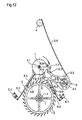
figures 11 et12 illustrent un dispositif de sécurité évitant le galop du mécanisme d'échappement lorsque le balancier effectue son arc supplémentaire de la phase muette respectivement de la phase d'armage du mécanisme. - Les
figures 13 et 14 illustrent la transmission d'énergie pour deux comportements chronométriques différents du mécanisme d'échappement. - La
figure 15 est une vue isométrique de dessus du mécanisme d'échappement illustré à lafigure 1 , le balancier étant retiré pour une meilleure illustration. - La
figure 16 est une vue isométrique de la première détente des moyens de pilotage. - La
figure 17 est une vue isométrique de la seconde détente des moyens de pilotage. - La
figure 18 est une vue isométrique d'un plateau solidaire de l'axe du balancier.
- The
figure 1 schematically illustrates in plan from above the main elements of the free escape mechanism necessary to illustrate its operation. - The
Figures 2 to 8 illustrate the free escape mechanism of thefigure 1 , the balance having been removed for greater clarity, in different positions of the operating cycle. - The
figure 9 illustrates a safety device designed to prevent untimely releases a first trigger in case of shocks. - The
figure 10 illustrates a safety device provided to prevent untimely release of a second trigger in case of shocks. - The
figures 11 and12 illustrate a safety device avoiding the gallop of the escapement mechanism when the pendulum performs its additional arc of the mute phase respectively of the arming phase of the mechanism. - The
Figures 13 and 14 illustrate the transmission of energy for two different chronometric behaviors of the escape mechanism. - The
figure 15 is an isometric view from above of the escape mechanism illustrated infigure 1 , the balance being removed for a better illustration. - The
figure 16 is an isometric view of the first detent of the control means. - The
figure 17 is an isometric view of the second detent of the control means. - The
figure 18 is an isometric view of a plate integral with the axis of the balance.
Le mécanisme d'échappement libre selon l'invention est un échappement dans lequel la roue d'échappement n'effectue qu'un pas par oscillation du balancier comme dans les mécanismes d'échappement à coup perdu à la différence que dans le présent mécanisme le balancier reçoit deux impulsions par oscillation, une par alternance, ce qui n'est pas le cas dans un échappement à coup perdu classique.The free escapement mechanism according to the invention is an escapement in which the escapement wheel makes only one step by oscillation of the balance wheel as in the blow-back exhaust mechanisms, with the difference that in the present mechanism the pendulum receives two impulses per oscillation, one alternately, which is not the case in a classic escapement.
Dans ce qui suit la forme d'exécution illustrée au dessin va être décrite, cette forme d'exécution du mécanisme d'échappement libre selon l'invention est pilotée par deux détentes. Il s'agit là d'une forme d'exécution préférée car elle donne les meilleurs résultats du point de vue énergétique et du rendement du mécanisme mais il est évident que dans d'autres formes d'exécution ce mécanisme d'échappement pourrait être piloté par d'autres moyens de pilotage par exemple par une ancre. Il est à noter toutefois que dans ce cas l'ancre ne sert qu'au pilotage de l'échappement, c'est-à-dire que l'ancre ne participe pas à la transmission d'énergie de la roue d'échappement à l'axe du balancier.In what follows the embodiment shown in the drawing will be described, this embodiment of the free escape mechanism according to the invention is controlled by two detents. This is a preferred embodiment because it gives the best results in terms of energy and efficiency of the mechanism but it is obvious that in other embodiments this exhaust mechanism could be controlled. by other control means for example by an anchor. It should be noted, however, that in this case the anchor serves only to control the exhaust, that is to say that the anchor does not participate in the energy transmission of the escape wheel to the axis of the pendulum.
La
Ce mécanisme d'échappement libre se compose :
- d'un
mobile d'échappement 1 formé du pignon d'échappement 1.1 de neuf dents et de la roue d'échappement 1.2 comportant trente dents dans l'exemple illustré. Cemobile d'échappement 1 est pivoté sur des parties fixes d'un mouvement d'horlogerie. - d'un
mobile d'impulsion 2 composé d'un axe d'impulsion 2.1 et d'un corps d'impulsion 2.2 chassé sur l'axe d'impulsion 2.1. Cemobile d'impulsion 2 est également pivoté sur les parties fixes d'un mouvement d'horlogerie. Cemobile d'impulsion 2 comporte à son extrémité une fourchette 2.3. Lemobile d'impulsion 2 comporte encore un ressort d'impulsion 2.4 dont l'extrémité libre prend appui sur une première butée 4 solidaire d'une partie fixe du mouvement d'horlogerie. Ce mobile d'impulsion est enfin muni d'un bras élastique 2.5 se terminant par un crochet 2.6 présentant une face de repos. L'élasticité du bras élastique 2.5 tend à appliquer le crochet 2.6 contre la denture de la roue d'échappement 1.2 et cette face de repos du crochet 2.6 positionne lemobile d'impulsion 2 par rapport à ladite roue d'échappement 1.2 qui est entraînée par son pignon d'échappement 1.1 relié par le rouage du mouvement (non illustré) au barillet du mouvement (non illustré).
- de moyens de pilotage du mécanisme d'échappement comportant une première
détente 5 et une seconde détente 6 fixées sur une partie fixe du mouvement d'horlogerie et coopérant avecun plateau 7 solidaire de l'axe 3.1d'un balancier 3 d'un oscillateur formé d'un balancier-spiral. La serge 3.2 du balancier 3 est rivée sur l'axe de balancier 3,1 et leplateau 7 est chassé sur ledit axe de balancier 3.1, Le spiral de cet oscillateur n'est pas représenté. L'oscillateur, soit le balancier-spiral, est bien connu dans l'état de l'art et pivote également entre des parties fixes du mouvement d'horlogerie. Dans l'exemple illustré, l'oscillateur possède une fréquence de 5 Hertz.
- an
exhaust mobile 1 formed of the exhaust pinion 1.1 of nine teeth and the escape wheel 1.2 having thirty teeth in the illustrated example. This escapement mobile 1 is pivoted on fixed parts of a clockwork movement. - a pulse mobile 2 composed of a pulse axis 2.1 and a pulse body 2.2 driven on the pulse axis 2.1. This impulse mobile 2 is also rotated on the fixed parts of a clockwork movement. This
mobile pulse 2 has at its end a range 2.3. The impulse mobile 2 further comprises a pulse spring 2.4 whose free end is supported on afirst abutment 4 integral with a fixed part of the watch movement. This mobile pulse is finally equipped with a 2.5 elastic arm se ending with a hook 2.6 having a rest face. The elasticity of the elastic arm 2.5 tends to apply the hook 2.6 against the toothing of the escape wheel 1.2 and this rest face of the hook 2.6 positions the movingpulse 2 relative to said escape wheel 1.2 which is driven by its escape pinion 1.1 connected by the gear of the movement (not shown) to the barrel of the movement (not shown).
- control means of the exhaust mechanism comprising a
first detent 5 and asecond detent 6 fixed on a fixed part of the watch movement and cooperating with aplate 7 integral with the axis 3.1 of abalance 3 of an oscillator formed of a sprung balance. The serge 3.2 of thebalance 3 is riveted on the balance shaft 3.1 and theplate 7 is driven on said balance shaft 3.1, The spiral of this oscillator is not shown. The oscillator, the balance spring, is well known in the state of the art and also pivots between fixed parts of the watch movement. In the illustrated example, the oscillator has a frequency of 5 Hertz.
Le plateau 7 est constitué dans l'exemple illustré d'un grand plateau 7.1 et d'un petit plateau 7.2 (voir
Le grand plateau 7.1 comporte une planche 7.3 comprenant des moyens de fixation par exemple un trou pour être chassé sur l'axe de balancier 3.1 et une jupe périphérique 7.4. Cette jupe 7.4 présente une ouverture 7.5 et un nez de dégagement 7.6 faisant saillie radialement sur la face périphérique externe de cette jupe 7.4. Ce nez de dégagement 7.6 est destiné à coopérer avec la première détente 5. La planche 7.3 du grand plateau 7.1 comporte sur sa périphérie une cheville d'impulsion 7.7 destinée à coopérer avec la fourchette 2.3 du mobile d'impulsion 2.The large plate 7.1 comprises a plate 7.3 comprising fixing means for example a hole to be driven on the balance shaft 3.1 and a peripheral skirt 7.4. This skirt 7.4 has an opening 7.5 and a release nose 7.6 projecting radially on the outer peripheral face of this skirt 7.4. This release nose 7.6 is intended to cooperate with the
La face inférieure du petit plateau 7.2 porte une cheville de dégagement 7.10 destinée à coopérer avec la seconde détente 6. Ce petit plateau comporte encore sur sa périphérie un dégagement 7.11 destiné à coopérer avec la seconde détente 6.The lower face of the small plate 7.2 carries a release pin 7.10 intended to cooperate with the
La première détente 5 (
La seconde détente 6 comporte un plot de fixation 6.1 et une portion flexible 6.2 reliant ce plot de fixation 6.1 à une portion rigide 6.3 s'étendant partiellement sous la denture de la roue d'échappement 1.2 et dont la face latérale 6.4 opposée à l'axe du mobile d'échappement 1, coopère avec le crochet 2.6 du mobile d'impulsion 2. La position de repos de cette seconde détente 6 est déterminée par une seconde butée 9 contre laquelle cette seconde détente s'appuie de par son élasticité propre. L'extrémité libre de cette seconde détente 6 comporte deux branches 6.5, 6.6 allant en s'écartant l'une de l'autre. L'extrémité de la première branche 6.5 comporte un ergot 6,7 s'étendant à l'intérieur de la jupe 7.4 du plateau 7 et coopérant avec la face périphérique externe du petit plateau 7.2 et son dégagement 7.11.The
L'extrémité de la seconde branche 6.6 de la seconde détente 6 porte un ressort de dégagement 6.8 s'étendant sensiblement tangentiellement au trajet de la cheville de dégagement 7.10 du plateau 7. L'extrémité de ce ressort de dégagement 6.8 forme favorablement un crochet pour limiter le fléchissement maximal du ressort de dégagement 6.8, ceci évitant une déformation plastique ou la casse dudit ressort 6.8. En position de repos cette seconde détente 6 est en appui contre une seconde butée 9 solidaire d'une partie fixe du mouvement d'horlogerie. Dans cette position de repos la face latérale 6.4 de cette seconde détente 6 n'est pas en contact avec le crochet 2.6 du mobile d'impulsion et le crochet 2.6 repose sur une des dents de la roue d'échappement 1.2.The end of the second branch 6.6 of the
Les détentes 5 et 6 ainsi que le mobile d'impulsion 2 sont assemblés sous précontrainte, armés, ce qui permet de disposer de chaînes de cotes très simples pour les calculs de tolérance car la plupart des fluctuations sont compensées par l'élasticité de ces éléments. La roue d'échappement 1.2 est indexée par la première détente 5 et cette roue d'échappement indexe elle-même le mobile d'impulsion 2.The
En cas de besoin une seule correction peut être envisagée lors de l'achevage, c'est le centrage du mobile d'impulsion 2 par rapport à la droite reliant les points de pivotement du mobile d'impulsion 2 et du balancier 3 pour que la fourchette 2.3 du mobile d'impulsion 2 soit positionnée symétriquement par rapport à ladite droite. Ce réglage du positionnement du mobile d'impulsion peut se faire par une vis à tête excentrique. Pour ce faire, la première détente 5 peut coulisser linéairement le long de son axe longitudinal. Le guidage linéaire est effectué favorablement par un guidage flexible avec des ressorts parallèles précontraints contre la vis excentrique.If necessary, a single correction can be envisaged during the completion, it is the centering of the
Le fonctionnement de ce mécanisme d'échappement comporte deux phases principales :
- premièrement la phase d'armage pendant la première alternance du balancier pendant laquelle la roue d'échappement et tout le rouage du mouvement d'horlogerie avance d'un pas,
- deuxièmement la phase muette pendant la seconde alternance du balancier pendant laquelle la roue d'échappement et tout le rouage du mouvement d'horlogerie ne bouge pas.
- firstly the arming phase during the first alternation of the balance during which the escape wheel and all the gear of the watch movement advances one step,
- secondly, the silent phase during the second alternation of the pendulum during which the escape wheel and all the wheels of the watch movement do not move.
Néanmoins pendant chacune de ces deux phases, phase d'armage et phase muette, une quantité déterminée d'énergie est transmise au balancier par l'intermédiaire du mobile d'impulsion qui lui reçoit l'énergie à transmettre soit directement par la roue d'échappement pendant la phase d'armage soit par son ressort d'impulsion pendant la phase muette.Nevertheless, during each of these two phases, the arming phase and the silent phase, a determined quantity of energy is transmitted to the balance by means of the impulse wheel which receives the energy to be transmitted directly by the impeller. exhaust during the arming phase either by its pulse spring during the silent phase.
En référence aux
Supposons que le balancier 3 revient en sens horaire de son point de retour. La roue d'échappement 1.2 est immobile et repose par une de ses dents sur la surface de repos 5.4 de la première détente 5 (
Une fois dégagée de la surface de repos 5.4 de la première détente 5 (
La
Pendant cette phase d'armage le mobile d'impulsion 2 reçoit de la roue d'échappement 1.2 par son crochet 2.6 un couple au moins égal à C1. Ce couple fait basculer le mobile d'impulsion 2 de sa position α0 (fourchette 2.3 à gauche) en position α1 (fourchette 2.3 à droite). Une partie (Evar + E1) de l'énergie transmise au mobile d'impulsion est transmise par la fourchette 2.3 de celui-ci à la cheville d'impulsion 7.7 et donc au balancier 3 tandis qu'une autre partie E2 de l'énergie disponible est utilisée pour armer le ressort d'impulsion 2.4 du mobile d'impulsion. La répartition entre l'énergie E1 transmise au balancier et celle E2 servant à armer le ressort 2.4 du mobile d'impulsion 2 dépend de la caractéristique ou constante K de ce ressort 2.4 comme on le voit en comparant les
La répartition d'énergie entre l'impulsion donnée au balancier et l'énergie stockée dans le ressort 2.4 est équivalente (rapport 1 :1) pour le barillet armé à fond (couple maximal = C2,
Entre les
Pour une meilleure compréhension de ce fait, les
On voit clairement que le ressort 2.4 plus raide (
Lors de l'impulsion, la cheville de dégagement 7.10 du plateau 7 glisse sur le ressort de dégagement 6.8 de la seconde détente 6 et force cette seconde détente contre la seconde butée 9. Ce faisant le ressort de dégagement 6.8 se déforme pour laisser passer la cheville de dégagement 7.10 puis revient en position de repos.During the impulse, the release pin 7.10 of the
La cheville d'impulsion 7.7 du plateau 7 quitte la fourchette 2.3 du mobile d'impulsion 2 et le balancier effectue son arc supplémentaire ascendant avec un mouvement en sens horaire jusqu'au point de retour du balancier 3. En référence aux
La roue d'échappement 1.2 reste au repos pendant toute cette phase en appui par une de ses dents sur la surface de repos 5.4 de la première détente 5. En conséquence le rouage ne bouge pas non plus. Le balancier revient en sens antihoraire de son arc supplémentaire (
La cheville de dégagement 7.10 du plateau 7 échappe à la butée d'entraînement 6.9 de la seconde détente 6 et celle-ci revient en position de repos contre la seconde butée 9 par son élasticité propre (
Le crochet 2.6 du mobile d'impulsion 2, libéré de la seconde détente 6, tombe sur la dent suivante de la roue d'échappement 1.2 et bloque le mobile d'impulsion 2.The hook 2.6 of the
L'énergie E2 transmise au balancier 3 par le mobile d'impulsion 2 lors de cette phase muette est celle que le ressort 2.4 du mobile d'impulsion 2 avait emmagasinée lors de la phase d'armage.The energy E2 transmitted to the
Pendant la phase muette le nez de dégagement 7.6 du plateau 7 passe outre la première détente 5 par déformation de sa lame ressort 5.6 (
La cheville d'impulsion 7.7 du plateau 7 quitte la fourchette 2.3 du mobile d'impulsion 2 et le balancier effectue son arc supplémentaire ascendant avec un mouvement en sens antihoraire jusqu'au point de retour. Le mécanisme se retrouve dans la position illustrée à la
Comme on l'a vu de la description de l'exemple du mécanisme d'échappement, ce mécanisme d'échappement comporte une roue d'échappement, un mobile d'impulsion et des moyens de pilotage. La roue d'échappement transmet, pendant une alternance du balancier, l'énergie du barillet au mobile d'impulsion qui arme son ressort et transmet une partie de l'énergie reçue au balancier. Pendant l'autre alternance du balancier le mobile d'impulsion transmet audit balancier de l'énergie fournie par son ressort d'impulsion préalablement armé lors de l'alternance précédente.As has been seen from the description of the example of the escape mechanism, this escape mechanism comprises an escape wheel, a pulse mobile and control means. The escape wheel transmits, during an alternation of the pendulum, the energy of the barrel impulse mobile that arms his spring and transmits a portion of the energy received pendulum. During the other alternation of the pendulum the impulse mobile transmits to said balance of the energy supplied by its pulse spring previously armed during the previous alternation.
Ce mécanisme d'échappement réalise donc un échappement à coup perdu dans lequel on a nécessairement une transmission d'énergie au balancier pendant chaque alternance de celui-ci.This exhaust mechanism thus achieves a blowout escape in which there is necessarily a power transmission to the balance during each alternation thereof.
La particularité de ce mécanisme d'échappement est qu'il donne une impulsion même pendant la phase muette sans que la roue d'échappement ne tourne. Ceci est obtenu par l'armage du ressort d'impulsion 2.4 du mobile d'impulsion 2 une alternance sur deux, cette énergie emmagasinée dans ledit ressort étant restituée au balancier lors de l'alternance muette.The peculiarity of this escape mechanism is that it gives a pulse even during the silent phase without the escape wheel turning. This is achieved by the winding of the pulse spring 2.4 of the
Le ressort d'impulsion 2.4 du mobile d'impulsion 2 peut être réalisé de différentes manières, par exemple par un ressort spiral ou comme dans l'exemple décrit par un ressort à lame ce qui permet d'obtenir un assemblage le plus plat possible ainsi qu'une caractéristique ou pente élevée de la courbe d'élasticité de ce ressort. Contrairement aux échappements connus qui transmettent la plupart d'énergie à la fin de l'impulsion, la raideur élevée du ressort d'impulsion 2.4 du mobile d'impulsion 2 provoque une forte impulsion avant le point mort qu'il délivre immédiatement à l'oscillateur ici le balancier-spiral. Les pertes d'énergie dues au dégagement sont ainsi immédiatement compensées.The impulse spring 2.4 of the
Ceci est également valable pour les pertes dues au dégagement de la deuxième détente, car les énergies transmises ainsi que leur répartition dynamique sont identiques ou semblables pendant la phase d'armage et la phase muette.This is also true for the losses due to the release of the second expansion, because the transmitted energies and their dynamic distribution are identical or similar during the arming phase and the silent phase.
Le couple du ressort d'impulsion 2.4 du mobile d'impulsion 2 armé n'est que faiblement inférieur au couple transmis par le rouage, on retrouve presque un équilibre de force. La force motrice doit forcement être supérieure au couple maximal du ressort d'impulsion 2.4 du mobile d'impulsion 2 pour assurer l'armage complet de ce ressort d'impulsion et du mobile d'impulsion et le bon positionnement des pièces mobiles du mécanisme. En pratique il est préférable que le couple maximum sur le mobile d'impulsion 2 ne dépasse pas 95% du couple minimal, à la fin de la réserve de marche, fourni par la roue d'échappement 1.2.The torque of the impulse spring 2.4 of the
Ainsi, l'échappement utilise une partie de l'énergie disponible pour armer le ressort 2.4 ce qui diminue progressivement l'énergie cinétique de la roue d'échappement par la résistance croissante du ressort 2.4 au lieu d'amortir ladite énergie cinétique entièrement par le choc de la roue d'échappement rentrant en pleine vitesse en butée avec la palette de l'élément de pilotage (ancre ou détente) et provoquant le tic-tac du mouvement.Thus, the exhaust uses a portion of the energy available to arm the spring 2.4 which gradually decreases the kinetic energy of the escape wheel by the increasing resistance of the spring 2.4 instead of damping said kinetic energy entirely by the shock of the exhaust wheel entering full speed in abutment with the pallet of the steering element (anchor or trigger) and causing the ticking of the movement.
Ce quasi-équilibre provoque un ralentissement de la roue d'échappement 1.2 à la fin de la phase d'armage. Il en résulte un rendement maximal car seule une très faible énergie sera disponible à la fin des impulsions pour être amortie par la collision des composants mobiles avec leurs butées. On réduit ainsi les pertes d'énergie dues à l'arrêt de la roue d'échappement sur la face de repos 5.4 de la première détente 5 en phase d'armage ainsi que les pertes dues à l'arrêt du mobile d'impulsion 2 par le contact de son crochet 2.6 avec une dent de la roue d'échappement 1.2 à la fin de l'impulsion lors de la phase muette.This quasi-balance causes a slowing down of the escape wheel 1.2 at the end of the arming phase. This results in maximum efficiency because only a very Low energy will be available at the end of pulses to be cushioned by the collision of moving components with their stops. This reduces the energy losses due to the stopping of the escape wheel on the rest face 5.4 of the
Ce mécanisme d'échappement n'ayant pas de chute, le pas entier entre deux dents de la roue d'échappement 1.2 est exploitable pour la transmission d'énergie. La taille de la dent n'a plus d'effet négatif sur le rendement, ce qui garantit des dents rigides. Une augmentation du nombre de dents de la roue d'échappement 1.2 n'affaiblit plus la rigidité des dents ni ne provoque une baisse de rendement due aux chutes comme ceci est inévitable pour les constructions courantes.As this escapement mechanism has no drop, the entire pitch between two teeth of the escape wheel 1.2 is exploitable for the transmission of energy. The size of the tooth no longer has a negative effect on the yield, which guarantees rigid teeth. An increase in the number of teeth of the escape wheel 1.2 no longer weakens the rigidity of the teeth nor causes a fall in yield due to falls, as is inevitable for routine constructions.
La roue d'échappement 1.2 n'effectue pas de recul. Les éléments de pilotage que sont les deux détentes 5 et 6 sont précontraints et retrouvent leur position de repos après un choc grâce à leur élasticité propre.The escape wheel 1.2 does not recoil. The control elements that are the two
Il n'y a pas de glissement entre la roue d'échappement 1.2 et le mobile d'impulsion, ce qui réduit les pertes et l'usure et permet de supprimer la lubrification. La sécurité en cas de choc est assurée car les première 5 et seconde 6 détentes ne peuvent fléchir et donc se déplacer que lorsque le doigt 5,5 de la première détente 5 se trouve en regard de l'ouverture 7.5 de la jupe 7.4 du plateau 7, respectivement que l'ergot 6.7 de la seconde détente 6 se trouve en regard du dégagement 7.11 du plateau 7. Ce mécanisme d'échappement est donc insensible aux chocs.There is no slippage between the escape wheel 1.2 and the impulse wheel, which reduces losses and wear and eliminates lubrication. The safety in the event of impact is ensured because the first 5 and second 6 detents can not bend and therefore move only when the
Ce mécanisme d'échappement évite un des grands inconvénients des échappements à détente connus soit le galop de l'échappement qui consiste en un deuxième dégagement lors de la même alternance aux très grandes amplitudes de l'oscillateur. En effet un tel second dégagement est ici exclu car la cheville d'impulsion 7.7 du plateau 7 entre en contact avec les flancs extérieurs des cornes de la fourchette 2.3 du mobile d'impulsion 2 (
Un tel rebattement élastique perturbe moins la marche de la montre que les rebattements violents des échappements à ancre existants.Such an elastic rebound disrupts the watch movement less than the violent recoil of existing anchor escapements.
Ce mécanisme d'échappement permet d'augmenter de façon importante le nombre de dents de la roue d'échappement sans en augmenter son diamètre. Il est possible de doubler ou plus le nombre de dents de la roue d'échappement par rapport à un échappement à ancre classique sans en augmenter le diamètre. Il est alors possible d'utiliser ce mécanisme d'échappement avec un oscillateur de fréquence élevée, 5 Hertz ou plus, sans avoir besoin de prévoir un mobile supplémentaire entre la roue de seconde et le pignon d'échappement et sans avoir besoin de rapports d'engrenages élevés pour conserver la vitesse angulaire imposée par la roue de seconde. On réalise en fait déjà une grande démultiplication par le fait que la roue d'échappement n'avance que d'un pas pour deux alternances de l'oscillateur et du fait de pouvoir augmenter le nombre de dents dans un diamètre donné de la roue d'échappement grâce à l'utilisation du mobile d'impulsion 2.This exhaust mechanism makes it possible to significantly increase the number of teeth of the escape wheel without increasing its diameter. It is possible to double or more the number of teeth of the escape wheel compared to a classic anchor escapement without increasing the diameter. It is then possible to use this escapement mechanism with a high frequency oscillator, 5 Hertz or more, without the need to provide an additional mobile between the second wheel and the exhaust pinion and without the need for additional reports. gearing to maintain the angular velocity imposed by the second wheel. In fact, a large reduction is already achieved by the fact that the escape wheel advances only one step for two alternations of the oscillator and the fact of being able to increase the number of teeth in a given diameter of the wheel. exhaust through the use of the
Le mécanisme d'échappement est auto démarrant car l'oscillateur reçoit de l'énergie pendant chacune de ses alternances.The escape mechanism is self-starting because the oscillator receives energy during each of its alternations.
Dans ce mécanisme d'échappement une grande partie de l'énergie est transmise avant le point mort de l'oscillateur, il en résulte une avance aux petites amplitudes du balancier. Cette caractéristique est originale et inédite, les mécanismes d'échappement connus provoquent généralement du retard.In this escape mechanism a large part of the energy is transmitted before the dead point of the oscillator, resulting in an advance at small amplitudes of the balance. This characteristic is original and unprecedented, the known escape mechanisms usually cause delay.
Le présent mécanisme d'échappement permet d'influencer à volonté le comportement chronométrique de l'échappement et d'éliminer les défauts de marche dus à l'échappement ou d'équilibrer d'autres défauts d'isochronisme, par exemple provenant du spiral, par un réglage du mécanisme d'échappement. En effet dans ce mécanisme d'échappement il est possible de régler et d'ajuster la distribution temporelle d'énergie fournie au balancier dans la phase d'armage et dans la phase muette par rapport au point mort de l'oscillateur en jouant sur la raideur ou caractéristique élastique du ressort d'impulsion 2.4 du mobile d'impulsion. On peut ainsi en choisissant la caractéristique de ce ressort d'impulsion 2.4 du mobile d'impulsion obtenir un échappement ne présentant ni avance ni retard chronométrique.The present escapement mechanism makes it possible to influence the chronometric behavior of the escapement at will and to eliminate the run-out errors due to the escapement or to balance other isochronism defects, for example originating from the spiral, by an adjustment of the exhaust mechanism. Indeed in this escape mechanism it is possible to adjust and adjust the temporal distribution of energy supplied to the balance in the arming phase and in the dummy phase relative to the neutral point of the oscillator by playing on the stiffness or elastic characteristic of the impulse spring 2.4 of the impulse mobile. It is thus possible by choosing the characteristic of this impulse spring 2.4 of the impulse mobile to obtain an escapement exhibiting neither advance nor chronometric delay.
Avec le présent mécanisme d'échappement le rouage du mouvement d'horlogerie qui en est équipé n'avance qu'une fois par période, soit pendant une alternance sur deux de l'oscillateur. Lors de l'alternance muette le rouage ne tourne pas, bien que l'oscillateur reçoive une impulsion. On réduit ainsi la perte d'énergie due à l'inertie du rouage lors de sa mise en marche.With the present escapement mechanism, the cogwheel of the clockwork movement equipped with it advances only once per period, ie during alternating half of the oscillator. During the silent alternation the gear does not turn, although the oscillator receives a pulse. This reduces the energy loss due to the inertia of the gear when it is started.
A la fin de la première alternance, soit de la phase d'armage, le mobile d'impulsion et la roue d'échappement se trouvent quasiment en équilibre de force. Cette particularité permet de récupérer l'énergie cinétique emmagasinée dans le rouage. Les pertes dues à l'inertie du rouage, y compris une éventuelle cage de tourbillon, participent à l'armage du ressort d'impulsion 2.4 du mobile d'impulsion 2. En phase muette, le ressort d'impulsion 2.4 du mobile d'impulsion 2 est quasiment déchargé avant que le crochet 2.6 dudit mobile d'impulsion 2 ne tombe sur une dent de la roue d'échappement, il y aura également moins d'énergie dissipée.At the end of the first alternation, that is to say the winding phase, the impulse wheel and the escape wheel are almost in force balance. This feature allows to recover the kinetic energy stored in the wheel. The losses due to the inertia of the gear train, including a possible tourbillon cage, participate in the winding of the impulse spring 2.4 of the
Pratiquement, lors de la marche d'un mécanisme d'échappement selon l'invention, le tic-tac produit est bien moins fort que dans les échappements connus indiquant clairement une réduction de l'énergie dissipée par des chocs.In practice, when operating an exhaust mechanism according to the invention, the ticking produced is much less strong than in the known exhausts clearly indicating a reduction of the energy dissipated by shocks.
Le présent mécanisme d'échappement est particulièrement bien adapté à être intégré dans les cages d'un tourbillon à fréquence d'oscillateur élevée, car il permet malgré l'utilisation d'un oscillateur à fréquence élevée la conservation d'un rapport d'engrenage ordinaire du fait du grand nombre de dents de la roue d'échappement et de plus, il permet de récupérer l'énergie cinétique du rouage y compris des cages de tourbillon.The present exhaust mechanism is particularly well adapted to be integrated in the cages of a vortex at high oscillator frequency, because it allows despite the use of a high frequency oscillator the conservation of a gear ratio Ordinary because of the large number of teeth of the escape wheel and moreover, it allows to recover the kinetic energy of the wheel including vortex cages.
D'une façon générale le mécanisme d'échappement selon l'invention est destiné à équiper des mouvements d'horlogerie qui comprennent un bâti sur lequel sont montés un barillet, un rouage reliant cinématiquement ce barillet à un mobile d'échappement et un oscillateur muni d'un balancier. Ce mécanisme d'échappement comporte une roue d'échappement faisant partie du mobile d'échappement et un plateau solidaire de l'axe du balancier comportant une cheville d'impulsion.Generally speaking, the escapement mechanism according to the invention is intended to equip watch movements which comprise a frame on which a barrel is mounted, a gear train kinematically connecting this barrel with an escape wheel and an oscillator provided with of a pendulum. This escapement mechanism comprises an escape wheel forming part of the escape wheel and a plate secured to the axis of the balance comprising a pulse pin.
Ce mécanisme d'échappement selon l'invention se distingue en ce qu'il comporte encore :
- un mobile d'impulsion, pivoté sur le bâti du mouvement, comportant une fourchette d'impulsion agencée pour coopérer avec la cheville d'impulsion du plateau; un ressort d'impulsion; et un bras comportant un crochet adapté à coopérer avec une denture de la roue d'échappement; et
- des moyens de pilotage agencés pour libérer la roue d'échappement d'un pas pendant des premières alternances du balancier s'effectuant dans un premier sens de rotation, et dégageant le crochet du mobile d'impulsion de la denture de la roue d'échappement pendant des secondes alternances du balancier s'effectuant dans un second sens de rotation opposé au premier sens de rotation.
- an impulse wheel, pivoted on the frame of the movement, comprising a pulse fork arranged to cooperate with the impulse pin of the tray; a pulse spring; and an arm having a hook adapted to cooperate with a toothing of the escape wheel; and
- control means arranged to release the escape wheel by one step during the first half-waves of the balance being effected in a first direction of rotation, and releasing the hook of the impulse mobile from the toothing of the escape wheel during second alternations of the balance being effected in a second direction of rotation opposite to the first direction of rotation.
Les moyens de pilotage comportent des organes de commande portés par le plateau 7 formé dans l'exemple illustré par le nez de dégagement 7.6 et la cheville de dégagement 7.10.The control means comprise control members carried by the
Ces moyens de pilotage comportent encore soit une ancre soit, comme dans l'exemple illustré, deux détentes commandées par lesdits organes de commande.These control means further comprise either an anchor or, as in the example shown, two detents controlled by said control members.
Enfin, le mécanisme d'échappement selon I'invention comporte encore des sécurités portées par le plateau 7, dans l'exemple illustré la jupe 7.4 du grand plateau et la périphérie du petit plateau 7.2, interdisant tout déplacement intempestif, par exemple sous l'effet de chocs, des moyens de pilotage du mécanisme.Finally, the escape mechanism according to the invention also comprises security devices carried by the
Il va de soi que le ressort d'impulsion du mobile d'impulsion peut être réalisé de différentes façons, une lame ressort comme dans l'exemple décrit mais aussi un ressort spiral ou un ressort à boudin.It goes without saying that the pulse spring of the impulse mobile can be realized in different ways, a blade spring as in the example described but also a spiral spring or a coil spring.
Le bras, terminé par un crochet, du mobile d'impulsion peut être un bras élastique comme dans l'exemple décrit ou réalisé par une bielle articulée sur le corps du mobile d'impulsion et contrainte contre la roue d'échappement par un ressort ou encore être réalisé par un guidage linéaire.The arm, terminated by a hook, of the impulse can be an elastic arm as in the example described or realized by a connecting rod articulated on the body of the impulse mobile and constrained against the escape wheel by a spring or still be realized by a linear guide.
Le ressort d'impulsion 2.4 du mobile d'impulsion pourrait être fixé de manière amovible sur le corps 2.2 du mobile d'impulsion pour pouvoir adapter à ce mobile d'impulsion un ressort d'impulsion correspondant à l'énergie que l'on veut transmettre au balancier lors des secondes alternances de celui-ci comme cela à été expliqué en relation avec les
Il va de soi que la réalisation des moyens de pilotage et des organes de sécurité peut être différente de celle décrite dans l'exemple illustré pour autant que les fonctions nécessaires au fonctionnement du mécanisme d'échappement selon l'invention soient réalisées.It goes without saying that the realization of the control means and safety devices may be different from that described in the illustrated example provided that the functions necessary for the operation of the exhaust mechanism according to the invention are realized.
On remarque que dans l'exemple décrit et illustré les axes de la roue d'échappement 1.2, du mobile d'impulsion 2 et du balancier 3 forment, vus de dessus, un triangle équilatéral. Dans une variante ce triangle pourrait être isocèle ou scalène.Note that in the example described and illustrated the axes of the escape wheel 1.2, the impulse mobile 2 and the
Il va de soi que la fréquence de l'oscillateur peut être différente de 5 Hertz, par exemple 3 ou 4 Hertz. Dans d'autres variantes la fréquence peut être plus élevée que 5 Hertz.It goes without saying that the frequency of the oscillator can be different from 5 Hertz, for example 3 or 4 Hertz. In other variants the frequency can be higher than 5 Hertz.
On constate en fait que ce mécanisme d'échappement pour pièce d'horlogerie est destiné à transmettre à un oscillateur mécanique des impulsions une fois par alternance pour entretenir son mouvement. Un mobile d'échappement fournit pendant qu'il avance d'un pas lors d'une première alternance de l'oscillateur l'énergie totale nécessaire pour entretenir le mouvement de l'oscillateur pendant deux alternances successives de l'oscillateur et que cet oscillateur ne reçoit lors d'une première alternance qu'une partie de l'énergie et que l'autre partie de cette énergie totale est emmagasinée par un mobile d'impulsion en vue d'être transmise à l'oscillateur lors d'une deuxième alternance de celui-ci.It is found in fact that this escapement mechanism for a timepiece is intended to transmit to a mechanical oscillator pulses once alternately to maintain its movement. An escape wheel provides as it advances by one step during a first alternation of the oscillator the total energy necessary to maintain the movement of the oscillator during two successive alternations of the oscillator and that this oscillator receives during a first alternation only a part of the energy and that the other part of this total energy is stored by a mobile pulse to be transmitted to the oscillator during a second alternation of it.
De plus, le mobile d'impulsion reste en contact avec la roue d'échappement lors de la première alternance du balancier tout en basculant d'une première position (α1) à une seconde position (α2) ; des moyens de pilotage provoquent la perte de contact entre la roue d'échappement et le mobile d'impulsion lors de la deuxième alternance de l'oscillateur pendant laquelle le mobile d'impulsion revient dans une première position (α1) sous l'effet de l'énergie emmagasinée pendant la première alternance de l'oscillateur tout en transmettant une partie de cette énergie audit oscillateur pendant sa seconde alternance.In addition, the impulse mobile remains in contact with the escape wheel during the first alternation of the balance while rocking from a first position (α1) to a second position (α2); control means cause the loss of contact between the escape wheel and the impulse wheel during the second alternation of the oscillator during which the impulse wheel returns to a first position (α1) under the effect of the energy stored during the first alternation of the oscillator while transmitting a portion of this energy to said oscillator during its second alternation.
Enfin, ce mobile d'impulsion est relié au bâti du mouvement de la pièce d'horlogerie par un élément élastique précontraint, dans l'exemple illustré le ressort d'impulsion 2.4.Finally, this impulse mobile is connected to the frame of the movement of the timepiece by a prestressed elastic element, in the example illustrated the pulse spring 2.4.
On constate enfin que l'invention concerne également des détentes monobloc pour elles-mêmes telles que décrites et illustrées aux
En fait généralement les détentes existantes pour des échappements de mouvements horlogers sont complexes et formées de plusieurs pièces assemblées. Les détentes monobloc décrites en référence au présent échappement sont simples, faciles à usiner avec les méthodes d'usinage modernes (DRIE) et peuvent bien entendu être utilisées sur tous types d'échappements horlogers à détentes. Une de leurs originalités est d'être réalisées en une seule pièce. Une autre de leurs originalités est qu'elles présentent chacune deux portions 5.2, 5.6 ou 6.2, 6.8 élastiques. Enfin, ces détentes peuvent être fabriquées dans des matériaux cassant, non déformables plastiquement, tel que le silicium par exemple.In fact, generally, the existing detents for escapes of watch movements are complex and formed of several pieces assembled. The one-piece detents described with reference to this escapement are simple, easy to machine with modern machining methods (DRIE) and can of course be used on all types of escapements. One of their originalities is to be made in one piece. Another of their originalities is that they each have two portions 5.2, 5.6 or 6.2, 6.8 elastics. Finally, these detents can be manufactured in brittle materials, not plastically deformable, such as silicon for example.
Dans le cas d'une détente du type de celle illustrée à la
Dans le cas de la seconde détente 6, également monobloc, la lame flexible formant le ressort de dégagement 6.8 étant tangentielle à la trajectoire de la cheville de dégagement 7.10, il n'y a pas d'effet de rattrapage de jeu comme pour la première détente 5. Le dégagement est immédiat. Cette seconde détente 6 peut être également réalisée par le procédé DRIE et être monobloc.In the case of the
Il va de soi que cette seconde détente peut également être sécurisée par une jupe qui remplacerait la came 7.2 ou petit plateau du plateau 7 décrit ci-devant.It goes without saying that this second trigger can also be secured by a skirt that would replace the cam 7.2 or
Ces détentes monobloc sont avantageuses et sont de fabrication facile, présentent une haute précision, ne nécessitent plus d'assemblage ou de manipulation ultérieure à leur usinage. Elles présentent moins d'inertie, sont moins influencées par la gravité. Dans le cas de la première détente 5 le contact entre la lame flexible 5.6 et le nez de dégagement 7.6 est flexible et il n'y a donc pas d'effet de rebondissement.These monobloc detents are advantageous and are easy to manufacture, have a high precision, no longer require assembly or subsequent handling to their machining. They have less inertia, are less influenced by gravity. In the case of the
Ces deux formes d'exécution de détentes monobloc s'appliquent à l'échappement selon l'invention comme décrit dans ce qui précède, mais peuvent également être utilisées dans des échappements à détente classique (impulsion directe). C'est pourquoi la présente invention a également pour objet une détente pour mécanisme d'échappement horloger qui se distingue par le fait qu'elle est réalisée en une pièce, monobloc.These two embodiments of monobloc detents apply to the exhaust according to the invention as described in the foregoing, but can also be used in conventional expansion exhausts (direct impulse). This is why the present invention also relates to a relaxation for clockwork escapement mechanism distinguished by the fact that it is made in one piece, monobloc.
Claims (29)
Applications Claiming Priority (1)
| Application Number | Priority Date | Filing Date | Title |
|---|---|---|---|
| CH00601/12A CH706462B1 (en) | 2012-05-01 | 2012-05-01 | Movement for a timepiece including a free escapement mechanism. |
Publications (3)
| Publication Number | Publication Date |
|---|---|
| EP2660661A2 true EP2660661A2 (en) | 2013-11-06 |
| EP2660661A3 EP2660661A3 (en) | 2018-04-11 |
| EP2660661B1 EP2660661B1 (en) | 2019-06-26 |
Family
ID=48430399
Family Applications (1)
| Application Number | Title | Priority Date | Filing Date |
|---|---|---|---|
| EP13002120.7A Active EP2660661B1 (en) | 2012-05-01 | 2013-04-23 | Free escapement mechanism for timepiece movement, movement and/or timepiece comprising said escapement mechanism |
Country Status (2)
| Country | Link |
|---|---|
| EP (1) | EP2660661B1 (en) |
| CH (1) | CH706462B1 (en) |
Cited By (3)
| Publication number | Priority date | Publication date | Assignee | Title |
|---|---|---|---|---|
| CN111474843A (en) * | 2019-01-24 | 2020-07-31 | 瑞士电子与微技术中心股份公司-研究与发展 | Mechanical clock adjuster |
| US11988993B2 (en) | 2018-07-02 | 2024-05-21 | Complitime Sa | Timepiece escapement mechanism |
| US12055896B2 (en) | 2016-12-23 | 2024-08-06 | Manufacture D'horlogerie Audemars Piguet Sa | Flexible monolithic component for a timepiece |
Family Cites Families (4)
| Publication number | Priority date | Publication date | Assignee | Title |
|---|---|---|---|---|
| US197430A (en) * | 1877-11-20 | Improvement in watch-escapements | ||
| EP1538490B1 (en) * | 2003-12-04 | 2007-05-30 | Montres Breguet S.A. | Detent escapement for wrist-watches |
| EP1770452A1 (en) * | 2005-09-30 | 2007-04-04 | Peter Baumberger | Detent escapement for timepieces |
| CH703814B1 (en) * | 2010-09-16 | 2015-05-29 | Blancpain Sa | Escapement anchor clockwork. |
-
2012
- 2012-05-01 CH CH00601/12A patent/CH706462B1/en unknown
-
2013
- 2013-04-23 EP EP13002120.7A patent/EP2660661B1/en active Active
Non-Patent Citations (1)
| Title |
|---|
| None |
Cited By (4)
| Publication number | Priority date | Publication date | Assignee | Title |
|---|---|---|---|---|
| US12055896B2 (en) | 2016-12-23 | 2024-08-06 | Manufacture D'horlogerie Audemars Piguet Sa | Flexible monolithic component for a timepiece |
| US11988993B2 (en) | 2018-07-02 | 2024-05-21 | Complitime Sa | Timepiece escapement mechanism |
| CN111474843A (en) * | 2019-01-24 | 2020-07-31 | 瑞士电子与微技术中心股份公司-研究与发展 | Mechanical clock adjuster |
| CN111474843B (en) * | 2019-01-24 | 2022-12-02 | 瑞士电子与微技术中心股份公司-研究与发展 | Mechanical clock adjuster |
Also Published As
| Publication number | Publication date |
|---|---|
| CH706462B1 (en) | 2017-04-28 |
| EP2660661B1 (en) | 2019-06-26 |
| EP2660661A3 (en) | 2018-04-11 |
| CH706462A2 (en) | 2013-11-15 |
Similar Documents
| Publication | Publication Date | Title |
|---|---|---|
| EP2831677B1 (en) | Flexible escapement mechanism | |
| EP2224292B1 (en) | Detent escapement for timepiece movement | |
| US8439556B2 (en) | Synchronous escapement for a timepiece mechanism | |
| EP2645189A1 (en) | Flexible escapement mechanism | |
| US20050128880A1 (en) | Detent escapement for timepiece | |
| EP3153935B1 (en) | Timepiece detent escapement mechanism with constant force | |
| EP2660661B1 (en) | Free escapement mechanism for timepiece movement, movement and/or timepiece comprising said escapement mechanism | |
| EP2607968B1 (en) | Escapement mechanism | |
| CH704764A2 (en) | Exhaust mechanism in particular for a timepiece movement. | |
| EP3510449B1 (en) | Escapement mechanism | |
| EP3818417A2 (en) | Timepiece escapement mechanism | |
| EP3686693B1 (en) | Mechanical timepiece regulator | |
| CH713530B1 (en) | Escapement, timepiece movement and timepiece. | |
| CH712084B1 (en) | Relaxation for a free escapement mechanism of a clockwork movement. | |
| EP3584641B1 (en) | Automatically starting and secured detent escapement for timepieces | |
| CH710925B1 (en) | Exhaust mechanism. | |
| EP3781993B1 (en) | Free direct escapement mechanism for watches. | |
| EP3475765B1 (en) | Clock escapement | |
| WO2015004336A2 (en) | Escapement for a timepiece with a tourbillon without a cage | |
| EP3882712B1 (en) | Mechanical timepiece movement provided with an escapement including an elastically deformable anchor | |
| EP3475763B1 (en) | Clock escapement | |
| CH709755B1 (en) | Clock mechanism with a tuning fork resonator. | |
| EP3825780A1 (en) | Mechanical timepiece regulator comprising a constant-force escapement | |
| EP4160323A1 (en) | Mechanical timepiece regulator comprising a self-starting semi-free escapement with low angle of lift | |
| EP3623875A1 (en) | Exhaust mechanism with bistable leaf spring |
Legal Events
| Date | Code | Title | Description |
|---|---|---|---|
| PUAI | Public reference made under article 153(3) epc to a published international application that has entered the european phase |
Free format text: ORIGINAL CODE: 0009012 |
|
| AK | Designated contracting states |
Kind code of ref document: A2 Designated state(s): AL AT BE BG CH CY CZ DE DK EE ES FI FR GB GR HR HU IE IS IT LI LT LU LV MC MK MT NL NO PL PT RO RS SE SI SK SM TR |
|
| AX | Request for extension of the european patent |
Extension state: BA ME |
|
| RIN1 | Information on inventor provided before grant (corrected) |
Inventor name: MUENCH, JAN |
|
| RIC1 | Information provided on ipc code assigned before grant |
Ipc: G04B 15/06 20060101AFI20171012BHEP Ipc: G04B 15/14 20060101ALI20171012BHEP |
|
| PUAL | Search report despatched |
Free format text: ORIGINAL CODE: 0009013 |
|
| AK | Designated contracting states |
Kind code of ref document: A3 Designated state(s): AL AT BE BG CH CY CZ DE DK EE ES FI FR GB GR HR HU IE IS IT LI LT LU LV MC MK MT NL NO PL PT RO RS SE SI SK SM TR |
|
| AX | Request for extension of the european patent |
Extension state: BA ME |
|
| RIC1 | Information provided on ipc code assigned before grant |
Ipc: G04B 15/14 20060101ALI20180306BHEP Ipc: G04B 15/06 20060101AFI20180306BHEP |
|
| STAA | Information on the status of an ep patent application or granted ep patent |
Free format text: STATUS: REQUEST FOR EXAMINATION WAS MADE |
|
| 17P | Request for examination filed |
Effective date: 20180913 |
|
| RBV | Designated contracting states (corrected) |
Designated state(s): AL AT BE BG CH CY CZ DE DK EE ES FI FR GB GR HR HU IE IS IT LI LT LU LV MC MK MT NL NO PL PT RO RS SE SI SK SM TR |
|
| GRAP | Despatch of communication of intention to grant a patent |
Free format text: ORIGINAL CODE: EPIDOSNIGR1 |
|
| STAA | Information on the status of an ep patent application or granted ep patent |
Free format text: STATUS: GRANT OF PATENT IS INTENDED |
|
| INTG | Intention to grant announced |
Effective date: 20190227 |
|
| GRAS | Grant fee paid |
Free format text: ORIGINAL CODE: EPIDOSNIGR3 |
|
| GRAA | (expected) grant |
Free format text: ORIGINAL CODE: 0009210 |
|
| STAA | Information on the status of an ep patent application or granted ep patent |
Free format text: STATUS: THE PATENT HAS BEEN GRANTED |
|
| AK | Designated contracting states |
Kind code of ref document: B1 Designated state(s): AL AT BE BG CH CY CZ DE DK EE ES FI FR GB GR HR HU IE IS IT LI LT LU LV MC MK MT NL NO PL PT RO RS SE SI SK SM TR |
|
| REG | Reference to a national code |
Ref country code: GB Ref legal event code: FG4D Free format text: NOT ENGLISH |
|
| REG | Reference to a national code |
Ref country code: CH Ref legal event code: EP |
|
| REG | Reference to a national code |
Ref country code: AT Ref legal event code: REF Ref document number: 1149006 Country of ref document: AT Kind code of ref document: T Effective date: 20190715 |
|
| REG | Reference to a national code |
Ref country code: DE Ref legal event code: R096 Ref document number: 602013056995 Country of ref document: DE |
|
| REG | Reference to a national code |
Ref country code: IE Ref legal event code: FG4D Free format text: LANGUAGE OF EP DOCUMENT: FRENCH |
|
| REG | Reference to a national code |
Ref country code: CH Ref legal event code: NV Representative=s name: MICHELI AND CIE SA, CH |
|
| REG | Reference to a national code |
Ref country code: NL Ref legal event code: MP Effective date: 20190626 |
|
| PG25 | Lapsed in a contracting state [announced via postgrant information from national office to epo] |
Ref country code: SE Free format text: LAPSE BECAUSE OF FAILURE TO SUBMIT A TRANSLATION OF THE DESCRIPTION OR TO PAY THE FEE WITHIN THE PRESCRIBED TIME-LIMIT Effective date: 20190626 Ref country code: AL Free format text: LAPSE BECAUSE OF FAILURE TO SUBMIT A TRANSLATION OF THE DESCRIPTION OR TO PAY THE FEE WITHIN THE PRESCRIBED TIME-LIMIT Effective date: 20190626 Ref country code: LT Free format text: LAPSE BECAUSE OF FAILURE TO SUBMIT A TRANSLATION OF THE DESCRIPTION OR TO PAY THE FEE WITHIN THE PRESCRIBED TIME-LIMIT Effective date: 20190626 Ref country code: HR Free format text: LAPSE BECAUSE OF FAILURE TO SUBMIT A TRANSLATION OF THE DESCRIPTION OR TO PAY THE FEE WITHIN THE PRESCRIBED TIME-LIMIT Effective date: 20190626 Ref country code: NO Free format text: LAPSE BECAUSE OF FAILURE TO SUBMIT A TRANSLATION OF THE DESCRIPTION OR TO PAY THE FEE WITHIN THE PRESCRIBED TIME-LIMIT Effective date: 20190926 Ref country code: FI Free format text: LAPSE BECAUSE OF FAILURE TO SUBMIT A TRANSLATION OF THE DESCRIPTION OR TO PAY THE FEE WITHIN THE PRESCRIBED TIME-LIMIT Effective date: 20190626 |
|
| REG | Reference to a national code |
Ref country code: LT Ref legal event code: MG4D |
|
| PG25 | Lapsed in a contracting state [announced via postgrant information from national office to epo] |
Ref country code: GR Free format text: LAPSE BECAUSE OF FAILURE TO SUBMIT A TRANSLATION OF THE DESCRIPTION OR TO PAY THE FEE WITHIN THE PRESCRIBED TIME-LIMIT Effective date: 20190927 Ref country code: LV Free format text: LAPSE BECAUSE OF FAILURE TO SUBMIT A TRANSLATION OF THE DESCRIPTION OR TO PAY THE FEE WITHIN THE PRESCRIBED TIME-LIMIT Effective date: 20190626 Ref country code: BG Free format text: LAPSE BECAUSE OF FAILURE TO SUBMIT A TRANSLATION OF THE DESCRIPTION OR TO PAY THE FEE WITHIN THE PRESCRIBED TIME-LIMIT Effective date: 20190926 Ref country code: RS Free format text: LAPSE BECAUSE OF FAILURE TO SUBMIT A TRANSLATION OF THE DESCRIPTION OR TO PAY THE FEE WITHIN THE PRESCRIBED TIME-LIMIT Effective date: 20190626 |
|
| REG | Reference to a national code |
Ref country code: AT Ref legal event code: MK05 Ref document number: 1149006 Country of ref document: AT Kind code of ref document: T Effective date: 20190626 |
|
| PG25 | Lapsed in a contracting state [announced via postgrant information from national office to epo] |
Ref country code: AT Free format text: LAPSE BECAUSE OF FAILURE TO SUBMIT A TRANSLATION OF THE DESCRIPTION OR TO PAY THE FEE WITHIN THE PRESCRIBED TIME-LIMIT Effective date: 20190626 Ref country code: EE Free format text: LAPSE BECAUSE OF FAILURE TO SUBMIT A TRANSLATION OF THE DESCRIPTION OR TO PAY THE FEE WITHIN THE PRESCRIBED TIME-LIMIT Effective date: 20190626 Ref country code: PT Free format text: LAPSE BECAUSE OF FAILURE TO SUBMIT A TRANSLATION OF THE DESCRIPTION OR TO PAY THE FEE WITHIN THE PRESCRIBED TIME-LIMIT Effective date: 20191028 Ref country code: SK Free format text: LAPSE BECAUSE OF FAILURE TO SUBMIT A TRANSLATION OF THE DESCRIPTION OR TO PAY THE FEE WITHIN THE PRESCRIBED TIME-LIMIT Effective date: 20190626 Ref country code: RO Free format text: LAPSE BECAUSE OF FAILURE TO SUBMIT A TRANSLATION OF THE DESCRIPTION OR TO PAY THE FEE WITHIN THE PRESCRIBED TIME-LIMIT Effective date: 20190626 Ref country code: CZ Free format text: LAPSE BECAUSE OF FAILURE TO SUBMIT A TRANSLATION OF THE DESCRIPTION OR TO PAY THE FEE WITHIN THE PRESCRIBED TIME-LIMIT Effective date: 20190626 Ref country code: NL Free format text: LAPSE BECAUSE OF FAILURE TO SUBMIT A TRANSLATION OF THE DESCRIPTION OR TO PAY THE FEE WITHIN THE PRESCRIBED TIME-LIMIT Effective date: 20190626 |
|
| PG25 | Lapsed in a contracting state [announced via postgrant information from national office to epo] |
Ref country code: ES Free format text: LAPSE BECAUSE OF FAILURE TO SUBMIT A TRANSLATION OF THE DESCRIPTION OR TO PAY THE FEE WITHIN THE PRESCRIBED TIME-LIMIT Effective date: 20190626 Ref country code: IT Free format text: LAPSE BECAUSE OF FAILURE TO SUBMIT A TRANSLATION OF THE DESCRIPTION OR TO PAY THE FEE WITHIN THE PRESCRIBED TIME-LIMIT Effective date: 20190626 Ref country code: SM Free format text: LAPSE BECAUSE OF FAILURE TO SUBMIT A TRANSLATION OF THE DESCRIPTION OR TO PAY THE FEE WITHIN THE PRESCRIBED TIME-LIMIT Effective date: 20190626 Ref country code: IS Free format text: LAPSE BECAUSE OF FAILURE TO SUBMIT A TRANSLATION OF THE DESCRIPTION OR TO PAY THE FEE WITHIN THE PRESCRIBED TIME-LIMIT Effective date: 20191026 |
|
| PG25 | Lapsed in a contracting state [announced via postgrant information from national office to epo] |
Ref country code: TR Free format text: LAPSE BECAUSE OF FAILURE TO SUBMIT A TRANSLATION OF THE DESCRIPTION OR TO PAY THE FEE WITHIN THE PRESCRIBED TIME-LIMIT Effective date: 20190626 |
|
| PG25 | Lapsed in a contracting state [announced via postgrant information from national office to epo] |
Ref country code: PL Free format text: LAPSE BECAUSE OF FAILURE TO SUBMIT A TRANSLATION OF THE DESCRIPTION OR TO PAY THE FEE WITHIN THE PRESCRIBED TIME-LIMIT Effective date: 20190626 Ref country code: DK Free format text: LAPSE BECAUSE OF FAILURE TO SUBMIT A TRANSLATION OF THE DESCRIPTION OR TO PAY THE FEE WITHIN THE PRESCRIBED TIME-LIMIT Effective date: 20190626 |
|
| PG25 | Lapsed in a contracting state [announced via postgrant information from national office to epo] |
Ref country code: IS Free format text: LAPSE BECAUSE OF FAILURE TO SUBMIT A TRANSLATION OF THE DESCRIPTION OR TO PAY THE FEE WITHIN THE PRESCRIBED TIME-LIMIT Effective date: 20200224 |
|
| REG | Reference to a national code |
Ref country code: DE Ref legal event code: R097 Ref document number: 602013056995 Country of ref document: DE |
|
| PLBE | No opposition filed within time limit |
Free format text: ORIGINAL CODE: 0009261 |
|
| STAA | Information on the status of an ep patent application or granted ep patent |
Free format text: STATUS: NO OPPOSITION FILED WITHIN TIME LIMIT |
|
| PG2D | Information on lapse in contracting state deleted |
Ref country code: IS |
|
| 26N | No opposition filed |
Effective date: 20200603 |
|
| PG25 | Lapsed in a contracting state [announced via postgrant information from national office to epo] |
Ref country code: SI Free format text: LAPSE BECAUSE OF FAILURE TO SUBMIT A TRANSLATION OF THE DESCRIPTION OR TO PAY THE FEE WITHIN THE PRESCRIBED TIME-LIMIT Effective date: 20190626 |
|
| REG | Reference to a national code |
Ref country code: DE Ref legal event code: R119 Ref document number: 602013056995 Country of ref document: DE |
|
| PG25 | Lapsed in a contracting state [announced via postgrant information from national office to epo] |
Ref country code: MC Free format text: LAPSE BECAUSE OF FAILURE TO SUBMIT A TRANSLATION OF THE DESCRIPTION OR TO PAY THE FEE WITHIN THE PRESCRIBED TIME-LIMIT Effective date: 20190626 |
|
| PG25 | Lapsed in a contracting state [announced via postgrant information from national office to epo] |
Ref country code: DE Free format text: LAPSE BECAUSE OF NON-PAYMENT OF DUE FEES Effective date: 20201103 Ref country code: LU Free format text: LAPSE BECAUSE OF NON-PAYMENT OF DUE FEES Effective date: 20200423 Ref country code: FR Free format text: LAPSE BECAUSE OF NON-PAYMENT OF DUE FEES Effective date: 20200430 |
|
| REG | Reference to a national code |
Ref country code: BE Ref legal event code: MM Effective date: 20200430 |
|
| PG25 | Lapsed in a contracting state [announced via postgrant information from national office to epo] |
Ref country code: BE Free format text: LAPSE BECAUSE OF NON-PAYMENT OF DUE FEES Effective date: 20200430 |
|
| GBPC | Gb: european patent ceased through non-payment of renewal fee |
Effective date: 20200423 |
|
| PG25 | Lapsed in a contracting state [announced via postgrant information from national office to epo] |
Ref country code: IE Free format text: LAPSE BECAUSE OF NON-PAYMENT OF DUE FEES Effective date: 20200423 Ref country code: GB Free format text: LAPSE BECAUSE OF NON-PAYMENT OF DUE FEES Effective date: 20200423 |
|
| PG25 | Lapsed in a contracting state [announced via postgrant information from national office to epo] |
Ref country code: MT Free format text: LAPSE BECAUSE OF FAILURE TO SUBMIT A TRANSLATION OF THE DESCRIPTION OR TO PAY THE FEE WITHIN THE PRESCRIBED TIME-LIMIT Effective date: 20190626 Ref country code: CY Free format text: LAPSE BECAUSE OF FAILURE TO SUBMIT A TRANSLATION OF THE DESCRIPTION OR TO PAY THE FEE WITHIN THE PRESCRIBED TIME-LIMIT Effective date: 20190626 |
|
| PG25 | Lapsed in a contracting state [announced via postgrant information from national office to epo] |
Ref country code: MK Free format text: LAPSE BECAUSE OF FAILURE TO SUBMIT A TRANSLATION OF THE DESCRIPTION OR TO PAY THE FEE WITHIN THE PRESCRIBED TIME-LIMIT Effective date: 20190626 |
|
| P01 | Opt-out of the competence of the unified patent court (upc) registered |
Effective date: 20230521 |
|
| PGFP | Annual fee paid to national office [announced via postgrant information from national office to epo] |
Ref country code: CH Payment date: 20240501 Year of fee payment: 12 |