EP2660476A1 - Fluid pressure circuit control apparatus and working machine - Google Patents
Fluid pressure circuit control apparatus and working machine Download PDFInfo
- Publication number
- EP2660476A1 EP2660476A1 EP11852327.3A EP11852327A EP2660476A1 EP 2660476 A1 EP2660476 A1 EP 2660476A1 EP 11852327 A EP11852327 A EP 11852327A EP 2660476 A1 EP2660476 A1 EP 2660476A1
- Authority
- EP
- European Patent Office
- Prior art keywords
- pressure
- override
- flow rate
- relief
- relief valve
- Prior art date
- Legal status (The legal status is an assumption and is not a legal conclusion. Google has not performed a legal analysis and makes no representation as to the accuracy of the status listed.)
- Granted
Links
Images




Classifications
-
- E—FIXED CONSTRUCTIONS
- E02—HYDRAULIC ENGINEERING; FOUNDATIONS; SOIL SHIFTING
- E02F—DREDGING; SOIL-SHIFTING
- E02F9/00—Component parts of dredgers or soil-shifting machines, not restricted to one of the kinds covered by groups E02F3/00 - E02F7/00
- E02F9/20—Drives; Control devices
- E02F9/22—Hydraulic or pneumatic drives
- E02F9/2221—Control of flow rate; Load sensing arrangements
- E02F9/2225—Control of flow rate; Load sensing arrangements using pressure-compensating valves
- E02F9/2228—Control of flow rate; Load sensing arrangements using pressure-compensating valves including an electronic controller
-
- E—FIXED CONSTRUCTIONS
- E02—HYDRAULIC ENGINEERING; FOUNDATIONS; SOIL SHIFTING
- E02F—DREDGING; SOIL-SHIFTING
- E02F9/00—Component parts of dredgers or soil-shifting machines, not restricted to one of the kinds covered by groups E02F3/00 - E02F7/00
- E02F9/20—Drives; Control devices
- E02F9/22—Hydraulic or pneumatic drives
- E02F9/2278—Hydraulic circuits
- E02F9/2285—Pilot-operated systems
-
- E—FIXED CONSTRUCTIONS
- E02—HYDRAULIC ENGINEERING; FOUNDATIONS; SOIL SHIFTING
- E02F—DREDGING; SOIL-SHIFTING
- E02F9/00—Component parts of dredgers or soil-shifting machines, not restricted to one of the kinds covered by groups E02F3/00 - E02F7/00
- E02F9/20—Drives; Control devices
- E02F9/22—Hydraulic or pneumatic drives
- E02F9/2278—Hydraulic circuits
- E02F9/2292—Systems with two or more pumps
-
- E—FIXED CONSTRUCTIONS
- E02—HYDRAULIC ENGINEERING; FOUNDATIONS; SOIL SHIFTING
- E02F—DREDGING; SOIL-SHIFTING
- E02F9/00—Component parts of dredgers or soil-shifting machines, not restricted to one of the kinds covered by groups E02F3/00 - E02F7/00
- E02F9/20—Drives; Control devices
- E02F9/22—Hydraulic or pneumatic drives
- E02F9/2278—Hydraulic circuits
- E02F9/2296—Systems with a variable displacement pump
-
- F—MECHANICAL ENGINEERING; LIGHTING; HEATING; WEAPONS; BLASTING
- F15—FLUID-PRESSURE ACTUATORS; HYDRAULICS OR PNEUMATICS IN GENERAL
- F15B—SYSTEMS ACTING BY MEANS OF FLUIDS IN GENERAL; FLUID-PRESSURE ACTUATORS, e.g. SERVOMOTORS; DETAILS OF FLUID-PRESSURE SYSTEMS, NOT OTHERWISE PROVIDED FOR
- F15B13/00—Details of servomotor systems ; Valves for servomotor systems
- F15B13/02—Fluid distribution or supply devices characterised by their adaptation to the control of servomotors
- F15B13/06—Fluid distribution or supply devices characterised by their adaptation to the control of servomotors for use with two or more servomotors
-
- F—MECHANICAL ENGINEERING; LIGHTING; HEATING; WEAPONS; BLASTING
- F15—FLUID-PRESSURE ACTUATORS; HYDRAULICS OR PNEUMATICS IN GENERAL
- F15B—SYSTEMS ACTING BY MEANS OF FLUIDS IN GENERAL; FLUID-PRESSURE ACTUATORS, e.g. SERVOMOTORS; DETAILS OF FLUID-PRESSURE SYSTEMS, NOT OTHERWISE PROVIDED FOR
- F15B13/00—Details of servomotor systems ; Valves for servomotor systems
- F15B13/02—Fluid distribution or supply devices characterised by their adaptation to the control of servomotors
- F15B13/06—Fluid distribution or supply devices characterised by their adaptation to the control of servomotors for use with two or more servomotors
- F15B13/08—Assemblies of units, each for the control of a single servomotor only
-
- Y—GENERAL TAGGING OF NEW TECHNOLOGICAL DEVELOPMENTS; GENERAL TAGGING OF CROSS-SECTIONAL TECHNOLOGIES SPANNING OVER SEVERAL SECTIONS OF THE IPC; TECHNICAL SUBJECTS COVERED BY FORMER USPC CROSS-REFERENCE ART COLLECTIONS [XRACs] AND DIGESTS
- Y10—TECHNICAL SUBJECTS COVERED BY FORMER USPC
- Y10T—TECHNICAL SUBJECTS COVERED BY FORMER US CLASSIFICATION
- Y10T137/00—Fluid handling
- Y10T137/7722—Line condition change responsive valves
- Y10T137/7758—Pilot or servo controlled
- Y10T137/7761—Electrically actuated valve
Definitions
- the present invention relates to a hydraulic circuit control device provided with a solenoid-operated variable pressure relief valve.
- the present invention further relates to a work machine that is provided with such a control device.
- a tool control system used in a hydraulic circuit of a work machine employs solenoid-operated variable pressure relief valves 5 that are provided on external output lines 4 through which hydraulic oil discharged from variable delivery pumps 1 is controlled by a control valve 2 and fed to an attachment tool 3.
- the solenoid-operated variable pressure relief valves 5 serve as external relief valves.
- each solenoid-operated variable pressure relief valve 5 is designed to set relief pressure in response to a command electric current value A0-A7. Therefore, as shown in Fig.
- the tool control system is designed so that a machine controller 7 outputs to each solenoid-operated variable pressure relief valve 5 an electric current value selected from among the command electric current values A0-A7 based on a relief pressure that has been set by means of a monitor 6 installed in the cab of a construction machine or the like.
- the set relief pressure for each solenoid-operated variable pressure relief valve 5 can be changed easily without the necessity of manually turning a screw that is attached to the relief valve.
- examples of hydraulic control of such apparatuses as a hydraulic press include a pressure control shown in Fig. 10 , wherein a control device 9 compensates for pressure override characteristics of a solenoid-operated variable pressure relief valve 10 based on a commanded pump flow rate represented by a signal that transmits a command to control the flow rate of hydraulic oil discharged from a variable delivery pump 8 (e. g. see PTL 1).
- the technology for pressure override compensation described in PTL 1 is for compensating for pressure override characteristics of a solenoid-operated variable pressure relief valve based on a commanded pump flow rate. Therefore, when employed in a machine that is provided with a plurality of hydraulic actuators, the technology is incapable of compensating for pressure override of relief pressure for a specific hydraulic actuator with high accuracy.
- an object of the invention is to improve accuracy of relief pressure with respect to a set relief pressure of a solenoid-operated variable pressure relief valve that is provided for controlling pressure of a specific hydraulic actuator.
- Claim 1 of the present invention relates to a hydraulic circuit control device for controlling a hydraulic circuit that serves to operate a hydraulic actuator by means of hydraulic fluid.
- the hydraulic circuit control device includes a solenoid-operated variable pressure relief valve and a control means.
- the solenoid-operated variable pressure relief valve controls pressure of the hydraulic fluid fed to the aforementioned hydraulic actuator at a set relief pressure that can be electrically commanded.
- the control means Based on input signals related to the set relief pressure for and a relief valve passing flow rate of the aforementioned solenoid-operated variable pressure relief valve, the control means compensates for pressure override characteristics of the solenoid-operated variable pressure relief valve and outputs to the solenoid-operated variable pressure relief valve a command signal related to an adjusted set relief pressure resulting from the compensation of the pressure override characteristics.
- the control means of the hydraulic circuit control device includes an override compensation pressure calculation section and a subtraction section.
- the override compensation pressure calculation section has a function of calculating an override compensation pressure for compensating for the aforementioned pressure override characteristics, the override compensation pressure calculation section performing the calculation by inputting the set relief pressure and the relief valve passing flow rate to a three-dimensional map that is created beforehand based on the relationship of the set relief pressure, the relief valve passing flow rate, and the override compensation pressure.
- the subtraction section calculates an adjusted set relief pressure resulting from the compensation of pressure override characteristics.
- the control means of the hydraulic circuit control device includes an override compensation pressure calculation section and a subtraction section.
- the override compensation pressure calculation section has a function of calculating an override compensation pressure by determining characteristics of a relationship between a relief valve passing flow rate and an override pressure by inputting a set relief pressure to a two-dimensional map that is created beforehand based on the relationship between a plurality of set relief pressures and override pressures at a constant flow rate resulting from linear approximation of the pressure override characteristics with respect to the relief valve passing flow rates at the respective set relief pressures, and multiplying the determined characteristics of the relationship between the relief valve passing flow rate and the override pressure by the relief valve passing flow rate.
- the subtraction section calculates an adjusted set relief pressure resulting from the compensation of pressure override characteristics.
- the hydraulic circuit control device according to any one of claims from claim 1 to claim 3 of the present invention is provided with a negative flow control pressure line, a pump flow rate limiting controller, and an input means.
- the negative flow control pressure line guides negative flow control pressure from a center bypass line of a control valve that serves to control a plurality of hydraulic actuators to a capacity adjustment means of a variable delivery pump.
- the pump flow rate limiting controller is provided on the negative flow control pressure line so as to limit pump flow rate based on a pump flow rate limiting value that is assigned to a specific actuator.
- the pump flow rate limiting value to be output to the pump flow rate limiting controller is set in the input means.
- the control means uses, as an estimated value representing a flow rate of the hydraulic fluid passing through a solenoid-operated variable pressure relief valve that controls the aforementioned specific actuator, the pump flow rate limiting value set in the input means.
- Claim 5 of the present invention relates to a work machine including a machine body; a work equipment mounted on the machine body and adapted to be operated by a plurality of hydraulic actuators; an attachment tool attached to the distal end of the work equipment; and a hydraulic circuit control device according to any one of claims from claim 1 to claim 4 of the present invention and provided for the hydraulic actuator for operating the attachment tool.
- the control means compensates for pressure override characteristics of the solenoid-operated variable pressure relief valve and outputs to the solenoid-operated variable pressure relief valve a command signal related to the adjusted set relief pressure. Therefore, the present invention is capable of improving accuracy of relief pressure with respect to a set relief pressure for a solenoid-operated variable pressure relief valve that is provided for controlling pressure of a specific hydraulic actuator.
- exact override compensation can be performed by using the override compensation pressure calculation section, which is provided with the three-dimensional map, as well as the subtraction section for calculating an adjusted set relief pressure, which is an adjusted set relief pressure resulting from pressure override compensation.
- override compensation can be easily performed by using the override compensation pressure calculation section, which is provided with the two-dimensional map created by linear approximation of the aforementioned pressure override characteristics with respect to the relief valve passing flow rates, as well as the subtraction section for calculating an adjusted set relief pressure resulting from the pressure override compensation.
- the control means uses, as an estimated value representing a flow rate of the hydraulic fluid passing through a solenoid-operated variable pressure relief valve for that controls the aforementioned specific actuator, the pump flow rate limiting value set in the input means and to be output to the pump flow rate limiting controller, which is provided on the negative flow control pressure line so as to limit pump flow rate based on a pump flow rate limiting value that is assigned to the specific actuator. Therefore, a flow rate of the hydraulic fluid passing through the solenoid-operated variable pressure relief valve can be estimated easily by using a pump flow rate limiting value set in the input means.
- the present invention is capable of providing a work machine of which accuracy of the relief pressure with respect to a set relief pressure for a solenoid-operated variable pressure relief valve that serves to control pressure of a specific actuator for operating the attachment tool attached to the distal end of the work equipment can be improved by compensating for pressure override characteristics of the solenoid-operated variable pressure relief valve.
- Fig. 6 illustrates a hydraulic excavator-type work machine M, of which a machine body 11 has a lower structure 11a and an upper structure 11b.
- the upper structure 11b is rotatably mounted on the lower structure 11a.
- a cab 12 and a work equipment 13 are mounted on the machine body 11, and an attachment tool 14 is removably attached to the distal end of the work equipment 13.
- attachment tools of this type include various tools, such as a hydraulic breaker (a hammer), that use a single acting circuit, and also tools, such as a grapple or a crusher, that use a double acting circuit.
- tools using a double acting circuit include an attachment tool 14 shown in Fig. 6 , wherein a pair of gripping blades 16 or the like are opened and closed by an attachment cylinder 15, which is a hydraulic actuator and serves as a specific actuator.
- the work equipment 13 includes a boom 13bm and a stick 13st.
- the base end of the boom 13bm is supported on the upper structure 11b by a shaft so that the boom 13bm is capable of pivoting vertically.
- the stick 13st is pivotally supported at the distal end of the boom 13bm by a shaft.
- the aforementioned attachment tool 14 is pivotally supported at the distal end of the stick 13st by a shaft.
- the boom 13bm, the stick 13st, and the attachment tool 14 are adapted to be pivoted by boom cylinders 13bmc, stick cylinders 13stc, and a bucket cylinder 13bkc, respectively.
- the attachment tool 14 is adapted to be opened and closed by the attachment cylinder 15.
- the work machine M shown in Fig. 6 described above is equipped with a hydraulic circuit control device A shown in Fig. 1 .
- the hydraulic fluid controlled by the control device A is hydraulic oil.
- Fig. 7 illustrates, in the form of a circuit diagram, a control valve shown in Fig. 1.
- Figs. 1 and 7 schematically illustrate the hydraulic circuit control device A, wherein discharge openings of variable delivery pumps 21, which are mounted on the machine body 11, are connected to the control valve 22 for controlling hydraulic oil discharged from the pumps 21.
- the direction and flow rate of the hydraulic oil is controlled by a plurality of actuator controlling spools 22sp, which form the control valve 22.
- Output lines 23 for the hydraulic oil are connected to various hydraulic actuators of the hydraulic excavator, such as right and left travel motors, a swing motor, the boom cylinders 13bmc, the stick cylinders 13stc, the bucket cylinder 13bkc, and the attachment cylinder 15.
- a center bypass line 24 in the control valve 22 is provided with a relief valve 25R, an orifice 25o, and a neg-con pressure line 25L.
- Each variable delivery pump 21 is provided with a capacity adjustment means 26, which is controlled by means of neg-con pressure drawn out through the negative flow control pressure line, i.e. the neg-con pressure line 25L.
- the control device A performs control in such a way that the closer each actuator controlling spool 22sp of the control valve 22 is to the neutral position for stopping the corresponding actuator, the greater the neg-con pressure, causing the capacity adjustment means 26 to reduce the discharge rate of the variable delivery pump 21. This is the way the flow rate limiting system using neg-con pressure is structured.
- a pump flow rate limiting controller 27 for limiting pump flow rate based on a pump flow rate limiting value that is assigned to the degree of movement of the attachment cylinder 15, which serves as a specific actuator.
- the pump flow rate limiting controller 27 is provided with shuttle valves 28a, which are provided on the neg-con pressure line 25L, and solenoid-operated proportional valves 28b.
- the solenoid-operated proportional valves 28b are connected to the neg-con pressure line 25L via the shuttle valves 28a, and are capable of controlling discharge rates of the respective variable delivery pumps 21 by using the neg-con pressure line 25L.
- the configuration as above makes it possible to set pump discharge rates by way of a monitor 29, which is installed in the cab 12 and serves as an input means.
- a controller 31 of the machine body of the hydraulic excavator (hereinafter referred to simply as the controller 31), which is connected to the monitor 29 and serves as a control means, a pump discharge rate set value input from the monitor 29 is converted to an appropriate electric current value, and the electric current value is input from the control means 31 to the solenoid of the corresponding solenoid-operated proportional valve 28b.
- a secondary pressure resulting from reducing a primary pressure P by the solenoid-operated proportional valve 28b in response to the aforementioned electric current value is applied to the capacity adjustment means 26 through the corresponding shuttle valve 28a, thereby controlling the discharge rate of the variable delivery pump 21.
- a solenoid-operated variable pressure relief valve 33 is provided between a tank 32 and each one of the output lines 23 for the hydraulic oil, which are connected from the control valve 22 to the hydraulic actuators.
- the solenoid-operated variable pressure relief valves 33 serve to control the pressure of the fluid in the output lines 23 at respective set relief pressures that can be electrically commanded by way of the monitor 29 installed in the cab 12.
- Each solenoid-operated variable pressure relief valve 33 is a pressure control valve for controlling the pressure in the output line 23 at a set relief pressure corresponding to a command electric current value output from the controller 31 to a solenoid 33sol, based on a value selected by an operator in the cab 12 by using the monitor 29.
- Fig. 4 shows characteristics of a solenoid-operated variable pressure relief valve 33 and illustrates a case where the smaller the command electric current value (A0 ⁇ A ⁇ 1... ⁇ A6 ⁇ A7), the higher the set relief pressure. Furthermore, the further the flow rate of the hydraulic oil passing through the solenoid-operated variable pressure relief valve 33 increases, the more prominent the pressure override characteristics become. In addition, pressure override characteristics change also depending on the set relief pressure (command electric current value A0...A7).
- the controller 31 includes an override compensation pressure calculation section 34, a subtraction section 35, and a converter 36.
- the override compensation pressure calculation section 34 calculates an override compensation pressure ⁇ P from a set relief pressure Prel and a set attachment flow rate Qatt.
- the subtraction section 35 calculates a set relief pressure that results from compensation of pressure override and serves as a commanded pressure, by subtracting the override compensation pressure ⁇ P, which corresponds to the set attachment flow rate and has been calculated by the override compensation pressure calculation section 34, from the set relief pressure Prel.
- the commanded pressure is then converted to an electric current value by the converter 36.
- the controller 31 includes a converter section 37, which converts pump discharge rate set values input from the monitor 29 to appropriate electric current values, and outputs the electric current values to the solenoids of the respective solenoid-operated proportional valve 28b.
- Each solenoid-operated proportional valve 28b produces a secondary pressure by reducing a primary pressure P in accordance with the electric current value input from the controller 31, and applies the secondary pressure to the capacity adjustment means 26 of the variable delivery pump 21 through the shuttle valve 28a, thereby controlling discharge rate of the variable delivery pump 21.
- the present invention provides a structure of a system that is capable of simultaneously performing compensation of pressure override characteristics in accordance with a relief valve passing flow rate and compensation of pressure override characteristics in accordance with the set relief pressure.
- the present invention employs feed forward control using values described below, i.e. estimated values and values prepared beforehand, as override pressures and relief valve passing flow rates of the solenoid-operated variable pressure relief valves 33.
- pressure override characteristics of the solenoid-operated variable pressure relief valves 33 provided for the attachment tool 14 are ascertained based on designed values, benchmark data, and data on the actual machine.
- the relief valve passing flow rates of the fluid passing through the solenoid-operated variable pressure relief valves 33 are estimated.
- the estimated relief valve passing flow rates are used based on the assumption that the set attachment flow rates Qatt for controlling the attachment tool are regarded as control input related to the relief valve passing flow rates.
- pump flow rate limiting control is normally performed to limit pump flow rates appropriate for the attachment tool 14 mounted on the work equipment 13 by using the solenoid-operated proportional valves 28b, which serve to control the neg-con pressure, so as to prevent hydraulic oil from flowing to the attachment cylinder 15 at an excessively great flow rate.
- the pump flow rate limiting values assigned to the respective attachment tools 14 are set beforehand by using the monitor 29.
- the pump flow rate limiting values set by the monitor 29 are used as the aforementioned set attachment flow rates Qatt for controlling the attachment tools, in other words as estimated values of flow rates of the hydraulic oil passing through the solenoid-operated variable pressure relief valves 33.
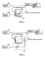
- the control logic shown in Fig. 2 is a compensation method wherein the override compensation pressure calculation section 34a uses set relief pressures Prel, set attachment flow rates Qatt described above, and a three-dimensional map 41 that is created beforehand based on the relationship between an override compensation pressure ⁇ P and these values Prel,Qatt.
- the pressure override characteristics that have been ascertained beforehand are formed into a three-dimensional map. Then, by inputting a set relief pressure Prel and a set attachment flow rate Qatt described above to the pressure override characteristics that have been formed into the three-dimensional map, an override compensation pressure ⁇ P for each solenoid-operated variable pressure relief valve 33 is calculated. Thereafter, the override compensation pressure ⁇ P is subtracted from the set relief pressure Prel so that the solenoid-operated variable pressure relief valve 33 is controlled based on the electric current value that corresponds to the adjusted set relief pressure (commanded pressure) resulting from the compensation of the pressure override characteristics.
- the control logic shown in Fig. 3 is a simple logic that can be employed in cases where linear approximation of pressure override characteristics with respect to relief valve passing flow rates is possible.
- This simple logic uses an override compensation pressure calculation section 34b that can be realized relatively easily without using a three-dimensional map 41 described above.
- the override compensation pressure calculation section 34b uses a two-dimensional map 42 that is created beforehand based on the relationship between a plurality of set relief pressures Prel that are respectively represented by electric current values A0-A7 and override pressures at a constant flow rate (flow rate-pressure gradient) resulting from linear approximation of pressure override characteristics with respect to relief valve passing flow rates at the respective set relief pressures Prel.
- the override compensation pressure calculation section 34b determines an override pressure at a constant flow rate (flow rate-pressure gradient).
- influence of the attachment flow rate Qatt is adjusted by multiplying the attachment flow rate Qatt by a gain G.
- An override compensation pressure ⁇ P at the attachment flow rate Qatt is calculated by multiplying the override pressure at a constant flow rate (flow rate-pressure gradient) by the aforementioned attachment flow rate G*Qatt by means of a multiplier 43 connected to the two-dimensional map 42. Then, the override compensation pressure ⁇ P is subtracted from the set relief pressure Prel so that the solenoid-operated variable pressure relief valve 33 is controlled by means of the electric current value corresponding to the adjusted set relief pressure (commanded pressure) that resulted from compensation of the pressure override characteristics.
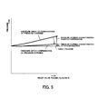
- Fig. 5 shows results of tests conducted to examine pressure override compensation. From the test results, it is evident that pressure override characteristics prior to compensation were drastically reduced and became close to a target pressure by the pressure override compensation as represented by commanded pressure shown in Fig. 4 . In other words, the invention is capable of drastically improving accuracy of relief pressure for a solenoid-operated variable pressure relief valve 33 with respect to target pressure.
- an override compensation pressure for a solenoid-operated variable pressure relief valve 33 is calculated by using an attachment flow rate Qatt, which is used for setting the flow rate of the hydraulic oil that is expected to flow into the attachment cylinder 15 of the attachment tool 14, and the commanded pump flow rate for controlling the capacity adjustment means 26 of the variable delivery pumps 21 are not used for calculation of the override compensation pressure.
- an override compensation pressure is calculated based on a commanded pump flow rate.
- an override compensation pressure would be calculated based on a pump command flow rate, which is the sum of a set attachment flow rate and an additional flow rate for tandem operation, which is required when operating the attachment simultaneously with another actuator.
- the hydraulic circuit for simultaneously operating the plurality of actuators by means of hydraulic fluid includes the controller 31 and the solenoid-operated variable pressure relief valves 33 that serve to control pressure in the lines 23 to the attachment cylinder 15, wherein the controller 31 is capable of outputting to each solenoid-operated variable pressure relief valve 33 a command signal related to the set relief pressures for the solenoid-operated variable pressure relief valve 33 of which pressure override characteristics have been compensated for based on input signals related to the set relief pressure and a relief valve passing flow rate. Therefore, the present invention is capable of improving accuracy of relief pressure with respect to a set relief pressure for a solenoid-operated variable pressure relief valve 33 that is provided for controlling working pressure of the attachment cylinder 15.
- exact override compensation can be performed by using the override compensation pressure calculation section 34a, which is provided with the three-dimensional map 41, as well as the subtraction section 35 for calculating an adjusted set relief pressure, which is the set relief pressure resulting from the pressure override compensation.
- override compensation can be easily performed by using the override compensation pressure calculation section 34b, which is provided with the two-dimensional map 42 created by linear approximation of the aforementioned pressure override characteristics with respect to relief valve passing flow rates, as well as the subtraction section 35 for calculating an adjusted set relief pressure, which is the set relief pressure resulting from the pressure override compensation.
- the pump flow rate limiting controller 27 is provided on the neg-con pressure line 25L and controls a pump flow rate based on the pump flow rate limiting value that is set by the monitor 29 and is assigned to the attachment that is going to be used; and the controller 31 uses the aforementioned pump flow rate limiting value for the pump flow rate limiting controller 27, i.e. the set attachment flow rate, as the estimated value representing the flow rate passing through a solenoid-operated variable pressure relief valve 33. Therefore, flow rate passing through the solenoid-operated variable pressure relief valve 33 can be limited easily by using a pump flow rate limiting value that is set by the monitor 29.
- the present invention provides a work machine M of which accuracy of a relief pressure with respect to a set relief pressure for each respective solenoid-operated variable pressure relief valve 33 that serves to control working pressure of the attachment cylinder 15 for operating the attachment tool 14 attached to the distal end of the work equipment 13 can be improved by compensating for pressure override characteristics of the solenoid-operated variable pressure relief valves 33.
- the present invention is applicable in any industry that is involved in production and sales of hydraulic circuit control devices and work machines.
Landscapes
- Engineering & Computer Science (AREA)
- General Engineering & Computer Science (AREA)
- Mining & Mineral Resources (AREA)
- Civil Engineering (AREA)
- Structural Engineering (AREA)
- Physics & Mathematics (AREA)
- Fluid Mechanics (AREA)
- Mechanical Engineering (AREA)
- Fluid-Pressure Circuits (AREA)
- Operation Control Of Excavators (AREA)
- Component Parts Of Construction Machinery (AREA)
- Control Of Fluid Pressure (AREA)
Abstract
Description
- The present invention relates to a hydraulic circuit control device provided with a solenoid-operated variable pressure relief valve. The present invention further relates to a work machine that is provided with such a control device.
- As shown in
Fig. 8 , a tool control system used in a hydraulic circuit of a work machine employs solenoid-operated variablepressure relief valves 5 that are provided onexternal output lines 4 through which hydraulic oil discharged fromvariable delivery pumps 1 is controlled by acontrol valve 2 and fed to anattachment tool 3. Thus provided, the solenoid-operated variablepressure relief valves 5 serve as external relief valves. As shown inFig. 9 , each solenoid-operated variablepressure relief valve 5 is designed to set relief pressure in response to a command electric current value A0-A7. Therefore, as shown inFig. 8 , the tool control system is designed so that amachine controller 7 outputs to each solenoid-operated variablepressure relief valve 5 an electric current value selected from among the command electric current values A0-A7 based on a relief pressure that has been set by means of amonitor 6 installed in the cab of a construction machine or the like. Thus, the set relief pressure for each solenoid-operated variablepressure relief valve 5 can be changed easily without the necessity of manually turning a screw that is attached to the relief valve. - With the conventional tool control system, however, once a relief pressure is set based on a given electric current value, the relief valve is controlled by the constant current that corresponds to the set relief pressure. Therefore, as shown in
Fig. 9 , when the flow rate of the hydraulic oil passing through the relief valve increases, there arise pressure override characteristics, in other words an increase in pressure caused by valve resistance, resulting in a difference between the set relief pressure and the actual pressure. - On the other hand, examples of hydraulic control of such apparatuses as a hydraulic press include a pressure control shown in
Fig. 10 , wherein acontrol device 9 compensates for pressure override characteristics of a solenoid-operated variablepressure relief valve 10 based on a commanded pump flow rate represented by a signal that transmits a command to control the flow rate of hydraulic oil discharged from a variable delivery pump 8 (e. g. see PTL 1). -
- PTL 1: Japanese Laid-open Patent Publication No.
5-146900 p 2, andFig. 1 ) - The technology for pressure override compensation described in
PTL 1 is for compensating for pressure override characteristics of a solenoid-operated variable pressure relief valve based on a commanded pump flow rate. Therefore, when employed in a machine that is provided with a plurality of hydraulic actuators, the technology is incapable of compensating for pressure override of relief pressure for a specific hydraulic actuator with high accuracy. - In order to solve the above problem, an object of the invention is to improve accuracy of relief pressure with respect to a set relief pressure of a solenoid-operated variable pressure relief valve that is provided for controlling pressure of a specific hydraulic actuator.
-
Claim 1 of the present invention relates to a hydraulic circuit control device for controlling a hydraulic circuit that serves to operate a hydraulic actuator by means of hydraulic fluid. The hydraulic circuit control device includes a solenoid-operated variable pressure relief valve and a control means. The solenoid-operated variable pressure relief valve controls pressure of the hydraulic fluid fed to the aforementioned hydraulic actuator at a set relief pressure that can be electrically commanded. Based on input signals related to the set relief pressure for and a relief valve passing flow rate of the aforementioned solenoid-operated variable pressure relief valve, the control means compensates for pressure override characteristics of the solenoid-operated variable pressure relief valve and outputs to the solenoid-operated variable pressure relief valve a command signal related to an adjusted set relief pressure resulting from the compensation of the pressure override characteristics. - According to
claim 2 of the present invention, the control means of the hydraulic circuit control device according toclaim 1 of the present invention includes an override compensation pressure calculation section and a subtraction section. The override compensation pressure calculation section has a function of calculating an override compensation pressure for compensating for the aforementioned pressure override characteristics, the override compensation pressure calculation section performing the calculation by inputting the set relief pressure and the relief valve passing flow rate to a three-dimensional map that is created beforehand based on the relationship of the set relief pressure, the relief valve passing flow rate, and the override compensation pressure. By subtracting from the aforementioned set relief pressure the override compensation pressure calculated by the override compensation pressure calculation section, the subtraction section calculates an adjusted set relief pressure resulting from the compensation of pressure override characteristics. - According to
claim 3 of the present invention, the control means of the hydraulic circuit control device according toclaim 1 of the present invention includes an override compensation pressure calculation section and a subtraction section. The override compensation pressure calculation section has a function of calculating an override compensation pressure by determining characteristics of a relationship between a relief valve passing flow rate and an override pressure by inputting a set relief pressure to a two-dimensional map that is created beforehand based on the relationship between a plurality of set relief pressures and override pressures at a constant flow rate resulting from linear approximation of the pressure override characteristics with respect to the relief valve passing flow rates at the respective set relief pressures, and multiplying the determined characteristics of the relationship between the relief valve passing flow rate and the override pressure by the relief valve passing flow rate. By subtracting from the aforementioned set relief pressure the override compensation pressure calculated by the override compensation pressure calculation section, the subtraction section calculates an adjusted set relief pressure resulting from the compensation of pressure override characteristics. - According to
claim 4 of the present invention, the hydraulic circuit control device according to any one of claims fromclaim 1 to claim 3 of the present invention is provided with a negative flow control pressure line, a pump flow rate limiting controller, and an input means. The negative flow control pressure line guides negative flow control pressure from a center bypass line of a control valve that serves to control a plurality of hydraulic actuators to a capacity adjustment means of a variable delivery pump. The pump flow rate limiting controller is provided on the negative flow control pressure line so as to limit pump flow rate based on a pump flow rate limiting value that is assigned to a specific actuator. The pump flow rate limiting value to be output to the pump flow rate limiting controller is set in the input means. The control means uses, as an estimated value representing a flow rate of the hydraulic fluid passing through a solenoid-operated variable pressure relief valve that controls the aforementioned specific actuator, the pump flow rate limiting value set in the input means. -
Claim 5 of the present invention relates to a work machine including a machine body; a work equipment mounted on the machine body and adapted to be operated by a plurality of hydraulic actuators; an attachment tool attached to the distal end of the work equipment; and a hydraulic circuit control device according to any one of claims fromclaim 1 to claim 4 of the present invention and provided for the hydraulic actuator for operating the attachment tool. - According to
claim 1 of the present invention, based on input signals related to a set relief pressure for and a relief valve passing flow rate of a solenoid-operated variable pressure relief valve for controlling a line to a hydraulic actuator at the set relief pressure, the control means compensates for pressure override characteristics of the solenoid-operated variable pressure relief valve and outputs to the solenoid-operated variable pressure relief valve a command signal related to the adjusted set relief pressure. Therefore, the present invention is capable of improving accuracy of relief pressure with respect to a set relief pressure for a solenoid-operated variable pressure relief valve that is provided for controlling pressure of a specific hydraulic actuator. - According to
claim 2 of the present invention, exact override compensation can be performed by using the override compensation pressure calculation section, which is provided with the three-dimensional map, as well as the subtraction section for calculating an adjusted set relief pressure, which is an adjusted set relief pressure resulting from pressure override compensation. - According to
claim 3 of the present invention, override compensation can be easily performed by using the override compensation pressure calculation section, which is provided with the two-dimensional map created by linear approximation of the aforementioned pressure override characteristics with respect to the relief valve passing flow rates, as well as the subtraction section for calculating an adjusted set relief pressure resulting from the pressure override compensation. - According to
claim 4 of the present invention, the control means uses, as an estimated value representing a flow rate of the hydraulic fluid passing through a solenoid-operated variable pressure relief valve for that controls the aforementioned specific actuator, the pump flow rate limiting value set in the input means and to be output to the pump flow rate limiting controller, which is provided on the negative flow control pressure line so as to limit pump flow rate based on a pump flow rate limiting value that is assigned to the specific actuator. Therefore, a flow rate of the hydraulic fluid passing through the solenoid-operated variable pressure relief valve can be estimated easily by using a pump flow rate limiting value set in the input means. - According to
claim 5 thereof, the present invention is capable of providing a work machine of which accuracy of the relief pressure with respect to a set relief pressure for a solenoid-operated variable pressure relief valve that serves to control pressure of a specific actuator for operating the attachment tool attached to the distal end of the work equipment can be improved by compensating for pressure override characteristics of the solenoid-operated variable pressure relief valve. -
-
Fig. 1 is a circuit configuration diagram showing an embodiment of a hydraulic circuit control device according to the present invention. -
Fig. 2 is a block diagram showing a first example of the compensation logic of the aforementioned control device. -
Fig. 3 is a block diagram showing a second example of the compensation logic of the control device. -
Fig. 4 is a characteristic diagram for explaining pressure override characteristics of a solenoid-operated variable pressure relief valve of the control device and the principle of compensation of the pressure override characteristics. -
Fig. 5 is a characteristic diagram showing an example of compensation of pressure override characteristics of the solenoid-operated variable pressure relief valve of the control device. -
Fig. 6 is a side view of a work machine equipped with the control device. -
Fig. 7 is a circuit diagram illustrating the circuit configuration of the control valve shown inFig 1 . -
Fig. 8 is a configuration diagram showing a tool control system used in a conventional hydraulic circuit of a work machine. -
Fig. 9 is a characteristic diagram for explaining pressure override characteristics of a solenoid-operated variable pressure relief valve. -
Fig. 10 is a circuit diagram showing a conventional pressure override compensation system. - Next, the present invention is explained in detail hereunder, referring to an embodiment thereof shown in
Figs. 1 to 7 . -
Fig. 6 illustrates a hydraulic excavator-type work machine M, of which amachine body 11 has alower structure 11a and anupper structure 11b. Theupper structure 11b is rotatably mounted on thelower structure 11a. Acab 12 and awork equipment 13 are mounted on themachine body 11, and anattachment tool 14 is removably attached to the distal end of thework equipment 13. - Examples of attachment tools of this type include various tools, such as a hydraulic breaker (a hammer), that use a single acting circuit, and also tools, such as a grapple or a crusher, that use a double acting circuit. Examples of tools using a double acting circuit include an
attachment tool 14 shown inFig. 6 , wherein a pair ofgripping blades 16 or the like are opened and closed by anattachment cylinder 15, which is a hydraulic actuator and serves as a specific actuator. - The
work equipment 13 includes a boom 13bm and a stick 13st. The base end of the boom 13bm is supported on theupper structure 11b by a shaft so that the boom 13bm is capable of pivoting vertically. The stick 13st is pivotally supported at the distal end of the boom 13bm by a shaft. Theaforementioned attachment tool 14 is pivotally supported at the distal end of the stick 13st by a shaft. The boom 13bm, the stick 13st, and theattachment tool 14 are adapted to be pivoted by boom cylinders 13bmc, stick cylinders 13stc, and a bucket cylinder 13bkc, respectively. Theattachment tool 14 is adapted to be opened and closed by theattachment cylinder 15. - The work machine M shown in
Fig. 6 described above is equipped with a hydraulic circuit control device A shown inFig. 1 . The hydraulic fluid controlled by the control device A is hydraulic oil. -
Fig. 7 illustrates, in the form of a circuit diagram, a control valve shown inFig. 1. Figs. 1 and7 schematically illustrate the hydraulic circuit control device A, wherein discharge openings of variable delivery pumps 21, which are mounted on themachine body 11, are connected to thecontrol valve 22 for controlling hydraulic oil discharged from thepumps 21. The direction and flow rate of the hydraulic oil is controlled by a plurality of actuator controlling spools 22sp, which form thecontrol valve 22.Output lines 23 for the hydraulic oil are connected to various hydraulic actuators of the hydraulic excavator, such as right and left travel motors, a swing motor, the boom cylinders 13bmc, the stick cylinders 13stc, the bucket cylinder 13bkc, and theattachment cylinder 15. - In order to draw out negative flow control pressure (hereinafter referred to as neg-con pressure), a
center bypass line 24 in thecontrol valve 22 is provided with arelief valve 25R, an orifice 25o, and a neg-con pressure line 25L. Eachvariable delivery pump 21 is provided with a capacity adjustment means 26, which is controlled by means of neg-con pressure drawn out through the negative flow control pressure line, i.e. the neg-con pressure line 25L. The control device A performs control in such a way that the closer each actuator controlling spool 22sp of thecontrol valve 22 is to the neutral position for stopping the corresponding actuator, the greater the neg-con pressure, causing the capacity adjustment means 26 to reduce the discharge rate of thevariable delivery pump 21. This is the way the flow rate limiting system using neg-con pressure is structured. - Provided on the neg-
con pressure line 25L is a pump flowrate limiting controller 27 for limiting pump flow rate based on a pump flow rate limiting value that is assigned to the degree of movement of theattachment cylinder 15, which serves as a specific actuator. - The pump flow
rate limiting controller 27 is provided withshuttle valves 28a, which are provided on the neg-con pressure line 25L, and solenoid-operatedproportional valves 28b. The solenoid-operatedproportional valves 28b are connected to the neg-con pressure line 25L via theshuttle valves 28a, and are capable of controlling discharge rates of the respective variable delivery pumps 21 by using the neg-con pressure line 25L. - To be more specific, the configuration as above makes it possible to set pump discharge rates by way of a
monitor 29, which is installed in thecab 12 and serves as an input means. By means of acontroller 31 of the machine body of the hydraulic excavator (hereinafter referred to simply as the controller 31), which is connected to themonitor 29 and serves as a control means, a pump discharge rate set value input from themonitor 29 is converted to an appropriate electric current value, and the electric current value is input from the control means 31 to the solenoid of the corresponding solenoid-operatedproportional valve 28b. A secondary pressure resulting from reducing a primary pressure P by the solenoid-operatedproportional valve 28b in response to the aforementioned electric current value is applied to the capacity adjustment means 26 through the correspondingshuttle valve 28a, thereby controlling the discharge rate of thevariable delivery pump 21. - A solenoid-operated variable
pressure relief valve 33 is provided between atank 32 and each one of theoutput lines 23 for the hydraulic oil, which are connected from thecontrol valve 22 to the hydraulic actuators. The solenoid-operated variablepressure relief valves 33 serve to control the pressure of the fluid in theoutput lines 23 at respective set relief pressures that can be electrically commanded by way of themonitor 29 installed in thecab 12. - Each solenoid-operated variable
pressure relief valve 33 is a pressure control valve for controlling the pressure in theoutput line 23 at a set relief pressure corresponding to a command electric current value output from thecontroller 31 to a solenoid 33sol, based on a value selected by an operator in thecab 12 by using themonitor 29. -
Fig. 4 shows characteristics of a solenoid-operated variablepressure relief valve 33 and illustrates a case where the smaller the command electric current value (A0<A<1...<A6<A7), the higher the set relief pressure. Furthermore, the further the flow rate of the hydraulic oil passing through the solenoid-operated variablepressure relief valve 33 increases, the more prominent the pressure override characteristics become. In addition, pressure override characteristics change also depending on the set relief pressure (command electric current value A0...A7). - From these facts, it is evident that, in order to compensate for pressure override characteristics, it is necessary to input the flow rate of the hydraulic oil passing through the relief valve, in other words the relief valve passing flow rate, at the moment when compensation is performed, as well as the set relief pressure.
- As shown in
Fig. 1 , when controlling the pressure of theattachment cylinder 15 at a set relief pressure by means of the solenoid-operated variablepressure relief valves 33, two types of signals for each solenoid-operated variablepressure relief valve 33, i.e. a set relief pressure Prel and a set attachment flow rate Qatt, which is a relief valve passing flow rate, are input from themonitor 29 to thecontroller 31. By compensating for the unadjusted set relief pressure shown by dotted line inFig. 4 , i.e. the target pressure, to the set relief pressure shown by solid line inFig. 4 , i.e. the commanded pressure, the actual pressure (for example the pressure shown by the command electric current value A3) is brought close to the set relief pressure shown by dotted line, i.e. the target pressure. - For this purpose, as shown in
Fig. 1 , thecontroller 31 includes an override compensationpressure calculation section 34, asubtraction section 35, and aconverter 36. The override compensationpressure calculation section 34 calculates an override compensation pressure ΔP from a set relief pressure Prel and a set attachment flow rate Qatt. Thesubtraction section 35 calculates a set relief pressure that results from compensation of pressure override and serves as a commanded pressure, by subtracting the override compensation pressure ΔP, which corresponds to the set attachment flow rate and has been calculated by the override compensationpressure calculation section 34, from the set relief pressure Prel. The commanded pressure is then converted to an electric current value by theconverter 36. - The
controller 31 includes aconverter section 37, which converts pump discharge rate set values input from themonitor 29 to appropriate electric current values, and outputs the electric current values to the solenoids of the respective solenoid-operatedproportional valve 28b. Each solenoid-operatedproportional valve 28b produces a secondary pressure by reducing a primary pressure P in accordance with the electric current value input from thecontroller 31, and applies the secondary pressure to the capacity adjustment means 26 of thevariable delivery pump 21 through theshuttle valve 28a, thereby controlling discharge rate of thevariable delivery pump 21. - As described above, in order to solve the problem of pressure override characteristics of a solenoid-operated variable
pressure relief valve 33 causing a difference between a set relief pressure and an actual pressure, the present invention provides a structure of a system that is capable of simultaneously performing compensation of pressure override characteristics in accordance with a relief valve passing flow rate and compensation of pressure override characteristics in accordance with the set relief pressure. - Furthermore, in order to solve the above problem, it is desirable to perform feedback control of override pressure, i.e. error pressure resulting from pressure override characteristics, and relief flow rate. However, it is difficult for a circuit that includes a solenoid-operated variable
pressure relief valve 33 to be provided with a flow meter and a pressure gauge. Therefore, the present invention employs feed forward control using values described below, i.e. estimated values and values prepared beforehand, as override pressures and relief valve passing flow rates of the solenoid-operated variablepressure relief valves 33. - Next, how compensation is performed is explained in concrete terms.
- First of all, as shown in
Fig. 4 , pressure override characteristics of the solenoid-operated variablepressure relief valves 33 provided for theattachment tool 14 are ascertained based on designed values, benchmark data, and data on the actual machine. - Next, the relief valve passing flow rates of the fluid passing through the solenoid-operated variable
pressure relief valves 33 are estimated. The estimated relief valve passing flow rates are used based on the assumption that the set attachment flow rates Qatt for controlling the attachment tool are regarded as control input related to the relief valve passing flow rates. - In other words, when operating the
attachment cylinder 15 of anattachment tool 14, pump flow rate limiting control is normally performed to limit pump flow rates appropriate for theattachment tool 14 mounted on thework equipment 13 by using the solenoid-operatedproportional valves 28b, which serve to control the neg-con pressure, so as to prevent hydraulic oil from flowing to theattachment cylinder 15 at an excessively great flow rate. The pump flow rate limiting values assigned to therespective attachment tools 14 are set beforehand by using themonitor 29. The pump flow rate limiting values set by themonitor 29 are used as the aforementioned set attachment flow rates Qatt for controlling the attachment tools, in other words as estimated values of flow rates of the hydraulic oil passing through the solenoid-operated variablepressure relief valves 33. - Next, either the control logic shown in
Fig. 2 or the control logic shown inFig. 3 is applied. - The control logic shown in
Fig. 2 is a compensation method wherein the override compensationpressure calculation section 34a uses set relief pressures Prel, set attachment flow rates Qatt described above, and a three-dimensional map 41 that is created beforehand based on the relationship between an override compensation pressure ΔP and these values Prel,Qatt. - As described above, the pressure override characteristics that have been ascertained beforehand are formed into a three-dimensional map. Then, by inputting a set relief pressure Prel and a set attachment flow rate Qatt described above to the pressure override characteristics that have been formed into the three-dimensional map, an override compensation pressure ΔP for each solenoid-operated variable
pressure relief valve 33 is calculated. Thereafter, the override compensation pressure ΔP is subtracted from the set relief pressure Prel so that the solenoid-operated variablepressure relief valve 33 is controlled based on the electric current value that corresponds to the adjusted set relief pressure (commanded pressure) resulting from the compensation of the pressure override characteristics. - The control logic shown in
Fig. 3 is a simple logic that can be employed in cases where linear approximation of pressure override characteristics with respect to relief valve passing flow rates is possible. This simple logic uses an override compensationpressure calculation section 34b that can be realized relatively easily without using a three-dimensional map 41 described above. - As shown in
Fig. 4 , the override compensationpressure calculation section 34b uses a two-dimensional map 42 that is created beforehand based on the relationship between a plurality of set relief pressures Prel that are respectively represented by electric current values A0-A7 and override pressures at a constant flow rate (flow rate-pressure gradient) resulting from linear approximation of pressure override characteristics with respect to relief valve passing flow rates at the respective set relief pressures Prel. By inputting a set relief pressure Prel to the two-dimensional map 42, the override compensationpressure calculation section 34b determines an override pressure at a constant flow rate (flow rate-pressure gradient). - Furthermore, influence of the attachment flow rate Qatt is adjusted by multiplying the attachment flow rate Qatt by a gain G. An override compensation pressure ΔP at the attachment flow rate Qatt is calculated by multiplying the override pressure at a constant flow rate (flow rate-pressure gradient) by the aforementioned attachment flow rate G*Qatt by means of a
multiplier 43 connected to the two-dimensional map 42. Then, the override compensation pressure ΔP is subtracted from the set relief pressure Prel so that the solenoid-operated variablepressure relief valve 33 is controlled by means of the electric current value corresponding to the adjusted set relief pressure (commanded pressure) that resulted from compensation of the pressure override characteristics. -
Fig. 5 shows results of tests conducted to examine pressure override compensation. From the test results, it is evident that pressure override characteristics prior to compensation were drastically reduced and became close to a target pressure by the pressure override compensation as represented by commanded pressure shown inFig. 4 . In other words, the invention is capable of drastically improving accuracy of relief pressure for a solenoid-operated variablepressure relief valve 33 with respect to target pressure. - As shown in
Fig. 7 , according to the method of the present invention, an override compensation pressure for a solenoid-operated variablepressure relief valve 33 is calculated by using an attachment flow rate Qatt, which is used for setting the flow rate of the hydraulic oil that is expected to flow into theattachment cylinder 15 of theattachment tool 14, and the commanded pump flow rate for controlling the capacity adjustment means 26 of the variable delivery pumps 21 are not used for calculation of the override compensation pressure. - On the other hand, according to conventional hydraulic control, such as the hydraulic press control shown in
Fig. 10 , an override compensation pressure is calculated based on a commanded pump flow rate. However, should this method be applied without adjustment to a flow limiting system that uses neg-con pressure, an override compensation pressure would be calculated based on a pump command flow rate, which is the sum of a set attachment flow rate and an additional flow rate for tandem operation, which is required when operating the attachment simultaneously with another actuator. - As described above, the hydraulic circuit for simultaneously operating the plurality of actuators by means of hydraulic fluid includes the
controller 31 and the solenoid-operated variablepressure relief valves 33 that serve to control pressure in thelines 23 to theattachment cylinder 15, wherein thecontroller 31 is capable of outputting to each solenoid-operated variable pressure relief valve 33 a command signal related to the set relief pressures for the solenoid-operated variablepressure relief valve 33 of which pressure override characteristics have been compensated for based on input signals related to the set relief pressure and a relief valve passing flow rate. Therefore, the present invention is capable of improving accuracy of relief pressure with respect to a set relief pressure for a solenoid-operated variablepressure relief valve 33 that is provided for controlling working pressure of theattachment cylinder 15. - Furthermore, exact override compensation can be performed by using the override compensation
pressure calculation section 34a, which is provided with the three-dimensional map 41, as well as thesubtraction section 35 for calculating an adjusted set relief pressure, which is the set relief pressure resulting from the pressure override compensation. - Furthermore, override compensation can be easily performed by using the override compensation
pressure calculation section 34b, which is provided with the two-dimensional map 42 created by linear approximation of the aforementioned pressure override characteristics with respect to relief valve passing flow rates, as well as thesubtraction section 35 for calculating an adjusted set relief pressure, which is the set relief pressure resulting from the pressure override compensation. - Furthermore, the pump flow
rate limiting controller 27 is provided on the neg-con pressure line 25L and controls a pump flow rate based on the pump flow rate limiting value that is set by themonitor 29 and is assigned to the attachment that is going to be used; and thecontroller 31 uses the aforementioned pump flow rate limiting value for the pump flowrate limiting controller 27, i.e. the set attachment flow rate, as the estimated value representing the flow rate passing through a solenoid-operated variablepressure relief valve 33. Therefore, flow rate passing through the solenoid-operated variablepressure relief valve 33 can be limited easily by using a pump flow rate limiting value that is set by themonitor 29. - Furthermore, the present invention provides a work machine M of which accuracy of a relief pressure with respect to a set relief pressure for each respective solenoid-operated variable
pressure relief valve 33 that serves to control working pressure of theattachment cylinder 15 for operating theattachment tool 14 attached to the distal end of thework equipment 13 can be improved by compensating for pressure override characteristics of the solenoid-operated variablepressure relief valves 33. - The present invention is applicable in any industry that is involved in production and sales of hydraulic circuit control devices and work machines.
-
- M
- work machine
- A
- hydraulic circuit control device
- 11
- machine body
- 13bmc,13stc,13bkc
- hydraulic actuator
- 14
- attachment tool
- 15
- attachment cylinder as a hydraulic actuator that is a specific actuator
- 21
- variable delivery pump
- 22
- control valve
- 23
- line
- 24
- center bypass line
- 25L
- negative flow control pressure line
- 26
- capacity adjustment means
- 27
- pump flow rate limiting controller
- 29
- monitor as an input means
- 31
- controller as a control means
- 33
- solenoid-operated variable pressure relief valve
- 34a,34b
- override compensation pressure calculation section
- 35
- subtraction section
- 41
- three-dimensional map
- 42
- two-dimensional map
Claims (5)
- A hydraulic circuit control device for controlling a hydraulic circuit that serves to operate a hydraulic actuator by means of hydraulic fluid, the hydraulic circuit control device comprising:a solenoid-operated variable pressure relief valve adapted to control pressure of the hydraulic fluid fed to the hydraulic actuator at a set relief pressure that can be electrically commanded; anda control means adapted to compensate for pressure override characteristics of the solenoid-operated variable pressure relief valve based on input signals related to the set relief pressure for and a relief valve passing flow rate of the solenoid-operated variable pressure relief valve, and output to the solenoid-operated variable pressure relief valve a command signal related to an adjusted set relief pressure that results from the compensation of the pressure override characteristics.
- A hydraulic circuit control device as claimed in claim 1, wherein the control means comprises:an override compensation pressure calculation section having a function of calculating an override compensation pressure for compensating for the pressure override characteristics, the override compensation pressure calculation section performing the calculation by inputting the set relief pressure and the relief valve passing flow rate to a three-dimensional map that is created beforehand based on the relationship of the set relief pressure, the relief valve passing flow rate, and the override compensation pressure; anda subtraction section for calculating an adjusted set relief pressure resulting from the compensation of pressure override characteristics, the subtraction section performing the calculation by subtracting from the set relief pressure the override compensation pressure calculated by the override compensation pressure calculation section.
- A hydraulic circuit control device as claimed in claim 1, wherein the control means comprises:an override compensation pressure calculation section having a function of calculating an override compensation pressure by:determining characteristics of a relationship between a relief valve passing flow rate and an override pressure by inputting a set relief pressure to a two-dimensional map that is created beforehand based on a relationship between a plurality of set relief pressures and override pressures at a constant flow rate resulting from linear approximation of the pressure override characteristics with respect to the relief valve passing flow rates at the respective set relief pressures, andmultiplying the determined characteristics of the relationship between the relief valve passing flow rate and the override pressure by the relief valve passing flow rate; anda subtraction section for calculating an adjusted set relief pressure resulting from the compensation of pressure override characteristics, the subtraction section performing the calculation by subtracting from the set relief pressure the override compensation pressure calculated by the override compensation pressure calculation section.
- A hydraulic circuit control device as claimed in any one of the claims from claim 1 to claim 3, wherein:the hydraulic circuit control device includes:a negative flow control pressure line for guiding negative flow control pressure from a center bypass line of a control valve that serves to control a plurality of hydraulic actuators to a capacity adjustment means of a variable delivery pump,a pump flow rate limiting controller that is provided on the negative flow control pressure line and serves to limit pump flow rate based on a pump flow rate limiting value that is assigned to a specific actuator, andan input means in which a pump flow rate limiting value to be output to the pump flow rate limiting controller is set; andthe control means uses, as an estimated value representing a flow rate of the hydraulic fluid passing through a solenoid-operated variable pressure relief valve that controls the specific actuator, the pump flow rate limiting value that is set in the input means.
- A work machine comprising:a machine body;a work equipment mounted on the machine body and adapted to be operated by a plurality of hydraulic actuators;an attachment tool attached to the distal end of the work equipment; anda hydraulic circuit control device as claimed in any one of the claims from claim 1 to claim 4 and provided for a hydraulic actuator for operating the attachment tool.
Applications Claiming Priority (2)
| Application Number | Priority Date | Filing Date | Title |
|---|---|---|---|
| JP2010292878A JP5500651B2 (en) | 2010-12-28 | 2010-12-28 | Fluid pressure circuit control device and work machine |
| PCT/JP2011/080312 WO2012091059A1 (en) | 2010-12-28 | 2011-12-27 | Fluid pressure circuit control apparatus and working machine |
Publications (3)
| Publication Number | Publication Date |
|---|---|
| EP2660476A1 true EP2660476A1 (en) | 2013-11-06 |
| EP2660476A4 EP2660476A4 (en) | 2013-12-25 |
| EP2660476B1 EP2660476B1 (en) | 2016-12-14 |
Family
ID=46383150
Family Applications (1)
| Application Number | Title | Priority Date | Filing Date |
|---|---|---|---|
| EP11852327.3A Not-in-force EP2660476B1 (en) | 2010-12-28 | 2011-12-27 | Fluid pressure circuit control apparatus and working machine |
Country Status (5)
| Country | Link |
|---|---|
| US (1) | US9103095B2 (en) |
| EP (1) | EP2660476B1 (en) |
| JP (1) | JP5500651B2 (en) |
| CN (1) | CN102893036B (en) |
| WO (1) | WO2012091059A1 (en) |
Families Citing this family (16)
| Publication number | Priority date | Publication date | Assignee | Title |
|---|---|---|---|---|
| JP6138497B2 (en) * | 2013-01-21 | 2017-05-31 | 株式会社技研製作所 | Hydraulic drive system |
| CA2849383C (en) * | 2013-08-20 | 2016-06-07 | Yasunori Kimura | Construction machine controller |
| JP6347936B2 (en) * | 2013-10-23 | 2018-06-27 | 住友建機株式会社 | Work machine |
| JP6509899B2 (en) * | 2014-11-10 | 2019-05-08 | 住友建機株式会社 | Work machine |
| CN108026713B (en) * | 2015-09-16 | 2021-03-09 | 卡特彼勒Sarl | Hydraulic pump control system for hydraulic working machine |
| US10487855B2 (en) | 2016-09-29 | 2019-11-26 | Deere & Company | Electro-hydraulic system with negative flow control |
| CN106759621B (en) * | 2017-01-04 | 2018-12-14 | 浙江高宇液压机电有限公司 | Load-sensitive formula loading machine determines variable delivery hydraulic system |
| US10975893B2 (en) * | 2017-10-03 | 2021-04-13 | Kubota Corporation | Hydraulic system for working machine |
| JP6860521B2 (en) * | 2018-03-30 | 2021-04-14 | 日立建機株式会社 | Construction machinery |
| JP2020023793A (en) * | 2018-08-06 | 2020-02-13 | 日立建機株式会社 | Construction machine |
| CN109914518B (en) * | 2019-03-13 | 2022-04-01 | 徐州徐工矿业机械有限公司 | Device for improving dynamic matching performance of power of large excavator |
| CN109826273A (en) * | 2019-03-29 | 2019-05-31 | 三一重机有限公司 | Hydraulic pilot control system and excavator |
| CN110747927A (en) * | 2019-10-29 | 2020-02-04 | 三一重机有限公司 | Slewing device and excavator |
| JP7666079B2 (en) * | 2021-03-31 | 2025-04-22 | 住友重機械工業株式会社 | Hydraulic circuits for excavators and other work machines |
| WO2023025412A1 (en) | 2021-08-26 | 2023-03-02 | Caterpillar Sarl | Hydraulic control system and setting method and calibration method of target engine torque during relief in hydraulic control system |
| JP2024104396A (en) | 2023-01-24 | 2024-08-05 | キャタピラー エス エー アール エル | Relief pressure adjustment system |
Family Cites Families (10)
| Publication number | Priority date | Publication date | Assignee | Title |
|---|---|---|---|---|
| US4586025A (en) | 1985-10-04 | 1986-04-29 | Tektronix, Inc. | Error tolerant thermometer-to-binary encoder |
| JPH06240Y2 (en) * | 1985-11-20 | 1994-01-05 | 福井機械株式会社 | Pressure adjustment device for hydraulic die cushion device |
| JPH0813483B2 (en) | 1988-08-29 | 1996-02-14 | 株式会社名機製作所 | Injection pressure control method for injection molding machine |
| JP2900194B2 (en) * | 1991-01-22 | 1999-06-02 | 富士重工業株式会社 | Pressure control device for continuously variable transmission for vehicles |
| JP3325909B2 (en) | 1991-11-27 | 2002-09-17 | 川崎油工株式会社 | Pressure control method using an electromagnetic proportional pressure control valve |
| EP0795690B1 (en) * | 1995-07-10 | 2001-12-05 | Hitachi Construction Machinery Co., Ltd. | Hydraulic driving device |
| JP2003048016A (en) | 2001-08-02 | 2003-02-18 | Ube Machinery Corporation Ltd | Extruding pressure control system |
| US6813551B2 (en) | 2002-02-04 | 2004-11-02 | Toyota Jidosha Kabushiki Kaisha | Control apparatus for continuously variable transmission |
| JP4151597B2 (en) | 2004-03-31 | 2008-09-17 | コベルコ建機株式会社 | Hydraulic control circuit and construction machinery |
| JP2010236607A (en) * | 2009-03-31 | 2010-10-21 | Caterpillar Sarl | Hydraulic control circuit in construction machine |
-
2010
- 2010-12-28 JP JP2010292878A patent/JP5500651B2/en active Active
-
2011
- 2011-12-27 WO PCT/JP2011/080312 patent/WO2012091059A1/en not_active Ceased
- 2011-12-27 CN CN201180023233.8A patent/CN102893036B/en not_active Expired - Fee Related
- 2011-12-27 EP EP11852327.3A patent/EP2660476B1/en not_active Not-in-force
- 2011-12-27 US US13/502,166 patent/US9103095B2/en active Active
Also Published As
| Publication number | Publication date |
|---|---|
| US20120260646A1 (en) | 2012-10-18 |
| CN102893036A (en) | 2013-01-23 |
| EP2660476A4 (en) | 2013-12-25 |
| CN102893036B (en) | 2016-08-03 |
| WO2012091059A1 (en) | 2012-07-05 |
| JP5500651B2 (en) | 2014-05-21 |
| US9103095B2 (en) | 2015-08-11 |
| JP2012141705A (en) | 2012-07-26 |
| EP2660476B1 (en) | 2016-12-14 |
Similar Documents
| Publication | Publication Date | Title |
|---|---|---|
| EP2660476A1 (en) | Fluid pressure circuit control apparatus and working machine | |
| EP2947332B1 (en) | Device for recovering pressurized oil energy from work machine | |
| US9624647B2 (en) | Slewing-type working machine | |
| KR101693129B1 (en) | Work machine | |
| KR101918434B1 (en) | Hydraulic control equipment for construction machinery | |
| JP5965502B1 (en) | Hydraulic drive system for construction machinery | |
| US10400426B2 (en) | Hydraulic control system for construction machine | |
| EP2677180B1 (en) | Hydraulic drive device of a working machine | |
| KR102564414B1 (en) | Travel contorl system for construction machinery and travel control method for construction machinery | |
| KR20180033266A (en) | Working machine | |
| US10309079B2 (en) | Hydraulic control system for work machine | |
| JP7071339B2 (en) | Construction machine control system and construction machine control method | |
| CN110603384A (en) | Hydraulic drive device for construction machine | |
| EP3795844B1 (en) | Construction machine | |
| WO2016157531A1 (en) | Hydraulic control device for operating machine | |
| KR102422683B1 (en) | construction machinery | |
| JP7314404B2 (en) | working machine | |
| EP4212739A1 (en) | Hydraulic drive system | |
| US11142888B2 (en) | Hydraulic machine | |
| JP6901441B2 (en) | Hydraulic drive | |
| JP2012007656A (en) | Turning hydraulic control device for working machine | |
| JP6290709B2 (en) | Hydraulic drive | |
| JPH03138469A (en) | Load sensing type hydraulic driving device |
Legal Events
| Date | Code | Title | Description |
|---|---|---|---|
| PUAI | Public reference made under article 153(3) epc to a published international application that has entered the european phase |
Free format text: ORIGINAL CODE: 0009012 |
|
| 17P | Request for examination filed |
Effective date: 20130725 |
|
| AK | Designated contracting states |
Kind code of ref document: A1 Designated state(s): AL AT BE BG CH CY CZ DE DK EE ES FI FR GB GR HR HU IE IS IT LI LT LU LV MC MK MT NL NO PL PT RO RS SE SI SK SM TR |
|
| A4 | Supplementary search report drawn up and despatched |
Effective date: 20131125 |
|
| RIC1 | Information provided on ipc code assigned before grant |
Ipc: E02F 9/24 20060101ALI20131119BHEP Ipc: E02F 9/22 20060101ALI20131119BHEP Ipc: F15B 11/028 20060101AFI20131119BHEP Ipc: G05D 16/00 20060101ALI20131119BHEP |
|
| DAX | Request for extension of the european patent (deleted) | ||
| 17Q | First examination report despatched |
Effective date: 20160219 |
|
| GRAP | Despatch of communication of intention to grant a patent |
Free format text: ORIGINAL CODE: EPIDOSNIGR1 |
|
| INTG | Intention to grant announced |
Effective date: 20160712 |
|
| GRAS | Grant fee paid |
Free format text: ORIGINAL CODE: EPIDOSNIGR3 |
|
| GRAA | (expected) grant |
Free format text: ORIGINAL CODE: 0009210 |
|
| AK | Designated contracting states |
Kind code of ref document: B1 Designated state(s): AL AT BE BG CH CY CZ DE DK EE ES FI FR GB GR HR HU IE IS IT LI LT LU LV MC MK MT NL NO PL PT RO RS SE SI SK SM TR |
|
| REG | Reference to a national code |
Ref country code: GB Ref legal event code: FG4D |
|
| REG | Reference to a national code |
Ref country code: CH Ref legal event code: EP |
|
| REG | Reference to a national code |
Ref country code: IE Ref legal event code: FG4D |
|
| REG | Reference to a national code |
Ref country code: AT Ref legal event code: REF Ref document number: 853864 Country of ref document: AT Kind code of ref document: T Effective date: 20170115 |
|
| REG | Reference to a national code |
Ref country code: DE Ref legal event code: R096 Ref document number: 602011033492 Country of ref document: DE |
|
| PG25 | Lapsed in a contracting state [announced via postgrant information from national office to epo] |
Ref country code: LV Free format text: LAPSE BECAUSE OF FAILURE TO SUBMIT A TRANSLATION OF THE DESCRIPTION OR TO PAY THE FEE WITHIN THE PRESCRIBED TIME-LIMIT Effective date: 20161214 |
|
| REG | Reference to a national code |
Ref country code: LT Ref legal event code: MG4D |
|
| REG | Reference to a national code |
Ref country code: NL Ref legal event code: MP Effective date: 20161214 |
|
| PG25 | Lapsed in a contracting state [announced via postgrant information from national office to epo] |
Ref country code: LT Free format text: LAPSE BECAUSE OF FAILURE TO SUBMIT A TRANSLATION OF THE DESCRIPTION OR TO PAY THE FEE WITHIN THE PRESCRIBED TIME-LIMIT Effective date: 20161214 Ref country code: NO Free format text: LAPSE BECAUSE OF FAILURE TO SUBMIT A TRANSLATION OF THE DESCRIPTION OR TO PAY THE FEE WITHIN THE PRESCRIBED TIME-LIMIT Effective date: 20170314 Ref country code: GR Free format text: LAPSE BECAUSE OF FAILURE TO SUBMIT A TRANSLATION OF THE DESCRIPTION OR TO PAY THE FEE WITHIN THE PRESCRIBED TIME-LIMIT Effective date: 20170315 Ref country code: SE Free format text: LAPSE BECAUSE OF FAILURE TO SUBMIT A TRANSLATION OF THE DESCRIPTION OR TO PAY THE FEE WITHIN THE PRESCRIBED TIME-LIMIT Effective date: 20161214 |
|
| REG | Reference to a national code |
Ref country code: AT Ref legal event code: MK05 Ref document number: 853864 Country of ref document: AT Kind code of ref document: T Effective date: 20161214 |
|
| PG25 | Lapsed in a contracting state [announced via postgrant information from national office to epo] |
Ref country code: RS Free format text: LAPSE BECAUSE OF FAILURE TO SUBMIT A TRANSLATION OF THE DESCRIPTION OR TO PAY THE FEE WITHIN THE PRESCRIBED TIME-LIMIT Effective date: 20161214 Ref country code: HR Free format text: LAPSE BECAUSE OF FAILURE TO SUBMIT A TRANSLATION OF THE DESCRIPTION OR TO PAY THE FEE WITHIN THE PRESCRIBED TIME-LIMIT Effective date: 20161214 Ref country code: BE Free format text: LAPSE BECAUSE OF NON-PAYMENT OF DUE FEES Effective date: 20161231 Ref country code: FI Free format text: LAPSE BECAUSE OF FAILURE TO SUBMIT A TRANSLATION OF THE DESCRIPTION OR TO PAY THE FEE WITHIN THE PRESCRIBED TIME-LIMIT Effective date: 20161214 |
|
| PG25 | Lapsed in a contracting state [announced via postgrant information from national office to epo] |
Ref country code: NL Free format text: LAPSE BECAUSE OF FAILURE TO SUBMIT A TRANSLATION OF THE DESCRIPTION OR TO PAY THE FEE WITHIN THE PRESCRIBED TIME-LIMIT Effective date: 20161214 |
|
| PG25 | Lapsed in a contracting state [announced via postgrant information from national office to epo] |
Ref country code: RO Free format text: LAPSE BECAUSE OF FAILURE TO SUBMIT A TRANSLATION OF THE DESCRIPTION OR TO PAY THE FEE WITHIN THE PRESCRIBED TIME-LIMIT Effective date: 20161214 Ref country code: EE Free format text: LAPSE BECAUSE OF FAILURE TO SUBMIT A TRANSLATION OF THE DESCRIPTION OR TO PAY THE FEE WITHIN THE PRESCRIBED TIME-LIMIT Effective date: 20161214 Ref country code: IS Free format text: LAPSE BECAUSE OF FAILURE TO SUBMIT A TRANSLATION OF THE DESCRIPTION OR TO PAY THE FEE WITHIN THE PRESCRIBED TIME-LIMIT Effective date: 20170414 Ref country code: CZ Free format text: LAPSE BECAUSE OF FAILURE TO SUBMIT A TRANSLATION OF THE DESCRIPTION OR TO PAY THE FEE WITHIN THE PRESCRIBED TIME-LIMIT Effective date: 20161214 Ref country code: SK Free format text: LAPSE BECAUSE OF FAILURE TO SUBMIT A TRANSLATION OF THE DESCRIPTION OR TO PAY THE FEE WITHIN THE PRESCRIBED TIME-LIMIT Effective date: 20161214 |
|
| REG | Reference to a national code |
Ref country code: CH Ref legal event code: PL |
|
| PG25 | Lapsed in a contracting state [announced via postgrant information from national office to epo] |
Ref country code: BE Free format text: LAPSE BECAUSE OF FAILURE TO SUBMIT A TRANSLATION OF THE DESCRIPTION OR TO PAY THE FEE WITHIN THE PRESCRIBED TIME-LIMIT Effective date: 20161214 Ref country code: PL Free format text: LAPSE BECAUSE OF FAILURE TO SUBMIT A TRANSLATION OF THE DESCRIPTION OR TO PAY THE FEE WITHIN THE PRESCRIBED TIME-LIMIT Effective date: 20161214 Ref country code: PT Free format text: LAPSE BECAUSE OF FAILURE TO SUBMIT A TRANSLATION OF THE DESCRIPTION OR TO PAY THE FEE WITHIN THE PRESCRIBED TIME-LIMIT Effective date: 20170414 Ref country code: BG Free format text: LAPSE BECAUSE OF FAILURE TO SUBMIT A TRANSLATION OF THE DESCRIPTION OR TO PAY THE FEE WITHIN THE PRESCRIBED TIME-LIMIT Effective date: 20170314 Ref country code: SM Free format text: LAPSE BECAUSE OF FAILURE TO SUBMIT A TRANSLATION OF THE DESCRIPTION OR TO PAY THE FEE WITHIN THE PRESCRIBED TIME-LIMIT Effective date: 20161214 Ref country code: IT Free format text: LAPSE BECAUSE OF FAILURE TO SUBMIT A TRANSLATION OF THE DESCRIPTION OR TO PAY THE FEE WITHIN THE PRESCRIBED TIME-LIMIT Effective date: 20161214 Ref country code: ES Free format text: LAPSE BECAUSE OF FAILURE TO SUBMIT A TRANSLATION OF THE DESCRIPTION OR TO PAY THE FEE WITHIN THE PRESCRIBED TIME-LIMIT Effective date: 20161214 Ref country code: AT Free format text: LAPSE BECAUSE OF FAILURE TO SUBMIT A TRANSLATION OF THE DESCRIPTION OR TO PAY THE FEE WITHIN THE PRESCRIBED TIME-LIMIT Effective date: 20161214 |
|
| REG | Reference to a national code |
Ref country code: DE Ref legal event code: R097 Ref document number: 602011033492 Country of ref document: DE |
|
| PG25 | Lapsed in a contracting state [announced via postgrant information from national office to epo] |
Ref country code: MC Free format text: LAPSE BECAUSE OF FAILURE TO SUBMIT A TRANSLATION OF THE DESCRIPTION OR TO PAY THE FEE WITHIN THE PRESCRIBED TIME-LIMIT Effective date: 20161214 |
|
| REG | Reference to a national code |
Ref country code: IE Ref legal event code: MM4A |
|
| PLBE | No opposition filed within time limit |
Free format text: ORIGINAL CODE: 0009261 |
|
| STAA | Information on the status of an ep patent application or granted ep patent |
Free format text: STATUS: NO OPPOSITION FILED WITHIN TIME LIMIT |
|
| PG25 | Lapsed in a contracting state [announced via postgrant information from national office to epo] |
Ref country code: CH Free format text: LAPSE BECAUSE OF NON-PAYMENT OF DUE FEES Effective date: 20161231 Ref country code: LI Free format text: LAPSE BECAUSE OF NON-PAYMENT OF DUE FEES Effective date: 20161231 Ref country code: LU Free format text: LAPSE BECAUSE OF NON-PAYMENT OF DUE FEES Effective date: 20161227 |
|
| 26N | No opposition filed |
Effective date: 20170915 |
|
| GBPC | Gb: european patent ceased through non-payment of renewal fee |
Effective date: 20170314 |
|
| PG25 | Lapsed in a contracting state [announced via postgrant information from national office to epo] |
Ref country code: IE Free format text: LAPSE BECAUSE OF NON-PAYMENT OF DUE FEES Effective date: 20161227 Ref country code: DK Free format text: LAPSE BECAUSE OF FAILURE TO SUBMIT A TRANSLATION OF THE DESCRIPTION OR TO PAY THE FEE WITHIN THE PRESCRIBED TIME-LIMIT Effective date: 20161214 |
|
| REG | Reference to a national code |
Ref country code: FR Ref legal event code: ST Effective date: 20171108 |
|
| PG25 | Lapsed in a contracting state [announced via postgrant information from national office to epo] |
Ref country code: FR Free format text: LAPSE BECAUSE OF NON-PAYMENT OF DUE FEES Effective date: 20170214 |
|
| PG25 | Lapsed in a contracting state [announced via postgrant information from national office to epo] |
Ref country code: GB Free format text: LAPSE BECAUSE OF NON-PAYMENT OF DUE FEES Effective date: 20170314 Ref country code: SI Free format text: LAPSE BECAUSE OF FAILURE TO SUBMIT A TRANSLATION OF THE DESCRIPTION OR TO PAY THE FEE WITHIN THE PRESCRIBED TIME-LIMIT Effective date: 20161214 |
|
| PG25 | Lapsed in a contracting state [announced via postgrant information from national office to epo] |
Ref country code: HU Free format text: LAPSE BECAUSE OF FAILURE TO SUBMIT A TRANSLATION OF THE DESCRIPTION OR TO PAY THE FEE WITHIN THE PRESCRIBED TIME-LIMIT; INVALID AB INITIO Effective date: 20111227 Ref country code: CY Free format text: LAPSE BECAUSE OF FAILURE TO SUBMIT A TRANSLATION OF THE DESCRIPTION OR TO PAY THE FEE WITHIN THE PRESCRIBED TIME-LIMIT Effective date: 20161214 |
|
| PG25 | Lapsed in a contracting state [announced via postgrant information from national office to epo] |
Ref country code: MK Free format text: LAPSE BECAUSE OF FAILURE TO SUBMIT A TRANSLATION OF THE DESCRIPTION OR TO PAY THE FEE WITHIN THE PRESCRIBED TIME-LIMIT Effective date: 20161214 |
|
| PG25 | Lapsed in a contracting state [announced via postgrant information from national office to epo] |
Ref country code: MT Free format text: LAPSE BECAUSE OF NON-PAYMENT OF DUE FEES Effective date: 20161227 |
|
| PG25 | Lapsed in a contracting state [announced via postgrant information from national office to epo] |
Ref country code: TR Free format text: LAPSE BECAUSE OF FAILURE TO SUBMIT A TRANSLATION OF THE DESCRIPTION OR TO PAY THE FEE WITHIN THE PRESCRIBED TIME-LIMIT Effective date: 20161214 |
|
| PG25 | Lapsed in a contracting state [announced via postgrant information from national office to epo] |
Ref country code: AL Free format text: LAPSE BECAUSE OF FAILURE TO SUBMIT A TRANSLATION OF THE DESCRIPTION OR TO PAY THE FEE WITHIN THE PRESCRIBED TIME-LIMIT Effective date: 20161214 |
|
| P01 | Opt-out of the competence of the unified patent court (upc) registered |
Effective date: 20230517 |
|
| PGFP | Annual fee paid to national office [announced via postgrant information from national office to epo] |
Ref country code: DE Payment date: 20231121 Year of fee payment: 13 |
|
| REG | Reference to a national code |
Ref country code: DE Ref legal event code: R119 Ref document number: 602011033492 Country of ref document: DE |
|
| PG25 | Lapsed in a contracting state [announced via postgrant information from national office to epo] |
Ref country code: DE Free format text: LAPSE BECAUSE OF NON-PAYMENT OF DUE FEES Effective date: 20250701 |