EP2660142A2 - Verfahren und Vorrichtung zur Herstellung eines umgebungsisolierten Volumens - Google Patents
Verfahren und Vorrichtung zur Herstellung eines umgebungsisolierten Volumens Download PDFInfo
- Publication number
- EP2660142A2 EP2660142A2 EP13166144.9A EP13166144A EP2660142A2 EP 2660142 A2 EP2660142 A2 EP 2660142A2 EP 13166144 A EP13166144 A EP 13166144A EP 2660142 A2 EP2660142 A2 EP 2660142A2
- Authority
- EP
- European Patent Office
- Prior art keywords
- cable
- release mechanism
- barrier curtain
- volume
- attached
- Prior art date
- Legal status (The legal status is an assumption and is not a legal conclusion. Google has not performed a legal analysis and makes no representation as to the accuracy of the status listed.)
- Granted
Links
- 238000000034 method Methods 0.000 title claims abstract description 28
- 230000007246 mechanism Effects 0.000 claims abstract description 114
- 230000004888 barrier function Effects 0.000 claims abstract description 81
- 230000004044 response Effects 0.000 claims abstract description 22
- 230000006837 decompression Effects 0.000 abstract description 12
- 238000002955 isolation Methods 0.000 description 15
- 230000007613 environmental effect Effects 0.000 description 11
- 239000000779 smoke Substances 0.000 description 11
- 239000000463 material Substances 0.000 description 7
- 239000006260 foam Substances 0.000 description 6
- 239000006185 dispersion Substances 0.000 description 5
- 239000002360 explosive Substances 0.000 description 4
- 230000006835 compression Effects 0.000 description 3
- 238000007906 compression Methods 0.000 description 3
- 238000000926 separation method Methods 0.000 description 3
- 239000011152 fibreglass Substances 0.000 description 2
- 238000009434 installation Methods 0.000 description 2
- 238000012986 modification Methods 0.000 description 2
- 230000004048 modification Effects 0.000 description 2
- 229920000271 Kevlar® Polymers 0.000 description 1
- 239000004677 Nylon Substances 0.000 description 1
- 238000005299 abrasion Methods 0.000 description 1
- 230000003213 activating effect Effects 0.000 description 1
- 230000003466 anti-cipated effect Effects 0.000 description 1
- 230000008901 benefit Effects 0.000 description 1
- 238000010276 construction Methods 0.000 description 1
- 230000001419 dependent effect Effects 0.000 description 1
- 239000011521 glass Substances 0.000 description 1
- 239000004761 kevlar Substances 0.000 description 1
- 229920001778 nylon Polymers 0.000 description 1
- 229920001084 poly(chloroprene) Polymers 0.000 description 1
- 230000002787 reinforcement Effects 0.000 description 1
- 229910001220 stainless steel Inorganic materials 0.000 description 1
- 239000010935 stainless steel Substances 0.000 description 1
Images


Classifications
-
- B—PERFORMING OPERATIONS; TRANSPORTING
- B64—AIRCRAFT; AVIATION; COSMONAUTICS
- B64D—EQUIPMENT FOR FITTING IN OR TO AIRCRAFT; FLIGHT SUITS; PARACHUTES; ARRANGEMENTS OR MOUNTING OF POWER PLANTS OR PROPULSION TRANSMISSIONS IN AIRCRAFT
- B64D11/00—Passenger or crew accommodation; Flight-deck installations not otherwise provided for
- B64D11/0023—Movable or removable cabin dividers, e.g. for class separation
-
- B—PERFORMING OPERATIONS; TRANSPORTING
- B64—AIRCRAFT; AVIATION; COSMONAUTICS
- B64C—AEROPLANES; HELICOPTERS
- B64C1/00—Fuselages; Constructional features common to fuselages, wings, stabilising surfaces or the like
- B64C1/06—Frames; Stringers; Longerons ; Fuselage sections
- B64C1/066—Interior liners
-
- E—FIXED CONSTRUCTIONS
- E04—BUILDING
- E04B—GENERAL BUILDING CONSTRUCTIONS; WALLS, e.g. PARTITIONS; ROOFS; FLOORS; CEILINGS; INSULATION OR OTHER PROTECTION OF BUILDINGS
- E04B1/00—Constructions in general; Structures which are not restricted either to walls, e.g. partitions, or floors or ceilings or roofs
- E04B1/62—Insulation or other protection; Elements or use of specified material therefor
- E04B1/92—Protection against other undesired influences or dangers
- E04B1/94—Protection against other undesired influences or dangers against fire
-
- E—FIXED CONSTRUCTIONS
- E06—DOORS, WINDOWS, SHUTTERS, OR ROLLER BLINDS IN GENERAL; LADDERS
- E06B—FIXED OR MOVABLE CLOSURES FOR OPENINGS IN BUILDINGS, VEHICLES, FENCES OR LIKE ENCLOSURES IN GENERAL, e.g. DOORS, WINDOWS, BLINDS, GATES
- E06B5/00—Doors, windows, or like closures for special purposes; Border constructions therefor
- E06B5/10—Doors, windows, or like closures for special purposes; Border constructions therefor for protection against air-raid or other war-like action; for other protective purposes
- E06B5/12—Doors, windows, or like closures for special purposes; Border constructions therefor for protection against air-raid or other war-like action; for other protective purposes against air pressure, explosion, or gas
-
- B—PERFORMING OPERATIONS; TRANSPORTING
- B64—AIRCRAFT; AVIATION; COSMONAUTICS
- B64C—AEROPLANES; HELICOPTERS
- B64C1/00—Fuselages; Constructional features common to fuselages, wings, stabilising surfaces or the like
- B64C2001/009—Fuselages; Constructional features common to fuselages, wings, stabilising surfaces or the like comprising decompression panels or valves for pressure equalisation in fuselages or floors
Definitions
- An embodiment of the present disclosure relates generally to a method and an apparatus for establishing an environmentally isolated volume and, more particularly, to a method and apparatus for establishing an environmentally isolated volume so as to provide for flame, smoke or other particulate isolation while also being responsive to pressure variations including an explosive decompression.
- the passenger compartment may be environmentally isolated from the cargo compartment so as to provide smoke or flame isolation, thereby reducing smoke or flame dispersion within the fuselage of the aircraft.
- the environmental isolation of the passenger compartment from the cargo compartment may be complicated by the cabin pressure differences between the passenger compartment and the cargo compartment.
- some aircraft include a frame or other structural member positioned between the cargo compartment and the passenger compartment for supporting a barrier that extends between the compartments. As the frame or other structural members must be capable of carrying the loads created by the differential pressure between the passenger compartment and the cargo compartment under normal operating conditions, the frame or other structural members may be structurally substantial, thereby adding to the cost and weight of the aircraft.
- aircraft may include integral decompression panels.
- the pressure differential at which the integral decompression panels are caused to open may be dependent on friction which may, in turn, vary over time and from installation to installation, such as in response to material properties, material incompatibilities, dirt, debris or the like.
- a method and apparatus are provided for at least partially environmentally isolating a volume, such as by environmentally isolating the cargo compartment from the passenger compartment of an aircraft.
- the method and apparatus of an example embodiment of the present disclosure provide for smoke or flame isolation, thereby limiting or preventing smoke or flame dispersion.
- the method and apparatus are also configured to environmentally isolate the volume in a manner that compensates for pressure variations, such as pressure variations between the cargo compartment and the passenger compartment of an aircraft in a manner that does not require a substantial perimeter frame or other structural members to support and transfer the differential pressure loads that may exist under normal operating conditions.
- the method and apparatus of an embodiment of the present disclosure accommodate decompression events and, in one embodiment, accommodate explosive decompression events without requiring decompression panels.
- an apparatus for at least partially environmentally isolating the volume includes a barrier curtain that partially defines the volume.
- the apparatus also includes a cable extending along one or more walls or the ceiling that partially define the volume.
- the barrier curtain is supported by the cable.
- the apparatus of this embodiment also includes a cable release mechanism attached to a respective wall or ceiling. The cable is held in place by the cable release mechanism and the cable release mechanism is configured to detach the cable at a predetermined load, thereby permitting the barrier curtain to drop in response to a decompression event.
- the cable release mechanism may be configured to release the first cable (or cables) in response to a load that equals or exceeds a predetermined threshold.
- the cable release mechanism may be configured to engage the first and second portions of the first cable.
- the apparatus of one embodiment may also include a plurality of attachment mechanisms spaced apart along the one or more walls. Each attachment mechanism of this embodiment may be configured to releasably attach the first cable to a respective wall.
- the apparatus may also include a second cable attached to the barrier curtain and, in one embodiment, may further include a plurality of rings through which the first and second cables extend.
- the apparatus of one embodiment may also include a plurality of seals attached to the one or more walls and configured to secure an edge of the barrier curtain to the respective wall.
- the apparatus may include an attachment mechanism configured to attach the first cable to a floor.
- the attachment mechanism may include a spring to permit lengthening of the first cable.
- an apparatus for at least partially environmentally isolating a passenger compartment from a cargo compartment.
- the apparatus includes a barrier curtain that separates the passenger compartment from the cargo compartment.
- the apparatus also includes a first cable attached to a floor and extending along one or more side walls and one or more ceiling panels with the barrier curtain being supported by the first cable.
- the apparatus further includes a cable release mechanism attached to a respective ceiling panel. The first cable is held in place by the cable release mechanism.
- the cable release mechanism is configured to detach or release the first cable in response to a load that equals or exceeds a predetermined threshold. As such, the cable release mechanism may be configured to release the first cable in response to a load that equals or exceeds a predetermined threshold.
- the cable release mechanism may be configured to engage the first and second portions of the first cable.
- the apparatus of one embodiment may also include a plurality of attachment mechanisms spaced apart along the one or more side walls. Each attachment mechanism of this embodiment may be configured to releasably attach the first cable to a respective wall.
- the apparatus may also include a second cable attached to the barrier curtain and, in one embodiment, may further include a plurality of rings through which the first and second cables extend.
- the apparatus of one embodiment may also include a plurality of seals attached to the one or more walls and configured to secure an edge of the barrier curtain to the respective wall.
- the apparatus may include an attachment mechanism configured to attach the first cable to the floor.
- the attachment mechanism may include a spring to permit lengthening of the first cable.
- a method for at least partially environmentally isolating a volume.
- the method includes releasably attaching a first cable to one or more walls that partially define the volume.
- the method also supports a barrier curtain that partially defines the volume with the first cable.
- the method further includes engaging the first cable with a cable release mechanism and permitting the cable release mechanism to detach the cable in response to a load that equals or exceeds a predetermined threshold.
- the method of one embodiment also includes releasing the first cable from the cable release mechanism upon activating the cable release mechanism in response to a load that equals or exceeds a predetermined threshold.
- the method may engage the first cable with the cable release mechanism by engaging the first and second portions of the first cable with the cable release mechanism being configured to detach the first cable in response to a load that equals or exceeds a predetermined threshold.
- the method of one embodiment may also attach the first cable to a floor so as to permit lengthening of the first cable.
- an apparatus for at least partially environmentally isolating a volume comprising: a barrier curtain that partially defines the volume; a first cable extending along one or more walls that partially define the volume, wherein the barrier curtain is supported by the first cable; and a cable release mechanism, wherein the first cable is held in place by the cable release mechanism, and wherein the cable release mechanism is configured to detach the first cable in response to a load that equals or exceeds a predetermined threshold.
- the cable release mechanism is configured to release the first cable in response to a load that equals or exceeds a predetermined threshold.
- the first cable includes first and second portions, and wherein the cable release mechanism is configured to engage the first and second portions of the first cable.
- the apparatus further comprises a plurality of attachment mechanisms spaced apart along the one or more walls, wherein each attachment mechanism is configured to releasably attach the first cable to a respective wall.
- the apparatus further comprises a second cable attached to the barrier curtain.
- the apparatus further comprises a plurality of rings, wherein the first and second cables extend through the plurality of rings.
- the apparatus further comprises a plurality of seals attached to the one or more walls and configured to secure an edge of the barrier curtain to the respective wall.
- the apparatus further comprises an attachment mechanism configured to attach the first cable to a floor, wherein the attachment mechanism comprises a spring to permit lengthening of the first cable.
- an apparatus for at least partially environmentally isolating a passenger compartment from a cargo compartment comprising: a barrier curtain that separates the passenger compartment from the cargo compartment; a first cable attached to a floor and extending along one or more side walls and one or more ceiling panels, wherein the barrier curtain is supported by the first cable; and a cable release mechanism attached to a respective ceiling panel, wherein the first cable is held in place by the cable release mechanism, and wherein the cable release mechanism is configured to detach the first cable in response to a load that equals or exceeds a predetermined threshold.
- the cable release mechanism is configured to release the first cable in response to a load that equals or exceeds a predetermined threshold.
- the first cable includes first and second portions, and wherein the cable release mechanism is configured to engage the first and second portions of the first cable.
- the apparatus further comprises a plurality of attachment mechanisms spaced apart along the one or more side walls, wherein each attachment mechanism is configured to releasably attach the first cable to a respective wall
- the apparatus further comprises a second cable attached to the barrier curtain.
- the apparatus further comprises a plurality of rings, wherein the first and second cables extend through the plurality of rings.
- the apparatus further comprises a plurality of seals attached to the one or more walls and configured to secure an edge of the barrier curtain to the respective wall.
- the apparatus further comprises an attachment mechanism configured to attach the first cable to the floor, wherein the attachment mechanism comprises a spring to permit lengthening of the first cable.
- a method for at least partially environmentally isolating a volume comprising: releasably attaching a first cable to one or more walls that partially define the volume; supporting a barrier curtain that partially defines the volume with the first cable; engaging the first cable with a cable release mechanism; and permitting the cable release mechanism to detach the first cable in response to a load that equals or exceeds a predetermined threshold.
- the method further comprises releasing the first cable from the cable release mechanism in response to a load that equals or exceeds a predetermined threshold.
- the first cable includes first and second portions, and wherein engaging the first cable with the cable release mechanism comprises engaging the first and second portions of the first cable.
- the method further comprises attaching the first cable to a floor so as to permit lengthening of the first cable.
- an aircraft may include various compartments that may be environmentally isolated from one another, such as the environmental isolation between the passenger compartment and the cargo compartment on board an aircraft, thereby limiting or preventing smoke and/or flame dispersion throughout the aircraft.
- a method and apparatus of one embodiment of the present disclosure will be hereinafter described in conjunction with the environmental separation between the passenger compartment and the cargo compartment on board an aircraft.
- the method and apparatus of other embodiments of the present disclosure may be deployed in other situations, either on board an aircraft or elsewhere, in order to environmentally isolate other volumes.
- the apparatus may include a barrier curtain 12, which in combination with the walls of the aircraft including the side walls 14, the ceiling panels 16 and the floor 18, define the volume, such as the cargo compartment, that is to be environmentally isolated.
- the barrier curtain 12 may be formed of various materials including fire and smoke resistant materials, such as neoprene impregnated fiberglass material.
- the barrier curtain 12 extends between the side walls 14 and from the ceiling panels 16 to the floor 18 so as to separate the cargo compartment from the passenger compartment.
- the apparatus also includes a first cable 26 that extends along one or more walls, such as one or more of the side walls 14 and the ceiling 16, and the barrier curtain 12 is, in turn, supported by the first cable.
- the volume that is to be environmentally isolated such as the cargo compartment, is open at two opposed ends in the absence of the barrier curtain 12.
- a cargo compartment may be positioned in the midsection of an aircraft and, as such, it may be desirable to environmentally isolate the cargo compartment from passenger compartments both forward and rearward of the cargo compartment.
- a barrier curtain 12 may be installed at each of the two opposed ends of the volume.
- FIG. 1 illustrates the barrier curtain 12 positioned at one end of the volume
- a comparable barrier curtain may be positioned at the other end of the volume.
- the barrier curtain 12 may include one or more zippers 13. Once the zippers 13 are unzipped, a person may pass through the barrier curtain 12, thereby permitting movement between the passenger compartment and the cargo compartment. In order to provide for the environmental isolation, however, the zippers 13 are generally zipped closed.
- the barrier curtain 12 also includes a viewport 15, such as a glass viewport that is sealed about its periphery, thereby allowing a person in one compartment to look into the adjacent compartment without compromising the environmental isolation.
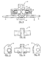
- FIG. 2 illustrates one attachment mechanism 20 for attaching a respective end of the first cable 26 to the floor 18.
- a lug fitting 30 may be mounted to the floor and the attachment mechanism 20 may include a clevis fitting 32 that is rotatably attached to the lug fitting, such as with a pin 34.
- the attachment of the end of the first cable 26 to the floor 18 may also include a turnbuckle 36 and a hexagonal fitting 38 for providing adjustability in tensioning of the first cable.
- the attachment mechanism 20 may also include a swage link 40 that is mechanically connected to the first cable 26.
- the attachment mechanism 20 may also include a tensioner compression spring 42 disposed within a cavity defined by the swage link 40.
- the tensioner compression spring 42 is configured to allow a limited degree of lengthening of the first cable 26, such as 0.3 inches in one embodiment, so as to accommodate thermal expansion and pressurization variations.
- a similar attachment mechanism 20 may also affix the other end of the first cable 26 to the floor 18, such as on the opposite side of the aircraft, in order to provide additional lengthening of the first cable, such as 0.6 inches in one embodiment.
- the first cable 26 may be attached to the side walls at a plurality of discrete locations designated as 22 as will be described below. Between the discrete locations at which the first cable 26 is attached to the side walls 14, the first cable may be spaced apart from the side wall by a distance.
- the barrier curtain 12 may be attached to the side walls 14 in those regions in which the first cable 26 is spaced from the side wall.
- FIG. 3 illustrates a cross-sectional view taken along line 3-3 of FIG. 1 of one technique for attaching the barrier curtain to a side wall.
- the first cable 26 may extend through a ring 50.
- the barrier curtain 12 is attached to a second cable 52 that also extends through the same ring 50.
- FIG. 1 illustrates the first and second cables 26, 52 as well as the rings 50 through which the cables extend with the rings depicted as hash marks extending across each of the first and second cables.
- the barrier curtain 12 may be attached to the second cable 52 in various manners, but, in one embodiment, the barrier curtain includes a plurality of reinforced eyelets through which the rings 50 extend with the barrier curtain then being wrapped about the second cable with the overlapping portions of the barrier curtain being stitched together as shown at 54 of FIG. 3 .
- the first and second cables 26, 52 may, in one embodiment, be the same type of cable, such as a nylon coated, stainless steel cable.
- the barrier curtain 12 may extend beyond the second cable 52 and may be attached to a side wall 14 or ceiling panel 16.
- the edge of the barrier curtain 12 may be attached to a side wall 14 or ceiling panel 16 in various manners including, in one embodiment as shown in FIG. 3 and, in more detail, in FIG. 4 , with a seal.
- the seal may include a channel 60, such as a fiberglass channel, that is attached to the side wall 14 or ceiling panel 16 with, for example, double-back foam tape 61.
- the seal may also include foam portions 62 to which the edge of the barrier curtain 12 is stitched as shown at 64.
- the foam portions 62 may, in turn, be secured within the channel 60 by a fastener, such as a lift-the-dot fastener.
- a fastener such as a lift-the-dot fastener.
- the lift-the-dot fastener may include a lift-the-dot stud 66 that is attached to the side wall 14 or ceiling panel 16 with a screw 68 and washer 70 and that engages a lift-the-dot grommet 72 having a dot 74 disposed within the channel 60 and secured to the foam portions 62.
- the edge of the barrier curtain 12 may be attached to the foam portions 62, such as by stitching 64, with the foam portions, in turn, secured to the lift-the-dot grommet 72 with the resulting assembly then being snapped into engagement with the lift-the-dot stud 66 so as to secure the edge of the barrier curtain to a side wall or a ceiling panel in order to provide for the environmental isolation.
- a reinforcement material 76 such as Kevlar material, may be attached to the barrier curtain 12 so as to avoid abrasion or puncturing of the barrier curtain by the lift-to-dot fastener.
- the portion of the barrier curtain 12 between the second cable 52 and the seal may include a slack region 56 to accommodate some flexure of the barrier curtain and the first and second cables without disturbing the seal between the edge of the barrier curtain and the side wall 14 or ceiling panel 16.
- the apparatus of one embodiment may include a plurality of seals positioned along the side walls 14 and/or ceiling panels 14 in those regions in which the first cable 26 is spaced from the side wall or ceiling panel.
- the first cable 26 is attached to the side wall 14 and/or ceiling panels 16 at a number of different positions.
- the first cable 26 may be attached to the side walls 14 and/or ceiling panels 16 in various manners, one mechanism for attaching the first cable to a side wall or ceiling panel is shown, for example, in FIGs. 5 and 6 .
- a hook 80 may be attached to the side wall 14 or ceiling panel 16 and the first cable 26 may be engaged by the hook so as to be held proximate the side wall or ceiling panel.
- the hook 80 may include or otherwise be carried by a support bracket 82 that extends lengthwise so as to attached to the frame. As shown in FIG.
- first and second cables 26, 52 may both extend through a plurality of rings 50 and the edge of barrier curtain 12 may be attached to the side wall 14 and/or ceiling panels 16 in the manner described above in conjunction with FIGs. 3 and 4 so as to provide for the environmental isolation.
- FIGs 5 and 6 Although one mechanism for attaching the first cable 26 to a side wall 14 or ceiling panel 16 is shown in FIGs 5 and 6 and described above, other mechanisms may be employed including mechanisms that employ claims or other fasteners instead of hooks 80.
- the barrier curtain 12 provides for environmental isolation between the adjacent volumes, such as between a passenger compartment and a cargo compartment, thereby reducing or preventing smoke and flame dispersion between the adjacent compartments.
- the barrier curtain 12 is able to accommodate the pressure differential that is anticipated to exist from time to time between the passenger compartment and the cargo compartment during normal operating conditions.
- the apparatus is configured to release the barrier curtain 12 such that the barrier curtain no longer separates the adjacent volume and, in one embodiment, may drop to the floor so as to permit the volumes to be equally pressurized.
- the first cable 26 may be attached to a side wall 14 or a ceiling panel 16 by a cable release mechanism 24 that secures the first cable to the side wall or the ceiling panel, but that provides for separation of the first cable from the side wall or ceiling panel in an instance in which the load applied to the release mechanism, such as due to differential pressure on the barrier curtain, exceeds a predetermined amount.
- the cable release mechanism 24 may be positioned in various locations along the side walls 14 and the ceiling panels 16
- the cable release mechanism of one embodiment is positioned proximate a medial portion of the first cable 26, such as about halfway between the opposed ends of the first cable.
- the cable release mechanism 24 of the illustrated embodiment is attached to a ceiling panel 16.
- the cable release mechanism 24 may be constructed in various manners so as to secure the first cable 26 to a side wall 14 or ceiling panel 16 during normal operating conditions, but to release the first cable in an instance in which the release mechanism is subjected to a load that exceeds the predetermined amount.
- a cable release mechanism is shown in FIG. 7 and includes a clevis fitting 90 that may be attached via attachment flanges 92 to a lug which, in turn, is attached to the ceiling panel 16. Further details regarding the clevis fitting 90 are shown in Figures 10-13 . The clevis fitting 90 of this embodiment is also attached to the first cable 26.
- the cable release mechanism 24 also includes a hook 94 attached to the clevis fitting 90 for engaging the first cable 26. Further details regarding the hook 94 are shown in Figures 14-16 .
- the first cable may be separated and, as such, may include first and second portions that are each engaged by the hook 94 of the cable release mechanism.
- a first portion of the first cable 26 may extend from the floor 18 on one side of the aircraft to the cable release mechanism 24, while the second portion of the first cable may extend from the floor on the other side of the aircraft to the cable release mechanism.
- the ends of the cable portions that are engaged by the hook 94 of the cable release mechanism 24 may each include a cable end fitting 96 that may define a profile that is securely engaged by the hook of the cable release mechanism as shown in FIG. 9 .
- the hook 94 may be attached to the clevis fitting 90 in various manners, but, in one embodiment, is attached to the clevis fitting by a ball detent mechanism comprising a pair of set screws 98, Bellville washers 100 and ball bearings 102 as also shown in FIG. 9 .
- the ball detent mechanism is configured to secure the hook 94 to the clevis fitting 90 until a separation force that equals or exceeds a predetermined threshold is applied to the hook.
- the first cable 26 may be secured within the hook 94 by a clip 104 that is attached to the clevis fitting, 90 such as with one or more screws 106.
- a clip 104 may include a portion having a profile, such as a tapered profile, configured to engage the first cable 26, such as the cable end fittings 96 of the first and second portions of the first cable and to secure the first cable within the hook 94. See, for example, Figures 17 and 18 which show additional details of the clip 104.
- the ball detent mechanism may release the hook 94 from the clevis fitting 90 such that the first and second portions of the first cable are, in turn, released, detached or the like. Without the support by the first cable 26, the attachment of the edge of the barrier curtain 12 to the side walls 14 and the ceiling panels 16 by the plurality of seals is overcome such that the barrier curtain pulls away from the side walls and the ceiling panels. The first and second portions of the first cable 26 may then pull through the plurality of rings 50 so as to release the barrier curtain 12 which then drops to the floor 18 so as to permit the equalization of pressure between the adjacent volumes, such as between the passenger compartment and the cargo compartment.
- the cable release mechanism 24 may be configured to release the first cable 26 in response to a load that exceeds a predetermined amount.
- the cable release mechanism 24 secures the first cable while the barrier curtain is subjected to loads that do not exceed the predetermined amount.
- the barrier curtain 12 is subjected to a load that exceeds the predetermined amount, such as in response to an explosive decompression, the first cable 26 is released and the barrier curtain drops to the floor 18.
- the cable release mechanism 24 may be constructed in other fashions.
- Figures 19 and 20 illustrate a cable release mechanism 24 that is configured to engage the cable end fittings 96 mounted upon the ends of first and second portions of the first cable 26.
- Each of the cable end fittings 96 of this embodiment include a dimple or other recessed portion that is engaged by the ball bearing 102 of a ball detent mechanism.
- the ball detent mechanism and, in turn, the cable release mechanism 24 releases the cable end fittings 96 to permit the barrier curtain 12 to be released.
- the cable release mechanism 24 may include a shear pin 110 carried by the cable end fitting 96 of one portion of the first cable 26 and a slip fitting 112 carried by the cable end fitting of the other portion of the first cable.
- the shear pin 110 is disposed within a slot defined by the slip fitting 112 in instances in which the load carried by the first cable 26 is no more than a predetermined amount. However, in instances in which the load carried by the first cable 26 exceeds the predetermined amount, the shear pin 110 may be sheared off, thereby allowing the portions of the first cable to separate and, in turn, permitting the barrier curtain 12 to be released.
Applications Claiming Priority (2)
| Application Number | Priority Date | Filing Date | Title |
|---|---|---|---|
| US201261641102P | 2012-05-01 | 2012-05-01 | |
| US13/773,049 US9556667B2 (en) | 2012-05-01 | 2013-02-21 | Method and apparatus for establishing an environmentally isolated volume |
Publications (3)
| Publication Number | Publication Date |
|---|---|
| EP2660142A2 true EP2660142A2 (de) | 2013-11-06 |
| EP2660142A3 EP2660142A3 (de) | 2018-03-07 |
| EP2660142B1 EP2660142B1 (de) | 2022-12-07 |
Family
ID=48325416
Family Applications (1)
| Application Number | Title | Priority Date | Filing Date |
|---|---|---|---|
| EP13166144.9A Active EP2660142B1 (de) | 2012-05-01 | 2013-05-01 | Verfahren und Vorrichtung zur Herstellung eines umgebungsisolierten Volumens |
Country Status (2)
| Country | Link |
|---|---|
| US (2) | US9556667B2 (de) |
| EP (1) | EP2660142B1 (de) |
Cited By (3)
| Publication number | Priority date | Publication date | Assignee | Title |
|---|---|---|---|---|
| DE102018110379A1 (de) * | 2018-04-30 | 2019-10-31 | Airbus Operations Gmbh | System zum Verspannen eines Zugelements in einem Fahrzeug |
| CN111186586A (zh) * | 2019-12-11 | 2020-05-22 | 贵州电网有限责任公司 | 一种适用于无人机的烟雾发射装置 |
| CN117655961A (zh) * | 2024-01-31 | 2024-03-08 | 无锡阳光精机股份有限公司 | 一种用于电主轴喷淋测试的工件夹持装置 |
Families Citing this family (4)
| Publication number | Priority date | Publication date | Assignee | Title |
|---|---|---|---|---|
| US9556667B2 (en) * | 2012-05-01 | 2017-01-31 | The Boeing Company | Method and apparatus for establishing an environmentally isolated volume |
| US20180016093A1 (en) * | 2015-02-13 | 2018-01-18 | Driessen Aerospace Group N.V. | Cargo container closure systems |
| EP3998190A1 (de) * | 2021-02-19 | 2022-05-18 | Lilium eAircraft GmbH | Auskleidung für einen fracht- und / oder zubehörraum eines flugzeugs, flugzeug mit einer solchen auskleidung und verfahren zum auskleiden eines fracht- oder zubehörraums eines flugzeugs |
| US20230415899A1 (en) * | 2022-06-23 | 2023-12-28 | The Boeing Company | Aircraft Ceiling Resettable Decompression Roller Assembly |
Citations (1)
| Publication number | Priority date | Publication date | Assignee | Title |
|---|---|---|---|---|
| US20030192989A1 (en) * | 2002-04-10 | 2003-10-16 | Frank Owen | Security bulkhead and door construction |
Family Cites Families (33)
| Publication number | Priority date | Publication date | Assignee | Title |
|---|---|---|---|---|
| US898788A (en) * | 1907-09-11 | 1908-09-15 | Charles A Scheif | Curtain-fixture. |
| US2605064A (en) | 1947-07-10 | 1952-07-29 | Frank L Davis | Cargo securing system |
| US3169781A (en) * | 1963-01-08 | 1965-02-16 | Samuel A Abruzzino | Safety net for vehicle occupants |
| US3294034A (en) * | 1964-06-18 | 1966-12-27 | American Mach & Foundry | Cargo container for airplanes |
| US3486423A (en) * | 1966-06-03 | 1969-12-30 | Illinois Creamery Supply Co | Machine for automatically forming,filling,closing and sealing plastic coated gable top cartons of paperboard or the like |
| US3872634A (en) | 1972-07-31 | 1975-03-25 | Seaman Corp | Rigid frame, tensioned fabric structure |
| US4046186A (en) * | 1976-02-12 | 1977-09-06 | Transequip Inc. | Cargo container opening cover |
| US4091857A (en) * | 1977-07-05 | 1978-05-30 | Plastic Products, Inc. | Cable-suspended draw-curtain system |
| US4290243A (en) | 1980-03-27 | 1981-09-22 | Seaman Corporation | Building membrane hold-down system |
| US4429730A (en) * | 1981-01-28 | 1984-02-07 | Transequip Limited | Cargo container cover |
| US4538663A (en) * | 1983-04-21 | 1985-09-03 | Robert Looker | Cargo container |
| US4601405A (en) * | 1985-09-26 | 1986-07-22 | The Boeing Company | Closure system for a containerized cargo handling sleeve |
| US5069401A (en) * | 1989-11-15 | 1991-12-03 | The Boeing Company | Compartment partition and pressure relief door therefor |
| US5217132A (en) * | 1991-07-29 | 1993-06-08 | Robert Looker | Convertible air cargo container |
| US5407162A (en) * | 1993-08-30 | 1995-04-18 | Manger; Gerald H. | Arched window or arched door drapery-mounting kit |
| US5765883A (en) * | 1995-07-14 | 1998-06-16 | Hartwell Corporation | Adjustable pressure relief latch |
| US6817644B2 (en) * | 1995-11-22 | 2004-11-16 | Exco Automotive Solutions, L.P. | Load retaining barrier net for motor vehicle |
| US5875698A (en) * | 1996-06-17 | 1999-03-02 | Black & Decker Inc. | Blade and motor carrier with height/angle adjustment mechanism |
| US5667002A (en) * | 1996-10-17 | 1997-09-16 | Air Cargo Equipment Corporation | Single-point tensioning door system for containers |
| US6435455B1 (en) * | 1997-08-01 | 2002-08-20 | The Boeing Company | Flow-efficient, static pressure-shielding, fire-resistant decompression panel assembly |
| US6119760A (en) * | 1999-10-06 | 2000-09-19 | Poole; David | Adjustable drape for passenger vehicle |
| GB0122815D0 (en) * | 2001-09-21 | 2001-11-14 | Bridport Aviat Products Ltd | A cargo barrier |
| US6866226B2 (en) * | 2001-10-04 | 2005-03-15 | Hartwell Corporation | Pressure responsive blowout latch |
| US6863980B2 (en) | 2002-10-08 | 2005-03-08 | The Boeing Company | Monolithic composite firewall |
| US6766849B1 (en) * | 2003-09-10 | 2004-07-27 | Lian Fa Enterprise Co., Ltd. | Curtain track adjustment assembly |
| US7530529B2 (en) * | 2005-07-12 | 2009-05-12 | Airbus | Separation wall in an aircraft cabin |
| US7264284B2 (en) * | 2005-09-29 | 2007-09-04 | Ming-Piao Hsu | Door catch |
| US20080202711A1 (en) * | 2007-02-26 | 2008-08-28 | Source Global Enterprises, Inc. | Apparatus for Hanging Curtains |
| DE102008025390A1 (de) * | 2008-05-28 | 2010-01-28 | Airbus Deutschland Gmbh | Anordnung zum Unterteilen eines Raums in mehrere Bereiche |
| US20110101187A1 (en) * | 2009-10-29 | 2011-05-05 | Kevin Shaha | Artwork holder with multiple mountings |
| US8479801B2 (en) * | 2010-11-16 | 2013-07-09 | Advanced Composite Structures, Llc | Fabric closure with an access opening for cargo containers |
| US9556667B2 (en) * | 2012-05-01 | 2017-01-31 | The Boeing Company | Method and apparatus for establishing an environmentally isolated volume |
| US8857762B2 (en) * | 2012-06-25 | 2014-10-14 | The Boeing Company | Method and apparatus for establishing an environmentally isolated volume |
-
2013
- 2013-02-21 US US13/773,049 patent/US9556667B2/en active Active
- 2013-05-01 EP EP13166144.9A patent/EP2660142B1/de active Active
-
2017
- 2017-01-20 US US15/411,352 patent/US10220947B2/en active Active
Patent Citations (1)
| Publication number | Priority date | Publication date | Assignee | Title |
|---|---|---|---|---|
| US20030192989A1 (en) * | 2002-04-10 | 2003-10-16 | Frank Owen | Security bulkhead and door construction |
Cited By (5)
| Publication number | Priority date | Publication date | Assignee | Title |
|---|---|---|---|---|
| DE102018110379A1 (de) * | 2018-04-30 | 2019-10-31 | Airbus Operations Gmbh | System zum Verspannen eines Zugelements in einem Fahrzeug |
| US11161612B2 (en) | 2018-04-30 | 2021-11-02 | Airbus Operations Gmbh | System for bracing a tensile element in a vehicle |
| CN111186586A (zh) * | 2019-12-11 | 2020-05-22 | 贵州电网有限责任公司 | 一种适用于无人机的烟雾发射装置 |
| CN117655961A (zh) * | 2024-01-31 | 2024-03-08 | 无锡阳光精机股份有限公司 | 一种用于电主轴喷淋测试的工件夹持装置 |
| CN117655961B (zh) * | 2024-01-31 | 2024-04-05 | 无锡阳光精机股份有限公司 | 一种用于电主轴喷淋测试的工件夹持装置 |
Also Published As
| Publication number | Publication date |
|---|---|
| US9556667B2 (en) | 2017-01-31 |
| US10220947B2 (en) | 2019-03-05 |
| US20170129609A1 (en) | 2017-05-11 |
| EP2660142B1 (de) | 2022-12-07 |
| EP2660142A3 (de) | 2018-03-07 |
| US20130292069A1 (en) | 2013-11-07 |
Similar Documents
| Publication | Publication Date | Title |
|---|---|---|
| US10220947B2 (en) | Method and apparatus for establishing an environmentally isolated volume | |
| US8857762B2 (en) | Method and apparatus for establishing an environmentally isolated volume | |
| EP2277773B1 (de) | Flugzeug mit einem selbsttragenden Kabinenstrukturbauteil und Verfahren zur Montage eines Kabinenstrukturbauteils in einem Flugzeug | |
| CA2784011C (en) | Fireproof bidirectional decompression panel | |
| US10472067B2 (en) | Separating device for separating two zones of a passenger cabin equipped with overhead luggage bins comprising a movable shell | |
| CN101506036B (zh) | 框架元件、飞行器部件组装系统以及在飞行器中安装部件的方法 | |
| EP3010805B1 (de) | Selbstspannender gurt | |
| CN102239086A (zh) | 贴在机身的侧向延伸部上以将其固定的飞行器吊架刚性结构 | |
| CN103582595A (zh) | 用于隔离框架部件的系统和方法 | |
| EP3024729B1 (de) | Triebwerkspylon für luftfahrzeug | |
| US20200317322A1 (en) | Emergency exit assembly for an aircraft | |
| US6010286A (en) | Apparatus for rigidly retaining cargo | |
| US10793276B2 (en) | Class divider for an aircraft passenger cabin | |
| US10220227B2 (en) | Fire extinguishing system of aircraft, and aircraft | |
| SE514855C2 (sv) | Skyddsanordning för fordon | |
| US20220387827A1 (en) | Arrangement provided with an emergency evacuation system | |
| US10377463B2 (en) | Aircraft comprising a hatch and a fall-protection device | |
| EP3403921A1 (de) | Abgeteilte barriere mit dekompressionsplatten | |
| US10899425B2 (en) | Door frame stabilization | |
| CN111623028A (zh) | 一种连接装置 | |
| CN102026685B (zh) | 用于建筑物疏散线路的锚 | |
| CN109573794A (zh) | 一种带限制功能的同步带电梯门刀组件 |
Legal Events
| Date | Code | Title | Description |
|---|---|---|---|
| PUAI | Public reference made under article 153(3) epc to a published international application that has entered the european phase |
Free format text: ORIGINAL CODE: 0009012 |
|
| 17P | Request for examination filed |
Effective date: 20130501 |
|
| AK | Designated contracting states |
Kind code of ref document: A2 Designated state(s): AL AT BE BG CH CY CZ DE DK EE ES FI FR GB GR HR HU IE IS IT LI LT LU LV MC MK MT NL NO PL PT RO RS SE SI SK SM TR |
|
| AX | Request for extension of the european patent |
Extension state: BA ME |
|
| PUAL | Search report despatched |
Free format text: ORIGINAL CODE: 0009013 |
|
| AK | Designated contracting states |
Kind code of ref document: A3 Designated state(s): AL AT BE BG CH CY CZ DE DK EE ES FI FR GB GR HR HU IE IS IT LI LT LU LV MC MK MT NL NO PL PT RO RS SE SI SK SM TR |
|
| AX | Request for extension of the european patent |
Extension state: BA ME |
|
| RIC1 | Information provided on ipc code assigned before grant |
Ipc: B64D 45/00 20060101ALI20180129BHEP Ipc: B64C 1/06 20060101AFI20180129BHEP |
|
| GRAP | Despatch of communication of intention to grant a patent |
Free format text: ORIGINAL CODE: EPIDOSNIGR1 |
|
| STAA | Information on the status of an ep patent application or granted ep patent |
Free format text: STATUS: GRANT OF PATENT IS INTENDED |
|
| INTG | Intention to grant announced |
Effective date: 20200422 |
|
| RIN1 | Information on inventor provided before grant (corrected) |
Inventor name: CLOS, WILLIAM ROBERT |
|
| GRAJ | Information related to disapproval of communication of intention to grant by the applicant or resumption of examination proceedings by the epo deleted |
Free format text: ORIGINAL CODE: EPIDOSDIGR1 |
|
| STAA | Information on the status of an ep patent application or granted ep patent |
Free format text: STATUS: REQUEST FOR EXAMINATION WAS MADE |
|
| INTC | Intention to grant announced (deleted) | ||
| STAA | Information on the status of an ep patent application or granted ep patent |
Free format text: STATUS: EXAMINATION IS IN PROGRESS |
|
| 17Q | First examination report despatched |
Effective date: 20201005 |
|
| STAA | Information on the status of an ep patent application or granted ep patent |
Free format text: STATUS: EXAMINATION IS IN PROGRESS |
|
| GRAP | Despatch of communication of intention to grant a patent |
Free format text: ORIGINAL CODE: EPIDOSNIGR1 |
|
| STAA | Information on the status of an ep patent application or granted ep patent |
Free format text: STATUS: GRANT OF PATENT IS INTENDED |
|
| INTG | Intention to grant announced |
Effective date: 20220217 |
|
| GRAJ | Information related to disapproval of communication of intention to grant by the applicant or resumption of examination proceedings by the epo deleted |
Free format text: ORIGINAL CODE: EPIDOSDIGR1 |
|
| STAA | Information on the status of an ep patent application or granted ep patent |
Free format text: STATUS: EXAMINATION IS IN PROGRESS |
|
| GRAP | Despatch of communication of intention to grant a patent |
Free format text: ORIGINAL CODE: EPIDOSNIGR1 |
|
| STAA | Information on the status of an ep patent application or granted ep patent |
Free format text: STATUS: GRANT OF PATENT IS INTENDED |
|
| INTC | Intention to grant announced (deleted) | ||
| INTG | Intention to grant announced |
Effective date: 20220715 |
|
| GRAS | Grant fee paid |
Free format text: ORIGINAL CODE: EPIDOSNIGR3 |
|
| GRAA | (expected) grant |
Free format text: ORIGINAL CODE: 0009210 |
|
| STAA | Information on the status of an ep patent application or granted ep patent |
Free format text: STATUS: THE PATENT HAS BEEN GRANTED |
|
| AK | Designated contracting states |
Kind code of ref document: B1 Designated state(s): AL AT BE BG CH CY CZ DE DK EE ES FI FR GB GR HR HU IE IS IT LI LT LU LV MC MK MT NL NO PL PT RO RS SE SI SK SM TR |
|
| REG | Reference to a national code |
Ref country code: GB Ref legal event code: FG4D |
|
| REG | Reference to a national code |
Ref country code: CH Ref legal event code: EP Ref country code: AT Ref legal event code: REF Ref document number: 1536166 Country of ref document: AT Kind code of ref document: T Effective date: 20221215 |
|
| REG | Reference to a national code |
Ref country code: DE Ref legal event code: R096 Ref document number: 602013082998 Country of ref document: DE |
|
| REG | Reference to a national code |
Ref country code: IE Ref legal event code: FG4D |
|
| RAP4 | Party data changed (patent owner data changed or rights of a patent transferred) |
Owner name: THE BOEING COMPANY |
|
| REG | Reference to a national code |
Ref country code: LT Ref legal event code: MG9D |
|
| REG | Reference to a national code |
Ref country code: NL Ref legal event code: MP Effective date: 20221207 |
|
| PG25 | Lapsed in a contracting state [announced via postgrant information from national office to epo] |
Ref country code: SE Free format text: LAPSE BECAUSE OF FAILURE TO SUBMIT A TRANSLATION OF THE DESCRIPTION OR TO PAY THE FEE WITHIN THE PRESCRIBED TIME-LIMIT Effective date: 20221207 Ref country code: NO Free format text: LAPSE BECAUSE OF FAILURE TO SUBMIT A TRANSLATION OF THE DESCRIPTION OR TO PAY THE FEE WITHIN THE PRESCRIBED TIME-LIMIT Effective date: 20230307 Ref country code: LT Free format text: LAPSE BECAUSE OF FAILURE TO SUBMIT A TRANSLATION OF THE DESCRIPTION OR TO PAY THE FEE WITHIN THE PRESCRIBED TIME-LIMIT Effective date: 20221207 Ref country code: FI Free format text: LAPSE BECAUSE OF FAILURE TO SUBMIT A TRANSLATION OF THE DESCRIPTION OR TO PAY THE FEE WITHIN THE PRESCRIBED TIME-LIMIT Effective date: 20221207 Ref country code: ES Free format text: LAPSE BECAUSE OF FAILURE TO SUBMIT A TRANSLATION OF THE DESCRIPTION OR TO PAY THE FEE WITHIN THE PRESCRIBED TIME-LIMIT Effective date: 20221207 |
|
| REG | Reference to a national code |
Ref country code: AT Ref legal event code: MK05 Ref document number: 1536166 Country of ref document: AT Kind code of ref document: T Effective date: 20221207 |
|
| PG25 | Lapsed in a contracting state [announced via postgrant information from national office to epo] |
Ref country code: RS Free format text: LAPSE BECAUSE OF FAILURE TO SUBMIT A TRANSLATION OF THE DESCRIPTION OR TO PAY THE FEE WITHIN THE PRESCRIBED TIME-LIMIT Effective date: 20221207 Ref country code: PL Free format text: LAPSE BECAUSE OF FAILURE TO SUBMIT A TRANSLATION OF THE DESCRIPTION OR TO PAY THE FEE WITHIN THE PRESCRIBED TIME-LIMIT Effective date: 20221207 Ref country code: LV Free format text: LAPSE BECAUSE OF FAILURE TO SUBMIT A TRANSLATION OF THE DESCRIPTION OR TO PAY THE FEE WITHIN THE PRESCRIBED TIME-LIMIT Effective date: 20221207 Ref country code: HR Free format text: LAPSE BECAUSE OF FAILURE TO SUBMIT A TRANSLATION OF THE DESCRIPTION OR TO PAY THE FEE WITHIN THE PRESCRIBED TIME-LIMIT Effective date: 20221207 Ref country code: GR Free format text: LAPSE BECAUSE OF FAILURE TO SUBMIT A TRANSLATION OF THE DESCRIPTION OR TO PAY THE FEE WITHIN THE PRESCRIBED TIME-LIMIT Effective date: 20230308 |
|
| PG25 | Lapsed in a contracting state [announced via postgrant information from national office to epo] |
Ref country code: NL Free format text: LAPSE BECAUSE OF FAILURE TO SUBMIT A TRANSLATION OF THE DESCRIPTION OR TO PAY THE FEE WITHIN THE PRESCRIBED TIME-LIMIT Effective date: 20221207 |
|
| PG25 | Lapsed in a contracting state [announced via postgrant information from national office to epo] |
Ref country code: SM Free format text: LAPSE BECAUSE OF FAILURE TO SUBMIT A TRANSLATION OF THE DESCRIPTION OR TO PAY THE FEE WITHIN THE PRESCRIBED TIME-LIMIT Effective date: 20221207 Ref country code: RO Free format text: LAPSE BECAUSE OF FAILURE TO SUBMIT A TRANSLATION OF THE DESCRIPTION OR TO PAY THE FEE WITHIN THE PRESCRIBED TIME-LIMIT Effective date: 20221207 Ref country code: PT Free format text: LAPSE BECAUSE OF FAILURE TO SUBMIT A TRANSLATION OF THE DESCRIPTION OR TO PAY THE FEE WITHIN THE PRESCRIBED TIME-LIMIT Effective date: 20230410 Ref country code: EE Free format text: LAPSE BECAUSE OF FAILURE TO SUBMIT A TRANSLATION OF THE DESCRIPTION OR TO PAY THE FEE WITHIN THE PRESCRIBED TIME-LIMIT Effective date: 20221207 Ref country code: CZ Free format text: LAPSE BECAUSE OF FAILURE TO SUBMIT A TRANSLATION OF THE DESCRIPTION OR TO PAY THE FEE WITHIN THE PRESCRIBED TIME-LIMIT Effective date: 20221207 Ref country code: AT Free format text: LAPSE BECAUSE OF FAILURE TO SUBMIT A TRANSLATION OF THE DESCRIPTION OR TO PAY THE FEE WITHIN THE PRESCRIBED TIME-LIMIT Effective date: 20221207 |
|
| PGFP | Annual fee paid to national office [announced via postgrant information from national office to epo] |
Ref country code: FR Payment date: 20230526 Year of fee payment: 11 Ref country code: DE Payment date: 20230530 Year of fee payment: 11 |
|
| PG25 | Lapsed in a contracting state [announced via postgrant information from national office to epo] |
Ref country code: SK Free format text: LAPSE BECAUSE OF FAILURE TO SUBMIT A TRANSLATION OF THE DESCRIPTION OR TO PAY THE FEE WITHIN THE PRESCRIBED TIME-LIMIT Effective date: 20221207 Ref country code: IS Free format text: LAPSE BECAUSE OF FAILURE TO SUBMIT A TRANSLATION OF THE DESCRIPTION OR TO PAY THE FEE WITHIN THE PRESCRIBED TIME-LIMIT Effective date: 20230407 Ref country code: AL Free format text: LAPSE BECAUSE OF FAILURE TO SUBMIT A TRANSLATION OF THE DESCRIPTION OR TO PAY THE FEE WITHIN THE PRESCRIBED TIME-LIMIT Effective date: 20221207 |
|
| REG | Reference to a national code |
Ref country code: DE Ref legal event code: R097 Ref document number: 602013082998 Country of ref document: DE |
|
| PLBE | No opposition filed within time limit |
Free format text: ORIGINAL CODE: 0009261 |
|
| STAA | Information on the status of an ep patent application or granted ep patent |
Free format text: STATUS: NO OPPOSITION FILED WITHIN TIME LIMIT |
|
| PG25 | Lapsed in a contracting state [announced via postgrant information from national office to epo] |
Ref country code: DK Free format text: LAPSE BECAUSE OF FAILURE TO SUBMIT A TRANSLATION OF THE DESCRIPTION OR TO PAY THE FEE WITHIN THE PRESCRIBED TIME-LIMIT Effective date: 20221207 |
|
| PGFP | Annual fee paid to national office [announced via postgrant information from national office to epo] |
Ref country code: GB Payment date: 20230529 Year of fee payment: 11 |
|
| 26N | No opposition filed |
Effective date: 20230908 |
|
| PG25 | Lapsed in a contracting state [announced via postgrant information from national office to epo] |
Ref country code: SI Free format text: LAPSE BECAUSE OF FAILURE TO SUBMIT A TRANSLATION OF THE DESCRIPTION OR TO PAY THE FEE WITHIN THE PRESCRIBED TIME-LIMIT Effective date: 20221207 |
|
| REG | Reference to a national code |
Ref country code: CH Ref legal event code: PL |
|
| PG25 | Lapsed in a contracting state [announced via postgrant information from national office to epo] |
Ref country code: MC Free format text: LAPSE BECAUSE OF FAILURE TO SUBMIT A TRANSLATION OF THE DESCRIPTION OR TO PAY THE FEE WITHIN THE PRESCRIBED TIME-LIMIT Effective date: 20221207 |
|
| REG | Reference to a national code |
Ref country code: BE Ref legal event code: MM Effective date: 20230531 |
|
| PG25 | Lapsed in a contracting state [announced via postgrant information from national office to epo] |
Ref country code: MC Free format text: LAPSE BECAUSE OF FAILURE TO SUBMIT A TRANSLATION OF THE DESCRIPTION OR TO PAY THE FEE WITHIN THE PRESCRIBED TIME-LIMIT Effective date: 20221207 Ref country code: LU Free format text: LAPSE BECAUSE OF NON-PAYMENT OF DUE FEES Effective date: 20230501 Ref country code: LI Free format text: LAPSE BECAUSE OF NON-PAYMENT OF DUE FEES Effective date: 20230531 Ref country code: CH Free format text: LAPSE BECAUSE OF NON-PAYMENT OF DUE FEES Effective date: 20230531 |
|
| REG | Reference to a national code |
Ref country code: IE Ref legal event code: MM4A |
|
| PG25 | Lapsed in a contracting state [announced via postgrant information from national office to epo] |
Ref country code: IE Free format text: LAPSE BECAUSE OF NON-PAYMENT OF DUE FEES Effective date: 20230501 |