EP2659211B1 - Method for producing a methane-rich stream and a c2+ hydrocarbon-rich stream, and associated equipment - Google Patents
Method for producing a methane-rich stream and a c2+ hydrocarbon-rich stream, and associated equipment Download PDFInfo
- Publication number
- EP2659211B1 EP2659211B1 EP11802438.9A EP11802438A EP2659211B1 EP 2659211 B1 EP2659211 B1 EP 2659211B1 EP 11802438 A EP11802438 A EP 11802438A EP 2659211 B1 EP2659211 B1 EP 2659211B1
- Authority
- EP
- European Patent Office
- Prior art keywords
- stream
- fraction
- dynamic expansion
- feed
- expansion turbine
- Prior art date
- Legal status (The legal status is an assumption and is not a legal conclusion. Google has not performed a legal analysis and makes no representation as to the accuracy of the status listed.)
- Active
Links
- VNWKTOKETHGBQD-UHFFFAOYSA-N methane Chemical compound C VNWKTOKETHGBQD-UHFFFAOYSA-N 0.000 title claims description 90
- 229930195733 hydrocarbon Natural products 0.000 title claims description 29
- 150000002430 hydrocarbons Chemical class 0.000 title claims description 29
- 238000004519 manufacturing process Methods 0.000 title claims description 16
- 239000004215 Carbon black (E152) Substances 0.000 title claims description 12
- 238000000034 method Methods 0.000 claims description 69
- 238000009434 installation Methods 0.000 claims description 35
- 238000004821 distillation Methods 0.000 claims description 25
- 238000010992 reflux Methods 0.000 claims description 19
- 239000007788 liquid Substances 0.000 claims description 18
- 238000011144 upstream manufacturing Methods 0.000 claims description 15
- 238000001816 cooling Methods 0.000 claims description 13
- 239000003507 refrigerant Substances 0.000 claims description 11
- 230000006835 compression Effects 0.000 claims description 9
- 238000007906 compression Methods 0.000 claims description 9
- 238000010438 heat treatment Methods 0.000 claims 2
- 238000002347 injection Methods 0.000 claims 2
- 239000007924 injection Substances 0.000 claims 2
- OTMSDBZUPAUEDD-UHFFFAOYSA-N Ethane Chemical compound CC OTMSDBZUPAUEDD-UHFFFAOYSA-N 0.000 description 17
- ATUOYWHBWRKTHZ-UHFFFAOYSA-N Propane Chemical compound CCC ATUOYWHBWRKTHZ-UHFFFAOYSA-N 0.000 description 14
- 238000011084 recovery Methods 0.000 description 13
- 239000007789 gas Substances 0.000 description 11
- 229910052799 carbon Inorganic materials 0.000 description 10
- OFBQJSOFQDEBGM-UHFFFAOYSA-N n-pentane Natural products CCCCC OFBQJSOFQDEBGM-UHFFFAOYSA-N 0.000 description 8
- IJGRMHOSHXDMSA-UHFFFAOYSA-N Atomic nitrogen Chemical compound N#N IJGRMHOSHXDMSA-UHFFFAOYSA-N 0.000 description 7
- 239000001294 propane Substances 0.000 description 7
- CURLTUGMZLYLDI-UHFFFAOYSA-N Carbon dioxide Chemical compound O=C=O CURLTUGMZLYLDI-UHFFFAOYSA-N 0.000 description 6
- 238000010586 diagram Methods 0.000 description 6
- 239000003345 natural gas Substances 0.000 description 6
- 230000003068 static effect Effects 0.000 description 5
- NNPPMTNAJDCUHE-UHFFFAOYSA-N isobutane Chemical compound CC(C)C NNPPMTNAJDCUHE-UHFFFAOYSA-N 0.000 description 4
- IJDNQMDRQITEOD-UHFFFAOYSA-N n-butane Chemical compound CCCC IJDNQMDRQITEOD-UHFFFAOYSA-N 0.000 description 4
- 238000000926 separation method Methods 0.000 description 4
- 239000001569 carbon dioxide Substances 0.000 description 3
- 229910002092 carbon dioxide Inorganic materials 0.000 description 3
- QWTDNUCVQCZILF-UHFFFAOYSA-N isopentane Chemical compound CCC(C)C QWTDNUCVQCZILF-UHFFFAOYSA-N 0.000 description 3
- 229910052757 nitrogen Inorganic materials 0.000 description 3
- 239000001273 butane Substances 0.000 description 2
- 239000003245 coal Substances 0.000 description 2
- 239000010779 crude oil Substances 0.000 description 2
- 230000003247 decreasing effect Effects 0.000 description 2
- 238000000605 extraction Methods 0.000 description 2
- 238000002156 mixing Methods 0.000 description 2
- 239000000203 mixture Substances 0.000 description 2
- 238000012856 packing Methods 0.000 description 2
- 238000005070 sampling Methods 0.000 description 2
- XLYOFNOQVPJJNP-UHFFFAOYSA-N water Substances O XLYOFNOQVPJJNP-UHFFFAOYSA-N 0.000 description 2
- VGGSQFUCUMXWEO-UHFFFAOYSA-N Ethene Chemical compound C=C VGGSQFUCUMXWEO-UHFFFAOYSA-N 0.000 description 1
- 239000005977 Ethylene Substances 0.000 description 1
- UFHFLCQGNIYNRP-UHFFFAOYSA-N Hydrogen Chemical compound [H][H] UFHFLCQGNIYNRP-UHFFFAOYSA-N 0.000 description 1
- 238000010521 absorption reaction Methods 0.000 description 1
- 238000009833 condensation Methods 0.000 description 1
- 230000005494 condensation Effects 0.000 description 1
- 238000010276 construction Methods 0.000 description 1
- AFABGHUZZDYHJO-UHFFFAOYSA-N dimethyl butane Natural products CCCC(C)C AFABGHUZZDYHJO-UHFFFAOYSA-N 0.000 description 1
- 230000005611 electricity Effects 0.000 description 1
- 238000005265 energy consumption Methods 0.000 description 1
- 238000007667 floating Methods 0.000 description 1
- 239000013505 freshwater Substances 0.000 description 1
- 239000001307 helium Substances 0.000 description 1
- 229910052734 helium Inorganic materials 0.000 description 1
- SWQJXJOGLNCZEY-UHFFFAOYSA-N helium atom Chemical compound [He] SWQJXJOGLNCZEY-UHFFFAOYSA-N 0.000 description 1
- 239000001257 hydrogen Substances 0.000 description 1
- 229910052739 hydrogen Inorganic materials 0.000 description 1
- 239000001282 iso-butane Substances 0.000 description 1
- JCXJVPUVTGWSNB-UHFFFAOYSA-N nitrogen dioxide Inorganic materials O=[N]=O JCXJVPUVTGWSNB-UHFFFAOYSA-N 0.000 description 1
- 239000003921 oil Substances 0.000 description 1
- QQONPFPTGQHPMA-UHFFFAOYSA-N propylene Natural products CC=C QQONPFPTGQHPMA-UHFFFAOYSA-N 0.000 description 1
- 125000004805 propylene group Chemical group [H]C([H])([H])C([H])([*:1])C([H])([H])[*:2] 0.000 description 1
- 239000013535 sea water Substances 0.000 description 1
Images


Classifications
-
- F—MECHANICAL ENGINEERING; LIGHTING; HEATING; WEAPONS; BLASTING
- F25—REFRIGERATION OR COOLING; COMBINED HEATING AND REFRIGERATION SYSTEMS; HEAT PUMP SYSTEMS; MANUFACTURE OR STORAGE OF ICE; LIQUEFACTION SOLIDIFICATION OF GASES
- F25J—LIQUEFACTION, SOLIDIFICATION OR SEPARATION OF GASES OR GASEOUS OR LIQUEFIED GASEOUS MIXTURES BY PRESSURE AND COLD TREATMENT OR BY BRINGING THEM INTO THE SUPERCRITICAL STATE
- F25J3/00—Processes or apparatus for separating the constituents of gaseous or liquefied gaseous mixtures involving the use of liquefaction or solidification
- F25J3/02—Processes or apparatus for separating the constituents of gaseous or liquefied gaseous mixtures involving the use of liquefaction or solidification by rectification, i.e. by continuous interchange of heat and material between a vapour stream and a liquid stream
- F25J3/0204—Processes or apparatus for separating the constituents of gaseous or liquefied gaseous mixtures involving the use of liquefaction or solidification by rectification, i.e. by continuous interchange of heat and material between a vapour stream and a liquid stream characterised by the feed stream
- F25J3/0209—Natural gas or substitute natural gas
-
- F—MECHANICAL ENGINEERING; LIGHTING; HEATING; WEAPONS; BLASTING
- F25—REFRIGERATION OR COOLING; COMBINED HEATING AND REFRIGERATION SYSTEMS; HEAT PUMP SYSTEMS; MANUFACTURE OR STORAGE OF ICE; LIQUEFACTION SOLIDIFICATION OF GASES
- F25J—LIQUEFACTION, SOLIDIFICATION OR SEPARATION OF GASES OR GASEOUS OR LIQUEFIED GASEOUS MIXTURES BY PRESSURE AND COLD TREATMENT OR BY BRINGING THEM INTO THE SUPERCRITICAL STATE
- F25J3/00—Processes or apparatus for separating the constituents of gaseous or liquefied gaseous mixtures involving the use of liquefaction or solidification
- F25J3/02—Processes or apparatus for separating the constituents of gaseous or liquefied gaseous mixtures involving the use of liquefaction or solidification by rectification, i.e. by continuous interchange of heat and material between a vapour stream and a liquid stream
- F25J3/0228—Processes or apparatus for separating the constituents of gaseous or liquefied gaseous mixtures involving the use of liquefaction or solidification by rectification, i.e. by continuous interchange of heat and material between a vapour stream and a liquid stream characterised by the separated product stream
- F25J3/0233—Processes or apparatus for separating the constituents of gaseous or liquefied gaseous mixtures involving the use of liquefaction or solidification by rectification, i.e. by continuous interchange of heat and material between a vapour stream and a liquid stream characterised by the separated product stream separation of CnHm with 1 carbon atom or more
-
- F—MECHANICAL ENGINEERING; LIGHTING; HEATING; WEAPONS; BLASTING
- F25—REFRIGERATION OR COOLING; COMBINED HEATING AND REFRIGERATION SYSTEMS; HEAT PUMP SYSTEMS; MANUFACTURE OR STORAGE OF ICE; LIQUEFACTION SOLIDIFICATION OF GASES
- F25J—LIQUEFACTION, SOLIDIFICATION OR SEPARATION OF GASES OR GASEOUS OR LIQUEFIED GASEOUS MIXTURES BY PRESSURE AND COLD TREATMENT OR BY BRINGING THEM INTO THE SUPERCRITICAL STATE
- F25J3/00—Processes or apparatus for separating the constituents of gaseous or liquefied gaseous mixtures involving the use of liquefaction or solidification
- F25J3/02—Processes or apparatus for separating the constituents of gaseous or liquefied gaseous mixtures involving the use of liquefaction or solidification by rectification, i.e. by continuous interchange of heat and material between a vapour stream and a liquid stream
- F25J3/0228—Processes or apparatus for separating the constituents of gaseous or liquefied gaseous mixtures involving the use of liquefaction or solidification by rectification, i.e. by continuous interchange of heat and material between a vapour stream and a liquid stream characterised by the separated product stream
- F25J3/0238—Processes or apparatus for separating the constituents of gaseous or liquefied gaseous mixtures involving the use of liquefaction or solidification by rectification, i.e. by continuous interchange of heat and material between a vapour stream and a liquid stream characterised by the separated product stream separation of CnHm with 2 carbon atoms or more
-
- F—MECHANICAL ENGINEERING; LIGHTING; HEATING; WEAPONS; BLASTING
- F25—REFRIGERATION OR COOLING; COMBINED HEATING AND REFRIGERATION SYSTEMS; HEAT PUMP SYSTEMS; MANUFACTURE OR STORAGE OF ICE; LIQUEFACTION SOLIDIFICATION OF GASES
- F25J—LIQUEFACTION, SOLIDIFICATION OR SEPARATION OF GASES OR GASEOUS OR LIQUEFIED GASEOUS MIXTURES BY PRESSURE AND COLD TREATMENT OR BY BRINGING THEM INTO THE SUPERCRITICAL STATE
- F25J2200/00—Processes or apparatus using separation by rectification
- F25J2200/02—Processes or apparatus using separation by rectification in a single pressure main column system
-
- F—MECHANICAL ENGINEERING; LIGHTING; HEATING; WEAPONS; BLASTING
- F25—REFRIGERATION OR COOLING; COMBINED HEATING AND REFRIGERATION SYSTEMS; HEAT PUMP SYSTEMS; MANUFACTURE OR STORAGE OF ICE; LIQUEFACTION SOLIDIFICATION OF GASES
- F25J—LIQUEFACTION, SOLIDIFICATION OR SEPARATION OF GASES OR GASEOUS OR LIQUEFIED GASEOUS MIXTURES BY PRESSURE AND COLD TREATMENT OR BY BRINGING THEM INTO THE SUPERCRITICAL STATE
- F25J2200/00—Processes or apparatus using separation by rectification
- F25J2200/38—Processes or apparatus using separation by rectification using pre-separation or distributed distillation before a main column system, e.g. in a at least a double column system
-
- F—MECHANICAL ENGINEERING; LIGHTING; HEATING; WEAPONS; BLASTING
- F25—REFRIGERATION OR COOLING; COMBINED HEATING AND REFRIGERATION SYSTEMS; HEAT PUMP SYSTEMS; MANUFACTURE OR STORAGE OF ICE; LIQUEFACTION SOLIDIFICATION OF GASES
- F25J—LIQUEFACTION, SOLIDIFICATION OR SEPARATION OF GASES OR GASEOUS OR LIQUEFIED GASEOUS MIXTURES BY PRESSURE AND COLD TREATMENT OR BY BRINGING THEM INTO THE SUPERCRITICAL STATE
- F25J2200/00—Processes or apparatus using separation by rectification
- F25J2200/70—Refluxing the column with a condensed part of the feed stream, i.e. fractionator top is stripped or self-rectified
-
- F—MECHANICAL ENGINEERING; LIGHTING; HEATING; WEAPONS; BLASTING
- F25—REFRIGERATION OR COOLING; COMBINED HEATING AND REFRIGERATION SYSTEMS; HEAT PUMP SYSTEMS; MANUFACTURE OR STORAGE OF ICE; LIQUEFACTION SOLIDIFICATION OF GASES
- F25J—LIQUEFACTION, SOLIDIFICATION OR SEPARATION OF GASES OR GASEOUS OR LIQUEFIED GASEOUS MIXTURES BY PRESSURE AND COLD TREATMENT OR BY BRINGING THEM INTO THE SUPERCRITICAL STATE
- F25J2200/00—Processes or apparatus using separation by rectification
- F25J2200/76—Refluxing the column with condensed overhead gas being cycled in a quasi-closed loop refrigeration cycle
-
- F—MECHANICAL ENGINEERING; LIGHTING; HEATING; WEAPONS; BLASTING
- F25—REFRIGERATION OR COOLING; COMBINED HEATING AND REFRIGERATION SYSTEMS; HEAT PUMP SYSTEMS; MANUFACTURE OR STORAGE OF ICE; LIQUEFACTION SOLIDIFICATION OF GASES
- F25J—LIQUEFACTION, SOLIDIFICATION OR SEPARATION OF GASES OR GASEOUS OR LIQUEFIED GASEOUS MIXTURES BY PRESSURE AND COLD TREATMENT OR BY BRINGING THEM INTO THE SUPERCRITICAL STATE
- F25J2205/00—Processes or apparatus using other separation and/or other processing means
- F25J2205/02—Processes or apparatus using other separation and/or other processing means using simple phase separation in a vessel or drum
- F25J2205/04—Processes or apparatus using other separation and/or other processing means using simple phase separation in a vessel or drum in the feed line, i.e. upstream of the fractionation step
-
- F—MECHANICAL ENGINEERING; LIGHTING; HEATING; WEAPONS; BLASTING
- F25—REFRIGERATION OR COOLING; COMBINED HEATING AND REFRIGERATION SYSTEMS; HEAT PUMP SYSTEMS; MANUFACTURE OR STORAGE OF ICE; LIQUEFACTION SOLIDIFICATION OF GASES
- F25J—LIQUEFACTION, SOLIDIFICATION OR SEPARATION OF GASES OR GASEOUS OR LIQUEFIED GASEOUS MIXTURES BY PRESSURE AND COLD TREATMENT OR BY BRINGING THEM INTO THE SUPERCRITICAL STATE
- F25J2210/00—Processes characterised by the type or other details of the feed stream
- F25J2210/06—Splitting of the feed stream, e.g. for treating or cooling in different ways
-
- F—MECHANICAL ENGINEERING; LIGHTING; HEATING; WEAPONS; BLASTING
- F25—REFRIGERATION OR COOLING; COMBINED HEATING AND REFRIGERATION SYSTEMS; HEAT PUMP SYSTEMS; MANUFACTURE OR STORAGE OF ICE; LIQUEFACTION SOLIDIFICATION OF GASES
- F25J—LIQUEFACTION, SOLIDIFICATION OR SEPARATION OF GASES OR GASEOUS OR LIQUEFIED GASEOUS MIXTURES BY PRESSURE AND COLD TREATMENT OR BY BRINGING THEM INTO THE SUPERCRITICAL STATE
- F25J2230/00—Processes or apparatus involving steps for increasing the pressure of gaseous process streams
- F25J2230/24—Multiple compressors or compressor stages in parallel
-
- F—MECHANICAL ENGINEERING; LIGHTING; HEATING; WEAPONS; BLASTING
- F25—REFRIGERATION OR COOLING; COMBINED HEATING AND REFRIGERATION SYSTEMS; HEAT PUMP SYSTEMS; MANUFACTURE OR STORAGE OF ICE; LIQUEFACTION SOLIDIFICATION OF GASES
- F25J—LIQUEFACTION, SOLIDIFICATION OR SEPARATION OF GASES OR GASEOUS OR LIQUEFIED GASEOUS MIXTURES BY PRESSURE AND COLD TREATMENT OR BY BRINGING THEM INTO THE SUPERCRITICAL STATE
- F25J2230/00—Processes or apparatus involving steps for increasing the pressure of gaseous process streams
- F25J2230/32—Compression of the product stream
-
- F—MECHANICAL ENGINEERING; LIGHTING; HEATING; WEAPONS; BLASTING
- F25—REFRIGERATION OR COOLING; COMBINED HEATING AND REFRIGERATION SYSTEMS; HEAT PUMP SYSTEMS; MANUFACTURE OR STORAGE OF ICE; LIQUEFACTION SOLIDIFICATION OF GASES
- F25J—LIQUEFACTION, SOLIDIFICATION OR SEPARATION OF GASES OR GASEOUS OR LIQUEFIED GASEOUS MIXTURES BY PRESSURE AND COLD TREATMENT OR BY BRINGING THEM INTO THE SUPERCRITICAL STATE
- F25J2230/00—Processes or apparatus involving steps for increasing the pressure of gaseous process streams
- F25J2230/60—Processes or apparatus involving steps for increasing the pressure of gaseous process streams the fluid being hydrocarbons or a mixture of hydrocarbons
-
- F—MECHANICAL ENGINEERING; LIGHTING; HEATING; WEAPONS; BLASTING
- F25—REFRIGERATION OR COOLING; COMBINED HEATING AND REFRIGERATION SYSTEMS; HEAT PUMP SYSTEMS; MANUFACTURE OR STORAGE OF ICE; LIQUEFACTION SOLIDIFICATION OF GASES
- F25J—LIQUEFACTION, SOLIDIFICATION OR SEPARATION OF GASES OR GASEOUS OR LIQUEFIED GASEOUS MIXTURES BY PRESSURE AND COLD TREATMENT OR BY BRINGING THEM INTO THE SUPERCRITICAL STATE
- F25J2240/00—Processes or apparatus involving steps for expanding of process streams
- F25J2240/02—Expansion of a process fluid in a work-extracting turbine (i.e. isentropic expansion), e.g. of the feed stream
-
- F—MECHANICAL ENGINEERING; LIGHTING; HEATING; WEAPONS; BLASTING
- F25—REFRIGERATION OR COOLING; COMBINED HEATING AND REFRIGERATION SYSTEMS; HEAT PUMP SYSTEMS; MANUFACTURE OR STORAGE OF ICE; LIQUEFACTION SOLIDIFICATION OF GASES
- F25J—LIQUEFACTION, SOLIDIFICATION OR SEPARATION OF GASES OR GASEOUS OR LIQUEFIED GASEOUS MIXTURES BY PRESSURE AND COLD TREATMENT OR BY BRINGING THEM INTO THE SUPERCRITICAL STATE
- F25J2290/00—Other details not covered by groups F25J2200/00 - F25J2280/00
- F25J2290/80—Retrofitting, revamping or debottlenecking of existing plant
Definitions
- the present invention relates to a process for producing a methane-rich stream and a C 2 + hydrocarbon-rich stream from a hydrocarbon-containing feed stream, according to the preamble of claim 1.
- the "Texas plant retrofit improves throughput, C2 recovery” article describes a separation process comprising two dynamic expansion turbines in parallel.
- Such a process is intended for extracting C 2 + hydrocarbons, such as, in particular, ethylene, ethane, propylene, propane and heavier hydrocarbons, especially from natural gas, refinery gas or synthetic gas. obtained from other hydrocarbon sources such as coal, crude oil, naphtha.
- C 2 + hydrocarbons such as, in particular, ethylene, ethane, propylene, propane and heavier hydrocarbons, especially from natural gas, refinery gas or synthetic gas. obtained from other hydrocarbon sources such as coal, crude oil, naphtha.
- Natural gas generally contains a majority of methane and ethane constituting at least 50 mol% of the gas. It also contains in a more negligible quantity heavier hydrocarbons, such as propane, butane, pentane. In some cases, it also contains helium, hydrogen, nitrogen and carbon dioxide.
- cryogenic expansion methods are used.
- a portion of the hydrocarbon feed stream is used for the secondary reboilers of a methane separation column.
- the light stream obtained at the top of the separator is divided into a first column feed fraction, which is condensed before being sent to the top feed of the distillation column and to a second fraction which is sent to a feed.
- dynamic expansion turbine before being introduced into the distillation column.
- This method has the advantage of being easy to start and offer significant operational flexibility, combined with good efficiency and good safety.
- An object of the invention is therefore to obtain a production process which makes it possible to separate a feed stream containing hydrocarbons in a stream rich in C 2 + hydrocarbons and in a stream rich in methane, very economically, compact and very efficient.
- the subject of the invention is a method according to claim 1.
- the invention further relates to a plant for producing a methane-rich stream and a stream rich in C 2 + hydrocarbons from a feed stream containing hydrocarbons according to claim 14.
- the plant according to the invention may comprise the feature of claim 15.
- the efficiency of each compressor is selected to be 82% polytropic and the efficiency of each turbine is 85% adiabatic.
- distillation columns use trays but they can also use loose packing or structured. A combination of trays and packing is also possible.
- the additional turbines described involve compressors but they can also cause variable frequency electric generators whose electricity produced can be used in the network via a frequency converter. Currents with a temperature above ambient are described as being cooled by aero-refrigerants. Alternatively, it is possible to use water exchangers for example freshwater or seawater.
- the Figure 1 illustrates a first plant 10 for producing a stream 12 rich in methane and a section 14 rich in C 2 + hydrocarbons according to the invention, from a gas stream 16 supply.
- the gaseous stream 16 is a stream of natural gas, a stream of refinery gas, or a stream of synthetic gas obtained from a hydrocarbon source such as coal, crude oil, naphtha.
- stream 16 is a stream of dehydrated natural gas.
- the method and the installation 10 are advantageously applied to the construction of a new unit for recovering methane and ethane.
- the plant 10 comprises, from upstream to downstream, a first heat exchanger 20, a first separator tank 22 and a first dynamic expansion turbine 26, capable of producing work during the expansion of a current passing through the turbine .
- the installation 10 further comprises a second heat exchanger 28, a first distillation column 30, a first compressor 32 coupled to the first dynamic expansion turbine 26, a first refrigerant 34, a second compressor 36, a second refrigerant 38, and a bottom pump 39.
- the installation 10 further comprises a second dynamic expansion turbine 40 and a third compressor 41 coupled to the second dynamic expansion turbine 40.
- a first production method according to the invention, implemented in the installation 10 will now be described.
- the feed stream 16 is formed of a dehydrated natural gas which comprises, in moles, 2.06% of nitrogen, 83.97% of methane, 6.31% of ethane, 66% propane, 0.70% isobutane, 1.50% n-butane, 0.45% isopentane, 0.83% n-pentane and 0.51% carbon dioxide.
- the feed stream 16 has more generally in mol between 5% and 15% of C 2 + hydrocarbons to be extracted and between 75% and 90% of methane.
- dehydrated gas means a gas whose water content is as low as possible and is especially less than 1 ppm.
- the feed stream 16 has a pressure greater than 35 bar, in particular greater than 50 bar and a temperature close to ambient temperature and in particular substantially equal to 30 ° C.
- the flow rate of the feed stream is 15,000 kmol / hour.
- the feed stream 16 is first divided into a first feed stream fraction 41A and a second feed stream fraction 41B.
- the ratio of the molar flow rate of the first fraction 41A to the second fraction 41B is, for example, greater than 2 and is in particular between 2 and 15.
- the first fraction 41A is introduced into the first heat exchanger 20 where it is cooled and partially condensed to form a fraction 42 of cooled feed stream.
- the temperature of the fraction 42 is below -10 ° C. and is in particular equal to -26.7 ° C. Then, the cooled fraction 42 is introduced into the first separating flask 22.
- the liquid content of the cooled fraction 42 is less than 50 mol%.
- a light head stream 44 and a heavy liquid bottom stream 45 are removed from the first separator tank 22.
- the gas stream 44 is divided into a minor column feed fraction 46 and a major turbine feed fraction 48.
- the ratio of the molar flow rate of the majority fraction 48 to the minor fraction 46 is greater than 2.
- the column feed fraction 46 is introduced into the second heat exchanger 28 to be fully liquefied and subcooled. It forms a cooled column feed fraction 49. This fraction 49 is expanded in a first static expansion valve 50 to form a expanded fraction 52 introduced into reflux in the first distillation column 30.
- the temperature of the expanded fraction 52 obtained after passing through the valve 50 is below -70 ° C. and is in particular equal to -111 ° C.
- the pressure of the expanded fraction 52 is also substantially equal to the operating pressure of the column 30 which is less than 40 bar and in particular between 10 bar and 30 bar, advantageously equal to 17 bar.
- the fraction 52 is introduced into an upper part of the column 30 at a level N1, located at the first stage starting from the top of the column 30.
- the turbine feed fraction 48 is introduced into the first dynamic expansion turbine 26. It is dynamically expanded to a pressure P1 close to the operating pressure of the column 30 to form a first relaxed feed fraction. 54 which has a temperature below -50 ° C, especially equal to -79 ° C.
- the first expanded fraction 54 which is the effluent from the first dynamic expansion turbine 26, constitutes a first cooled reflux stream 56.
- the liquid content of the cooled reflux stream 56 is greater than 5 mol%.
- the cooled reflux stream 56 is introduced into an average part of the column 30 located under the upper part, at a level N2 below the level N1, and corresponding in this example to the sixth stage starting from the top of the column 30.
- the heavy liquid stream 45 recovered at the bottom of the first separator tank 22 is expanded in a second static expansion valve 58 to form a relaxed heavy stream 60.
- the pressure of the expanded heavy stream 60 is less than 50 bars and is notably substantially equal to the pressure of the column 30.
- the temperature of the expanded heavy stream 60 is less than -30 ° C. and is notably substantially equal to -48 ° C.
- the heavy liquid stream 45 is introduced entirely into the column 30 after expansion in the valve 58, without passing through the first heat exchanger 20.
- the heavy liquid stream 45 before it passes through the valve 58 and the expanded heavy stream 60 do not enter into a heat exchange relationship with the feed stream 16, nor with the fractions 41A, 41B of this feed stream 16.
- the heavy current 45 does not pass into the heat exchanger 20 between the outlet of the balloon 22 and the inlet of the column 30.
- a first reboiling stream 74 is taken near the bottom of the column 30 at a temperature greater than -3 ° C. and in particular substantially equal to 9.6 ° C., at a level N6 situated below the level N3, advantageously at the and a first stage starting from the top of the column 30.
- the first stream 74 is brought to the first heat exchanger 20 where it is heated to a temperature above 3 ° C and in particular equal to 16.3 ° C before being returned to a level N7 corresponding to the twenty-second floor from the top of column 30.
- a second reboil stream 76 is drawn at a level N8 above the N6 level and below the N3 level, advantageously at the seventeenth stage from the top of the column.
- the second reboiling stream 76 is introduced into the first heat exchanger 20 to be heated to a temperature above -8 ° C and in particular equal to -4.1 ° C. It is then returned to the column 30 at a level N9 located below the level N8 and above the level N6, advantageously at the eighteenth stage from the top of the column 30.
- a third reboiling current 78 is taken at a level N10 located below the level N3 and above the level N8, advantageously at the thirteenth stage starting from the top of the column 30.
- the third reboiling current 78 is then brought to the first heat exchanger 20 where it is heated to a temperature above -30 ° C and in particular equal to -19 ° C before being returned to a level N11 of the column 30 located below the N10 level and located above from level N8, advantageously to the fourteenth stage from the top of column 30.
- the stream 52 is introduced into the upper part of the column 30 which extends from a height greater than 35% of the height of the column 30, whereas the stream 60 is introduced into an average part which is extends under the upper part.
- the column 30 produces at the bottom a liquid stream 82 of the bottom of the column.
- the bottom stream 82 has a temperature above 4 ° C. and in particular equal to 16.3 ° C.
- the bottom stream 82 contains in mol 1.17% carbon dioxide, 0.00% nitrogen, 0.43% methane, 42.89% ethane, 28.40% propane, 51% i-butane, 11.66% n-butane, 3.47% i-pentane, 6.46% n-pentane.
- the stream 82 has a C 1 / C 2 ratio of less than 3 mol%, for example equal to 1%.
- the stream 82 contains more than 80%, advantageously more than 87 mol% of the ethane contained in the feed stream 16 and contains substantially 100 mol% of the C 3 + hydrocarbons contained in the feed stream 16 .
- the column bottom stream 82 is pumped into the pump 39 to form the C 2 + hydrocarbon rich section 14.
- It can be advantageously heated by placing in heat exchange relation with at least a fraction of the feed stream 16 to a temperature below its bubble temperature, to maintain it in liquid form.
- the column 30 produces at the top a gaseous stream 84 of column head rich in methane.
- the stream 84 has a temperature below -70 ° C and in particular substantially equal to -105 ° C. It has a pressure substantially equal to the pressure of the column 30, for example equal to 17.0 bar.
- the overhead stream 84 is successively introduced into the second heat exchanger 28, then into the first heat exchanger 20 to be reheated and form a heated head stream 86 rich in methane.
- Current 86 has a temperature above -10 ° C and in particular equal to 22.9 ° C.
- the stream 86 is divided into a first fraction of the heated overhead stream 87A and a second fraction of the heated overhead stream 87B.
- the ratio of the molar flow rate of the first fraction 87A to the molar flow rate of the second fraction 87B is greater than 2 and is for example between 2 and 5, for example.
- the first fraction 87A is introduced into the first compressor 32 driven by the main turbine 26 to be compressed at a pressure greater than 20 bar.
- the second fraction 87B is introduced into the third compressor 41 to be compressed at a pressure greater than 20 bar and substantially equal to the pressure at which the first fraction 87A is compressed in the first compressor 32.
- the compressed fractions 87A, 87B respectively from the compressors 32, 41 are combined before being introduced into the first air cooler 34.
- the combined fractions 87A, 87B are cooled to a temperature below 60 ° C, in particular Room temperature.
- the compressed stream 88 thus obtained is introduced into the second compressor 36 and then into the second refrigerant 38 to form a compressed head stream 90.
- the current 90 thus has a pressure greater than 40 bars and in particular substantially equal to 63.1 bars.
- the compressed overhead stream 90 forms the methane-rich stream 12 produced by the process of the invention.
- composition is advantageously 96.28 mol% of methane, 2.37 mol% of nitrogen and 0.92 mol% of ethane. It comprises more than 99.93% of the methane contained in the feed stream 16 and less than 5% of the C 2 + hydrocarbons contained in the feed stream 16.
- the second fraction 41B of the feed stream 16 is introduced into the second dynamic expansion turbine 40 to be expanded at a second pressure P2 substantially equal to the pressure of the column 30 and thus form a second relaxed feed fraction 91A.
- the temperature of the second fraction 41B supplying the second dynamic expansion turbine 40 is greater than the temperature of the turbine feed fraction 48 supplying the first dynamic expansion turbine 26, for example at least 30 ° C.
- the second pressure P2 is substantially equal to the first pressure P1.
- the difference between the pressure P1 and the pressure P2 is less than 8 bar, advantageously less than 5 bar and in particular less than 2 bar.
- the second fraction 91A relaxed thus has a temperature below 0 ° C and in particular of the order of - 25 ° C.
- the second fraction 91A is introduced into the second heat exchanger 28 to be cooled to a temperature below -70 ° C and in particular equal to -102.5 ° C and to be partially condensed, by heat exchange with the current 84 and optionally, with the column feed fraction 46, when present.
- the second expanded fraction 91B from the second heat exchanger 28 forms a second reflux stream which is conveyed to the column 30 to be introduced into the upper part at a level N12 situated for example between the level N1 and the level N2, fourth floor from the top of the column.
- Table 2 below illustrates the power consumed by the compressor 36 as a function of the flow rate of the second fraction 41B sent to the second turbine 40.
- ⁇ u> TABLE 2 ⁇ / u> Recovery of ethane (% moles) Flow to turbine 40 (kmol / h) Turbine power 26 (kW) Turbine power 40 (kW) Compressor power 36 (kW) 87,20 0 4381 0 14111 87,20 1600 3974 923 12996 87,20 2500 3574 1405 12244
- the energy consumption of the method according to the invention constituted by the drive energy of the second compressor 36, is 12244 kW, compared with 14111 kW with a method of the state of the art according to the invention.
- US 4,157,904 or US 4,278,457 wherein the same charge rate to be processed is used and the same recovery is achieved.
- the method according to the invention thus makes it possible to obtain a significant reduction in the power consumed, while maintaining a high selectivity for the extraction of ethane.
- a second installation 110 according to the invention is represented on the Figure 2 .
- This installation 110 is intended for the implementation of a second method according to the invention.
- the second method differs from the first method in that a withdrawal stream 92 is taken from the compressed top stream 90.
- the withdrawal stream 92 has a non-zero molar flow rate between 0% and 35% of the molar flow rate of the compressed head stream 90 upstream of the sample, the remainder of the compressed head stream 90 forming the stream 12.
- the withdrawal stream 92 is successively cooled in the first exchanger 20, then in the second exchanger 28, before being expanded in a third static expansion valve 94.
- the current 96 which before expansion in the valve 94, is essentially liquid, has after expansion a liquid fraction greater than 0.8.
- the expanded withdrawal stream 96 coming from the third valve 94 is then introduced in reflux in the vicinity of the head of the column 30 at a level N14 located above the level N1 and advantageously corresponding to the first stage of the column 30.
- the temperature of the expanded draw stream 96 prior to introduction into the column 30 is below -70 ° C and is preferably -113.5 ° C.
- the second compressor 36 may comprise two compression stages separated by an air cooler.
- the second method according to the invention thus makes it possible to obtain extremely high ethane recovery rates, greater than 90%, and especially greater than 99%.
- This almost total recovery of the ethane contained in the feed stream 16 can be obtained as in the process described in US5,568,737 , but with a saving in terms of power consumption that can be greater than 8%, of the order of 1300 kW.
- a third installation 170 according to the invention is represented on the Figure 3 .
- the third installation 170 is intended for the implementation of a third method according to the invention.
- the third method according to the invention differs from the first method according to the invention in that the relaxed feed fraction 54 intended for the column 30 is introduced at least partially into the second heat exchanger 28 to be placed in an exchange relationship. thermal with the gaseous stream 84 of methane-rich column head, with the second relaxed feed fraction 91A from the second dynamic expansion turbine 40, and advantageously with the column feed fraction 46, when it is present.
- the fraction 54 is thus cooled to a temperature below -60 ° C, and in particular substantially equal to -84 ° C. It is at least partially condensed to form the cooled first reflux stream 56.
- the cooled reflux stream 56 is then introduced into the middle portion of the column 30 at the N2 level, as previously described.
- a bypass may be provided to introduce a portion of the expanded fraction 54 into the column 30 without passing through the exchanger 28.
- a fourth installation 180 according to the invention is represented on the Figure 4 .
- the fourth installation 180 is intended for the implementation of a fourth method according to the invention.
- the fourth method according to the invention differs from the third method according to the invention, represented on the Figure 3 in that a withdrawal stream 92 is taken from the compressed overhead stream 90, then passed successively into the first heat exchanger 20 and then into the second heat exchanger 28, as described in the second method according to the invention.
- the fourth method according to the invention is moreover analogous to the third method according to the invention.
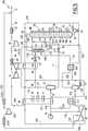
- a fifth installation 210 according to the invention is represented on the Figure 5 .
- This fifth installation 210 is intended for the implementation of a fifth method according to the invention.
- the fifth installation 210 is intended to advantageously increase the recovery of C 2 + in an existing installation including the type described in the patents US 4,157,904 and US 4,278,457 .
- the existing plant comprises the first heat exchanger 20, the first separator tank 22, the distillation column 30, the first compressor 32 coupled to the first expansion turbine 26 and the second compressor 36.
- the fifth installation 210 further comprises a second dynamic expansion turbine 40, a third compressor 41, and a downstream flask 152 for collecting the effluent from the second dynamic expansion turbine 40.
- the plant 210 further comprises an upstream heat exchanger 212, a downstream heat exchanger 214, and an auxiliary distillation column 216 provided with a bottom auxiliary pump 218.
- the fifth installation 210 also comprises a fourth compressor 220 interposed between two refrigerant 222A, 222B.
- the fifth installation 210 further comprises a downstream flask 152, disposed downstream of the second turbine 40.
- the fifth method according to the invention differs from the first method according to the invention in that the feed stream 16 is further separated into a third fraction 224 of the feed stream which is introduced into the upstream heat exchanger 212, before to be mixed with the first fraction 41A from the exchanger 20 to form the first fraction 42 cooled.
- the ratio of the molar flow rate of the third fraction 224 to the molar flow rate of the feed stream 16 is greater than 5%.
- the fifth method according to the invention differs from the first method according to the invention in that the second cooled and partially liquefied feed fraction 91A is introduced into the downstream flask 152.
- This fraction 91A is separated in the downstream flask 152 into a second liquid foot stream 154 and into a second gaseous head stream 156.
- the second liquid foot stream 154 is introduced into a fourth static expansion valve 157 to be substantially expanded under the pressure of the column 30 and form a second relaxed foot stream 158.
- the second head stream 156 coming from the downstream flask 152 is introduced into the downstream heat exchanger 214 to be cooled to a temperature below -70.degree. second cooled head stream 225.
- the second cooled overhead stream 225 is introduced into the auxiliary column 216 at a lower stage E1.
- Column 216 has a theoretical number of stages less than the number of theoretical stages of column 30. This number of stages is advantageously understood. between 1 and 7.
- the auxiliary column 216 operates at a pressure substantially equal to that of the column 30.
- the relaxed foot stream 158 obtained after expansion of the second foot stream 154 in the valve 157 is introduced into the column 30 at a level N1 advantageously corresponding to the first stage from the top of the column 30.
- a first portion 226 of the fraction 52 expanded in the valve 50 is introduced into the auxiliary column 216 at a stage E3 located above the level E1.
- a second portion 228 of the fraction 52 is introduced directly into the column 30 at the level N1, after mixing with the stream 158.
- Auxiliary column 216 produces a methane-rich head auxiliary stream 230 and a foot auxiliary current 232.
- the auxiliary head stream 230 is mixed with the methane-rich head stream 84 produced by the distillation column 30.
- Foot stream 232 is pumped by auxiliary pump 218 to form a cooled reflux stream 234 which is introduced into column 30 after mixing with stream 158.
- the stream 234 thus constitutes a cooled reflux stream which is obtained from a portion of the expanded fraction 91A resulting from the second dynamic expansion turbine 40, after separation of this effluent.
- the mixture 235 of the overhead streams 84 and 230 is separated into a first major fraction 236 of the overhead stream and a second minor fraction 238 of the overhead stream.
- the ratio of the molar flow rate of the majority fraction 236 to the minor fraction 238 is greater than 1.5.
- the majority fraction 236 is introduced successively into the second heat exchanger 28, then into the first heat exchanger 20, in order to form the heated overhead stream 86.
- the second overhead stream fraction 238 is passed through the downstream heat exchanger 214 countercurrently to the second overhead stream 156 to warm to a temperature above -50 ° C and form a second heated fraction 240. .
- the second heated fraction 240 is then separated into a return stream 242, and a compression stream 244.
- the return current 242 is reintroduced into the first head stream fraction 236, downstream of the second heat exchanger 28 and upstream of the first heat exchanger 20 to partially form the heated head stream 86.
- the recompression stream 244 is then introduced into the upstream exchanger 212 to cool the third fraction of the feed stream 224.
- the stream 244 warms to a temperature above -10 ° C to form a warmed recompression stream 246 .
- a first portion 248 of the recompression stream 246 is mixed with the first fraction of the overhead stream 86, downstream of the first heat exchanger 20 to form the heated overhead stream 87A.
- a second portion 250 of the recompression stream 246 is introduced into the third compressor 41, then into the refrigerant 222A, before being recompressed in the fourth compressor 220 and introduced into the refrigerant 222B.
- the second compressed portion 252 from the refrigerant 222B has a temperature below 60 ° C and in particular substantially equal to 40 ° C and a pressure greater than 35 bar and in particular equal to 63.1 bar.
- This first compressed portion 252 is mixed with the compressed overhead stream 90 to form the methane-rich stream 12.
- the fifth installation 210 and the fifth method according to the invention therefore make it possible to increase the C 2 + hydrocarbon recovery rate in an existing state of the art installation, without having to modify the existing equipment of the plant. installation, and in particular by keeping the heat exchangers 20 and 28, the column 30, the compressors 32, 36 and the turbine 26 identical and using the entries already present on the column 30.
- a sixth installation 270 according to the invention is represented on the Figure 6 .
- This sixth installation 270 is intended for the implementation of a sixth method according to the invention.
- the sixth method according to the invention differs from the fifth process according to the invention in that a withdrawal stream 92 is taken from the compressed methane-rich top stream 90, advantageously upstream of the point of introduction of the second compressed part. 252 in the current 90.
- the withdrawal stream 92 is reintroduced into the column 30 at a head level N14.
- the second portion 228 of the fraction 52 and the relaxed foot stream 158 are introduced into the column at a level N1 located below the N14 head level and above the N2 level.
- the pressure of the column 30 is slightly decreased.
- the presence of the new compressor 220 makes it possible to keep the power of the second compressor 36 the same despite the increase in the flow rate of the feed stream 16.
- the capacity of the first dynamic expansion turbine 26 has been kept constant.
- the second dynamic expansion turbine 40 is used to process the addition of capacity.
- auxiliary column 216 also prevents clogging of the column 30 during the flow increase.
- the sixth installation according to the invention makes it possible to maintain an ethane recovery greater than or equal to 99%, a temperature and a pressure of the feed stream 16 that are substantially identical. Similarly, the losses of charges allocated in the equipment, the efficiency of the trays in the column 30 and the position of the withdrawals, the maximum methane specification of the bottom stream 82 of the column 30, the efficiencies of the turbines and the compressors, the power of the second compressor 36 and the existing turbine 26 and the heat exchange coefficients of the existing exchangers 20 and 28 are kept identical.
- the second fraction 41B of the feed stream is taken from the first exchanger 20 and not upstream of it.
- the second fraction 41B is thus partially cooled and is partially liquefied in the first heat exchanger 20.
- the second fraction 41B issuing from the first heat exchanger 20 is then optionally introduced into an upstream separator tank 250. It is then separated in the upstream separator tank 250 in a second bottom liquid fraction 252 and in a second top gas fraction 254.
- the second bottom fraction 252 is expanded in a static expansion valve 256 to a pressure of less than 40 bar and substantially equal to the pressure of the column 30.
- the second fraction of relaxed foot 258 is then introduced into the column 30, advantageously between the level N11 and the level N8.
- the second head fraction 254 is introduced into the second dynamic expansion turbine 40 to form the second relaxed feed fraction 91A.
- This arrangement with an upstream separator tank is also applicable in the case where the feed stream 16 contains a liquid fraction.
- the installation comprises a bypass valve of a portion of the withdrawal stream 92 to divert this portion upstream of the first dynamic expansion turbine 26.
- a supplementary cooling stream is taken from the withdrawal stream obtained after passing through the first heat exchanger 20.
- the additional cooling stream is reintroduced upstream of the turbine 26, ie in the head stream 44, upstream of the balloon 22 in the cooled supply stream 42.
- the installation comprises a plurality of second exchangers 28, each being intended to receive a fraction of the overhead stream 84 and another stream.
- the overhead stream 84 is then divided into a plurality of fractions corresponding to the number of second exchangers 28.
- Each second heat exchanger 28 can then put in heat exchange only two flows each including a fraction of the overhead stream 84 and respectively, the first relaxed feed fraction 54, the second relaxed feed fraction 91A, and if necessary, the fraction column supply 46 and / or the sampling stream 92.
- a reboil stream is withdrawn from the distillation column at a sampling level.
- the reboiling current is then put in heat exchange relation with at least a part of the second expanded fraction 91A resulting from the dynamic expansion turbine 40 and optionally with the first expanded fraction 54 coming from the first turbine 26.
- This heat exchange connection can be performed within the second heat exchanger 28.
- an auxiliary expansion current is taken from the methane rich column head stream 86 from the first heat exchanger 20.
- This auxiliary expansion stream is introduced into a dynamic auxiliary expansion turbine, distinct from the first dynamic expansion turbine 26 and the second dynamic expansion turbine 40.
- the relaxed current from the auxiliary turbine is reintroduced into the methane-rich column head stream, before it passes through the first heat exchanger 20 to constitute a supplementary cooling stream of the first heat exchanger 20.
- the entire head stream 44 from the first flask 22 can form the turbine feed fraction 48.
- the method according to the invention is then devoid of separation of the overhead stream 44.
Description
La présente invention concerne un procédé de production d'un courant riche en méthane et d'un courant riche en hydrocarbures en C2 + à partir d'un courant d'alimentation contenant des hydrocarbures, selon le préambule de la revendication 1.The present invention relates to a process for producing a methane-rich stream and a C 2 + hydrocarbon-rich stream from a hydrocarbon-containing feed stream, according to the preamble of claim 1.
L'Article « Texas plant retrofit improves throughput, C2 recovery » décrit un procédé de séparation comportant deux turbines de détente dynamique en parallèle.The "Texas plant retrofit improves throughput, C2 recovery" article describes a separation process comprising two dynamic expansion turbines in parallel.
Un tel procédé est destiné à extraire des hydrocarbures en C2 +, comme notamment l'éthylène, l'éthane, le propylène, le propane et des hydrocarbures plus lourds, à partir notamment de gaz naturel, de gaz de raffinerie ou de gaz synthétique obtenu à partir d'autres sources hydrocarbonées telles que le charbon, l'huile brute, le naphta.Such a process is intended for extracting C 2 + hydrocarbons, such as, in particular, ethylene, ethane, propylene, propane and heavier hydrocarbons, especially from natural gas, refinery gas or synthetic gas. obtained from other hydrocarbon sources such as coal, crude oil, naphtha.
Le gaz naturel contient généralement une majorité de méthane et d'éthane constituant au moins 50% en moles du gaz. Il contient également en quantité plus négligeable des hydrocarbures plus lourds, tels que le propane, le butane, le pentane. Dans certains cas, il contient également de l'hélium, de l'hydrogène, de l'azote et du dioxyde de carbone.Natural gas generally contains a majority of methane and ethane constituting at least 50 mol% of the gas. It also contains in a more negligible quantity heavier hydrocarbons, such as propane, butane, pentane. In some cases, it also contains helium, hydrogen, nitrogen and carbon dioxide.
Il est nécessaire de séparer les hydrocarbures lourds du gaz naturel pour répondre à au moins deux impératifs.It is necessary to separate heavy hydrocarbons from natural gas to meet at least two requirements.
Tout d'abord, économiquement, les hydrocarbures en C2 +, et notamment l'éthane, le propane et le butane peuvent être valorisés. En outre, la demande en liquides de gaz naturel en tant que charge pour l'industrie pétrochimique augmente continûment et devrait continuer à augmenter dans les prochaines années.First of all, economically, C 2 + hydrocarbons, and in particular ethane, propane and butane, can be recovered. In addition, the demand for natural gas liquids as a burden for the petrochemical industry is growing steadily and is expected to continue to grow in the coming years.
En outre, pour des raisons de procédé, il est souhaitable de séparer les hydrocarbures lourds afin d'éviter qu'ils ne condensent au cours du transport et/ou de la manipulation des gaz. Ceci permet d'éviter des incidents tels que l'arrivée de bouchons liquides dans les installations de transport ou de traitement conçues pour des effluents gazeux.In addition, for process reasons, it is desirable to separate the heavy hydrocarbons to prevent them from condensing during transport and / or handling of the gases. This avoids incidents such as the arrival of liquid plugs in transport or treatment facilities designed for gaseous effluents.
Pour séparer les hydrocarbures en C2 + du gaz naturel, il est connu d'utiliser un procédé d'absorption à l'huile qui permet de récupérer jusqu'à 90% du propane et jusqu'à environ 40% de l'éthane.In order to separate the C 2 + hydrocarbons from natural gas, it is known to use an oil absorption process which makes it possible to recover up to 90% of the propane and up to approximately 40% of the ethane.
Pour atteindre des taux de récupération plus élevés, les procédés d'expansion cryogénique sont utilisés.To achieve higher recovery rates, cryogenic expansion methods are used.
Dans un procédé d'expansion cryogénique connu, une partie du courant d'alimentation contenant les hydrocarbures est utilisée pour les rebouilleurs secondaires d'une colonne de séparation du méthane.In a known cryogenic expansion process, a portion of the hydrocarbon feed stream is used for the secondary reboilers of a methane separation column.
Puis, les différents effluents, après condensation partielle, sont combinés pour alimenter un séparateur gaz-liquide.Then, the different effluents, after partial condensation, are combined to feed a gas-liquid separator.
Comme décrit dans
Ce procédé présente l'avantage d'être facile à démarrer et d'offrir une flexibilité opératoire importante, combinée à une bonne efficacité et à une bonne sûreté.This method has the advantage of being easy to start and offer significant operational flexibility, combined with good efficiency and good safety.
Toutefois, les contraintes économiques nécessitent d'augmenter encore l'efficacité du procédé tout en conservant un rendement d'extraction d'éthane très élevé. Il est en outre nécessaire de minimiser l'encombrement des installations et de réduire, voire de supprimer l'apport en réfrigérants externes tels que le propane, notamment pour la mise en oeuvre du procédé sur des installations flottantes ou dans des zones sensibles en terme de sécurité.However, the economic constraints require to further increase the efficiency of the process while maintaining a very high ethane extraction yield. It is also necessary to minimize the size of the installations and to reduce or even eliminate the supply of external refrigerants such as propane, especially for the implementation of the process on floating installations or in sensitive areas in terms of security.
Un but de l'invention est donc d'obtenir un procédé de production qui permet de séparer un courant d'alimentation contenant des hydrocarbures en un courant riche en hydrocarbures en C2 + et en un courant riche en méthane, de manière très économique, peu encombrante et très efficace.An object of the invention is therefore to obtain a production process which makes it possible to separate a feed stream containing hydrocarbons in a stream rich in C 2 + hydrocarbons and in a stream rich in methane, very economically, compact and very efficient.
A cet effet, l'invention a pour objet un procédé selon la revendication 1.For this purpose, the subject of the invention is a method according to claim 1.
Le procédé selon l'invention peut comprendre l'une ou plusieurs des caractéristiques des revendications 2 à 13 ou la caractéristique suivante:
- la température de la partie de la deuxième fraction du courant d'alimentation introduite dans la deuxième turbine de détente dynamique est supérieure à la température de la fraction d'alimentation de turbine introduite dans la première turbine de détente dynamique ;
- the temperature of the portion of the second fraction of the feed stream introduced into the second dynamic expansion turbine is greater than the temperature of the turbine feed fraction introduced into the first dynamic expansion turbine;
L'invention a en outre pour objet une installation de production d'un courant riche en méthane et d'un courant riche en hydrocarbures en C2 + à partir d'un courant d'alimentation contenant des hydrocarbures, selon la revendication 14.The invention further relates to a plant for producing a methane-rich stream and a stream rich in C 2 + hydrocarbons from a feed stream containing hydrocarbons according to
L'installation selon l'invention peut comprendre la caractéristique de la revendication 15.The plant according to the invention may comprise the feature of claim 15.
L'invention sera mieux comprise à la lecture de la description qui va suivre, donnée uniquement à titre d'exemple, et faite en se référant aux dessins annexés sur lesquels :
- la
Figure 1 est un schéma synoptique fonctionnel d'une première installation de production destinée à la mise en oeuvre d'un premier procédé selon l'invention ; - la
Figure 2 est un schéma synoptique fonctionnel d'une deuxième installation de production destinée à la mise en oeuvre d'un deuxième procédé selon l'invention ; - la
Figure 3 est un schéma synoptique fonctionnel d'une troisième installation de production destinée à la mise en oeuvre d'un cinquième procédé selon l'invention ; - la
Figure 4 est un schéma synoptique fonctionnel d'une quatrième installation de production destinée à la mise en oeuvre d'un sixième procédé selon l'invention ; - la
Figure 5 est un schéma synoptique fonctionnel d'une cinquième installation de production destinée à la mise en oeuvre d'un septième procédé selon l'invention ; - la
Figure 6 est un schéma synoptique fonctionnel d'une sixième installation de production destinée à la mise en oeuvre d'un huitième procédé selon l'invention.
- the
Figure 1 is a functional block diagram of a first production facility for carrying out a first method according to the invention; - the
Figure 2 is a functional block diagram of a second production facility for carrying out a second method according to the invention; - the
Figure 3 is a functional block diagram of a third production facility for carrying out a fifth method according to the invention; - the
Figure 4 is a functional block diagram of a fourth production facility for carrying out a sixth method according to the invention; - the
Figure 5 is a functional block diagram of a fifth production facility for carrying out a seventh method according to the invention; - the
Figure 6 is a functional block diagram of a sixth production facility for carrying out an eighth method according to the invention.
Dans tout ce qui suit, on désignera par les mêmes références un courant circulant dans une conduite et la conduite qui le transporte.In all that follows, we will designate by the same references a current flowing in a pipe and the pipe that carries it.
En outre, sauf indication contraire, les pourcentages cités sont des pourcentages molaires et les pressions sont données en bars absolus.In addition, unless otherwise indicated, the percentages mentioned are molar percentages and the pressures are given in absolute bar.
Dans les exemples simulés numériquement, le rendement de chaque compresseur est choisi comme étant de 82% polytropique et le rendement de chaque turbine est de 85% adiabatique.In the numerically simulated examples, the efficiency of each compressor is selected to be 82% polytropic and the efficiency of each turbine is 85% adiabatic.
De même, les colonnes de distillation décrites utilisent des plateaux mais elles peuvent également utiliser du garnissage vrac ou structuré. Une combinaison de plateaux et de garnissage est également possible. Les turbines additionnelles décrites entraînent des compresseurs mais elles peuvent également entraîner des générateurs électriques à fréquence variable dont l'électricité produite peut être utilisée dans le réseau par l'intermédiaire d'un convertisseur de fréquence. Les courants dont la température est supérieure à l'ambiante sont décrits comme étant refroidis par des aéro-réfrigérants. En variante, il est possible d'utiliser des échangeurs à eau par exemple à eau douce ou à eau de mer.Similarly, the described distillation columns use trays but they can also use loose packing or structured. A combination of trays and packing is also possible. The additional turbines described involve compressors but they can also cause variable frequency electric generators whose electricity produced can be used in the network via a frequency converter. Currents with a temperature above ambient are described as being cooled by aero-refrigerants. Alternatively, it is possible to use water exchangers for example freshwater or seawater.
La
Le courant gazeux 16 est un courant de gaz naturel, un courant de gaz de raffinerie, ou un courant de gaz synthétique obtenu à partir d'une source hydrocarbonée telle que du charbon, de l'huile brute, du naphta. Dans l'exemple représenté sur les Figures, le courant 16 est un courant de gaz naturel déshydraté.The
Le procédé et l'installation 10 s'appliquent avantageusement à la construction d'une nouvelle unité de récupération de méthane et d'éthane.The method and the
L'installation 10 comprend, d'amont en aval, un premier échangeur thermique 20, un premier ballon séparateur 22 et une première turbine de détente dynamique 26, propre à produire du travail lors de la détente d'un courant passant à travers la turbine.The
Selon l'invention, l'installation 10 comprend en outre un deuxième échangeur thermique 28, une première colonne de distillation 30, un premier compresseur 32 accouplé à la première turbine de détente dynamique 26, un premier réfrigérant 34, un deuxième compresseur 36, un deuxième réfrigérant 38, et une pompe de fond de colonne 39.According to the invention, the
Selon l'invention, l'installation 10 comprend en outre une deuxième turbine de détente dynamique 40 et un troisième compresseur 41 accouplé à la deuxième turbine de détente dynamique 40.According to the invention, the
Un premier procédé de production selon l'invention, mis en oeuvre dans l'installation 10 va maintenant être décrit.A first production method according to the invention, implemented in the
A titre d'exemple, le courant d'alimentation 16 est formé d'un gaz naturel déshydraté qui comprend, en moles, 2,06% d'azote, 83,97% de méthane, 6,31% d'éthane, 3,66% de propane, 0,70% d'isobutane, 1,50% de n-butane, 0,45% d'isopentane, 0,83% de n-pentane et 0,51% de dioxyde de carbone.By way of example, the
Le courant d'alimentation 16 présente plus généralement en moles entre 5 % et 15 % d'hydrocarbures en C2 + à extraire et entre 75 % et 90 % de méthane.The
Par « gaz déshydraté », on entend un gaz dont la teneur en eau est la plus basse possible et est notamment inférieure à 1 ppm.The term "dehydrated gas" means a gas whose water content is as low as possible and is especially less than 1 ppm.
Le courant d'alimentation 16 présente une pression supérieure à 35 bars, notamment supérieure à 50 bars et une température voisine de la température ambiante et notamment sensiblement égale à 30 °C. Le débit du courant d'alimentation est dans cet exemple de 15 000 kmoles/heure.The
Le courant d'alimentation 16 est tout d'abord divisé en une première fraction 41A de courant d'alimentation et en une deuxième fraction 41B de courant d'alimentation.The
Le rapport du débit molaire de la première fraction 41A à la deuxième fraction 41B est par exemple supérieur à 2 et est notamment compris entre 2 et 15.The ratio of the molar flow rate of the
Dans l'exemple représenté, la première fraction 41A est introduite dans le premier échangeur thermique 20 où elle est refroidie et partiellement condensée pour former une fraction 42 de courant d'alimentation refroidi.In the example shown, the
La température de la fraction 42 est inférieure à -10°C et est notamment égale à - 26,7°C. Puis, la fraction refroidie 42 est introduite dans le premier ballon séparateur 22.The temperature of the
La teneur en liquide de la fraction refroidie 42 est inférieure à 50% molaire.The liquid content of the cooled
Un courant léger de tête 44 gazeux et un courant lourd de pied 45 liquide sont extraits du premier ballon séparateur 22.A
Dans cet exemple, le courant gazeux 44 est divisé en une fraction minoritaire 46 d'alimentation de colonne et en une fraction majoritaire 48 d'alimentation de turbine. Le rapport du débit molaire de la fraction majoritaire 48 à la fraction minoritaire 46 est supérieur à 2.In this example, the
La fraction d'alimentation de colonne 46 est introduite dans le deuxième échangeur thermique 28 pour y être totalement liquéfiée et sous-refroidie. Elle forme une fraction d'alimentation de colonne refroidie 49. Cette fraction 49 est détendue dans une première vanne de détente statique 50 pour former une fraction détendue 52 introduite en reflux dans la première colonne de distillation 30.The
La température de la fraction détendue 52 obtenue après passage dans la vanne 50 est inférieure à -70°C et est notamment égale à -111°C.The temperature of the expanded
La pression de la fraction détendue 52 est en outre sensiblement égale à la pression d'opération de la colonne 30 qui est inférieure à 40 bars et notamment comprise entre 10 bars et 30 bars, avantageusement égale à 17 bars.The pressure of the expanded
La fraction 52 est introduite dans une partie haute de la colonne 30 à un niveau N1, situé au premier étage en partant du haut de la colonne 30.The
La fraction d'alimentation de turbine 48 est introduite dans la première turbine de détente dynamique 26. Elle subit une expansion dynamique jusqu'à une pression P1 proche de la pression d'opération de la colonne 30 pour former une première fraction d'alimentation détendue 54 qui présente une température inférieure à -50°C, notamment égale à -79°C.The
L'expansion de la fraction d'alimentation 48 dans la première turbine 26 permet de récupérer 3574 kW d'énergie qui refroidissent la fraction 48.The expansion of the
La première fraction détendue 54, qui est l'effluent issu de la première turbine 26 de détente dynamique constitue un premier courant de reflux refroidi 56.The first expanded
La teneur en liquide du courant de reflux refroidi 56 est supérieure à 5% molaire.The liquid content of the cooled
Le courant de reflux refroidi 56 est introduit dans une partie moyenne de la colonne 30 située sous la partie supérieure, à un niveau N2 inférieur au niveau N1, et correspondant dans cet exemple au sixième étage en partant du haut de la colonne 30.The cooled
Le courant lourd liquide 45 récupéré au fond du premier ballon séparateur 22 est détendu dans une deuxième vanne de détente statique 58 pour former un courant lourd détendu 60.The heavy
La pression du courant lourd détendu 60 est inférieure à 50 bars et est notamment sensiblement égale à la pression de la colonne 30. La température du courant lourd détendu 60 est inférieure à -30°C et est notamment sensiblement égale à - 48°C.The pressure of the expanded
Le courant lourd liquide 45 est introduit en totalité dans la colonne 30 après sa détente dans la vanne 58, sans passer par le premier échangeur thermique 20. Ainsi, le courant lourd liquide 45 avant son passage dans la vanne 58 et le courant lourd détendu 60 n'entrent pas en relation d'échange thermique avec le courant d'alimentation 16, ni avec les fractions 41A, 41B de ce courant d'alimentation 16.The heavy
En particulier, le courant lourd 45 ne passe pas dans l'échangeur thermique 20 entre la sortie du ballon 22 et l'entrée de la colonne 30.In particular, the heavy current 45 does not pass into the
Un premier courant de rebouillage 74 est prélevé au voisinage du fond de la colonne 30 à une température supérieure à -3°C et notamment sensiblement égale à 9,6°C, à un niveau N6 situé sous le niveau N3, avantageusement au vingt-et-unième étage en partant du haut de la colonne 30.A
Le premier courant 74 est amené jusqu'au premier échangeur thermique 20 où il est réchauffé jusqu'à une température supérieure à 3°C et notamment égale à 16,3°C avant d'être renvoyé à un niveau N7 correspondant au vingt-deuxième étage en partant du haut de la colonne 30.The
Un deuxième courant de rebouillage 76 est prélevé à un niveau N8 situé au-dessus du niveau N6 et en dessous du niveau N3, avantageusement au dix-septième étage en partant du haut de la colonne. Le deuxième courant de rebouillage 76 est introduit dans le premier échangeur thermique 20 pour y être réchauffé jusqu'à une température supérieure à -8°C et notamment égale à - 4,1°C. Il est ensuite renvoyé dans la colonne 30 à un niveau N9 situé sous le niveau N8 et au-dessus du niveau N6, avantageusement au dix-huitième étage en partant du haut de la colonne 30.A
Un troisième courant de rebouillage 78 est prélevé à un niveau N10 situé sous le niveau N3 et au-dessus du niveau N8, avantageusement au treizième étage en partant du haut de la colonne 30. Le troisième courant de rebouillage 78 est ensuite amené jusqu'au premier échangeur thermique 20 où il est réchauffé jusqu'à une température supérieure à -30°C et notamment égale à -19°C avant d'être renvoyé à un niveau N11 de la colonne 30 situé sous le niveau N10 et situé au-dessus du niveau N8, avantageusement au quatorzième étage en partant du haut de la colonne 30.A third reboiling current 78 is taken at a level N10 located below the level N3 and above the level N8, advantageously at the thirteenth stage starting from the top of the
Ainsi, le courant 52 est introduit dans la partie haute de la colonne 30 qui s'étend à partir d'une hauteur supérieure à 35% de la hauteur de la colonne 30, alors que le courant 60 est introduit dans une partie moyenne qui s'étend sous la partie haute.Thus, the
La colonne 30 produit en pied un courant liquide 82 de fond de colonne. Le courant 82 de fond de colonne présente une température supérieure à 4°C et notamment égale à 16,3°C.The
Ainsi, le courant de fond 82 contient en mole 1,17% de dioxyde de carbone, 0,00% d'azote, 0,43% de méthane, 42,89% d'éthane, 28,40% de propane, 5,51% de i-butane, 11,66% de n-butane, 3,47% de i-pentane, 6,46% de n-pentane.Thus, the
Plus généralement, le courant 82 a un rapport C1/C2 inférieur à 3% molaire, par exemple égal à 1%.More generally, the
Le courant 82 contient plus de 80%, avantageusement plus de 87% en moles de l'éthane contenu dans le courant d'alimentation 16 et il contient sensiblement 100% en moles des hydrocarbures en C3 + contenus dans le courant d'alimentation 16.The
Le courant de fond de colonne 82 est pompé dans la pompe 39 pour former la coupe 14 riche en hydrocarbures en C2 +.The
Il peut être avantageusement réchauffé par mise en relation d'échange thermique avec au moins une fraction du courant d'alimentation 16 jusqu'à une température inférieure à sa température de bulle, pour le maintenir sous forme liquide.It can be advantageously heated by placing in heat exchange relation with at least a fraction of the
La colonne 30 produit en tête un courant gazeux 84 de tête de colonne riche en méthane. Le courant 84 présente une température inférieure à -70°C et notamment sensiblement égale à -105°C. Il présente une pression sensiblement égale à la pression de la colonne 30, par exemple égale à 17,0 bars.The
Le courant de tête 84 est successivement introduit dans le deuxième échangeur thermique 28, puis dans le premier échangeur thermique 20 pour y être réchauffé et former un courant 86 de tête riche en méthane réchauffé. Le courant 86 présente une température supérieure à -10°C et notamment égale à 22,9°C.The
A la sortie du premier échangeur 20, le courant 86 est divisé en une première fraction du courant de tête réchauffé 87A et en une deuxième fraction du courant de tête réchauffé 87B.At the outlet of the
Le rapport du débit molaire de la première fraction 87A au débit molaire de la deuxième fraction 87B est supérieur à 2 et est notamment par exemple compris entre 2 et 5.The ratio of the molar flow rate of the
La première fraction 87A est introduite dans le premier compresseur 32 entraîné par la turbine principale 26 pour y être comprimée à une pression supérieure à 20 bars.The
La deuxième fraction 87B est introduite dans le troisième compresseur 41 pour être comprimée à une pression supérieure à 20 bars et sensiblement égale à la pression à laquelle est comprimée la première fraction 87A dans le premier compresseur 32.The
Puis, les fractions 87A, 87B comprimées issues respectivement des compresseurs 32, 41 sont réunies avant d'être introduites dans le premier réfrigérant à air 34. Les fractions réunies 87A, 87B y sont refroidies à une température inférieure à 60°C, notamment à la température ambiante.Then, the
Le courant 88 comprimé ainsi obtenu est introduit dans le deuxième compresseur 36 puis dans le deuxième réfrigérant 38 pour former un courant de tête 90 comprimé.The compressed
Le courant 90 présente ainsi une pression supérieure à 40 bars et notamment sensiblement égale à 63,1 bars.The current 90 thus has a pressure greater than 40 bars and in particular substantially equal to 63.1 bars.
Le courant de tête de colonne comprimé 90 forme le courant riche en méthane 12 produit par le procédé selon l'invention.The compressed
Sa composition est avantageusement de 96,28% molaire de méthane, 2,37% molaire d'azote et 0,92% molaire d'éthane. Il comprend plus de 99,93% du méthane contenu dans le courant d'alimentation 16 et moins de 5% des hydrocarbures en C2 + contenus dans le courant d'alimentation 16.Its composition is advantageously 96.28 mol% of methane, 2.37 mol% of nitrogen and 0.92 mol% of ethane. It comprises more than 99.93% of the methane contained in the
La deuxième fraction 41B du courant d'alimentation 16 est introduite dans la deuxième turbine de détente dynamique 40 pour être détendue à une deuxième pression P2 sensiblement égale à la pression de la colonne 30 et former ainsi une deuxième fraction d'alimentation détendue 91A.The
La température de la deuxième fraction 41B alimentant la deuxième turbine de détente dynamique 40 est supérieure à la température de la fraction d'alimentation de turbine 48 alimentant la première turbine de détente dynamique 26, par exemple d'au moins 30 °C.The temperature of the
Par ailleurs, la deuxième pression P2 est sensiblement égale à la première pression P1. La différence entre la pression P1 et la pression P2 est inférieure à 8 bars, avantageusement inférieure à 5 bars et en particulier inférieure à 2 bars.Moreover, the second pressure P2 is substantially equal to the first pressure P1. The difference between the pressure P1 and the pressure P2 is less than 8 bar, advantageously less than 5 bar and in particular less than 2 bar.
La deuxième fraction détendue 91A présente ainsi une température inférieure à 0°C et notamment de l'ordre de - 25°C.The
Puis, la deuxième fraction 91A est introduite dans le deuxième échangeur thermique 28 pour y être refroidie à une température inférieure à -70°C et notamment égale à - 102,5°C et pour y être partiellement condensée, par échange thermique avec le courant de tête 84 et éventuellement, avec la fraction d'alimentation de colonne 46, lorsqu'elle est présente.Then, the
La deuxième fraction détendue 91B issue du deuxième échangeur thermique 28 forme un deuxième courant de reflux qui est convoyé jusqu'à la colonne 30 pour y être introduit dans la partie supérieure à un niveau N12 situé par exemple entre le niveau N1 et le niveau N2, au quatrième étage en partant du haut de la colonne.The second expanded
Des exemples de températures, de pressions, et de débits molaires des différents courants sont donnés dans le Tableau 1 ci-dessous.
Le Tableau 2 ci-dessous illustre la puissance consommée par le compresseur 36 en fonction du débit de la deuxième fraction 41B envoyée vers la deuxième turbine 40.
La consommation énergétique du procédé selon l'invention, constituée par l'énergie d'entraînement du deuxième compresseur 36, est de 12244 kW, contre 14111 kW avec un procédé de l'état de la technique selon
Par rapport à l'état de la technique, le procédé selon l'invention permet donc d'obtenir une réduction significative de la puissance consommée, tout en conservant une forte sélectivité pour l'extraction d'éthane.Compared with the state of the art, the method according to the invention thus makes it possible to obtain a significant reduction in the power consumed, while maintaining a high selectivity for the extraction of ethane.
Une deuxième installation 110 selon l'invention est représentée sur la
Le deuxième procédé diffère du premier procédé en ce qu'un courant de soutirage 92 est prélevé dans le courant de tête comprimé 90.The second method differs from the first method in that a
Le courant de soutirage 92 présente un débit molaire non nul compris entre 0 % et 35 % du débit molaire du courant de tête comprimé 90 en amont du prélèvement, le reste du courant de tête comprimé 90 formant le courant 12.The
Le courant de soutirage 92 est refroidi successivement dans le premier échangeur 20, puis dans le deuxième échangeur 28, avant d'être détendu dans une troisième vanne de détente statique 94.The
Le courant 96, qui avant détente dans la vanne 94, est essentiellement liquide, possède après détente une fraction liquide supérieure à 0,8.The current 96, which before expansion in the
Le courant de soutirage détendu 96 issu de la troisième vanne 94 est ensuite introduit en reflux au voisinage de la tête de la colonne 30 à un niveau N14 situé au-dessus du niveau N1 et correspondant avantageusement au premier étage de la colonne 30.The expanded
La température du courant de soutirage détendu 96 avant son introduction dans la colonne 30 est inférieure à -70°C et est avantageusement égale à -113,5°C.The temperature of the expanded
Des exemples de températures, de pressions et de débits molaires des différents courants sont donnés dans le Tableau 3 ci-dessous.
Dans une variante (non représentée), le deuxième compresseur 36 peut comprendre deux étages de compression séparés par un aéro-réfrigérant.In a variant (not shown), the
La puissance consommée par le compresseur 36 (mono-étagé) en fonction du débit de la deuxième fraction de courant d'alimentation 41B est donnée dans le tableau 4 ci-après.
Le deuxième procédé selon l'invention permet donc d'obtenir des taux de récupération d'éthane extrêmement élevés, supérieurs à 90%, et notamment supérieurs à 99%. Cette récupération quasi-totale de l'éthane contenu dans le courant d'alimentation 16 peut être obtenue comme dans le procédé décrit dans
Une troisième installation 170 selon l'invention est représentée sur la
La troisième installation 170 est destinée à la mise en oeuvre d'un troisième procédé selon l'invention.The
Le troisième procédé selon l'invention diffère du premier procédé selon l'invention en ce que la fraction d'alimentation détendue 54 destinée à la colonne 30 est introduite au moins partiellement dans le deuxième échangeur thermique 28 pour y être mise en relation d'échange thermique avec le courant gazeux 84 de tête de colonne riche en méthane, avec la deuxième fraction d'alimentation détendue 91A issue de la deuxième turbine de détente dynamique 40, et avantageusement avec la fraction d'alimentation de colonne 46, lorsque celle-ci est présente.The third method according to the invention differs from the first method according to the invention in that the
La fraction 54 est ainsi refroidie jusqu'à une température inférieure à - 60°C, et notamment sensiblement égale à - 84°C. Elle est au moins partiellement condensée pour former le premier courant de reflux refroidi 56.The
Le courant de reflux refroidi 56 est alors introduit dans la partie moyenne de la colonne 30 au niveau N2, comme décrit précédemment.The cooled
Une dérivation peut être prévue pour introduire une partie de la fraction détendue 54 dans la colonne 30 sans passer par l'échangeur 28.A bypass may be provided to introduce a portion of the expanded
Des exemples de températures, de pressions et de débits molaires des différents courants sont donnés dans le Tableau 5 ci-après.
Une quatrième installation 180 selon l'invention est représentée sur la
Le quatrième procédé selon l'invention diffère du troisième procédé selon l'invention, représenté sur la
Le quatrième procédé selon l'invention est par ailleurs analogue au troisième procédé selon l'invention.The fourth method according to the invention is moreover analogous to the third method according to the invention.
Une cinquième installation 210 selon l'invention est représentée sur la
La cinquième installation 210 est destinée à avantageusement augmenter la récupération des C2 + dans une installation existante notamment du type décrit dans les brevets
L'installation existante comprend le premier échangeur thermique 20, le premier ballon séparateur 22, la colonne de distillation 30, le premier compresseur 32 accouplé à la première turbine de détente 26 et le deuxième compresseur 36.The existing plant comprises the
La cinquième installation 210 selon l'invention comprend en outre une deuxième turbine de détente dynamique 40, un troisième compresseur 41, et un ballon aval 152 pour recueillir l'effluent de la deuxième turbine de détente dynamique 40.The
L'installation 210 comprend de plus un échangeur thermique amont 212, un échangeur thermique aval 214, et une colonne auxiliaire de distillation 216 munie d'une pompe auxiliaire de fond 218.The
La cinquième installation 210 comprend également un quatrième compresseur 220 interposé entre deux aéro-réfrigérants 222A, 222B.The
La cinquième installation 210 comprend en outre un ballon aval 152, disposé en aval de la deuxième turbine 40.The
Le cinquième procédé selon l'invention diffère du premier procédé selon l'invention en ce que le courant d'alimentation 16 est en outre séparé en une troisième fraction 224 du courant d'alimentation qui est introduite dans l'échangeur thermique amont 212, avant d'être mélangée avec la première fraction 41A issue de l'échangeur 20 pour former la première fraction 42 refroidie.The fifth method according to the invention differs from the first method according to the invention in that the
Le rapport du débit molaire de la troisième fraction 224 au débit molaire du courant d'alimentation 16 est supérieur à 5%.The ratio of the molar flow rate of the
Ainsi, le cinquième procédé selon l'invention diffère du premier procédé selon l'invention en ce que la deuxième fraction d'alimentation 91A refroidie et partiellement liquéfiée est introduite dans le ballon aval 152.Thus, the fifth method according to the invention differs from the first method according to the invention in that the second cooled and partially liquefied
Cette fraction 91A est séparée dans le ballon aval 152 en un deuxième courant de pied liquide 154 et en un deuxième courant de tête gazeux 156.This
Le deuxième courant de pied liquide 154 est introduit dans une quatrième vanne de détente statique 157 pour y être détendu sensiblement à la pression de la colonne 30 et former un deuxième courant de pied détendu 158.The second
A la différence du premier procédé selon l'invention décrit plus haut, le deuxième courant de tête 156 issu du ballon aval 152 est introduit dans l'échangeur thermique aval 214 pour y être refroidi à une température inférieure à -70°C et former un deuxième courant de tête refroidi 225.Unlike the first method according to the invention described above, the
Le deuxième courant de tête refroidi 225 est introduit dans la colonne auxiliaire 216 à un étage inférieur E1.The second cooled
La colonne 216 présente un nombre d'étages théoriques inférieur au nombre d'étages théoriques de la colonne 30. Ce nombre d'étages est avantageusement compris entre 1 et 7. La colonne auxiliaire 216 opère à une pression sensiblement égale à celle de la colonne 30.
Le courant de pied détendu 158 obtenu après détente du deuxième courant de pied 154 dans la vanne 157 est introduit dans la colonne 30 à un niveau N1 correspondant avantageusement au premier étage depuis le haut de la colonne 30.The
Une première partie 226 de la fraction 52 détendue dans la vanne 50 est introduite dans la colonne auxiliaire 216 à un étage E3 situé au-dessus du niveau E1. Une deuxième partie 228 de la fraction 52 est introduite directement dans la colonne 30 au niveau N1, après mélange avec le courant 158.A
La colonne auxiliaire 216 produit un courant auxiliaire de tête 230 riche en méthane et un courant auxiliaire de pied 232.
Le courant auxiliaire de tête 230 est mélangé au courant de tête 84 riche en méthane produit par la colonne de distillation 30.The
Le courant de pied 232 est pompé par la pompe auxiliaire 218 pour former un courant de reflux refroidi 234 qui est introduit dans la colonne 30 après mélange avec le courant 158.
Le courant 234 constitue donc un courant de reflux refroidi qui est obtenu à partir d'une partie de la fraction détendue 91A issue de la deuxième turbine de détente dynamique 40, après séparation de cet effluent.The
Le mélange 235 des courants de tête 84 et 230 est séparé en une première fraction majoritaire 236 de courant de tête et en une deuxième fraction minoritaire 238 de courant de tête.The
Le rapport du débit molaire de la fraction majoritaire 236 à la fraction minoritaire 238 est supérieur à 1,5.The ratio of the molar flow rate of the
La fraction majoritaire 236 est introduite successivement dans le deuxième échangeur thermique 28, puis dans le premier échangeur thermique 20, afin de former le courant de tête réchauffé 86.The
La deuxième fraction 238 de courant de tête est passée dans l'échangeur thermique aval 214 à contre-courant du deuxième courant de tête 156 pour s'y réchauffer jusqu'à une température supérieure à -50°C et former une deuxième fraction réchauffée 240.The second
La deuxième fraction réchauffée 240 est ensuite séparée en un courant de retour 242, et en un courant de compression 244.The second
Le courant de retour 242 est réintroduit dans la première fraction 236 de courant de tête, en aval du deuxième échangeur 28 et en amont du premier échangeur 20 pour former en partie le courant de tête 86 réchauffé.The return current 242 is reintroduced into the first
Le courant de recompression 244 est ensuite introduit dans l'échangeur amont 212 pour refroidir la troisième fraction du courant d'alimentation 224. Le courant 244 se réchauffe jusqu'à une température supérieure à -10°C pour former un courant de recompression réchauffé 246.The
Une première partie 248 du courant de recompression 246 est mélangée à la première fraction du courant de tête 86, en aval du premier échangeur thermique 20 pour former le courant de tête réchauffé 87A.A
Une deuxième partie 250 du courant de recompression 246 est introduite dans le troisième compresseur 41, puis dans l'aéro-réfrigérant 222A, avant d'être recomprimée dans le quatrième compresseur 220 et d'être introduite dans l'aéro-réfrigérant 222B.A
La deuxième partie comprimée 252 issue de l'aéro-réfrigérant 222B présente une température inférieure à 60°C et notamment sensiblement égale à 40°C et une pression supérieure à 35 bars et notamment égale à 63,1 bars.The second
Cette première partie comprimée 252 est mélangée avec le courant de tête comprimé 90 pour former le courant riche en méthane 12.This first
La cinquième installation 210 et le cinquième procédé selon l'invention permettent donc d'augmenter le taux de récupération d'hydrocarbures en C2 + dans une installation de l'état de la technique existante, sans avoir à modifier les équipements existants de l'installation, et notamment en conservant les échangeurs thermiques 20 et 28, la colonne 30, les compresseurs 32, 36 et la turbine 26 identiques et en utilisant les entrées déjà présentes sur la colonne 30.The
Pour conserver les équipements existants intacts et améliorer la récupération en C2 +, la pression de la colonne 30 a été légèrement diminuée. Sans contre-mesure, cette diminution aurait entraîné l'augmentation de la puissance du compresseur 36.To preserve the existing equipment intact and improve the C 2 + recovery, the pressure of the
Toutefois, l'ajout du compresseur 220 permet de pallier ce problème. En outre, le débit à travers la turbine 26 existante et sa puissance n'ont pas été augmentés par rapport à l'unité existante.However, the addition of the
Cette installation permet néanmoins d'obtenir, avec un excellent rendement, une récupération d'éthane très supérieure à celle observée dans l'état de la technique.This installation nevertheless makes it possible to obtain, with an excellent yield, a recovery of ethane much higher than that observed in the state of the art.
Une sixième installation 270 selon l'invention est représentée sur la
Le sixième procédé selon l'invention diffère du cinquième procédé selon l'invention en ce qu'un courant de soutirage 92 est prélevé dans le courant de tête riche en méthane comprimé 90, avantageusement en amont du point d'introduction de la deuxième partie comprimée 252 dans le courant 90.The sixth method according to the invention differs from the fifth process according to the invention in that a
Le courant de soutirage 92 est réintroduit dans la colonne 30 à un niveau N14 de tête. A la différence du cinquième procédé selon l'invention, la deuxième partie 228 de la fraction 52 et le courant de pied détendu 158 sont introduits dans la colonne à un niveau N1 situé sous le niveau de tête N14 et au-dessus du niveau N2.The
La mise en oeuvre du sixième procédé selon l'invention est par ailleurs analogue à celle du cinquième procédé selon l'invention.The implementation of the sixth method according to the invention is moreover analogous to that of the fifth method according to the invention.
Pour conserver la récupération en C2 + de l'unité existante, la pression de la colonne 30 est légèrement diminuée. La présence du nouveau compresseur 220 permet de conserver identique la puissance du deuxième compresseur 36, malgré l'augmentation de débit du courant d'alimentation 16.To maintain the C 2 + recovery of the existing unit, the pressure of the
En outre, la capacité de la première turbine de détente dynamique 26 a été conservée constante. La deuxième turbine de détente dynamique 40 est utilisée pour traiter l'ajout de capacité.In addition, the capacity of the first
La présence d'une colonne auxiliaire 216 permet également d'éviter l'engorgement de la colonne 30 lors de l'augmentation de débit.The presence of an
La sixième installation selon l'invention permet de conserver une récupération d'éthane supérieure ou égale à 99%, une température et une pression du courant d'alimentation 16 sensiblement identiques. De même, les pertes de charges allouées dans les équipements, l'efficacité des plateaux dans la colonne 30 et la position des soutirages, la spécification maximale en méthane du courant de fond 82 de la colonne 30, les efficacités des turbines et des compresseurs, la puissance du deuxième compresseur 36 et de la turbine 26 existante et les coefficients d'échanges thermiques des échangeurs existants 20 et 28 sont conservés identiques.The sixth installation according to the invention makes it possible to maintain an ethane recovery greater than or equal to 99%, a temperature and a pressure of the
Dans une variante qui n'est pas couverte par la présente invention (représentée en pointillés sur la
La deuxième fraction 41B issue du premier échangeur thermique 20 est alors éventuellement introduite dans un ballon séparateur amont 250. Elle est alors séparée dans le ballon séparateur amont 250 en une deuxième fraction liquide de pied 252 et en une deuxième fraction gazeuse de tête 254. La deuxième fraction de pied 252 est détendue dans une vanne de détente statique 256 jusqu'à une pression inférieure à 40 bars et sensiblement égale à la pression de la colonne 30.The
La deuxième fraction de pied détendue 258 est ensuite introduite dans la colonne 30, avantageusement entre le niveau N11 et le niveau N8.The second fraction of
La deuxième fraction de tête 254 est introduite dans la deuxième turbine de détente dynamique 40 pour former la deuxième fraction d'alimentation détendue 91A.The
Cette disposition avec un ballon séparateur amont s'applique aussi au cas où le courant d'alimentation 16 contient une fraction liquide.This arrangement with an upstream separator tank is also applicable in the case where the
Dans une autre variante (non représentée) des modes de réalisation des
Dans cette variante de procédé, un courant de refroidissement d'appoint est prélevé dans le courant de soutirage obtenu après son passage dans le premier échangeur thermique 20. Le courant de refroidissement d'appoint est réintroduit en amont de la turbine 26, soit dans le courant de tête 44, soit en amont du ballon 22 dans le courant d'alimentation refroidi 42.In this variant of the process, a supplementary cooling stream is taken from the withdrawal stream obtained after passing through the
Dans une autre variante (non représentée) des modes de réalisation des
Le courant de tête 84 est alors divisé en une pluralité de fractions correspondant au nombre de deuxièmes échangeurs 28.The
Chaque deuxième échangeur 28 peut alors mettre en échange thermique uniquement deux flux incluant chacun une fraction du courant de tête 84 et respectivement, la première fraction d'alimentation détendue 54, la deuxième fraction d'alimentation détendue 91A, et le cas échéant, la fraction d'alimentation de colonne 46 et/ou le courant de prélèvement 92.Each
Dans une autre variante (non représentée) des modes de réalisation des
Cette mise en relation d'échange thermique peut être effectuée au sein du deuxième échangeur thermique 28.This heat exchange connection can be performed within the
Dans encore une autre variante (non représentée), un courant de détente auxiliaire est prélevé dans le courant de tête de colonne riche en méthane 86 issu du premier échangeur thermique 20. Ce courant de détente auxiliaire est introduit dans une turbine auxiliaire de détente dynamique, distincte de la première turbine de détente dynamique 26 et de la deuxième turbine de détente dynamique 40. Le courant détendu issu de la turbine auxiliaire est réintroduit dans le courant de tête de colonne riche en méthane, avant son passage dans le premier échangeur thermique 20 pour constituer un courant de refroidissement d'appoint du premier échangeur thermique 20.In yet another variant (not shown), an auxiliary expansion current is taken from the methane rich
Plus généralement, la totalité du courant de tête 44 issu du premier ballon 22 peut former la fraction 48 d'alimentation de turbine. Le procédé selon l'invention est alors dépourvu de séparation du courant de tête 44.More generally, the
Claims (15)
- A method for producing a methane-rich stream (12) and a C2 + hydrocarbon-rich stream (14) from a feed stream (16) containing hydrocarbons, the method comprising the following steps:- separating the feed stream (16) into a first fraction (41A) of the feed stream and at least one second fraction (41B) of the feed stream;- cooling the first fraction (41A) of the feed stream in a first heat exchanger (20);- injecting the first fraction of the cooled feed stream (42) in a first separating flask to produce a light head stream (44) and a heavy bottoms stream (45);- expanding a turbine feed fraction (48) formed from the light head stream (44) in a first dynamic expansion turbine (26) up to a first pressure (P1) and injecting at least part (56) of the first expanded fraction (54) coming from the first turbine (26) into a first distillation column (30);- expanding at least part of the heavy bottoms stream (45) to form an expanded bottoms stream (60) and injecting the expanded bottoms stream (60) into the first distillation column (30) without going through the first heat exchanger (20) between the first separating flask (22) and the first distillation column (30);- recovering a bottoms stream (82) at the bottom of the first distillation column (30), the C2 + hydrocarbon-rich stream (14) being formed from the column stream (82);- recovering and heating a methane-rich overhead stream (84);- compressing at least one fraction of the overhead stream (84) in at least a first compressor (32) coupled to the first dynamic expansion turbine (26) and in at least one second compressor (36);- forming a methane-rich stream (12) from the heated and compressed overhead stream (90);the method comprising the following steps:- expanding at least part of the second fraction of the feed stream (41B) in a second dynamic expansion turbine (40), separate from the first dynamic expansion turbine (26), up to a second pressure, to form a second expanded fraction (91A) coming from the second dynamic expansion turbine (40),- cooling and at least partially liquefying at least part of the second expanded fraction (91A) coming from the second dynamic expansion turbine (40) to form a cooled reflux stream (91B; 160; 232) and inject the cooled reflux stream (91B; 160; 232) in the first distillation column (30);characterized in that the second pressure (P2) is substantially equal to the first pressure (P1) such that the pressure difference between the first pressure and the second pressure is less than 8 bars;
and in that the entire second fraction of the feed stream (41B) is injected into the second dynamic expansion turbine (40), without cooling between the step for separating the feed stream (16) and the step for injecting the second fraction of the feed stream (41B) into the second dynamic expansion turbine (40). - The method according to claim 1, characterized in that it includes the injection of the first expanded fraction (54) from the first dynamic expansion turbine (26) into a second heat exchanger (28) to be cooled and partially liquefied therein, the first cooled expanded fraction forming an additional cooled reflux stream, the method including the injection of the additional cooled reflux stream (56) into the first distillation column (30).
- The method according to any one of the preceding claims, characterized in that it comprises the following steps:- injecting the second expanded fraction (91A) coming from the second dynamic expansion turbine (40) into a downstream separating flask (152) to form a second gas head stream (156) and a second liquid bottoms stream (154),- cooling the second gas head stream (156) to form a cooled reflux stream.
- The method according to any one of the preceding claims, characterized in that it comprises the following steps:- injecting at least part of the second expanded fraction (91A) from the second dynamic expansion turbine (26) into an auxiliary column (216), and- forming a cooled reflux stream from the bottoms stream (232) of the auxiliary column (216).
- The method according to any one of claims 1 to 4, characterized in that it comprises the following steps:- removing a secondary compression fraction (87B) in the methane-rich overhead stream (86), before the passage of a fraction (87A) of the methane-rich overhead stream in the first compressor (32),- passage of the secondary fraction (87B) in a third compressor (41) coupled to the second dynamic expansion turbine (40);- injecting the compressed secondary fraction from the third compressor (41) into the fraction of the compressed overhead stream, downstream of the first compressor (32).
- The method according to any one of the preceding claims, characterized in that the second compressor (36) comprises a first compression stage, at least one second compression stage, and a refrigerant inserted between the first compression stage and the second compression stage, the method including a step for passage of the compressed overhead stream (88) from the first compressor successively in the first compression stage, the refrigerant, then the second compression stage.
- The method according to any one of the preceding claims, characterized in that at least part of the second expanded fraction (91A) from the second dynamic expansion turbine (40), at least one fraction of the overhead stream (84), and possibly the first expanded fraction (54) from the first dynamic expansion turbine (26), are placed in a heat exchange relationship.
- The method according to any one of the preceding claims, characterized in that it comprises the following steps:- dividing the light head stream (44) into the turbine feed fraction (48) and a column feed fraction (46);- cooling and at least partially condensing the column feed fraction (46) in a second heat exchanger (28),- expanding and at least partially injecting the cooled column feed fraction into the first distillation column (30),at least part of the second expanded fraction (91A) from the second dynamic expansion turbine (40) and the column feed fraction (46) advantageously being placed in a heat exchange relationship.
- The method according to claim 8, characterized in that at least a fraction (238) of the overhead stream (84) and at least one part of the second expanded fraction (91A) from the second dynamic expansion turbine are placed in a heat exchange relationship in a downstream heat exchanger (214) separate from the second heat exchanger (28).
- The method according to any one of the preceding claims, characterized in that it comprises the following steps:- removing a bleed stream (92) from the overhead stream (90);- cooling the bleed stream at least in the first heat exchanger (20) and injecting the cooled bleed stream (96) into the first distillation column (30); and- possibly, heat exchange of the bleed stream with at least part of the second expanded fraction (91A) from the second turbine (40).
- The method according to any one of the preceding claims, characterized in that it comprises the following steps:- removing a reboiling stream (80) in the first distillation column (30) at a removal level;- putting the reboiling stream (80) in a heat exchange relationship with at least part of the second expanded fraction (91A) coming from the second dynamic expansion turbine (40) to cool and at least partially liquefy the part of the expanded second fraction (91A) coming from the second dynamic expansion turbine; and- possibly, placement in a heat exchange relationship with the first expanded fraction from the first turbine (26);- reinjecting the reboiling stream (80) into the first distillation column (30) at a level below the removal level.
- The method according to any one of the preceding claims, characterized in that it comprises the following steps:- removing an extra cooling stream from the methane-rich overhead stream or from the stream formed from the methane-rich overhead stream (84, 86, 88, 90) or a stream (92) formed from the methane-rich overhead stream (84, 86, 88, 90);- expanding and injecting the expanded extra cooling stream into a stream (42, 48) circulating upstream of the first expansion turbine (26), advantageously in the first fraction of the cooled feed stream (42) or in the turbine feed fraction (48).
- The method according to any one of the preceding claims, characterized in that it comprises the following steps:- passage of the methane-rich overhead stream (84) in the first heat exchanger (20);- removal of an auxiliary expansion stream in the methane-rich overhead stream (84), after its passage in the first heat exchanger (20);- dynamic expansion of the auxiliary expansion stream in an auxiliary dynamic expansion turbine;- injecting the expanded stream from the auxiliary dynamic expansion turbine into the methane-rich overhead stream, before its passage in the first heat exchanger (20).
- An equipment for producing a methane-rich stream (12) and a C2 + hydrocarbon-rich stream (14) from a feed stream (16) containing hydrocarbons, of the type comprising:- means for separating the feed stream (16) into a first fraction (41A) of the feed stream and at least one second fraction (41B) of the feed stream;- a first heat exchanger (20) to cool the first fraction (41A) of the feed stream;- means for injecting the first cooled feed fraction (42) into a first separating flask (22) to produce a light head stream (44) and a heavy bottoms stream (45);- a first dynamic expansion turbine (26) and means for injecting a turbine feed fraction (48) formed from the light head stream into the first dynamic expansion turbine (26) so as to expand the turbine feed fraction (48) up to a first pressure;- a first distillation column (30);- means for injecting at least part (56) of the first expanded fraction (54) into the first turbine (26) in the first distillation column (30);- means for expanding at least part of the heavy bottoms stream (45) to form an expanded bottoms stream and means for injecting at least part of the expanded bottoms stream (60) into the first distillation column (30), the means for injecting the expanded bottoms stream being configured so that the bottoms stream (45) does not pass through the first heat exchanger (20) between the first separating flask and the first distillation column (30);- means for recovering a bottoms stream (82) at the bottom of the first distillation column (30), the C2 + hydrocarbon-rich stream (14) being formed from the bottoms stream (82);- means for recovering and heating a methane-rich overhead stream (84),- at least one first compressor (32) coupled to the first dynamic expansion turbine (26) and at least one second compressor (36) to compress at least one fraction of the overhead stream (84);- means for forming a methane-rich stream (12) from the heated and compressed overhead stream (90) from the second compressor (36);the equipment comprising :- a second dynamic expansion turbine (40), separate from the first dynamic expansion turbine (26),- means for injecting at least part of the second fraction of the feed stream (41B) into the second dynamic expansion turbine (40) to form a second expanded fraction (91A) from the second dynamic expansion turbine (40) at a second pressure; and- means for cooling and at least partially liquefying at least part of the second fraction (91A) from the second dynamic expansion turbine (40) to form a cooled reflux stream (91B; 160; 232) and means for injecting the cooled reflux stream (91B; 160; 232) into the first distillation column (30),characterized in that the second dynamic expansion turbine is arranged so that the second pressure is substantially equal to the first pressure such that the pressure difference between the first pressure and the second pressure is less than 8 bars;
and in that the installation (10) is configured such that the entire second fraction of the feed stream (41B) is injected into the second dynamic expansion turbine (40), without cooling between the step for separating the feed stream (16) and the step for injecting the second fraction of the feed stream (41B) into the second dynamic expansion turbine (40). - The equipment according to claim 14, characterized in that it comprises:- an auxiliary column (216);- means for injecting at least part of the second expanded fraction (91A) from the second dynamic expansion turbine (26) into the auxiliary column (216); and- means for forming the cooled reflux stream from the bottoms stream (232) of the auxiliary column (216).
Applications Claiming Priority (2)
| Application Number | Priority Date | Filing Date | Title |
|---|---|---|---|
| FR1061273A FR2969745B1 (en) | 2010-12-27 | 2010-12-27 | PROCESS FOR PRODUCING METHANE - RICH CURRENT AND CURRENT HYDROCARBON - RICH CURRENT AND ASSOCIATED PLANT. |
| PCT/EP2011/074051 WO2012089709A2 (en) | 2010-12-27 | 2011-12-26 | Method for producing a methane-rich stream and a c2 + hydrocarbon-rich stream, and associated equipment |
Publications (2)
| Publication Number | Publication Date |
|---|---|
| EP2659211A2 EP2659211A2 (en) | 2013-11-06 |
| EP2659211B1 true EP2659211B1 (en) | 2019-05-08 |
Family
ID=44545322
Family Applications (1)
| Application Number | Title | Priority Date | Filing Date |
|---|---|---|---|
| EP11802438.9A Active EP2659211B1 (en) | 2010-12-27 | 2011-12-26 | Method for producing a methane-rich stream and a c2+ hydrocarbon-rich stream, and associated equipment |
Country Status (7)
| Country | Link |
|---|---|
| US (2) | US10619919B2 (en) |
| EP (1) | EP2659211B1 (en) |
| AR (1) | AR084608A1 (en) |
| CA (1) | CA2822766C (en) |
| FR (1) | FR2969745B1 (en) |
| MX (1) | MX362997B (en) |
| WO (1) | WO2012089709A2 (en) |
Families Citing this family (10)
| Publication number | Priority date | Publication date | Assignee | Title |
|---|---|---|---|---|
| FR2969745B1 (en) | 2010-12-27 | 2013-01-25 | Technip France | PROCESS FOR PRODUCING METHANE - RICH CURRENT AND CURRENT HYDROCARBON - RICH CURRENT AND ASSOCIATED PLANT. |
| US20140260421A1 (en) * | 2013-03-14 | 2014-09-18 | Ipsi L.L.C | Systems and Methods for Enhanced Recovery of NGL Hydrocarbons |
| FR3012150B1 (en) | 2013-10-23 | 2016-09-02 | Technip France | METHOD OF FRACTIONING A CRAB GAS CURRENT USING AN INTERMEDIATE RECYCLE CURRENT, AND ASSOCIATED INSTALLATION |
| CN104792116B (en) * | 2014-11-25 | 2017-08-08 | 中国寰球工程公司 | A kind of natural gas reclaims the system and technique of ethane and ethane above lighter hydrocarbons |
| EP3040405A1 (en) | 2014-12-30 | 2016-07-06 | Technip France | Method for improving propylene recovery from fluid catalytic cracker unit |
| US10330382B2 (en) | 2016-05-18 | 2019-06-25 | Fluor Technologies Corporation | Systems and methods for LNG production with propane and ethane recovery |
| MX2019001888A (en) * | 2016-09-09 | 2019-06-03 | Fluor Tech Corp | Methods and configuration for retrofitting ngl plant for high ethane recovery. |
| MX2020003412A (en) | 2017-10-20 | 2020-09-18 | Fluor Tech Corp | Phase implementation of natural gas liquid recovery plants. |
| US11320196B2 (en) | 2017-12-15 | 2022-05-03 | Saudi Arabian Oil Company | Process integration for natural gas liquid recovery |
| CA3109918C (en) * | 2018-08-22 | 2023-05-16 | Exxonmobil Upstream Research Company | Managing make-up gas composition variation for a high pressure expander process |
Family Cites Families (23)
| Publication number | Priority date | Publication date | Assignee | Title |
|---|---|---|---|---|
| US5983664A (en) * | 1997-04-09 | 1999-11-16 | Elcor Corporation | Hydrocarbon gas processing |
| US5881569A (en) * | 1997-05-07 | 1999-03-16 | Elcor Corporation | Hydrocarbon gas processing |
| US6271433B1 (en) | 1999-02-22 | 2001-08-07 | Stone & Webster Engineering Corp. | Cat cracker gas plant process for increased olefins recovery |
| US6303841B1 (en) | 1999-10-04 | 2001-10-16 | Uop Llc | Process for producing ethylene |
| FR2817767B1 (en) | 2000-12-07 | 2003-02-28 | Technip Cie | PROCESS AND PLANT FOR THE RECOVERY AND PURIFICATION OF ETHYLENE PRODUCED BY PYROLYSIS OF HYDROCARBONS, AND GASES OBTAINED BY PROCESS |
| US6526777B1 (en) * | 2001-04-20 | 2003-03-04 | Elcor Corporation | LNG production in cryogenic natural gas processing plants |
| US6889523B2 (en) * | 2003-03-07 | 2005-05-10 | Elkcorp | LNG production in cryogenic natural gas processing plants |
| US7294749B2 (en) | 2004-07-02 | 2007-11-13 | Kellogg Brown & Root Llc | Low pressure olefin recovery process |
| AU2006272800B2 (en) * | 2005-07-25 | 2009-08-27 | Fluor Technologies Corporation | NGL recovery methods and configurations |
| DE102006005822A1 (en) | 2006-02-08 | 2007-08-23 | Linde Ag | Process for the refrigeration supply of the cryogenic separation stage of an olefin plant |
| AU2007267116B2 (en) * | 2006-05-30 | 2010-08-12 | Shell Internationale Research Maatschappij B.V. | Method for treating a hydrocarbon stream |
| US20080081938A1 (en) | 2006-09-28 | 2008-04-03 | Schultz Michael A | Absorption recovery processing of light olefins free of carbon dioxide |
| EP2028439A1 (en) * | 2007-07-26 | 2009-02-25 | Renishaw plc | Deactivatable measurement apparatus |
| US7605603B1 (en) * | 2008-02-29 | 2009-10-20 | Altera Corporation | User-accessible freeze-logic for dynamic power reduction and associated methods |
| US20090282865A1 (en) * | 2008-05-16 | 2009-11-19 | Ortloff Engineers, Ltd. | Liquefied Natural Gas and Hydrocarbon Gas Processing |
| FR2944523B1 (en) * | 2009-04-21 | 2011-08-26 | Technip France | PROCESS FOR PRODUCING METHANE-RICH CURRENT AND CUTTING RICH IN C2 + HYDROCARBONS FROM A NATURAL LOAD GAS CURRENT, AND ASSOCIATED PLANT |
| US8683824B2 (en) * | 2009-04-24 | 2014-04-01 | Ebara International Corporation | Liquefied gas expander and integrated Joule-Thomson valve |
| WO2011001445A2 (en) | 2009-07-02 | 2011-01-06 | Reliance Industries Limited | An improved process for recovery of propylene and lpg from fcc fuel gas using stripped main column overhead distillate as absorber oil |
| FR2947897B1 (en) * | 2009-07-09 | 2014-05-09 | Technip France | PROCESS FOR PRODUCING METHANE - RICH CURRENT AND CURRENT HYDROCARBON - RICH CURRENT AND ASSOCIATED. |
| FR2951815B1 (en) | 2009-10-27 | 2012-09-07 | Technip France | METHOD FOR FRACTIONING A CRACKED GAS CURRENT TO OBTAIN AN ETHYLENE RICH CUT AND A FUEL CURRENT, AND ASSOCIATED INSTALLATION. |
| KR101379539B1 (en) | 2009-11-09 | 2014-03-28 | 유오피 엘엘씨 | Apparatus and process for recovering fcc product |
| AU2011283126C1 (en) * | 2010-07-30 | 2017-09-14 | Exxonmobil Upstream Research Company | Systems and methods for using multiple cryogenic hydraulic turbines |
| FR2969745B1 (en) | 2010-12-27 | 2013-01-25 | Technip France | PROCESS FOR PRODUCING METHANE - RICH CURRENT AND CURRENT HYDROCARBON - RICH CURRENT AND ASSOCIATED PLANT. |
-
2010
- 2010-12-27 FR FR1061273A patent/FR2969745B1/en not_active Expired - Fee Related
-
2011
- 2011-12-26 WO PCT/EP2011/074051 patent/WO2012089709A2/en active Application Filing
- 2011-12-26 US US13/976,307 patent/US10619919B2/en active Active
- 2011-12-26 CA CA2822766A patent/CA2822766C/en active Active
- 2011-12-26 EP EP11802438.9A patent/EP2659211B1/en active Active
- 2011-12-26 MX MX2013007552A patent/MX362997B/en unknown
- 2011-12-27 AR ARP110104951A patent/AR084608A1/en active IP Right Grant
-
2020
- 2020-03-06 US US16/811,953 patent/US20200208911A1/en active Pending
Non-Patent Citations (1)
| Title |
|---|
| None * |
Also Published As
| Publication number | Publication date |
|---|---|
| US20140290307A1 (en) | 2014-10-02 |
| WO2012089709A3 (en) | 2012-12-20 |
| MX2013007552A (en) | 2013-08-21 |
| US20200208911A1 (en) | 2020-07-02 |
| CA2822766C (en) | 2019-04-09 |
| AR084608A1 (en) | 2013-05-29 |
| US10619919B2 (en) | 2020-04-14 |
| WO2012089709A2 (en) | 2012-07-05 |
| EP2659211A2 (en) | 2013-11-06 |
| MX362997B (en) | 2019-03-01 |
| FR2969745A1 (en) | 2012-06-29 |
| FR2969745B1 (en) | 2013-01-25 |
| CA2822766A1 (en) | 2012-07-05 |
Similar Documents
| Publication | Publication Date | Title |
|---|---|---|
| EP2659211B1 (en) | Method for producing a methane-rich stream and a c2+ hydrocarbon-rich stream, and associated equipment | |
| EP2452140B1 (en) | Method for producing methane-rich stream and c2+ hydrocarbon-rich stream, and related facility | |
| EP2344821B1 (en) | Method for producing liquid and gaseous nitrogen streams, a helium-rich gaseous stream, and a denitrogened hydrocarbon stream, and associated plant | |
| EP1454104B1 (en) | Method and installation for separating a gas mixture containing methane by distillation | |
| EP2422152B1 (en) | Method for producing a methane-rich stream and a c2+ hydrocarbon-rich fraction from a natural feed gas stream, and corresponding equipment | |
| EP0572590B1 (en) | Method of denitrogenating a charge of a hydrocarbon mixture consisting mainly of methane and containing at least 2 % mol nitrogen | |
| EP3168558B1 (en) | System and method for liquefaction of natural gas | |
| AU705205B2 (en) | Removing carbon dioxide, ethane and heavier components from a natural gas | |
| AU2015315557B2 (en) | Production of low pressure liquid carbon dioxide from a power production system and method | |
| US20140069142A1 (en) | Two Step Nitrogen and Methane Separation Process | |
| EP2630428B1 (en) | Simplified method for producing a methane-rich stream and a c2+ hydrocarbon-rich fraction from a feed natural-gas stream, and associated facility | |
| CA2823900C (en) | Production process for a fraction rich in c3+ hydrocarbons and for a stream rich in methane and ethane | |
| AU2009277374B2 (en) | Method and apparatus for treating a hydrocarbon stream and method of cooling a hydrocarbon stream | |
| FR2928720A1 (en) | Natural gas i.e. strong acid gas, treating method for use in natural gas liquefaction plant, involves introducing liquid fraction in head of distilling column and increasing pressure of liquid for producing pressurized fluid | |
| EP3060629B1 (en) | Method for fractionating a stream of cracked gas, using an intermediate recirculation stream, and related plant | |
| EP4244557A1 (en) | Method for extracting ethane from an initial natural gas stream and corresponding plant |
Legal Events
| Date | Code | Title | Description |
|---|---|---|---|
| PUAI | Public reference made under article 153(3) epc to a published international application that has entered the european phase |
Free format text: ORIGINAL CODE: 0009012 |
|
| 17P | Request for examination filed |
Effective date: 20130611 |
|
| AK | Designated contracting states |
Kind code of ref document: A2 Designated state(s): AL AT BE BG CH CY CZ DE DK EE ES FI FR GB GR HR HU IE IS IT LI LT LU LV MC MK MT NL NO PL PT RO RS SE SI SK SM TR |
|
| RIN1 | Information on inventor provided before grant (corrected) |
Inventor name: THIEBAULT, SANDRA Inventor name: GOURIOU, JULIE Inventor name: BARTHE, LOIC Inventor name: GAHIER, VANESSA |
|
| DAX | Request for extension of the european patent (deleted) | ||
| GRAP | Despatch of communication of intention to grant a patent |
Free format text: ORIGINAL CODE: EPIDOSNIGR1 |
|
| STAA | Information on the status of an ep patent application or granted ep patent |
Free format text: STATUS: GRANT OF PATENT IS INTENDED |
|
| INTG | Intention to grant announced |
Effective date: 20181127 |
|
| GRAS | Grant fee paid |
Free format text: ORIGINAL CODE: EPIDOSNIGR3 |
|
| GRAA | (expected) grant |
Free format text: ORIGINAL CODE: 0009210 |
|
| STAA | Information on the status of an ep patent application or granted ep patent |
Free format text: STATUS: THE PATENT HAS BEEN GRANTED |
|
| AK | Designated contracting states |
Kind code of ref document: B1 Designated state(s): AL AT BE BG CH CY CZ DE DK EE ES FI FR GB GR HR HU IE IS IT LI LT LU LV MC MK MT NL NO PL PT RO RS SE SI SK SM TR |
|
| REG | Reference to a national code |
Ref country code: GB Ref legal event code: FG4D Free format text: NOT ENGLISH |
|
| REG | Reference to a national code |
Ref country code: CH Ref legal event code: EP Ref country code: AT Ref legal event code: REF Ref document number: 1130805 Country of ref document: AT Kind code of ref document: T Effective date: 20190515 |
|
| REG | Reference to a national code |
Ref country code: DE Ref legal event code: R096 Ref document number: 602011058826 Country of ref document: DE Ref country code: IE Ref legal event code: FG4D Free format text: LANGUAGE OF EP DOCUMENT: FRENCH |
|
| REG | Reference to a national code |
Ref country code: RO Ref legal event code: EPE |
|
| REG | Reference to a national code |
Ref country code: NL Ref legal event code: MP Effective date: 20190508 |
|
| REG | Reference to a national code |
Ref country code: LT Ref legal event code: MG4D |
|
| REG | Reference to a national code |
Ref country code: NO Ref legal event code: T2 Effective date: 20190508 |
|
| PG25 | Lapsed in a contracting state [announced via postgrant information from national office to epo] |
Ref country code: NL Free format text: LAPSE BECAUSE OF FAILURE TO SUBMIT A TRANSLATION OF THE DESCRIPTION OR TO PAY THE FEE WITHIN THE PRESCRIBED TIME-LIMIT Effective date: 20190508 Ref country code: AL Free format text: LAPSE BECAUSE OF FAILURE TO SUBMIT A TRANSLATION OF THE DESCRIPTION OR TO PAY THE FEE WITHIN THE PRESCRIBED TIME-LIMIT Effective date: 20190508 Ref country code: PT Free format text: LAPSE BECAUSE OF FAILURE TO SUBMIT A TRANSLATION OF THE DESCRIPTION OR TO PAY THE FEE WITHIN THE PRESCRIBED TIME-LIMIT Effective date: 20190908 Ref country code: SE Free format text: LAPSE BECAUSE OF FAILURE TO SUBMIT A TRANSLATION OF THE DESCRIPTION OR TO PAY THE FEE WITHIN THE PRESCRIBED TIME-LIMIT Effective date: 20190508 Ref country code: LT Free format text: LAPSE BECAUSE OF FAILURE TO SUBMIT A TRANSLATION OF THE DESCRIPTION OR TO PAY THE FEE WITHIN THE PRESCRIBED TIME-LIMIT Effective date: 20190508 Ref country code: HR Free format text: LAPSE BECAUSE OF FAILURE TO SUBMIT A TRANSLATION OF THE DESCRIPTION OR TO PAY THE FEE WITHIN THE PRESCRIBED TIME-LIMIT Effective date: 20190508 Ref country code: ES Free format text: LAPSE BECAUSE OF FAILURE TO SUBMIT A TRANSLATION OF THE DESCRIPTION OR TO PAY THE FEE WITHIN THE PRESCRIBED TIME-LIMIT Effective date: 20190508 Ref country code: FI Free format text: LAPSE BECAUSE OF FAILURE TO SUBMIT A TRANSLATION OF THE DESCRIPTION OR TO PAY THE FEE WITHIN THE PRESCRIBED TIME-LIMIT Effective date: 20190508 |
|
| PG25 | Lapsed in a contracting state [announced via postgrant information from national office to epo] |
Ref country code: RS Free format text: LAPSE BECAUSE OF FAILURE TO SUBMIT A TRANSLATION OF THE DESCRIPTION OR TO PAY THE FEE WITHIN THE PRESCRIBED TIME-LIMIT Effective date: 20190508 Ref country code: BG Free format text: LAPSE BECAUSE OF FAILURE TO SUBMIT A TRANSLATION OF THE DESCRIPTION OR TO PAY THE FEE WITHIN THE PRESCRIBED TIME-LIMIT Effective date: 20190808 Ref country code: GR Free format text: LAPSE BECAUSE OF FAILURE TO SUBMIT A TRANSLATION OF THE DESCRIPTION OR TO PAY THE FEE WITHIN THE PRESCRIBED TIME-LIMIT Effective date: 20190809 Ref country code: LV Free format text: LAPSE BECAUSE OF FAILURE TO SUBMIT A TRANSLATION OF THE DESCRIPTION OR TO PAY THE FEE WITHIN THE PRESCRIBED TIME-LIMIT Effective date: 20190508 |
|
| REG | Reference to a national code |
Ref country code: AT Ref legal event code: MK05 Ref document number: 1130805 Country of ref document: AT Kind code of ref document: T Effective date: 20190508 |
|
| PG25 | Lapsed in a contracting state [announced via postgrant information from national office to epo] |
Ref country code: AT Free format text: LAPSE BECAUSE OF FAILURE TO SUBMIT A TRANSLATION OF THE DESCRIPTION OR TO PAY THE FEE WITHIN THE PRESCRIBED TIME-LIMIT Effective date: 20190508 Ref country code: DK Free format text: LAPSE BECAUSE OF FAILURE TO SUBMIT A TRANSLATION OF THE DESCRIPTION OR TO PAY THE FEE WITHIN THE PRESCRIBED TIME-LIMIT Effective date: 20190508 Ref country code: CZ Free format text: LAPSE BECAUSE OF FAILURE TO SUBMIT A TRANSLATION OF THE DESCRIPTION OR TO PAY THE FEE WITHIN THE PRESCRIBED TIME-LIMIT Effective date: 20190508 Ref country code: SK Free format text: LAPSE BECAUSE OF FAILURE TO SUBMIT A TRANSLATION OF THE DESCRIPTION OR TO PAY THE FEE WITHIN THE PRESCRIBED TIME-LIMIT Effective date: 20190508 Ref country code: EE Free format text: LAPSE BECAUSE OF FAILURE TO SUBMIT A TRANSLATION OF THE DESCRIPTION OR TO PAY THE FEE WITHIN THE PRESCRIBED TIME-LIMIT Effective date: 20190508 |
|
| REG | Reference to a national code |
Ref country code: DE Ref legal event code: R097 Ref document number: 602011058826 Country of ref document: DE |
|
| PG25 | Lapsed in a contracting state [announced via postgrant information from national office to epo] |
Ref country code: IT Free format text: LAPSE BECAUSE OF FAILURE TO SUBMIT A TRANSLATION OF THE DESCRIPTION OR TO PAY THE FEE WITHIN THE PRESCRIBED TIME-LIMIT Effective date: 20190508 Ref country code: SM Free format text: LAPSE BECAUSE OF FAILURE TO SUBMIT A TRANSLATION OF THE DESCRIPTION OR TO PAY THE FEE WITHIN THE PRESCRIBED TIME-LIMIT Effective date: 20190508 |
|
| PLBE | No opposition filed within time limit |
Free format text: ORIGINAL CODE: 0009261 |
|
| STAA | Information on the status of an ep patent application or granted ep patent |
Free format text: STATUS: NO OPPOSITION FILED WITHIN TIME LIMIT |
|
| PG25 | Lapsed in a contracting state [announced via postgrant information from national office to epo] |
Ref country code: TR Free format text: LAPSE BECAUSE OF FAILURE TO SUBMIT A TRANSLATION OF THE DESCRIPTION OR TO PAY THE FEE WITHIN THE PRESCRIBED TIME-LIMIT Effective date: 20190508 |
|
| 26N | No opposition filed |
Effective date: 20200211 |
|
| PG25 | Lapsed in a contracting state [announced via postgrant information from national office to epo] |
Ref country code: PL Free format text: LAPSE BECAUSE OF FAILURE TO SUBMIT A TRANSLATION OF THE DESCRIPTION OR TO PAY THE FEE WITHIN THE PRESCRIBED TIME-LIMIT Effective date: 20190508 |
|
| PG25 | Lapsed in a contracting state [announced via postgrant information from national office to epo] |
Ref country code: SI Free format text: LAPSE BECAUSE OF FAILURE TO SUBMIT A TRANSLATION OF THE DESCRIPTION OR TO PAY THE FEE WITHIN THE PRESCRIBED TIME-LIMIT Effective date: 20190508 |
|
| REG | Reference to a national code |
Ref country code: DE Ref legal event code: R119 Ref document number: 602011058826 Country of ref document: DE |
|
| REG | Reference to a national code |
Ref country code: CH Ref legal event code: PL |
|
| REG | Reference to a national code |
Ref country code: BE Ref legal event code: MM Effective date: 20191231 |
|
| PG25 | Lapsed in a contracting state [announced via postgrant information from national office to epo] |
Ref country code: MC Free format text: LAPSE BECAUSE OF FAILURE TO SUBMIT A TRANSLATION OF THE DESCRIPTION OR TO PAY THE FEE WITHIN THE PRESCRIBED TIME-LIMIT Effective date: 20190508 |
|
| PG25 | Lapsed in a contracting state [announced via postgrant information from national office to epo] |
Ref country code: DE Free format text: LAPSE BECAUSE OF NON-PAYMENT OF DUE FEES Effective date: 20200701 Ref country code: IE Free format text: LAPSE BECAUSE OF NON-PAYMENT OF DUE FEES Effective date: 20191226 Ref country code: LU Free format text: LAPSE BECAUSE OF NON-PAYMENT OF DUE FEES Effective date: 20191226 |
|
| PG25 | Lapsed in a contracting state [announced via postgrant information from national office to epo] |
Ref country code: CH Free format text: LAPSE BECAUSE OF NON-PAYMENT OF DUE FEES Effective date: 20191231 Ref country code: BE Free format text: LAPSE BECAUSE OF NON-PAYMENT OF DUE FEES Effective date: 20191231 Ref country code: LI Free format text: LAPSE BECAUSE OF NON-PAYMENT OF DUE FEES Effective date: 20191231 |
|
| PG25 | Lapsed in a contracting state [announced via postgrant information from national office to epo] |
Ref country code: CY Free format text: LAPSE BECAUSE OF FAILURE TO SUBMIT A TRANSLATION OF THE DESCRIPTION OR TO PAY THE FEE WITHIN THE PRESCRIBED TIME-LIMIT Effective date: 20190508 |
|
| PG25 | Lapsed in a contracting state [announced via postgrant information from national office to epo] |
Ref country code: IS Free format text: LAPSE BECAUSE OF FAILURE TO SUBMIT A TRANSLATION OF THE DESCRIPTION OR TO PAY THE FEE WITHIN THE PRESCRIBED TIME-LIMIT Effective date: 20190908 |
|
| PG25 | Lapsed in a contracting state [announced via postgrant information from national office to epo] |
Ref country code: MT Free format text: LAPSE BECAUSE OF FAILURE TO SUBMIT A TRANSLATION OF THE DESCRIPTION OR TO PAY THE FEE WITHIN THE PRESCRIBED TIME-LIMIT Effective date: 20190508 Ref country code: HU Free format text: LAPSE BECAUSE OF FAILURE TO SUBMIT A TRANSLATION OF THE DESCRIPTION OR TO PAY THE FEE WITHIN THE PRESCRIBED TIME-LIMIT; INVALID AB INITIO Effective date: 20111226 |
|
| PG25 | Lapsed in a contracting state [announced via postgrant information from national office to epo] |
Ref country code: MK Free format text: LAPSE BECAUSE OF FAILURE TO SUBMIT A TRANSLATION OF THE DESCRIPTION OR TO PAY THE FEE WITHIN THE PRESCRIBED TIME-LIMIT Effective date: 20190508 |
|
| P01 | Opt-out of the competence of the unified patent court (upc) registered |
Effective date: 20230601 |
|
| PGFP | Annual fee paid to national office [announced via postgrant information from national office to epo] |
Ref country code: GB Payment date: 20231116 Year of fee payment: 13 |
|
| PGFP | Annual fee paid to national office [announced via postgrant information from national office to epo] |
Ref country code: RO Payment date: 20231127 Year of fee payment: 13 Ref country code: NO Payment date: 20231212 Year of fee payment: 13 Ref country code: FR Payment date: 20231122 Year of fee payment: 13 |