EP2659211B1 - Verfahren zur herstellung eines methanreichen stroms und eines c2+kohlenwasserstoffreichen stroms sowie zugehörige anlage - Google Patents
Verfahren zur herstellung eines methanreichen stroms und eines c2+kohlenwasserstoffreichen stroms sowie zugehörige anlage Download PDFInfo
- Publication number
- EP2659211B1 EP2659211B1 EP11802438.9A EP11802438A EP2659211B1 EP 2659211 B1 EP2659211 B1 EP 2659211B1 EP 11802438 A EP11802438 A EP 11802438A EP 2659211 B1 EP2659211 B1 EP 2659211B1
- Authority
- EP
- European Patent Office
- Prior art keywords
- stream
- fraction
- dynamic expansion
- feed
- expansion turbine
- Prior art date
- Legal status (The legal status is an assumption and is not a legal conclusion. Google has not performed a legal analysis and makes no representation as to the accuracy of the status listed.)
- Active
Links
Images


Classifications
-
- F—MECHANICAL ENGINEERING; LIGHTING; HEATING; WEAPONS; BLASTING
- F25—REFRIGERATION OR COOLING; COMBINED HEATING AND REFRIGERATION SYSTEMS; HEAT PUMP SYSTEMS; MANUFACTURE OR STORAGE OF ICE; LIQUEFACTION SOLIDIFICATION OF GASES
- F25J—LIQUEFACTION, SOLIDIFICATION OR SEPARATION OF GASES OR GASEOUS OR LIQUEFIED GASEOUS MIXTURES BY PRESSURE AND COLD TREATMENT OR BY BRINGING THEM INTO THE SUPERCRITICAL STATE
- F25J3/00—Processes or apparatus for separating the constituents of gaseous or liquefied gaseous mixtures involving the use of liquefaction or solidification
- F25J3/02—Processes or apparatus for separating the constituents of gaseous or liquefied gaseous mixtures involving the use of liquefaction or solidification by rectification, i.e. by continuous interchange of heat and material between a vapour stream and a liquid stream
- F25J3/0204—Processes or apparatus for separating the constituents of gaseous or liquefied gaseous mixtures involving the use of liquefaction or solidification by rectification, i.e. by continuous interchange of heat and material between a vapour stream and a liquid stream characterised by the feed stream
- F25J3/0209—Natural gas or substitute natural gas
-
- F—MECHANICAL ENGINEERING; LIGHTING; HEATING; WEAPONS; BLASTING
- F25—REFRIGERATION OR COOLING; COMBINED HEATING AND REFRIGERATION SYSTEMS; HEAT PUMP SYSTEMS; MANUFACTURE OR STORAGE OF ICE; LIQUEFACTION SOLIDIFICATION OF GASES
- F25J—LIQUEFACTION, SOLIDIFICATION OR SEPARATION OF GASES OR GASEOUS OR LIQUEFIED GASEOUS MIXTURES BY PRESSURE AND COLD TREATMENT OR BY BRINGING THEM INTO THE SUPERCRITICAL STATE
- F25J3/00—Processes or apparatus for separating the constituents of gaseous or liquefied gaseous mixtures involving the use of liquefaction or solidification
- F25J3/02—Processes or apparatus for separating the constituents of gaseous or liquefied gaseous mixtures involving the use of liquefaction or solidification by rectification, i.e. by continuous interchange of heat and material between a vapour stream and a liquid stream
- F25J3/0228—Processes or apparatus for separating the constituents of gaseous or liquefied gaseous mixtures involving the use of liquefaction or solidification by rectification, i.e. by continuous interchange of heat and material between a vapour stream and a liquid stream characterised by the separated product stream
- F25J3/0233—Processes or apparatus for separating the constituents of gaseous or liquefied gaseous mixtures involving the use of liquefaction or solidification by rectification, i.e. by continuous interchange of heat and material between a vapour stream and a liquid stream characterised by the separated product stream separation of CnHm with 1 carbon atom or more
-
- F—MECHANICAL ENGINEERING; LIGHTING; HEATING; WEAPONS; BLASTING
- F25—REFRIGERATION OR COOLING; COMBINED HEATING AND REFRIGERATION SYSTEMS; HEAT PUMP SYSTEMS; MANUFACTURE OR STORAGE OF ICE; LIQUEFACTION SOLIDIFICATION OF GASES
- F25J—LIQUEFACTION, SOLIDIFICATION OR SEPARATION OF GASES OR GASEOUS OR LIQUEFIED GASEOUS MIXTURES BY PRESSURE AND COLD TREATMENT OR BY BRINGING THEM INTO THE SUPERCRITICAL STATE
- F25J3/00—Processes or apparatus for separating the constituents of gaseous or liquefied gaseous mixtures involving the use of liquefaction or solidification
- F25J3/02—Processes or apparatus for separating the constituents of gaseous or liquefied gaseous mixtures involving the use of liquefaction or solidification by rectification, i.e. by continuous interchange of heat and material between a vapour stream and a liquid stream
- F25J3/0228—Processes or apparatus for separating the constituents of gaseous or liquefied gaseous mixtures involving the use of liquefaction or solidification by rectification, i.e. by continuous interchange of heat and material between a vapour stream and a liquid stream characterised by the separated product stream
- F25J3/0238—Processes or apparatus for separating the constituents of gaseous or liquefied gaseous mixtures involving the use of liquefaction or solidification by rectification, i.e. by continuous interchange of heat and material between a vapour stream and a liquid stream characterised by the separated product stream separation of CnHm with 2 carbon atoms or more
-
- F—MECHANICAL ENGINEERING; LIGHTING; HEATING; WEAPONS; BLASTING
- F25—REFRIGERATION OR COOLING; COMBINED HEATING AND REFRIGERATION SYSTEMS; HEAT PUMP SYSTEMS; MANUFACTURE OR STORAGE OF ICE; LIQUEFACTION SOLIDIFICATION OF GASES
- F25J—LIQUEFACTION, SOLIDIFICATION OR SEPARATION OF GASES OR GASEOUS OR LIQUEFIED GASEOUS MIXTURES BY PRESSURE AND COLD TREATMENT OR BY BRINGING THEM INTO THE SUPERCRITICAL STATE
- F25J2200/00—Processes or apparatus using separation by rectification
- F25J2200/02—Processes or apparatus using separation by rectification in a single pressure main column system
-
- F—MECHANICAL ENGINEERING; LIGHTING; HEATING; WEAPONS; BLASTING
- F25—REFRIGERATION OR COOLING; COMBINED HEATING AND REFRIGERATION SYSTEMS; HEAT PUMP SYSTEMS; MANUFACTURE OR STORAGE OF ICE; LIQUEFACTION SOLIDIFICATION OF GASES
- F25J—LIQUEFACTION, SOLIDIFICATION OR SEPARATION OF GASES OR GASEOUS OR LIQUEFIED GASEOUS MIXTURES BY PRESSURE AND COLD TREATMENT OR BY BRINGING THEM INTO THE SUPERCRITICAL STATE
- F25J2200/00—Processes or apparatus using separation by rectification
- F25J2200/38—Processes or apparatus using separation by rectification using pre-separation or distributed distillation before a main column system, e.g. in a at least a double column system
-
- F—MECHANICAL ENGINEERING; LIGHTING; HEATING; WEAPONS; BLASTING
- F25—REFRIGERATION OR COOLING; COMBINED HEATING AND REFRIGERATION SYSTEMS; HEAT PUMP SYSTEMS; MANUFACTURE OR STORAGE OF ICE; LIQUEFACTION SOLIDIFICATION OF GASES
- F25J—LIQUEFACTION, SOLIDIFICATION OR SEPARATION OF GASES OR GASEOUS OR LIQUEFIED GASEOUS MIXTURES BY PRESSURE AND COLD TREATMENT OR BY BRINGING THEM INTO THE SUPERCRITICAL STATE
- F25J2200/00—Processes or apparatus using separation by rectification
- F25J2200/70—Refluxing the column with a condensed part of the feed stream, i.e. fractionator top is stripped or self-rectified
-
- F—MECHANICAL ENGINEERING; LIGHTING; HEATING; WEAPONS; BLASTING
- F25—REFRIGERATION OR COOLING; COMBINED HEATING AND REFRIGERATION SYSTEMS; HEAT PUMP SYSTEMS; MANUFACTURE OR STORAGE OF ICE; LIQUEFACTION SOLIDIFICATION OF GASES
- F25J—LIQUEFACTION, SOLIDIFICATION OR SEPARATION OF GASES OR GASEOUS OR LIQUEFIED GASEOUS MIXTURES BY PRESSURE AND COLD TREATMENT OR BY BRINGING THEM INTO THE SUPERCRITICAL STATE
- F25J2200/00—Processes or apparatus using separation by rectification
- F25J2200/76—Refluxing the column with condensed overhead gas being cycled in a quasi-closed loop refrigeration cycle
-
- F—MECHANICAL ENGINEERING; LIGHTING; HEATING; WEAPONS; BLASTING
- F25—REFRIGERATION OR COOLING; COMBINED HEATING AND REFRIGERATION SYSTEMS; HEAT PUMP SYSTEMS; MANUFACTURE OR STORAGE OF ICE; LIQUEFACTION SOLIDIFICATION OF GASES
- F25J—LIQUEFACTION, SOLIDIFICATION OR SEPARATION OF GASES OR GASEOUS OR LIQUEFIED GASEOUS MIXTURES BY PRESSURE AND COLD TREATMENT OR BY BRINGING THEM INTO THE SUPERCRITICAL STATE
- F25J2205/00—Processes or apparatus using other separation and/or other processing means
- F25J2205/02—Processes or apparatus using other separation and/or other processing means using simple phase separation in a vessel or drum
- F25J2205/04—Processes or apparatus using other separation and/or other processing means using simple phase separation in a vessel or drum in the feed line, i.e. upstream of the fractionation step
-
- F—MECHANICAL ENGINEERING; LIGHTING; HEATING; WEAPONS; BLASTING
- F25—REFRIGERATION OR COOLING; COMBINED HEATING AND REFRIGERATION SYSTEMS; HEAT PUMP SYSTEMS; MANUFACTURE OR STORAGE OF ICE; LIQUEFACTION SOLIDIFICATION OF GASES
- F25J—LIQUEFACTION, SOLIDIFICATION OR SEPARATION OF GASES OR GASEOUS OR LIQUEFIED GASEOUS MIXTURES BY PRESSURE AND COLD TREATMENT OR BY BRINGING THEM INTO THE SUPERCRITICAL STATE
- F25J2210/00—Processes characterised by the type or other details of the feed stream
- F25J2210/06—Splitting of the feed stream, e.g. for treating or cooling in different ways
-
- F—MECHANICAL ENGINEERING; LIGHTING; HEATING; WEAPONS; BLASTING
- F25—REFRIGERATION OR COOLING; COMBINED HEATING AND REFRIGERATION SYSTEMS; HEAT PUMP SYSTEMS; MANUFACTURE OR STORAGE OF ICE; LIQUEFACTION SOLIDIFICATION OF GASES
- F25J—LIQUEFACTION, SOLIDIFICATION OR SEPARATION OF GASES OR GASEOUS OR LIQUEFIED GASEOUS MIXTURES BY PRESSURE AND COLD TREATMENT OR BY BRINGING THEM INTO THE SUPERCRITICAL STATE
- F25J2230/00—Processes or apparatus involving steps for increasing the pressure of gaseous process streams
- F25J2230/24—Multiple compressors or compressor stages in parallel
-
- F—MECHANICAL ENGINEERING; LIGHTING; HEATING; WEAPONS; BLASTING
- F25—REFRIGERATION OR COOLING; COMBINED HEATING AND REFRIGERATION SYSTEMS; HEAT PUMP SYSTEMS; MANUFACTURE OR STORAGE OF ICE; LIQUEFACTION SOLIDIFICATION OF GASES
- F25J—LIQUEFACTION, SOLIDIFICATION OR SEPARATION OF GASES OR GASEOUS OR LIQUEFIED GASEOUS MIXTURES BY PRESSURE AND COLD TREATMENT OR BY BRINGING THEM INTO THE SUPERCRITICAL STATE
- F25J2230/00—Processes or apparatus involving steps for increasing the pressure of gaseous process streams
- F25J2230/32—Compression of the product stream
-
- F—MECHANICAL ENGINEERING; LIGHTING; HEATING; WEAPONS; BLASTING
- F25—REFRIGERATION OR COOLING; COMBINED HEATING AND REFRIGERATION SYSTEMS; HEAT PUMP SYSTEMS; MANUFACTURE OR STORAGE OF ICE; LIQUEFACTION SOLIDIFICATION OF GASES
- F25J—LIQUEFACTION, SOLIDIFICATION OR SEPARATION OF GASES OR GASEOUS OR LIQUEFIED GASEOUS MIXTURES BY PRESSURE AND COLD TREATMENT OR BY BRINGING THEM INTO THE SUPERCRITICAL STATE
- F25J2230/00—Processes or apparatus involving steps for increasing the pressure of gaseous process streams
- F25J2230/60—Processes or apparatus involving steps for increasing the pressure of gaseous process streams the fluid being hydrocarbons or a mixture of hydrocarbons
-
- F—MECHANICAL ENGINEERING; LIGHTING; HEATING; WEAPONS; BLASTING
- F25—REFRIGERATION OR COOLING; COMBINED HEATING AND REFRIGERATION SYSTEMS; HEAT PUMP SYSTEMS; MANUFACTURE OR STORAGE OF ICE; LIQUEFACTION SOLIDIFICATION OF GASES
- F25J—LIQUEFACTION, SOLIDIFICATION OR SEPARATION OF GASES OR GASEOUS OR LIQUEFIED GASEOUS MIXTURES BY PRESSURE AND COLD TREATMENT OR BY BRINGING THEM INTO THE SUPERCRITICAL STATE
- F25J2240/00—Processes or apparatus involving steps for expanding of process streams
- F25J2240/02—Expansion of a process fluid in a work-extracting turbine (i.e. isentropic expansion), e.g. of the feed stream
-
- F—MECHANICAL ENGINEERING; LIGHTING; HEATING; WEAPONS; BLASTING
- F25—REFRIGERATION OR COOLING; COMBINED HEATING AND REFRIGERATION SYSTEMS; HEAT PUMP SYSTEMS; MANUFACTURE OR STORAGE OF ICE; LIQUEFACTION SOLIDIFICATION OF GASES
- F25J—LIQUEFACTION, SOLIDIFICATION OR SEPARATION OF GASES OR GASEOUS OR LIQUEFIED GASEOUS MIXTURES BY PRESSURE AND COLD TREATMENT OR BY BRINGING THEM INTO THE SUPERCRITICAL STATE
- F25J2290/00—Other details not covered by groups F25J2200/00 - F25J2280/00
- F25J2290/80—Retrofitting, revamping or debottlenecking of existing plant
Definitions
- the present invention relates to a process for producing a methane-rich stream and a C 2 + hydrocarbon-rich stream from a hydrocarbon-containing feed stream, according to the preamble of claim 1.
- the "Texas plant retrofit improves throughput, C2 recovery” article describes a separation process comprising two dynamic expansion turbines in parallel.
- Such a process is intended for extracting C 2 + hydrocarbons, such as, in particular, ethylene, ethane, propylene, propane and heavier hydrocarbons, especially from natural gas, refinery gas or synthetic gas. obtained from other hydrocarbon sources such as coal, crude oil, naphtha.
- C 2 + hydrocarbons such as, in particular, ethylene, ethane, propylene, propane and heavier hydrocarbons, especially from natural gas, refinery gas or synthetic gas. obtained from other hydrocarbon sources such as coal, crude oil, naphtha.
- Natural gas generally contains a majority of methane and ethane constituting at least 50 mol% of the gas. It also contains in a more negligible quantity heavier hydrocarbons, such as propane, butane, pentane. In some cases, it also contains helium, hydrogen, nitrogen and carbon dioxide.
- cryogenic expansion methods are used.
- a portion of the hydrocarbon feed stream is used for the secondary reboilers of a methane separation column.
- the light stream obtained at the top of the separator is divided into a first column feed fraction, which is condensed before being sent to the top feed of the distillation column and to a second fraction which is sent to a feed.
- dynamic expansion turbine before being introduced into the distillation column.
- This method has the advantage of being easy to start and offer significant operational flexibility, combined with good efficiency and good safety.
- An object of the invention is therefore to obtain a production process which makes it possible to separate a feed stream containing hydrocarbons in a stream rich in C 2 + hydrocarbons and in a stream rich in methane, very economically, compact and very efficient.
- the subject of the invention is a method according to claim 1.
- the invention further relates to a plant for producing a methane-rich stream and a stream rich in C 2 + hydrocarbons from a feed stream containing hydrocarbons according to claim 14.
- the plant according to the invention may comprise the feature of claim 15.
- the efficiency of each compressor is selected to be 82% polytropic and the efficiency of each turbine is 85% adiabatic.
- distillation columns use trays but they can also use loose packing or structured. A combination of trays and packing is also possible.
- the additional turbines described involve compressors but they can also cause variable frequency electric generators whose electricity produced can be used in the network via a frequency converter. Currents with a temperature above ambient are described as being cooled by aero-refrigerants. Alternatively, it is possible to use water exchangers for example freshwater or seawater.
- the Figure 1 illustrates a first plant 10 for producing a stream 12 rich in methane and a section 14 rich in C 2 + hydrocarbons according to the invention, from a gas stream 16 supply.
- the gaseous stream 16 is a stream of natural gas, a stream of refinery gas, or a stream of synthetic gas obtained from a hydrocarbon source such as coal, crude oil, naphtha.
- stream 16 is a stream of dehydrated natural gas.
- the method and the installation 10 are advantageously applied to the construction of a new unit for recovering methane and ethane.
- the plant 10 comprises, from upstream to downstream, a first heat exchanger 20, a first separator tank 22 and a first dynamic expansion turbine 26, capable of producing work during the expansion of a current passing through the turbine .
- the installation 10 further comprises a second heat exchanger 28, a first distillation column 30, a first compressor 32 coupled to the first dynamic expansion turbine 26, a first refrigerant 34, a second compressor 36, a second refrigerant 38, and a bottom pump 39.
- the installation 10 further comprises a second dynamic expansion turbine 40 and a third compressor 41 coupled to the second dynamic expansion turbine 40.
- a first production method according to the invention, implemented in the installation 10 will now be described.
- the feed stream 16 is formed of a dehydrated natural gas which comprises, in moles, 2.06% of nitrogen, 83.97% of methane, 6.31% of ethane, 66% propane, 0.70% isobutane, 1.50% n-butane, 0.45% isopentane, 0.83% n-pentane and 0.51% carbon dioxide.
- the feed stream 16 has more generally in mol between 5% and 15% of C 2 + hydrocarbons to be extracted and between 75% and 90% of methane.
- dehydrated gas means a gas whose water content is as low as possible and is especially less than 1 ppm.
- the feed stream 16 has a pressure greater than 35 bar, in particular greater than 50 bar and a temperature close to ambient temperature and in particular substantially equal to 30 ° C.
- the flow rate of the feed stream is 15,000 kmol / hour.
- the feed stream 16 is first divided into a first feed stream fraction 41A and a second feed stream fraction 41B.
- the ratio of the molar flow rate of the first fraction 41A to the second fraction 41B is, for example, greater than 2 and is in particular between 2 and 15.
- the first fraction 41A is introduced into the first heat exchanger 20 where it is cooled and partially condensed to form a fraction 42 of cooled feed stream.
- the temperature of the fraction 42 is below -10 ° C. and is in particular equal to -26.7 ° C. Then, the cooled fraction 42 is introduced into the first separating flask 22.
- the liquid content of the cooled fraction 42 is less than 50 mol%.
- a light head stream 44 and a heavy liquid bottom stream 45 are removed from the first separator tank 22.
- the gas stream 44 is divided into a minor column feed fraction 46 and a major turbine feed fraction 48.
- the ratio of the molar flow rate of the majority fraction 48 to the minor fraction 46 is greater than 2.
- the column feed fraction 46 is introduced into the second heat exchanger 28 to be fully liquefied and subcooled. It forms a cooled column feed fraction 49. This fraction 49 is expanded in a first static expansion valve 50 to form a expanded fraction 52 introduced into reflux in the first distillation column 30.
- the temperature of the expanded fraction 52 obtained after passing through the valve 50 is below -70 ° C. and is in particular equal to -111 ° C.
- the pressure of the expanded fraction 52 is also substantially equal to the operating pressure of the column 30 which is less than 40 bar and in particular between 10 bar and 30 bar, advantageously equal to 17 bar.
- the fraction 52 is introduced into an upper part of the column 30 at a level N1, located at the first stage starting from the top of the column 30.
- the turbine feed fraction 48 is introduced into the first dynamic expansion turbine 26. It is dynamically expanded to a pressure P1 close to the operating pressure of the column 30 to form a first relaxed feed fraction. 54 which has a temperature below -50 ° C, especially equal to -79 ° C.
- the first expanded fraction 54 which is the effluent from the first dynamic expansion turbine 26, constitutes a first cooled reflux stream 56.
- the liquid content of the cooled reflux stream 56 is greater than 5 mol%.
- the cooled reflux stream 56 is introduced into an average part of the column 30 located under the upper part, at a level N2 below the level N1, and corresponding in this example to the sixth stage starting from the top of the column 30.
- the heavy liquid stream 45 recovered at the bottom of the first separator tank 22 is expanded in a second static expansion valve 58 to form a relaxed heavy stream 60.
- the pressure of the expanded heavy stream 60 is less than 50 bars and is notably substantially equal to the pressure of the column 30.
- the temperature of the expanded heavy stream 60 is less than -30 ° C. and is notably substantially equal to -48 ° C.
- the heavy liquid stream 45 is introduced entirely into the column 30 after expansion in the valve 58, without passing through the first heat exchanger 20.
- the heavy liquid stream 45 before it passes through the valve 58 and the expanded heavy stream 60 do not enter into a heat exchange relationship with the feed stream 16, nor with the fractions 41A, 41B of this feed stream 16.
- the heavy current 45 does not pass into the heat exchanger 20 between the outlet of the balloon 22 and the inlet of the column 30.
- a first reboiling stream 74 is taken near the bottom of the column 30 at a temperature greater than -3 ° C. and in particular substantially equal to 9.6 ° C., at a level N6 situated below the level N3, advantageously at the and a first stage starting from the top of the column 30.
- the first stream 74 is brought to the first heat exchanger 20 where it is heated to a temperature above 3 ° C and in particular equal to 16.3 ° C before being returned to a level N7 corresponding to the twenty-second floor from the top of column 30.
- a second reboil stream 76 is drawn at a level N8 above the N6 level and below the N3 level, advantageously at the seventeenth stage from the top of the column.
- the second reboiling stream 76 is introduced into the first heat exchanger 20 to be heated to a temperature above -8 ° C and in particular equal to -4.1 ° C. It is then returned to the column 30 at a level N9 located below the level N8 and above the level N6, advantageously at the eighteenth stage from the top of the column 30.
- a third reboiling current 78 is taken at a level N10 located below the level N3 and above the level N8, advantageously at the thirteenth stage starting from the top of the column 30.
- the third reboiling current 78 is then brought to the first heat exchanger 20 where it is heated to a temperature above -30 ° C and in particular equal to -19 ° C before being returned to a level N11 of the column 30 located below the N10 level and located above from level N8, advantageously to the fourteenth stage from the top of column 30.
- the stream 52 is introduced into the upper part of the column 30 which extends from a height greater than 35% of the height of the column 30, whereas the stream 60 is introduced into an average part which is extends under the upper part.
- the column 30 produces at the bottom a liquid stream 82 of the bottom of the column.
- the bottom stream 82 has a temperature above 4 ° C. and in particular equal to 16.3 ° C.
- the bottom stream 82 contains in mol 1.17% carbon dioxide, 0.00% nitrogen, 0.43% methane, 42.89% ethane, 28.40% propane, 51% i-butane, 11.66% n-butane, 3.47% i-pentane, 6.46% n-pentane.
- the stream 82 has a C 1 / C 2 ratio of less than 3 mol%, for example equal to 1%.
- the stream 82 contains more than 80%, advantageously more than 87 mol% of the ethane contained in the feed stream 16 and contains substantially 100 mol% of the C 3 + hydrocarbons contained in the feed stream 16 .
- the column bottom stream 82 is pumped into the pump 39 to form the C 2 + hydrocarbon rich section 14.
- It can be advantageously heated by placing in heat exchange relation with at least a fraction of the feed stream 16 to a temperature below its bubble temperature, to maintain it in liquid form.
- the column 30 produces at the top a gaseous stream 84 of column head rich in methane.
- the stream 84 has a temperature below -70 ° C and in particular substantially equal to -105 ° C. It has a pressure substantially equal to the pressure of the column 30, for example equal to 17.0 bar.
- the overhead stream 84 is successively introduced into the second heat exchanger 28, then into the first heat exchanger 20 to be reheated and form a heated head stream 86 rich in methane.
- Current 86 has a temperature above -10 ° C and in particular equal to 22.9 ° C.
- the stream 86 is divided into a first fraction of the heated overhead stream 87A and a second fraction of the heated overhead stream 87B.
- the ratio of the molar flow rate of the first fraction 87A to the molar flow rate of the second fraction 87B is greater than 2 and is for example between 2 and 5, for example.
- the first fraction 87A is introduced into the first compressor 32 driven by the main turbine 26 to be compressed at a pressure greater than 20 bar.
- the second fraction 87B is introduced into the third compressor 41 to be compressed at a pressure greater than 20 bar and substantially equal to the pressure at which the first fraction 87A is compressed in the first compressor 32.
- the compressed fractions 87A, 87B respectively from the compressors 32, 41 are combined before being introduced into the first air cooler 34.
- the combined fractions 87A, 87B are cooled to a temperature below 60 ° C, in particular Room temperature.
- the compressed stream 88 thus obtained is introduced into the second compressor 36 and then into the second refrigerant 38 to form a compressed head stream 90.
- the current 90 thus has a pressure greater than 40 bars and in particular substantially equal to 63.1 bars.
- the compressed overhead stream 90 forms the methane-rich stream 12 produced by the process of the invention.
- composition is advantageously 96.28 mol% of methane, 2.37 mol% of nitrogen and 0.92 mol% of ethane. It comprises more than 99.93% of the methane contained in the feed stream 16 and less than 5% of the C 2 + hydrocarbons contained in the feed stream 16.
- the second fraction 41B of the feed stream 16 is introduced into the second dynamic expansion turbine 40 to be expanded at a second pressure P2 substantially equal to the pressure of the column 30 and thus form a second relaxed feed fraction 91A.
- the temperature of the second fraction 41B supplying the second dynamic expansion turbine 40 is greater than the temperature of the turbine feed fraction 48 supplying the first dynamic expansion turbine 26, for example at least 30 ° C.
- the second pressure P2 is substantially equal to the first pressure P1.
- the difference between the pressure P1 and the pressure P2 is less than 8 bar, advantageously less than 5 bar and in particular less than 2 bar.
- the second fraction 91A relaxed thus has a temperature below 0 ° C and in particular of the order of - 25 ° C.
- the second fraction 91A is introduced into the second heat exchanger 28 to be cooled to a temperature below -70 ° C and in particular equal to -102.5 ° C and to be partially condensed, by heat exchange with the current 84 and optionally, with the column feed fraction 46, when present.
- the second expanded fraction 91B from the second heat exchanger 28 forms a second reflux stream which is conveyed to the column 30 to be introduced into the upper part at a level N12 situated for example between the level N1 and the level N2, fourth floor from the top of the column.
- Table 2 below illustrates the power consumed by the compressor 36 as a function of the flow rate of the second fraction 41B sent to the second turbine 40.
- ⁇ u> TABLE 2 ⁇ / u> Recovery of ethane (% moles) Flow to turbine 40 (kmol / h) Turbine power 26 (kW) Turbine power 40 (kW) Compressor power 36 (kW) 87,20 0 4381 0 14111 87,20 1600 3974 923 12996 87,20 2500 3574 1405 12244
- the energy consumption of the method according to the invention constituted by the drive energy of the second compressor 36, is 12244 kW, compared with 14111 kW with a method of the state of the art according to the invention.
- US 4,157,904 or US 4,278,457 wherein the same charge rate to be processed is used and the same recovery is achieved.
- the method according to the invention thus makes it possible to obtain a significant reduction in the power consumed, while maintaining a high selectivity for the extraction of ethane.
- a second installation 110 according to the invention is represented on the Figure 2 .
- This installation 110 is intended for the implementation of a second method according to the invention.
- the second method differs from the first method in that a withdrawal stream 92 is taken from the compressed top stream 90.
- the withdrawal stream 92 has a non-zero molar flow rate between 0% and 35% of the molar flow rate of the compressed head stream 90 upstream of the sample, the remainder of the compressed head stream 90 forming the stream 12.
- the withdrawal stream 92 is successively cooled in the first exchanger 20, then in the second exchanger 28, before being expanded in a third static expansion valve 94.
- the current 96 which before expansion in the valve 94, is essentially liquid, has after expansion a liquid fraction greater than 0.8.
- the expanded withdrawal stream 96 coming from the third valve 94 is then introduced in reflux in the vicinity of the head of the column 30 at a level N14 located above the level N1 and advantageously corresponding to the first stage of the column 30.
- the temperature of the expanded draw stream 96 prior to introduction into the column 30 is below -70 ° C and is preferably -113.5 ° C.
- the second compressor 36 may comprise two compression stages separated by an air cooler.
- the second method according to the invention thus makes it possible to obtain extremely high ethane recovery rates, greater than 90%, and especially greater than 99%.
- This almost total recovery of the ethane contained in the feed stream 16 can be obtained as in the process described in US5,568,737 , but with a saving in terms of power consumption that can be greater than 8%, of the order of 1300 kW.
- a third installation 170 according to the invention is represented on the Figure 3 .
- the third installation 170 is intended for the implementation of a third method according to the invention.
- the third method according to the invention differs from the first method according to the invention in that the relaxed feed fraction 54 intended for the column 30 is introduced at least partially into the second heat exchanger 28 to be placed in an exchange relationship. thermal with the gaseous stream 84 of methane-rich column head, with the second relaxed feed fraction 91A from the second dynamic expansion turbine 40, and advantageously with the column feed fraction 46, when it is present.
- the fraction 54 is thus cooled to a temperature below -60 ° C, and in particular substantially equal to -84 ° C. It is at least partially condensed to form the cooled first reflux stream 56.
- the cooled reflux stream 56 is then introduced into the middle portion of the column 30 at the N2 level, as previously described.
- a bypass may be provided to introduce a portion of the expanded fraction 54 into the column 30 without passing through the exchanger 28.
- a fourth installation 180 according to the invention is represented on the Figure 4 .
- the fourth installation 180 is intended for the implementation of a fourth method according to the invention.
- the fourth method according to the invention differs from the third method according to the invention, represented on the Figure 3 in that a withdrawal stream 92 is taken from the compressed overhead stream 90, then passed successively into the first heat exchanger 20 and then into the second heat exchanger 28, as described in the second method according to the invention.
- the fourth method according to the invention is moreover analogous to the third method according to the invention.
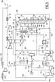
- a fifth installation 210 according to the invention is represented on the Figure 5 .
- This fifth installation 210 is intended for the implementation of a fifth method according to the invention.
- the fifth installation 210 is intended to advantageously increase the recovery of C 2 + in an existing installation including the type described in the patents US 4,157,904 and US 4,278,457 .
- the existing plant comprises the first heat exchanger 20, the first separator tank 22, the distillation column 30, the first compressor 32 coupled to the first expansion turbine 26 and the second compressor 36.
- the fifth installation 210 further comprises a second dynamic expansion turbine 40, a third compressor 41, and a downstream flask 152 for collecting the effluent from the second dynamic expansion turbine 40.
- the plant 210 further comprises an upstream heat exchanger 212, a downstream heat exchanger 214, and an auxiliary distillation column 216 provided with a bottom auxiliary pump 218.
- the fifth installation 210 also comprises a fourth compressor 220 interposed between two refrigerant 222A, 222B.
- the fifth installation 210 further comprises a downstream flask 152, disposed downstream of the second turbine 40.
- the fifth method according to the invention differs from the first method according to the invention in that the feed stream 16 is further separated into a third fraction 224 of the feed stream which is introduced into the upstream heat exchanger 212, before to be mixed with the first fraction 41A from the exchanger 20 to form the first fraction 42 cooled.
- the ratio of the molar flow rate of the third fraction 224 to the molar flow rate of the feed stream 16 is greater than 5%.
- the fifth method according to the invention differs from the first method according to the invention in that the second cooled and partially liquefied feed fraction 91A is introduced into the downstream flask 152.
- This fraction 91A is separated in the downstream flask 152 into a second liquid foot stream 154 and into a second gaseous head stream 156.
- the second liquid foot stream 154 is introduced into a fourth static expansion valve 157 to be substantially expanded under the pressure of the column 30 and form a second relaxed foot stream 158.
- the second head stream 156 coming from the downstream flask 152 is introduced into the downstream heat exchanger 214 to be cooled to a temperature below -70.degree. second cooled head stream 225.
- the second cooled overhead stream 225 is introduced into the auxiliary column 216 at a lower stage E1.
- Column 216 has a theoretical number of stages less than the number of theoretical stages of column 30. This number of stages is advantageously understood. between 1 and 7.
- the auxiliary column 216 operates at a pressure substantially equal to that of the column 30.
- the relaxed foot stream 158 obtained after expansion of the second foot stream 154 in the valve 157 is introduced into the column 30 at a level N1 advantageously corresponding to the first stage from the top of the column 30.
- a first portion 226 of the fraction 52 expanded in the valve 50 is introduced into the auxiliary column 216 at a stage E3 located above the level E1.
- a second portion 228 of the fraction 52 is introduced directly into the column 30 at the level N1, after mixing with the stream 158.
- Auxiliary column 216 produces a methane-rich head auxiliary stream 230 and a foot auxiliary current 232.
- the auxiliary head stream 230 is mixed with the methane-rich head stream 84 produced by the distillation column 30.
- Foot stream 232 is pumped by auxiliary pump 218 to form a cooled reflux stream 234 which is introduced into column 30 after mixing with stream 158.
- the stream 234 thus constitutes a cooled reflux stream which is obtained from a portion of the expanded fraction 91A resulting from the second dynamic expansion turbine 40, after separation of this effluent.
- the mixture 235 of the overhead streams 84 and 230 is separated into a first major fraction 236 of the overhead stream and a second minor fraction 238 of the overhead stream.
- the ratio of the molar flow rate of the majority fraction 236 to the minor fraction 238 is greater than 1.5.
- the majority fraction 236 is introduced successively into the second heat exchanger 28, then into the first heat exchanger 20, in order to form the heated overhead stream 86.
- the second overhead stream fraction 238 is passed through the downstream heat exchanger 214 countercurrently to the second overhead stream 156 to warm to a temperature above -50 ° C and form a second heated fraction 240. .
- the second heated fraction 240 is then separated into a return stream 242, and a compression stream 244.
- the return current 242 is reintroduced into the first head stream fraction 236, downstream of the second heat exchanger 28 and upstream of the first heat exchanger 20 to partially form the heated head stream 86.
- the recompression stream 244 is then introduced into the upstream exchanger 212 to cool the third fraction of the feed stream 224.
- the stream 244 warms to a temperature above -10 ° C to form a warmed recompression stream 246 .
- a first portion 248 of the recompression stream 246 is mixed with the first fraction of the overhead stream 86, downstream of the first heat exchanger 20 to form the heated overhead stream 87A.
- a second portion 250 of the recompression stream 246 is introduced into the third compressor 41, then into the refrigerant 222A, before being recompressed in the fourth compressor 220 and introduced into the refrigerant 222B.
- the second compressed portion 252 from the refrigerant 222B has a temperature below 60 ° C and in particular substantially equal to 40 ° C and a pressure greater than 35 bar and in particular equal to 63.1 bar.
- This first compressed portion 252 is mixed with the compressed overhead stream 90 to form the methane-rich stream 12.
- the fifth installation 210 and the fifth method according to the invention therefore make it possible to increase the C 2 + hydrocarbon recovery rate in an existing state of the art installation, without having to modify the existing equipment of the plant. installation, and in particular by keeping the heat exchangers 20 and 28, the column 30, the compressors 32, 36 and the turbine 26 identical and using the entries already present on the column 30.
- a sixth installation 270 according to the invention is represented on the Figure 6 .
- This sixth installation 270 is intended for the implementation of a sixth method according to the invention.
- the sixth method according to the invention differs from the fifth process according to the invention in that a withdrawal stream 92 is taken from the compressed methane-rich top stream 90, advantageously upstream of the point of introduction of the second compressed part. 252 in the current 90.
- the withdrawal stream 92 is reintroduced into the column 30 at a head level N14.
- the second portion 228 of the fraction 52 and the relaxed foot stream 158 are introduced into the column at a level N1 located below the N14 head level and above the N2 level.
- the pressure of the column 30 is slightly decreased.
- the presence of the new compressor 220 makes it possible to keep the power of the second compressor 36 the same despite the increase in the flow rate of the feed stream 16.
- the capacity of the first dynamic expansion turbine 26 has been kept constant.
- the second dynamic expansion turbine 40 is used to process the addition of capacity.
- auxiliary column 216 also prevents clogging of the column 30 during the flow increase.
- the sixth installation according to the invention makes it possible to maintain an ethane recovery greater than or equal to 99%, a temperature and a pressure of the feed stream 16 that are substantially identical. Similarly, the losses of charges allocated in the equipment, the efficiency of the trays in the column 30 and the position of the withdrawals, the maximum methane specification of the bottom stream 82 of the column 30, the efficiencies of the turbines and the compressors, the power of the second compressor 36 and the existing turbine 26 and the heat exchange coefficients of the existing exchangers 20 and 28 are kept identical.
- the second fraction 41B of the feed stream is taken from the first exchanger 20 and not upstream of it.
- the second fraction 41B is thus partially cooled and is partially liquefied in the first heat exchanger 20.
- the second fraction 41B issuing from the first heat exchanger 20 is then optionally introduced into an upstream separator tank 250. It is then separated in the upstream separator tank 250 in a second bottom liquid fraction 252 and in a second top gas fraction 254.
- the second bottom fraction 252 is expanded in a static expansion valve 256 to a pressure of less than 40 bar and substantially equal to the pressure of the column 30.
- the second fraction of relaxed foot 258 is then introduced into the column 30, advantageously between the level N11 and the level N8.
- the second head fraction 254 is introduced into the second dynamic expansion turbine 40 to form the second relaxed feed fraction 91A.
- This arrangement with an upstream separator tank is also applicable in the case where the feed stream 16 contains a liquid fraction.
- the installation comprises a bypass valve of a portion of the withdrawal stream 92 to divert this portion upstream of the first dynamic expansion turbine 26.
- a supplementary cooling stream is taken from the withdrawal stream obtained after passing through the first heat exchanger 20.
- the additional cooling stream is reintroduced upstream of the turbine 26, ie in the head stream 44, upstream of the balloon 22 in the cooled supply stream 42.
- the installation comprises a plurality of second exchangers 28, each being intended to receive a fraction of the overhead stream 84 and another stream.
- the overhead stream 84 is then divided into a plurality of fractions corresponding to the number of second exchangers 28.
- Each second heat exchanger 28 can then put in heat exchange only two flows each including a fraction of the overhead stream 84 and respectively, the first relaxed feed fraction 54, the second relaxed feed fraction 91A, and if necessary, the fraction column supply 46 and / or the sampling stream 92.
- a reboil stream is withdrawn from the distillation column at a sampling level.
- the reboiling current is then put in heat exchange relation with at least a part of the second expanded fraction 91A resulting from the dynamic expansion turbine 40 and optionally with the first expanded fraction 54 coming from the first turbine 26.
- This heat exchange connection can be performed within the second heat exchanger 28.
- an auxiliary expansion current is taken from the methane rich column head stream 86 from the first heat exchanger 20.
- This auxiliary expansion stream is introduced into a dynamic auxiliary expansion turbine, distinct from the first dynamic expansion turbine 26 and the second dynamic expansion turbine 40.
- the relaxed current from the auxiliary turbine is reintroduced into the methane-rich column head stream, before it passes through the first heat exchanger 20 to constitute a supplementary cooling stream of the first heat exchanger 20.
- the entire head stream 44 from the first flask 22 can form the turbine feed fraction 48.
- the method according to the invention is then devoid of separation of the overhead stream 44.
Landscapes
- Engineering & Computer Science (AREA)
- Physics & Mathematics (AREA)
- Mechanical Engineering (AREA)
- Thermal Sciences (AREA)
- General Engineering & Computer Science (AREA)
- Chemical & Material Sciences (AREA)
- Chemical Kinetics & Catalysis (AREA)
- General Chemical & Material Sciences (AREA)
- Oil, Petroleum & Natural Gas (AREA)
- Separation By Low-Temperature Treatments (AREA)
- Organic Low-Molecular-Weight Compounds And Preparation Thereof (AREA)
Claims (15)
- Verfahren zum Herstellen eines an Methan reichen Stroms (12) und eines an C2 +-Kohlenwasserstoffen reichen Stroms (14) ausgehend von einem Versorgungsstrom (16), der Kohlenwasserstoffe enthält, wobei das Verfahren die folgenden Schritte umfasst:- Trennen des Versorgungsstroms (16) in eine erste Fraktion (41A) des Versorgungsstroms und in wenigstens eine zweite Fraktion (41B) des Versorgungsstroms;- Kühlen der ersten Fraktion (41A) des Versorgungsstroms in einem ersten Wärmetauscher (20);- Einleiten der ersten Fraktion des gekühlten Versorgungsstroms (42) in einen ersten Ballonabscheider (22), um einen leichten Kopfstrom (44) und einen schweren Fußstrom (45) zu erzeugen;- Entspannen einer Turbinenversorgungsfraktion (48), die anhand des leichten Kopfstroms (44) gebildet wird, in einer ersten Turbine (26) mit dynamischer Entspannung bis zu einem ersten Druck (P1) und Einleiten wenigstens eines Teils (56) der ersten entspannten Fraktion (54), die von der ersten Turbine (26) stammt, in eine erste Destillationskolonne (30);- Entspannen wenigstens eines Teils des schweren Fußstroms (45), um einen entspannten Fußstrom (60) zu bilden, und Einleiten des entspannten Fußstroms (60) in die erste Destillationskolonne (30) ohne Durchgang durch den ersten Wärmetauscher (20) zwischen dem ersten Ballonabscheider (22) und der ersten Destillationskolonne (30);- Wiedergewinnen eines Kolonnenbodenstroms (82) am Fuß der ersten Destillationskolonne (30), wobei der an C2 +-Kohlenwasserstoffen reiche Strom (14) anhand des Kolonnenbodenstroms (82) gebildet wird;- Wiedergewinnen und erneutes Erwärmen des an Methan reichen Kolonnenkopfstroms (84),- Komprimieren wenigstens einer Fraktion des Kolonnenkopfstroms (84) in wenigstens einem ersten Verdichter (32), der mit der ersten Turbine (26) mit dynamischer Entspannung gekoppelt ist, und in wenigstens einem zweiten Verdichter (36);- Bilden eines an Methan reichen Stroms (12) anhand des wiedererwärmten und verdichteten Kolonnenkopfstroms (90);wobei das Verfahren die folgenden Schritte umfasst:- Entspannen wenigstens eines Teils der zweiten Fraktion (41B) des Versorgungsstroms in einer zweiten Turbine (40) mit dynamischer Entspannung, die von der ersten Turbine (26) mit dynamischer Entspannung verschieden ist, bis auf einen zweiten Druck, um eine zweite entspannte Fraktion (91A) zu bilden, die von der zweiten Turbine (40) mit dynamischer Entspannung stammt,- Kühlen und wenigstens teilweise Verflüssigen wenigstens eines Teils der zweiten entspannten Fraktion (91A), die von der zweiten Turbine (40) mit dynamischer Entspannung stammt, um einen gekühlten Rückflussstrom (91B; 160; 232) zu bilden, und Einleiten des gekühlten Rückflussstroms (91B; 160; 232) in die erste Destillationskolonne (30),dadurch gekennzeichnet, dass der zweite Druck (P2) im Wesentlichen gleich dem ersten Druck (P1) ist, damit die Differenz zwischen dem ersten Druck und dem zweiten Druck kleiner als 8 Bar ist,
und dass die Gesamtheit der zweiten Fraktion (41B) des Versorgungsstroms in die zweite Turbine (40) mit dynamischer Entspannung ohne Kühlung zwischen dem Schritt des Trennens des Versorgungsstroms (16) und dem Schritt des Einleitens der zweiten Fraktion (41B) des Versorgungsstroms in die zweite Turbine (40) mit dynamischer Entspannung eingeleitet wird. - Verfahren nach Anspruch 1, dadurch gekennzeichnet, dass es das Einleiten der ersten entspannten Fraktion (54), die von der ersten Turbine (26) mit dynamischer Entspannung stammt, in einen zweiten Wärmetauscher (28), um darin gekühlt und teilweise verflüssigt zu werden, umfasst, wobei die erste gekühlte entspannte Fraktion einen zusätzlichen gekühlten Rückflussstrom (56) bildet, wobei das Verfahren das Einleiten des zusätzlichen gekühlten Rückflussstroms (56) in die erste Destillationskolonne (30) umfasst.
- Verfahren nach einem der vorhergehenden Ansprüche, dadurch gekennzeichnet, dass es die folgenden Schritte umfasst:- Einleiten der zweiten entspannten Fraktion (91A), die von der zweiten Turbine (40) mit dynamischer Entspannung stammt, in einen stromabseitigen Ballonabscheider (152), um einen zweiten gasförmigen Kopfstrom (156) und einen zweiten flüssigen Fußstrom (154) zu bilden,- Kühlen des zweiten gasförmigen Kopfstroms (156), um einen gekühlten Rückflussstrom zu bilden.
- Verfahren nach einem der vorhergehenden Ansprüche, dadurch gekennzeichnet, dass es die folgenden Schritte umfasst:- Einleiten wenigstens eines Teils der zweiten entspannten Fraktion (91A), die von der zweiten Turbine (40) mit dynamischer Entspannung stammt, in eine Hilfskolonne (216) und- Bilden des gekühlten Rückflussstroms anhand des Fußstroms (232) der Hilfskolonne (216).
- Verfahren nach einem der vorhergehenden Ansprüche, dadurch gekennzeichnet, dass es die folgenden Schritte umfasst:- Abgreifen einer sekundären Verdichtungsfraktion (87B) in dem an Methan reichen Kolonnenkopfstrom (86) vor dem Durchgang einer Fraktion (87A) des an Methan reichen Kopfstroms durch den ersten Verdichter (32),- Schicken der sekundären Fraktion (87B) in einen dritten Verdichter (41, der mit der zweiten Turbine (40) mit dynamischer Entspannung gekoppelt ist;- Einleiten der verdichteten sekundären Fraktion, die von dem dritten Verdichter (41) stammt, in die Fraktion des verdichteten Kolonnenkopfstroms stromabseitig des ersten Verdichters (32).
- Verfahren nach einem der vorhergehenden Ansprüche, dadurch gekennzeichnet, dass der zweite Verdichter (36) eine erste Verdichtungsstufe, wenigstens eine zweite Verdichtungsstufe und einen Kühler, der zwischen die erste Verdichtungsstufe und die zweite Verdichtungsstufe eingefügt ist, umfasst, wobei das Verfahren einen Schritt des Schickens des verdichteten Kolonnenkopfstroms (88), der von dem ersten Verdichter stammt, nacheinander in die erste Verdichtungsstufe, in den Kühler und dann in die zweite Verdichtungsstufe umfasst.
- Verfahren nach einem der vorhergehenden Ansprüche, dadurch gekennzeichnet, dass wenigstens ein Teil der zweiten entspannten Fraktion (91A), die von der zweiten Turbine (40) mit dynamischer Entspannung stammt, wenigstens eine Fraktion des Kolonnenkopfstroms (84) und eventuell die erste entspannte Fraktion (54), die von der ersten Turbine (26) mit dynamischer Entspannung stammt, in einer Wärmeaustauschbeziehung angeordnet werden.
- Verfahren nach einem der vorhergehenden Ansprüche, dadurch gekennzeichnet, dass es die folgenden Schritte umfasst:- Unterteilen des leichten Kopfstroms (44) in die Turbinenversorgungsfraktion (48) und in eine Kolonnenversorgungsfraktion (46);- Kühlen und wenigstens teilweise Kondensieren der Kolonnenversorgungsfraktion (46) in einem zweiten Wärmetauscher (28),- Entspannen und wenigstens teilweise Einleiten der gekühlten Kolonnenversorgungsfraktion in die erste Destillationskolonne (30),wobei wenigstens ein Teil der zweiten entspannten Fraktion (91A), die von der zweiten Turbine (40) mit dynamischer Entspannung stammt, und die Kolonnenversorgungsfraktion (46) vorteilhaft in einer Wärmeaustauschbeziehung angeordnet werden.
- Verfahren nach Anspruch 8, dadurch gekennzeichnet, dass wenigstens eine Fraktion (238) des Kolonnenkopfstroms (84) und wenigstens ein Teil der zweiten entspannten Fraktion (91A), die von der zweiten Turbine mit dynamischer Entspannung stammt, in einer Wärmeaustauschbeziehung in einem stromabseitigen Wärmetauscher (214), der von dem zweiten Wärmetauscher (28) verschieden ist, angeordnet werden.
- Verfahren nach einem der vorhergehenden Ansprüche, dadurch gekennzeichnet, dass es die folgenden Schritte umfasst:- Abgreifen eines Anzapfstroms (92) in dem Kolonnenkopfstrom (90);- Kühlen des Anzapfstroms wenigstens in dem ersten Wärmetauscher (20) und Einleiten des gekühlten Anzapfstroms (96) in die erste Destillationskolonne (30);- eventuell Ausführen eines Wärmeaustauschs zwischen dem Anzapfstrom und wenigstens einem Teil der zweiten entspannten Fraktion (91A), die von der zweiten Turbine (40) stammt.
- Verfahren nach einem der vorhergehenden Ansprüche, dadurch gekennzeichnet, dass es die folgenden Schritte umfasst:- Abgreifen eines Aufkochstroms (80) in der ersten Destillationskolonne (30) auf einer Abgreifhöhe;- Herstellen einer Wärmeaustauschbeziehung zwischen dem Aufkochstrom (80) und wenigstens einem Teil der zweiten entspannten Fraktion (91A), die von der zweiten Turbine (40) mit dynamischer Entspannung stammt, um den Teil der zweiten entspannten Fraktion (91A), die von der zweiten Turbine mit dynamischer Entspannung stammt, zu kühlen und wenigstens teilweise zu verflüssigen; und- eventuell Herstellen einer Wärmeaustauschbeziehung mit der ersten entspannten Fraktion, die von der ersten Turbine (26) stammt;- erneutes Einleiten des Aufkochstroms (80) in die erste Destillationskolonne (30) auf einer Höhe, die niedriger als die Abgreifhöhe ist.
- Verfahren nach einem der vorhergehenden Ansprüche, dadurch gekennzeichnet, dass es die folgenden Schritte umfasst:- Abgreifen eines Unterstützungskühlungsstroms in dem an Methan reichen Kopfstrom (84, 86, 88, 90) oder in einem Strom (92), der anhand des an Methan reichen Kopfstroms (84, 86, 88, 90) gebildet wird;- Entspannen und Einleiten des entspannten Zusatzkühlungsstroms in einen Strom (42, 48), der stromaufseitig der ersten Entspannungsturbine (26) zirkuliert, vorteilhaft in die erste Fraktion des gekühlten Versorgungsstroms (42) oder in die Turbinenversorgungsfraktion (48).
- Verfahren nach einem der vorhergehenden Ansprüche, dadurch gekennzeichnet, dass es die folgenden Schritte umfasst:- Schicken des an Methan reichen Kopfstroms (84) in den ersten Wärmetauscher (20);- Abgreifen eines Hilfsentspannungsstroms in dem an Methan reichen Kopfstrom (84) nach seinem Durchgang durch den ersten Wärmetauscher (20);- dynamisches Entspannen des Hilfsentspannungsstroms in einer Hilfsturbine mit dynamischer Entspannung;- Einleiten des entspannten Stroms, der von der Hilfsturbine mit dynamischer Entspannung stammt, in den an Methan reichen Kolonnenkopfstrom vor seinem Durchgang durch den ersten Wärmetauscher (20).
- Anlage für die Herstellung eines an Methan reichen Stroms (12) und eines an C2 +-Kohlenwasserstoffen reichen Stroms (14) anhand eines Versorgungsstroms (16), der Kohlenwasserstoffe enthält, des Typs, der Folgendes umfasst:- Mittel zum Trennen des Versorgungsstroms (16) in eine erste Fraktion (41A) des Versorgungsstroms und in wenigstens eine zweite Fraktion (41B) des Versorgungsstroms;- einen ersten Wärmetauscher (20) zum Kühlen der ersten Fraktion (41A) des Versorgungsstroms;- Mittel zum Einleiten der ersten gekühlten Versorgungsfraktion (42) in einen ersten Ballonabscheider (22), um einen leichten Kopfstrom (44) und einen schweren Fußstrom (45) zu erzeugen;- eine erste Turbine (26) mit dynamischer Entspannung und Mittel zum Einleiten einer Turbinenversorgungsfraktion (48), die anhand des leichten Kopfstroms gebildet wird, in die erste Turbine (26) mit dynamischer Entspannung, um die Turbinenversorgungsfraktion (48) bis auf einen ersten Druck zu entspannen;- eine erste Destillationskolonne (30);- Mittel zum Einleiten wenigstens eines Teils (56) der ersten entspannten Fraktion (54) in der ersten Turbine (26) in die erste Destillationskolonne (30);- Mittel zum Entspannen wenigstens eines Teils des schweren Fußstroms (45), um einen entspannten Fußstrom zu bilden, und Mittel zum Einleiten wenigstens eines Teils des entspannten Fußstroms (60) in die erste Destillationskolonne (30), wobei die Mittel zum Einleiten des entspannten Fußstroms so konfiguriert sind, dass der Fußstrom (45) nicht durch den ersten Wärmetauscher (20) zwischen dem ersten Ballonabscheider und der ersten Destillationskolonne (30) verläuft;- Mittel zum Wiedergewinnen eines Kolonnenbodenstroms (82) am Fuß der ersten Destillationskolonne (30), wobei der an C2 +-Kohlenwasserstoffen reiche Strom (14) anhand des Kolonnenbodenstroms (82) gebildet wird;- Mittel zum Wiedergewinnen und erneuten Erwärmen des an Methan reichen Kolonnenkopfstroms (84),- wenigstens einen ersten Verdichter (32), der mit der ersten Turbine (26) mit dynamischer Entspannung gekoppelt ist, und wenigstens einen zweiten Verdichter (36), um wenigstens eine Fraktion des Kolonnenkopfstroms (84) zu verdichten;- Mittel zum Bilden des an Methan reichen Stroms (12) anhand des erneut erwärmten und verdichteten Kolonnenkopfstroms (90), der von dem zweiten Verdichter (36) stammt;wobei die Anlage Folgendes umfasst:- eine zweite Turbine (40) mit dynamischer Entspannung, die von der ersten Turbine (26) mit dynamischer Entspannung verschieden ist,- Mittel zum Einleiten wenigstens eines Teils der zweiten Fraktion (41B) des Versorgungsstroms in die zweite Turbine (40) mit dynamischer Entspannung, um eine zweite entspannte Fraktion (91A) zu bilden, die von der zweiten Turbine (40) mit dynamischer Entspannung stammt und einen zweiten Druck besitzt,- Mittel zum Kühlen und wenigstens teilweisen Verflüssigen wenigstens eines Teils der zweiten Fraktion (91A), die von der zweiten Turbine (40) mit dynamischer Entspannung stammt, um einen gekühlten Rückflussstrom (91B; 160; 232) zu bilden, und Mittel zum Einleiten des gekühlten Rückflussstroms (91B; 160; 232) in die erste Destillationskolonne (30),dadurch gekennzeichnet, dass die zweite Turbine mit dynamischer Entspannung so beschaffen ist, dass der zweite Druck im Wesentlichen gleich dem ersten Druck ist, damit die Differenz zwischen dem ersten Druck und dem zweiten Druck kleiner als 8 Bar ist;
und dass die Anlage (10) so konfiguriert ist, dass die Gesamtheit der zweiten Fraktion (41B) des Versorgungsstroms in die zweite Turbine (40) mit dynamischer Entspannung ohne Kühlung zwischen dem Schritt des Trennens des Versorgungsstroms (16) und dem Schritt des Einleitens der zweiten Fraktion (41B) des Versorgungsstroms in die zweite Turbine (40) mit dynamischer Entspannung eingeleitet wird. - Anlage nach Anspruch 14, dadurch gekennzeichnet, dass sie Folgendes umfasst:- eine Hilfskolonne (216);- Mittel zum Einleiten wenigstens eines Teils der zweiten entspannten Fraktion (91A), die von der zweiten Turbine (40) mit dynamischer Entspannung stammt, in die Hilfskolonne (216); und- Mittel zum Bilden des gekühlten Rückflussstroms anhand des Fußstroms (232) der Hilfskolonne (216).
Applications Claiming Priority (2)
| Application Number | Priority Date | Filing Date | Title |
|---|---|---|---|
| FR1061273A FR2969745B1 (fr) | 2010-12-27 | 2010-12-27 | Procede de production d'un courant riche en methane et d'un courant riche en hydrocarbures en c2+ et installation associee. |
| PCT/EP2011/074051 WO2012089709A2 (fr) | 2010-12-27 | 2011-12-26 | Procédé de production d'un courant riche en methane et d'un courant riche en hydrocarbures en c2 + et installation associee |
Publications (2)
| Publication Number | Publication Date |
|---|---|
| EP2659211A2 EP2659211A2 (de) | 2013-11-06 |
| EP2659211B1 true EP2659211B1 (de) | 2019-05-08 |
Family
ID=44545322
Family Applications (1)
| Application Number | Title | Priority Date | Filing Date |
|---|---|---|---|
| EP11802438.9A Active EP2659211B1 (de) | 2010-12-27 | 2011-12-26 | Verfahren zur herstellung eines methanreichen stroms und eines c2+kohlenwasserstoffreichen stroms sowie zugehörige anlage |
Country Status (7)
| Country | Link |
|---|---|
| US (2) | US10619919B2 (de) |
| EP (1) | EP2659211B1 (de) |
| AR (1) | AR084608A1 (de) |
| CA (1) | CA2822766C (de) |
| FR (1) | FR2969745B1 (de) |
| MX (1) | MX362997B (de) |
| WO (1) | WO2012089709A2 (de) |
Families Citing this family (14)
| Publication number | Priority date | Publication date | Assignee | Title |
|---|---|---|---|---|
| FR2969745B1 (fr) | 2010-12-27 | 2013-01-25 | Technip France | Procede de production d'un courant riche en methane et d'un courant riche en hydrocarbures en c2+ et installation associee. |
| US20140075987A1 (en) | 2012-09-20 | 2014-03-20 | Fluor Technologies Corporation | Configurations and methods for ngl recovery for high nitrogen content feed gases |
| US20140260421A1 (en) * | 2013-03-14 | 2014-09-18 | Ipsi L.L.C | Systems and Methods for Enhanced Recovery of NGL Hydrocarbons |
| FR3012150B1 (fr) | 2013-10-23 | 2016-09-02 | Technip France | Procede de fractionnement d'un courant de gaz craque, mettant en oeuvre un courant de recycle intermediaire, et installation associee |
| CN104792116B (zh) * | 2014-11-25 | 2017-08-08 | 中国寰球工程公司 | 一种天然气回收乙烷及乙烷以上轻烃的系统及工艺 |
| EP3040405A1 (de) | 2014-12-30 | 2016-07-06 | Technip France | Verfahren zur Verbesserung der Proplyenrückgewinnung von fluidkatalytischer Krackereinheit |
| US10330382B2 (en) | 2016-05-18 | 2019-06-25 | Fluor Technologies Corporation | Systems and methods for LNG production with propane and ethane recovery |
| CA3033088C (en) | 2016-09-09 | 2025-05-13 | Fluor Technologies Corporation | PROCESSES AND CONFIGURATION FOR REASPRACTING AN LNG PLANT FOR ETHANUM RECOVERY |
| US11112175B2 (en) | 2017-10-20 | 2021-09-07 | Fluor Technologies Corporation | Phase implementation of natural gas liquid recovery plants |
| US11248839B2 (en) | 2017-12-15 | 2022-02-15 | Saudi Arabian Oil Company | Process integration for natural gas liquid recovery |
| US11555651B2 (en) * | 2018-08-22 | 2023-01-17 | Exxonmobil Upstream Research Company | Managing make-up gas composition variation for a high pressure expander process |
| US12215922B2 (en) | 2019-05-23 | 2025-02-04 | Fluor Technologies Corporation | Integrated heavy hydrocarbon and BTEX removal in LNG liquefaction for lean gases |
| US12098882B2 (en) * | 2018-12-13 | 2024-09-24 | Fluor Technologies Corporation | Heavy hydrocarbon and BTEX removal from pipeline gas to LNG liquefaction |
| FR3116109B1 (fr) * | 2020-11-10 | 2022-11-18 | Technip France | Procédé d’extraction d’éthane dans un courant de gaz naturel de départ et installation correspondante |
Family Cites Families (26)
| Publication number | Priority date | Publication date | Assignee | Title |
|---|---|---|---|---|
| CA1021254A (en) * | 1974-10-22 | 1977-11-22 | Ortloff Corporation (The) | Natural gas processing |
| US4155729A (en) * | 1977-10-20 | 1979-05-22 | Phillips Petroleum Company | Liquid flash between expanders in gas separation |
| US5983664A (en) * | 1997-04-09 | 1999-11-16 | Elcor Corporation | Hydrocarbon gas processing |
| US5881569A (en) * | 1997-05-07 | 1999-03-16 | Elcor Corporation | Hydrocarbon gas processing |
| US6271433B1 (en) | 1999-02-22 | 2001-08-07 | Stone & Webster Engineering Corp. | Cat cracker gas plant process for increased olefins recovery |
| US6303841B1 (en) | 1999-10-04 | 2001-10-16 | Uop Llc | Process for producing ethylene |
| FR2817767B1 (fr) | 2000-12-07 | 2003-02-28 | Technip Cie | Procede et installation pour la recuperation et la purification de l'ethylene produit par pyrolyse d'hydrocarbures, et gaz obtenus par procede |
| FR2817766B1 (fr) * | 2000-12-13 | 2003-08-15 | Technip Cie | Procede et installation de separation d'un melange gazeux contenant du methane par distillation,et gaz obtenus par cette separation |
| US6526777B1 (en) * | 2001-04-20 | 2003-03-04 | Elcor Corporation | LNG production in cryogenic natural gas processing plants |
| US6889523B2 (en) * | 2003-03-07 | 2005-05-10 | Elkcorp | LNG production in cryogenic natural gas processing plants |
| US7294749B2 (en) | 2004-07-02 | 2007-11-13 | Kellogg Brown & Root Llc | Low pressure olefin recovery process |
| MX2008000718A (es) * | 2005-07-25 | 2008-03-19 | Fluor Tech Corp | Procedimientos y configuraciones para la recuperacion de ngl. |
| DE102006005822A1 (de) | 2006-02-08 | 2007-08-23 | Linde Ag | Verfahren zur Kälteversorgung der Tieftemperaturtrennungsstufe einer Olefinanlage |
| AU2007267116B2 (en) * | 2006-05-30 | 2010-08-12 | Shell Internationale Research Maatschappij B.V. | Method for treating a hydrocarbon stream |
| US20080081938A1 (en) | 2006-09-28 | 2008-04-03 | Schultz Michael A | Absorption recovery processing of light olefins free of carbon dioxide |
| EP2028439A1 (de) * | 2007-07-26 | 2009-02-25 | Renishaw plc | Abschaltbares Messgerät |
| US7605603B1 (en) * | 2008-02-29 | 2009-10-20 | Altera Corporation | User-accessible freeze-logic for dynamic power reduction and associated methods |
| US20090282865A1 (en) * | 2008-05-16 | 2009-11-19 | Ortloff Engineers, Ltd. | Liquefied Natural Gas and Hydrocarbon Gas Processing |
| FR2944523B1 (fr) * | 2009-04-21 | 2011-08-26 | Technip France | Procede de production d'un courant riche en methane et d'une coupe riche en hydrocarbures en c2+ a partir d'un courant de gaz naturel de charge, et installation associee |
| US8683824B2 (en) * | 2009-04-24 | 2014-04-01 | Ebara International Corporation | Liquefied gas expander and integrated Joule-Thomson valve |
| EP2449059B1 (de) | 2009-07-02 | 2020-05-27 | Reliance Industries Limited | Verbessertes verfahren zur wiederherstellung von propylen und lpg aus einem fcc-brennstoffgas unter verwendung eines abgestreiften hauptsäulen-overheaddestillats als absorberöl |
| FR2947897B1 (fr) * | 2009-07-09 | 2014-05-09 | Technip France | Procede de production d'un courant riche en methane et d'un courant riche en hydrocarbures en c2+, et installation associee. |
| FR2951815B1 (fr) | 2009-10-27 | 2012-09-07 | Technip France | Procede de fractionnement d'un courant de gaz craque pour obtenir une coupe riche en ethylene et un courant de combustible, et installation associee. |
| KR101379539B1 (ko) | 2009-11-09 | 2014-03-28 | 유오피 엘엘씨 | Fcc 생성물을 회수하는 장치 및 방법 |
| WO2012015546A1 (en) * | 2010-07-30 | 2012-02-02 | Exxonmobil Upstream Research Company | Systems and methods for using multiple cryogenic hydraulic turbines |
| FR2969745B1 (fr) | 2010-12-27 | 2013-01-25 | Technip France | Procede de production d'un courant riche en methane et d'un courant riche en hydrocarbures en c2+ et installation associee. |
-
2010
- 2010-12-27 FR FR1061273A patent/FR2969745B1/fr not_active Expired - Fee Related
-
2011
- 2011-12-26 MX MX2013007552A patent/MX362997B/es unknown
- 2011-12-26 WO PCT/EP2011/074051 patent/WO2012089709A2/fr not_active Ceased
- 2011-12-26 US US13/976,307 patent/US10619919B2/en active Active
- 2011-12-26 CA CA2822766A patent/CA2822766C/fr active Active
- 2011-12-26 EP EP11802438.9A patent/EP2659211B1/de active Active
- 2011-12-27 AR ARP110104951A patent/AR084608A1/es active IP Right Grant
-
2020
- 2020-03-06 US US16/811,953 patent/US20200208911A1/en not_active Abandoned
Non-Patent Citations (1)
| Title |
|---|
| None * |
Also Published As
| Publication number | Publication date |
|---|---|
| MX2013007552A (es) | 2013-08-21 |
| US20140290307A1 (en) | 2014-10-02 |
| EP2659211A2 (de) | 2013-11-06 |
| US20200208911A1 (en) | 2020-07-02 |
| MX362997B (es) | 2019-03-01 |
| US10619919B2 (en) | 2020-04-14 |
| AR084608A1 (es) | 2013-05-29 |
| CA2822766A1 (fr) | 2012-07-05 |
| FR2969745A1 (fr) | 2012-06-29 |
| WO2012089709A3 (fr) | 2012-12-20 |
| WO2012089709A2 (fr) | 2012-07-05 |
| FR2969745B1 (fr) | 2013-01-25 |
| CA2822766C (fr) | 2019-04-09 |
Similar Documents
| Publication | Publication Date | Title |
|---|---|---|
| EP2659211B1 (de) | Verfahren zur herstellung eines methanreichen stroms und eines c2+kohlenwasserstoffreichen stroms sowie zugehörige anlage | |
| EP2452140B1 (de) | Verfahren zur herstellung eines methanreichen stroms und c2+kohlenwasserstoffreichen stroms und zugehörige anlage | |
| EP2344821B1 (de) | Verfahren zur erzeugung von flüssigen und gasförmigen stickstoffströmen, heliumreicher, gasförmiger strom und stickstoffabgereicherter kohlenwasserstoffstrom und zugehörige anlage | |
| EP1454104B1 (de) | Verfahren und vorrichutng zur zerlegung eines methan enthaltenden gasgemisches durch rektifikation | |
| EP2422152B1 (de) | Verfahren zur herstellung eines methanreichen stroms und einer c2+-kohlenwasserstoffreichen fraktion aus einem erdgaseinsatzstrom und entsprechende einrichtung | |
| EP0572590B1 (de) | Stickstoffentfernungsverfahren aus einem hauptsächlich methan enthaltenden kohlenwasserstoffeinsatzgemisch mit mindestens 2 mol % stickstoff | |
| EP3168558B1 (de) | System und verfahren zur verflüssigung von erdgas | |
| AU705205B2 (en) | Removing carbon dioxide, ethane and heavier components from a natural gas | |
| AU2015315557B2 (en) | Production of low pressure liquid carbon dioxide from a power production system and method | |
| US20140069142A1 (en) | Two Step Nitrogen and Methane Separation Process | |
| WO2012052681A2 (fr) | Procédé simplifié de production d'un courant riche en méthane et d'une coupe riche en hydrocarbures en c2+ à partir d'un courant de gaz naturel de charge, et installation associée. | |
| CA2823900C (fr) | Procede de production d'une coupe riche en hydrocarbures c3+ et d'un courant riche en methane et ethane | |
| EP4244557B1 (de) | Verfahren zur extraktion von ethan aus einem anfänglichen erdgasstrom und entsprechende anlage | |
| EP3060629B1 (de) | Verfahren zur fraktionierung eines stromes von spaltgas unter verwendung eines zwischensrückführungsstromes und zugehörige anlage | |
| AU2009277374B2 (en) | Method and apparatus for treating a hydrocarbon stream and method of cooling a hydrocarbon stream | |
| FR2928720A1 (fr) | Procede de pretraitement d'un gaz naturel pour retirer le dioxyde de carbone |
Legal Events
| Date | Code | Title | Description |
|---|---|---|---|
| PUAI | Public reference made under article 153(3) epc to a published international application that has entered the european phase |
Free format text: ORIGINAL CODE: 0009012 |
|
| 17P | Request for examination filed |
Effective date: 20130611 |
|
| AK | Designated contracting states |
Kind code of ref document: A2 Designated state(s): AL AT BE BG CH CY CZ DE DK EE ES FI FR GB GR HR HU IE IS IT LI LT LU LV MC MK MT NL NO PL PT RO RS SE SI SK SM TR |
|
| RIN1 | Information on inventor provided before grant (corrected) |
Inventor name: THIEBAULT, SANDRA Inventor name: GOURIOU, JULIE Inventor name: BARTHE, LOIC Inventor name: GAHIER, VANESSA |
|
| DAX | Request for extension of the european patent (deleted) | ||
| GRAP | Despatch of communication of intention to grant a patent |
Free format text: ORIGINAL CODE: EPIDOSNIGR1 |
|
| STAA | Information on the status of an ep patent application or granted ep patent |
Free format text: STATUS: GRANT OF PATENT IS INTENDED |
|
| INTG | Intention to grant announced |
Effective date: 20181127 |
|
| GRAS | Grant fee paid |
Free format text: ORIGINAL CODE: EPIDOSNIGR3 |
|
| GRAA | (expected) grant |
Free format text: ORIGINAL CODE: 0009210 |
|
| STAA | Information on the status of an ep patent application or granted ep patent |
Free format text: STATUS: THE PATENT HAS BEEN GRANTED |
|
| AK | Designated contracting states |
Kind code of ref document: B1 Designated state(s): AL AT BE BG CH CY CZ DE DK EE ES FI FR GB GR HR HU IE IS IT LI LT LU LV MC MK MT NL NO PL PT RO RS SE SI SK SM TR |
|
| REG | Reference to a national code |
Ref country code: GB Ref legal event code: FG4D Free format text: NOT ENGLISH |
|
| REG | Reference to a national code |
Ref country code: CH Ref legal event code: EP Ref country code: AT Ref legal event code: REF Ref document number: 1130805 Country of ref document: AT Kind code of ref document: T Effective date: 20190515 |
|
| REG | Reference to a national code |
Ref country code: DE Ref legal event code: R096 Ref document number: 602011058826 Country of ref document: DE Ref country code: IE Ref legal event code: FG4D Free format text: LANGUAGE OF EP DOCUMENT: FRENCH |
|
| REG | Reference to a national code |
Ref country code: RO Ref legal event code: EPE |
|
| REG | Reference to a national code |
Ref country code: NL Ref legal event code: MP Effective date: 20190508 |
|
| REG | Reference to a national code |
Ref country code: LT Ref legal event code: MG4D |
|
| REG | Reference to a national code |
Ref country code: NO Ref legal event code: T2 Effective date: 20190508 |
|
| PG25 | Lapsed in a contracting state [announced via postgrant information from national office to epo] |
Ref country code: NL Free format text: LAPSE BECAUSE OF FAILURE TO SUBMIT A TRANSLATION OF THE DESCRIPTION OR TO PAY THE FEE WITHIN THE PRESCRIBED TIME-LIMIT Effective date: 20190508 Ref country code: AL Free format text: LAPSE BECAUSE OF FAILURE TO SUBMIT A TRANSLATION OF THE DESCRIPTION OR TO PAY THE FEE WITHIN THE PRESCRIBED TIME-LIMIT Effective date: 20190508 Ref country code: PT Free format text: LAPSE BECAUSE OF FAILURE TO SUBMIT A TRANSLATION OF THE DESCRIPTION OR TO PAY THE FEE WITHIN THE PRESCRIBED TIME-LIMIT Effective date: 20190908 Ref country code: SE Free format text: LAPSE BECAUSE OF FAILURE TO SUBMIT A TRANSLATION OF THE DESCRIPTION OR TO PAY THE FEE WITHIN THE PRESCRIBED TIME-LIMIT Effective date: 20190508 Ref country code: LT Free format text: LAPSE BECAUSE OF FAILURE TO SUBMIT A TRANSLATION OF THE DESCRIPTION OR TO PAY THE FEE WITHIN THE PRESCRIBED TIME-LIMIT Effective date: 20190508 Ref country code: HR Free format text: LAPSE BECAUSE OF FAILURE TO SUBMIT A TRANSLATION OF THE DESCRIPTION OR TO PAY THE FEE WITHIN THE PRESCRIBED TIME-LIMIT Effective date: 20190508 Ref country code: ES Free format text: LAPSE BECAUSE OF FAILURE TO SUBMIT A TRANSLATION OF THE DESCRIPTION OR TO PAY THE FEE WITHIN THE PRESCRIBED TIME-LIMIT Effective date: 20190508 Ref country code: FI Free format text: LAPSE BECAUSE OF FAILURE TO SUBMIT A TRANSLATION OF THE DESCRIPTION OR TO PAY THE FEE WITHIN THE PRESCRIBED TIME-LIMIT Effective date: 20190508 |
|
| PG25 | Lapsed in a contracting state [announced via postgrant information from national office to epo] |
Ref country code: RS Free format text: LAPSE BECAUSE OF FAILURE TO SUBMIT A TRANSLATION OF THE DESCRIPTION OR TO PAY THE FEE WITHIN THE PRESCRIBED TIME-LIMIT Effective date: 20190508 Ref country code: BG Free format text: LAPSE BECAUSE OF FAILURE TO SUBMIT A TRANSLATION OF THE DESCRIPTION OR TO PAY THE FEE WITHIN THE PRESCRIBED TIME-LIMIT Effective date: 20190808 Ref country code: GR Free format text: LAPSE BECAUSE OF FAILURE TO SUBMIT A TRANSLATION OF THE DESCRIPTION OR TO PAY THE FEE WITHIN THE PRESCRIBED TIME-LIMIT Effective date: 20190809 Ref country code: LV Free format text: LAPSE BECAUSE OF FAILURE TO SUBMIT A TRANSLATION OF THE DESCRIPTION OR TO PAY THE FEE WITHIN THE PRESCRIBED TIME-LIMIT Effective date: 20190508 |
|
| REG | Reference to a national code |
Ref country code: AT Ref legal event code: MK05 Ref document number: 1130805 Country of ref document: AT Kind code of ref document: T Effective date: 20190508 |
|
| PG25 | Lapsed in a contracting state [announced via postgrant information from national office to epo] |
Ref country code: AT Free format text: LAPSE BECAUSE OF FAILURE TO SUBMIT A TRANSLATION OF THE DESCRIPTION OR TO PAY THE FEE WITHIN THE PRESCRIBED TIME-LIMIT Effective date: 20190508 Ref country code: DK Free format text: LAPSE BECAUSE OF FAILURE TO SUBMIT A TRANSLATION OF THE DESCRIPTION OR TO PAY THE FEE WITHIN THE PRESCRIBED TIME-LIMIT Effective date: 20190508 Ref country code: CZ Free format text: LAPSE BECAUSE OF FAILURE TO SUBMIT A TRANSLATION OF THE DESCRIPTION OR TO PAY THE FEE WITHIN THE PRESCRIBED TIME-LIMIT Effective date: 20190508 Ref country code: SK Free format text: LAPSE BECAUSE OF FAILURE TO SUBMIT A TRANSLATION OF THE DESCRIPTION OR TO PAY THE FEE WITHIN THE PRESCRIBED TIME-LIMIT Effective date: 20190508 Ref country code: EE Free format text: LAPSE BECAUSE OF FAILURE TO SUBMIT A TRANSLATION OF THE DESCRIPTION OR TO PAY THE FEE WITHIN THE PRESCRIBED TIME-LIMIT Effective date: 20190508 |
|
| REG | Reference to a national code |
Ref country code: DE Ref legal event code: R097 Ref document number: 602011058826 Country of ref document: DE |
|
| PG25 | Lapsed in a contracting state [announced via postgrant information from national office to epo] |
Ref country code: IT Free format text: LAPSE BECAUSE OF FAILURE TO SUBMIT A TRANSLATION OF THE DESCRIPTION OR TO PAY THE FEE WITHIN THE PRESCRIBED TIME-LIMIT Effective date: 20190508 Ref country code: SM Free format text: LAPSE BECAUSE OF FAILURE TO SUBMIT A TRANSLATION OF THE DESCRIPTION OR TO PAY THE FEE WITHIN THE PRESCRIBED TIME-LIMIT Effective date: 20190508 |
|
| PLBE | No opposition filed within time limit |
Free format text: ORIGINAL CODE: 0009261 |
|
| STAA | Information on the status of an ep patent application or granted ep patent |
Free format text: STATUS: NO OPPOSITION FILED WITHIN TIME LIMIT |
|
| PG25 | Lapsed in a contracting state [announced via postgrant information from national office to epo] |
Ref country code: TR Free format text: LAPSE BECAUSE OF FAILURE TO SUBMIT A TRANSLATION OF THE DESCRIPTION OR TO PAY THE FEE WITHIN THE PRESCRIBED TIME-LIMIT Effective date: 20190508 |
|
| 26N | No opposition filed |
Effective date: 20200211 |
|
| PG25 | Lapsed in a contracting state [announced via postgrant information from national office to epo] |
Ref country code: PL Free format text: LAPSE BECAUSE OF FAILURE TO SUBMIT A TRANSLATION OF THE DESCRIPTION OR TO PAY THE FEE WITHIN THE PRESCRIBED TIME-LIMIT Effective date: 20190508 |
|
| PG25 | Lapsed in a contracting state [announced via postgrant information from national office to epo] |
Ref country code: SI Free format text: LAPSE BECAUSE OF FAILURE TO SUBMIT A TRANSLATION OF THE DESCRIPTION OR TO PAY THE FEE WITHIN THE PRESCRIBED TIME-LIMIT Effective date: 20190508 |
|
| REG | Reference to a national code |
Ref country code: DE Ref legal event code: R119 Ref document number: 602011058826 Country of ref document: DE |
|
| REG | Reference to a national code |
Ref country code: CH Ref legal event code: PL |
|
| REG | Reference to a national code |
Ref country code: BE Ref legal event code: MM Effective date: 20191231 |
|
| PG25 | Lapsed in a contracting state [announced via postgrant information from national office to epo] |
Ref country code: MC Free format text: LAPSE BECAUSE OF FAILURE TO SUBMIT A TRANSLATION OF THE DESCRIPTION OR TO PAY THE FEE WITHIN THE PRESCRIBED TIME-LIMIT Effective date: 20190508 |
|
| PG25 | Lapsed in a contracting state [announced via postgrant information from national office to epo] |
Ref country code: DE Free format text: LAPSE BECAUSE OF NON-PAYMENT OF DUE FEES Effective date: 20200701 Ref country code: IE Free format text: LAPSE BECAUSE OF NON-PAYMENT OF DUE FEES Effective date: 20191226 Ref country code: LU Free format text: LAPSE BECAUSE OF NON-PAYMENT OF DUE FEES Effective date: 20191226 |
|
| PG25 | Lapsed in a contracting state [announced via postgrant information from national office to epo] |
Ref country code: CH Free format text: LAPSE BECAUSE OF NON-PAYMENT OF DUE FEES Effective date: 20191231 Ref country code: BE Free format text: LAPSE BECAUSE OF NON-PAYMENT OF DUE FEES Effective date: 20191231 Ref country code: LI Free format text: LAPSE BECAUSE OF NON-PAYMENT OF DUE FEES Effective date: 20191231 |
|
| PG25 | Lapsed in a contracting state [announced via postgrant information from national office to epo] |
Ref country code: CY Free format text: LAPSE BECAUSE OF FAILURE TO SUBMIT A TRANSLATION OF THE DESCRIPTION OR TO PAY THE FEE WITHIN THE PRESCRIBED TIME-LIMIT Effective date: 20190508 |
|
| PG25 | Lapsed in a contracting state [announced via postgrant information from national office to epo] |
Ref country code: IS Free format text: LAPSE BECAUSE OF FAILURE TO SUBMIT A TRANSLATION OF THE DESCRIPTION OR TO PAY THE FEE WITHIN THE PRESCRIBED TIME-LIMIT Effective date: 20190908 |
|
| PG25 | Lapsed in a contracting state [announced via postgrant information from national office to epo] |
Ref country code: MT Free format text: LAPSE BECAUSE OF FAILURE TO SUBMIT A TRANSLATION OF THE DESCRIPTION OR TO PAY THE FEE WITHIN THE PRESCRIBED TIME-LIMIT Effective date: 20190508 Ref country code: HU Free format text: LAPSE BECAUSE OF FAILURE TO SUBMIT A TRANSLATION OF THE DESCRIPTION OR TO PAY THE FEE WITHIN THE PRESCRIBED TIME-LIMIT; INVALID AB INITIO Effective date: 20111226 |
|
| PG25 | Lapsed in a contracting state [announced via postgrant information from national office to epo] |
Ref country code: MK Free format text: LAPSE BECAUSE OF FAILURE TO SUBMIT A TRANSLATION OF THE DESCRIPTION OR TO PAY THE FEE WITHIN THE PRESCRIBED TIME-LIMIT Effective date: 20190508 |
|
| P01 | Opt-out of the competence of the unified patent court (upc) registered |
Effective date: 20230601 |
|
| PGFP | Annual fee paid to national office [announced via postgrant information from national office to epo] |
Ref country code: RO Payment date: 20231127 Year of fee payment: 13 |
|
| PG25 | Lapsed in a contracting state [announced via postgrant information from national office to epo] |
Ref country code: RO Free format text: LAPSE BECAUSE OF NON-PAYMENT OF DUE FEES Effective date: 20241226 |
|
| PGFP | Annual fee paid to national office [announced via postgrant information from national office to epo] |
Ref country code: GB Payment date: 20251120 Year of fee payment: 15 |
|
| PGFP | Annual fee paid to national office [announced via postgrant information from national office to epo] |
Ref country code: NO Payment date: 20251210 Year of fee payment: 15 |
|
| PGFP | Annual fee paid to national office [announced via postgrant information from national office to epo] |
Ref country code: FR Payment date: 20251124 Year of fee payment: 15 |