EP2452140B1 - Verfahren zur herstellung eines methanreichen stroms und c2+kohlenwasserstoffreichen stroms und zugehörige anlage - Google Patents
Verfahren zur herstellung eines methanreichen stroms und c2+kohlenwasserstoffreichen stroms und zugehörige anlage Download PDFInfo
- Publication number
- EP2452140B1 EP2452140B1 EP10742221.4A EP10742221A EP2452140B1 EP 2452140 B1 EP2452140 B1 EP 2452140B1 EP 10742221 A EP10742221 A EP 10742221A EP 2452140 B1 EP2452140 B1 EP 2452140B1
- Authority
- EP
- European Patent Office
- Prior art keywords
- flow
- fraction
- pressure reduction
- column
- turbine
- Prior art date
- Legal status (The legal status is an assumption and is not a legal conclusion. Google has not performed a legal analysis and makes no representation as to the accuracy of the status listed.)
- Active
Links
Images


Classifications
-
- F—MECHANICAL ENGINEERING; LIGHTING; HEATING; WEAPONS; BLASTING
- F25—REFRIGERATION OR COOLING; COMBINED HEATING AND REFRIGERATION SYSTEMS; HEAT PUMP SYSTEMS; MANUFACTURE OR STORAGE OF ICE; LIQUEFACTION SOLIDIFICATION OF GASES
- F25J—LIQUEFACTION, SOLIDIFICATION OR SEPARATION OF GASES OR GASEOUS OR LIQUEFIED GASEOUS MIXTURES BY PRESSURE AND COLD TREATMENT OR BY BRINGING THEM INTO THE SUPERCRITICAL STATE
- F25J3/00—Processes or apparatus for separating the constituents of gaseous or liquefied gaseous mixtures involving the use of liquefaction or solidification
- F25J3/02—Processes or apparatus for separating the constituents of gaseous or liquefied gaseous mixtures involving the use of liquefaction or solidification by rectification, i.e. by continuous interchange of heat and material between a vapour stream and a liquid stream
- F25J3/0204—Processes or apparatus for separating the constituents of gaseous or liquefied gaseous mixtures involving the use of liquefaction or solidification by rectification, i.e. by continuous interchange of heat and material between a vapour stream and a liquid stream characterised by the feed stream
- F25J3/0209—Natural gas or substitute natural gas
-
- F—MECHANICAL ENGINEERING; LIGHTING; HEATING; WEAPONS; BLASTING
- F25—REFRIGERATION OR COOLING; COMBINED HEATING AND REFRIGERATION SYSTEMS; HEAT PUMP SYSTEMS; MANUFACTURE OR STORAGE OF ICE; LIQUEFACTION SOLIDIFICATION OF GASES
- F25J—LIQUEFACTION, SOLIDIFICATION OR SEPARATION OF GASES OR GASEOUS OR LIQUEFIED GASEOUS MIXTURES BY PRESSURE AND COLD TREATMENT OR BY BRINGING THEM INTO THE SUPERCRITICAL STATE
- F25J3/00—Processes or apparatus for separating the constituents of gaseous or liquefied gaseous mixtures involving the use of liquefaction or solidification
- F25J3/02—Processes or apparatus for separating the constituents of gaseous or liquefied gaseous mixtures involving the use of liquefaction or solidification by rectification, i.e. by continuous interchange of heat and material between a vapour stream and a liquid stream
- F25J3/0228—Processes or apparatus for separating the constituents of gaseous or liquefied gaseous mixtures involving the use of liquefaction or solidification by rectification, i.e. by continuous interchange of heat and material between a vapour stream and a liquid stream characterised by the separated product stream
- F25J3/0233—Processes or apparatus for separating the constituents of gaseous or liquefied gaseous mixtures involving the use of liquefaction or solidification by rectification, i.e. by continuous interchange of heat and material between a vapour stream and a liquid stream characterised by the separated product stream separation of CnHm with 1 carbon atom or more
-
- F—MECHANICAL ENGINEERING; LIGHTING; HEATING; WEAPONS; BLASTING
- F25—REFRIGERATION OR COOLING; COMBINED HEATING AND REFRIGERATION SYSTEMS; HEAT PUMP SYSTEMS; MANUFACTURE OR STORAGE OF ICE; LIQUEFACTION SOLIDIFICATION OF GASES
- F25J—LIQUEFACTION, SOLIDIFICATION OR SEPARATION OF GASES OR GASEOUS OR LIQUEFIED GASEOUS MIXTURES BY PRESSURE AND COLD TREATMENT OR BY BRINGING THEM INTO THE SUPERCRITICAL STATE
- F25J3/00—Processes or apparatus for separating the constituents of gaseous or liquefied gaseous mixtures involving the use of liquefaction or solidification
- F25J3/02—Processes or apparatus for separating the constituents of gaseous or liquefied gaseous mixtures involving the use of liquefaction or solidification by rectification, i.e. by continuous interchange of heat and material between a vapour stream and a liquid stream
- F25J3/0228—Processes or apparatus for separating the constituents of gaseous or liquefied gaseous mixtures involving the use of liquefaction or solidification by rectification, i.e. by continuous interchange of heat and material between a vapour stream and a liquid stream characterised by the separated product stream
- F25J3/0238—Processes or apparatus for separating the constituents of gaseous or liquefied gaseous mixtures involving the use of liquefaction or solidification by rectification, i.e. by continuous interchange of heat and material between a vapour stream and a liquid stream characterised by the separated product stream separation of CnHm with 2 carbon atoms or more
-
- F—MECHANICAL ENGINEERING; LIGHTING; HEATING; WEAPONS; BLASTING
- F25—REFRIGERATION OR COOLING; COMBINED HEATING AND REFRIGERATION SYSTEMS; HEAT PUMP SYSTEMS; MANUFACTURE OR STORAGE OF ICE; LIQUEFACTION SOLIDIFICATION OF GASES
- F25J—LIQUEFACTION, SOLIDIFICATION OR SEPARATION OF GASES OR GASEOUS OR LIQUEFIED GASEOUS MIXTURES BY PRESSURE AND COLD TREATMENT OR BY BRINGING THEM INTO THE SUPERCRITICAL STATE
- F25J2200/00—Processes or apparatus using separation by rectification
- F25J2200/02—Processes or apparatus using separation by rectification in a single pressure main column system
-
- F—MECHANICAL ENGINEERING; LIGHTING; HEATING; WEAPONS; BLASTING
- F25—REFRIGERATION OR COOLING; COMBINED HEATING AND REFRIGERATION SYSTEMS; HEAT PUMP SYSTEMS; MANUFACTURE OR STORAGE OF ICE; LIQUEFACTION SOLIDIFICATION OF GASES
- F25J—LIQUEFACTION, SOLIDIFICATION OR SEPARATION OF GASES OR GASEOUS OR LIQUEFIED GASEOUS MIXTURES BY PRESSURE AND COLD TREATMENT OR BY BRINGING THEM INTO THE SUPERCRITICAL STATE
- F25J2200/00—Processes or apparatus using separation by rectification
- F25J2200/30—Processes or apparatus using separation by rectification using a side column in a single pressure column system
-
- F—MECHANICAL ENGINEERING; LIGHTING; HEATING; WEAPONS; BLASTING
- F25—REFRIGERATION OR COOLING; COMBINED HEATING AND REFRIGERATION SYSTEMS; HEAT PUMP SYSTEMS; MANUFACTURE OR STORAGE OF ICE; LIQUEFACTION SOLIDIFICATION OF GASES
- F25J—LIQUEFACTION, SOLIDIFICATION OR SEPARATION OF GASES OR GASEOUS OR LIQUEFIED GASEOUS MIXTURES BY PRESSURE AND COLD TREATMENT OR BY BRINGING THEM INTO THE SUPERCRITICAL STATE
- F25J2200/00—Processes or apparatus using separation by rectification
- F25J2200/50—Processes or apparatus using separation by rectification using multiple (re-)boiler-condensers at different heights of the column
-
- F—MECHANICAL ENGINEERING; LIGHTING; HEATING; WEAPONS; BLASTING
- F25—REFRIGERATION OR COOLING; COMBINED HEATING AND REFRIGERATION SYSTEMS; HEAT PUMP SYSTEMS; MANUFACTURE OR STORAGE OF ICE; LIQUEFACTION SOLIDIFICATION OF GASES
- F25J—LIQUEFACTION, SOLIDIFICATION OR SEPARATION OF GASES OR GASEOUS OR LIQUEFIED GASEOUS MIXTURES BY PRESSURE AND COLD TREATMENT OR BY BRINGING THEM INTO THE SUPERCRITICAL STATE
- F25J2200/00—Processes or apparatus using separation by rectification
- F25J2200/76—Refluxing the column with condensed overhead gas being cycled in a quasi-closed loop refrigeration cycle
-
- F—MECHANICAL ENGINEERING; LIGHTING; HEATING; WEAPONS; BLASTING
- F25—REFRIGERATION OR COOLING; COMBINED HEATING AND REFRIGERATION SYSTEMS; HEAT PUMP SYSTEMS; MANUFACTURE OR STORAGE OF ICE; LIQUEFACTION SOLIDIFICATION OF GASES
- F25J—LIQUEFACTION, SOLIDIFICATION OR SEPARATION OF GASES OR GASEOUS OR LIQUEFIED GASEOUS MIXTURES BY PRESSURE AND COLD TREATMENT OR BY BRINGING THEM INTO THE SUPERCRITICAL STATE
- F25J2205/00—Processes or apparatus using other separation and/or other processing means
- F25J2205/02—Processes or apparatus using other separation and/or other processing means using simple phase separation in a vessel or drum
- F25J2205/04—Processes or apparatus using other separation and/or other processing means using simple phase separation in a vessel or drum in the feed line, i.e. upstream of the fractionation step
-
- F—MECHANICAL ENGINEERING; LIGHTING; HEATING; WEAPONS; BLASTING
- F25—REFRIGERATION OR COOLING; COMBINED HEATING AND REFRIGERATION SYSTEMS; HEAT PUMP SYSTEMS; MANUFACTURE OR STORAGE OF ICE; LIQUEFACTION SOLIDIFICATION OF GASES
- F25J—LIQUEFACTION, SOLIDIFICATION OR SEPARATION OF GASES OR GASEOUS OR LIQUEFIED GASEOUS MIXTURES BY PRESSURE AND COLD TREATMENT OR BY BRINGING THEM INTO THE SUPERCRITICAL STATE
- F25J2210/00—Processes characterised by the type or other details of the feed stream
- F25J2210/06—Splitting of the feed stream, e.g. for treating or cooling in different ways
-
- F—MECHANICAL ENGINEERING; LIGHTING; HEATING; WEAPONS; BLASTING
- F25—REFRIGERATION OR COOLING; COMBINED HEATING AND REFRIGERATION SYSTEMS; HEAT PUMP SYSTEMS; MANUFACTURE OR STORAGE OF ICE; LIQUEFACTION SOLIDIFICATION OF GASES
- F25J—LIQUEFACTION, SOLIDIFICATION OR SEPARATION OF GASES OR GASEOUS OR LIQUEFIED GASEOUS MIXTURES BY PRESSURE AND COLD TREATMENT OR BY BRINGING THEM INTO THE SUPERCRITICAL STATE
- F25J2230/00—Processes or apparatus involving steps for increasing the pressure of gaseous process streams
- F25J2230/24—Multiple compressors or compressor stages in parallel
-
- F—MECHANICAL ENGINEERING; LIGHTING; HEATING; WEAPONS; BLASTING
- F25—REFRIGERATION OR COOLING; COMBINED HEATING AND REFRIGERATION SYSTEMS; HEAT PUMP SYSTEMS; MANUFACTURE OR STORAGE OF ICE; LIQUEFACTION SOLIDIFICATION OF GASES
- F25J—LIQUEFACTION, SOLIDIFICATION OR SEPARATION OF GASES OR GASEOUS OR LIQUEFIED GASEOUS MIXTURES BY PRESSURE AND COLD TREATMENT OR BY BRINGING THEM INTO THE SUPERCRITICAL STATE
- F25J2230/00—Processes or apparatus involving steps for increasing the pressure of gaseous process streams
- F25J2230/60—Processes or apparatus involving steps for increasing the pressure of gaseous process streams the fluid being hydrocarbons or a mixture of hydrocarbons
-
- F—MECHANICAL ENGINEERING; LIGHTING; HEATING; WEAPONS; BLASTING
- F25—REFRIGERATION OR COOLING; COMBINED HEATING AND REFRIGERATION SYSTEMS; HEAT PUMP SYSTEMS; MANUFACTURE OR STORAGE OF ICE; LIQUEFACTION SOLIDIFICATION OF GASES
- F25J—LIQUEFACTION, SOLIDIFICATION OR SEPARATION OF GASES OR GASEOUS OR LIQUEFIED GASEOUS MIXTURES BY PRESSURE AND COLD TREATMENT OR BY BRINGING THEM INTO THE SUPERCRITICAL STATE
- F25J2240/00—Processes or apparatus involving steps for expanding of process streams
- F25J2240/02—Expansion of a process fluid in a work-extracting turbine (i.e. isentropic expansion), e.g. of the feed stream
-
- F—MECHANICAL ENGINEERING; LIGHTING; HEATING; WEAPONS; BLASTING
- F25—REFRIGERATION OR COOLING; COMBINED HEATING AND REFRIGERATION SYSTEMS; HEAT PUMP SYSTEMS; MANUFACTURE OR STORAGE OF ICE; LIQUEFACTION SOLIDIFICATION OF GASES
- F25J—LIQUEFACTION, SOLIDIFICATION OR SEPARATION OF GASES OR GASEOUS OR LIQUEFIED GASEOUS MIXTURES BY PRESSURE AND COLD TREATMENT OR BY BRINGING THEM INTO THE SUPERCRITICAL STATE
- F25J2245/00—Processes or apparatus involving steps for recycling of process streams
- F25J2245/02—Recycle of a stream in general, e.g. a by-pass stream
-
- F—MECHANICAL ENGINEERING; LIGHTING; HEATING; WEAPONS; BLASTING
- F25—REFRIGERATION OR COOLING; COMBINED HEATING AND REFRIGERATION SYSTEMS; HEAT PUMP SYSTEMS; MANUFACTURE OR STORAGE OF ICE; LIQUEFACTION SOLIDIFICATION OF GASES
- F25J—LIQUEFACTION, SOLIDIFICATION OR SEPARATION OF GASES OR GASEOUS OR LIQUEFIED GASEOUS MIXTURES BY PRESSURE AND COLD TREATMENT OR BY BRINGING THEM INTO THE SUPERCRITICAL STATE
- F25J2270/00—Refrigeration techniques used
- F25J2270/02—Internal refrigeration with liquid vaporising loop
-
- F—MECHANICAL ENGINEERING; LIGHTING; HEATING; WEAPONS; BLASTING
- F25—REFRIGERATION OR COOLING; COMBINED HEATING AND REFRIGERATION SYSTEMS; HEAT PUMP SYSTEMS; MANUFACTURE OR STORAGE OF ICE; LIQUEFACTION SOLIDIFICATION OF GASES
- F25J—LIQUEFACTION, SOLIDIFICATION OR SEPARATION OF GASES OR GASEOUS OR LIQUEFIED GASEOUS MIXTURES BY PRESSURE AND COLD TREATMENT OR BY BRINGING THEM INTO THE SUPERCRITICAL STATE
- F25J2270/00—Refrigeration techniques used
- F25J2270/04—Internal refrigeration with work-producing gas expansion loop
- F25J2270/06—Internal refrigeration with work-producing gas expansion loop with multiple gas expansion loops
-
- F—MECHANICAL ENGINEERING; LIGHTING; HEATING; WEAPONS; BLASTING
- F25—REFRIGERATION OR COOLING; COMBINED HEATING AND REFRIGERATION SYSTEMS; HEAT PUMP SYSTEMS; MANUFACTURE OR STORAGE OF ICE; LIQUEFACTION SOLIDIFICATION OF GASES
- F25J—LIQUEFACTION, SOLIDIFICATION OR SEPARATION OF GASES OR GASEOUS OR LIQUEFIED GASEOUS MIXTURES BY PRESSURE AND COLD TREATMENT OR BY BRINGING THEM INTO THE SUPERCRITICAL STATE
- F25J2270/00—Refrigeration techniques used
- F25J2270/88—Quasi-closed internal refrigeration or heat pump cycle, if not otherwise provided
-
- F—MECHANICAL ENGINEERING; LIGHTING; HEATING; WEAPONS; BLASTING
- F25—REFRIGERATION OR COOLING; COMBINED HEATING AND REFRIGERATION SYSTEMS; HEAT PUMP SYSTEMS; MANUFACTURE OR STORAGE OF ICE; LIQUEFACTION SOLIDIFICATION OF GASES
- F25J—LIQUEFACTION, SOLIDIFICATION OR SEPARATION OF GASES OR GASEOUS OR LIQUEFIED GASEOUS MIXTURES BY PRESSURE AND COLD TREATMENT OR BY BRINGING THEM INTO THE SUPERCRITICAL STATE
- F25J2290/00—Other details not covered by groups F25J2200/00 - F25J2280/00
- F25J2290/80—Retrofitting, revamping or debottlenecking of existing plant
Definitions
- the present invention relates to a method and a plant for producing a methane-rich stream and a C 2 + hydrocarbon-rich stream from a hydrocarbon-containing feed stream, according to claims 1 and 12 respectively. .
- Such a method or apparatus is intended for extracting C 2 + hydrocarbons, such as, in particular, ethylene, ethane, propylene, propane and heavier hydrocarbons, in particular from natural gas, refinery gas or synthetic gas obtained from other hydrocarbon sources such as coal, crude oil, naphtha.
- C 2 + hydrocarbons such as, in particular, ethylene, ethane, propylene, propane and heavier hydrocarbons, in particular from natural gas, refinery gas or synthetic gas obtained from other hydrocarbon sources such as coal, crude oil, naphtha.
- Natural gas generally contains a majority of methane and ethane constituting at least 50 mol% of the gas. It also contains in a more negligible quantity heavier hydrocarbons, such as propane, butane, pentane. In some cases, it also contains helium, hydrogen, nitrogen and carbon dioxide.
- cryogenic expansion methods are used.
- a portion of the hydrocarbon feed stream is used for the secondary reboilers of a methane separation column.
- the light stream obtained at the top of the separator is divided into a first column feed fraction, which is condensed before being sent to the top feed of the distillation column and to a second fraction which is sent to a feed.
- dynamic expansion turbine before being reintroduced into the distillation column.
- An object of the invention is therefore to obtain a production process which makes it possible to separate a feed stream containing hydrocarbons in a stream rich in C 2 + hydrocarbons and in a stream rich in methane, very economically, compact and very efficient.
- the subject of the invention is a method according to claim 1.
- the invention further relates to a plant for producing a methane-rich stream and a stream rich in C 2 + hydrocarbons from a hydrocarbon-containing feed stream according to claim 12.
- the percentages mentioned are molar percentages and the pressures are given in absolute bar.
- the efficiency of each compressor is chosen to be 82% polytropic and the efficiency of each turbine is 85% adiabatic.
- the distillation columns described use trays but they can also use loose packing or structured. A combination of trays and packing is also possible.
- the additional turbines described involve compressors but they can also lead to variable frequency electrical generators whose electricity produced can be used in the network via a frequency converter. Currents with a temperature above ambient are described as being cooled by aero refrigerants. Alternatively, it is possible to use water exchangers for example freshwater or seawater.
- the Figure 1 illustrates a first plant 10 for producing a stream 12 rich in methane and a section 14 rich in C 2 + hydrocarbons, from a gas stream 16 supply.
- the gaseous stream 16 is a stream of natural gas, a stream of refinery gas, or a stream of synthetic gas obtained from a hydrocarbon source such as coal, crude oil, naphtha.
- stream 16 is a stream of dehydrated natural gas.
- the method and the installation 10 are advantageously applied to the construction of a new unit for recovering methane and ethane.
- the plant 10 comprises, from upstream to downstream, a first heat exchanger 20, a first separator tank 22, a second separator tank 24, and a first dynamic expansion turbine 26, capable of producing work during the expansion of a current passing through the turbine.
- the plant further comprises a second heat exchanger 28, a first distillation column 30, a first compressor 32 coupled to the first dynamic expansion turbine 26, a first refrigerant 34, a second compressor 36, a second refrigerant 38, and a bottom pump of column 40.
- a first production method, implemented in the installation 10 will now be described.
- the feed stream 16 of a dehydrated natural gas comprises in moles, 2.06% of nitrogen, 83.97% of methane, 6.31% of ethane, 3.66% of propane, 0.70% isobutane, 1.50% n-butane, 0.45% isopentane, 0.83% n-pentane and 0.51% carbon dioxide.
- the feed stream 16 therefore has more generally in moles between 5% and 15% of C 2 + hydrocarbons to extract and between 75% and 90% of methane.
- dehydrated gas means a gas whose water content is as low as possible and is especially less than 1 ppm.
- the feed stream 16 has a pressure greater than 35 bars and a temperature close to ambient temperature and in particular substantially equal to 30 ° C.
- the flow rate of the feed stream is 15,000 kmol / hour.
- the feed stream 16 is introduced in its entirety into the first heat exchanger 20 where it is cooled and partially condensed to form a fraction 42 of cooled feed stream.
- the temperature of the fraction 42 is below -10 ° C. and is in particular equal to -26 ° C. Then, the cooled fraction 42 is introduced into the first separating flask 22.
- the liquid content of the cooled fraction 42 is less than 50 mol%.
- a light head stream 44 and a liquid bottom stream 45 are withdrawn from the first separator tank 22.
- the gas stream 44 is divided into a minor column feed fraction 46 and a majority turbine feed fraction 48. .
- the ratio of the molar flow rate of the majority fraction 48 to the minor fraction 46 is greater than 2.
- the column feed fraction 46 is introduced into the second exchanger 28 to be fully liquefied and subcooled. It forms a cooled column feed fraction 49. This fraction 49 is expanded in a first static expansion valve 50 to form a expanded fraction 52 introduced into reflux in the first distillation column 30.
- the temperature of the expanded fraction 52 obtained after passing through the valve 50 is below -70 ° C. and is in particular equal to -109 ° C.
- the pressure of the expanded fraction 52 is also substantially equal to the operating pressure of the column 30 which is less than 40 bar and in particular between 10 bar and 30 bar, advantageously equal to 20 bar.
- the fraction 52 is introduced into an upper part of the column 30 at a level N1, situated for example at the fifth stage starting from the top of the column 30.
- the turbine feed fraction 48 is introduced into the first dynamic expansion turbine 26. It undergoes a dynamic expansion to a pressure close to the operating pressure of the column 30 to form a relaxed feed fraction 54 which has a temperature below -50 ° C.
- the expanded fraction 54 is sent into the second heat exchanger 28 to be cooled and form an additional cooled reflux flow 56.
- the expansion of the feed fraction 48 in the first turbine 26 makes it possible to recover 4584 kW of energy which cool the fraction 48.
- the stream 54 which is an effluent from a dynamic expansion turbine 26 is cooled and is at least partially liquefied to form a first cooled reflux stream 56.
- the temperature of the cooled reflux stream 56 is below -60 ° C.
- the liquid content of the cooled reflux stream 56 is greater than 5 mol%.
- the cooled reflux stream 56 is introduced into an average portion of the column 30 located below the top, at a level N 2 corresponding to the tenth stage from the top of the column 30.
- the liquid stream 45 recovered at the bottom of the first separator tank 22 is expanded in a second static expansion valve 58, then is reheated in the first heat exchanger 20 and is partially vaporized to form a depressed heavy stream 60.
- the pressure of the expanded heavy stream 60 is less than 50 bars and is notably substantially equal to 20.7 bars.
- the temperature of the expanded heavy stream 60 is greater than -50 ° C. and is in particular substantially equal to -20 ° C.
- the expanded heavy stream 60 is then introduced into the second separator tank 24 to be separated into a gaseous fraction of the head 62 and a liquid foot fraction 64.
- the liquid foot fraction 64 is then expanded substantially to the operating pressure of the column 30 through a third static expansion valve 66.
- the expanded liquid fraction 68 issuing from the third valve 66 is introduced under reflux in an average part of the first column 30, at a level N3 situated below the level N2, advantageously at the fourteenth stage, starting from the top of the first column 30.
- the gaseous fraction head 62 is introduced into the second heat exchanger 28 to be cooled and fully liquefied. It is then expanded in a fourth static expansion valve 70 and forms a relaxed fraction 72.
- the temperature of the expanded fraction 72 is below -70 ° C and is in particular equal to -106.9 ° C. Its pressure is substantially equal to the pressure of the column 30.
- the expanded fraction 72 is introduced under reflux in an upper part of the column 30 situated at a level N5 placed between the level N1 and the level N2, advantageously at the fifth stage starting from the top of the column 30.
- the temperature of the liquid fraction relaxed 68 is below 0 ° C and is especially equal to -20.4 ° C.
- a first reboiling current 74 is withdrawn near the bottom of the column 30 at a temperature greater than -3 ° C. and in particular substantially equal to 12.08 ° C., at a level N6 advantageously located at the twenty-first stage. from the top of column 30.
- the first stream 74 is brought to the first heat exchanger 20 where it is heated to a temperature above 3 ° C and in particular equal to 18.88 ° C before being returned to a level N7 corresponding to the twenty-second floor from the top of column 30.
- a second reboiling stream 76 is taken at a level N8 above the N6 level and below the N3 level, advantageously at the eighteenth stage from the top of the column.
- the second reboiling stream 76 is introduced into the first heat exchanger 20 to be heated to a temperature above -8 ° C and in particular equal to 7.23 ° C. It is then returned to the column 30 at a level N9 located below the level N8 and above the level N6, advantageously at the nineteenth stage starting from the top of the column 30.
- a third reboiling current 78 is taken at a level N10 located below the level N3 and above the level N8, advantageously at the fifteenth stage starting from the top of the column 30.
- the third reboiling current 78 is then brought to first heat exchanger 20 where it is heated to a temperature above -30 ° C and in particular equal to -15.6 ° C before being returned to a level N11 of the column 30 located below the level N10 and located above the N8 level, advantageously at the sixteenth stage from the top of the column 30.
- a fourth reboiling current 80 is taken from an average part of the column 30 at a level N12 located below the level N2 and above the level N3, and advantageously at the twelfth stage starting from the top of the column 30.
- This fourth reboiling stream 80 is fed to the second heat exchanger 28 where it is heated by heat exchange with the effluent 54 of the turbine 26 to a temperature above -50 ° C. It thus exchanges a thermal power which makes it possible to supply a portion of the frigories necessary for the formation of the cooled reflux current 56.
- the fourth stream 80 is then reintroduced into the column 30 at a level N13 situated below the level N12 and above the level N3, advantageously at the thirteenth stage, starting from the top of the column 30.
- currents 52, 72 and 96 are introduced into the upper part of column 30 which extends from a height greater than 35% of the height of column 30, while currents 56 and 68 are introduced. in an average part which extends under the high part.
- the column 30 produces at the bottom a liquid stream 82 of the bottom of the column.
- the bottom stream 82 has a temperature above 4 ° C and in particular equal to 18.9 ° C.
- the bottom stream 82 contains in mol 1,45% of carbon dioxide, 0% of nitrogen, 0,46% of methane, 45,83% of ethane, 26,80% of propane, 5,18 % i-butane, 10.96% n-butane, 3.26% i-pentane, 6.07% n-pentane.
- the stream 82 has a C1 / C2 ratio of less than 3 mol%, for example equal to 1%.
- It contains more than 95%, advantageously more than 99 mol% of the ethane contained in the feed stream 16 and contains substantially 100 mol% of the C 3 + hydrocarbons contained in the feed stream 16.
- the column bottom stream 82 is pumped into the pump 40 to form the C 2 + hydrocarbon rich section 14.
- It can be advantageously heated by placing in heat exchange relation with at least a fraction of the feed stream 16 to a temperature below its bubble temperature, to maintain it in liquid form.
- the column 30 produces at the top a gaseous stream 84 of column head rich in methane.
- the stream 84 has a temperature below -70 ° C and in particular substantially equal to -108.9 ° C. It has a pressure substantially equal to the pressure of the column 30, for example equal to 19.0 bar.
- the overhead stream 84 is successively introduced into the second heat exchanger 28, then into the first heat exchanger 20 to be reheated and form a heated head stream 86 rich in methane.
- Current 86 has a temperature above -10 ° C and in particular equal to 27.5 ° C.
- the current 86 is introduced successively into the first compressor 32 driven by the main turbine 26 to be compressed at a pressure substantially equal to 40 bars, before being introduced into the first air cooler 34 to be cooled to a minimum temperature below 60 ° C, in particular equal to 40 ° C.
- the partially compressed stream 88 thus obtained is introduced into the second compressor 36 and then into the second refrigerant 38 to form a compressed head stream 90.
- the current 90 thus has a pressure greater than 35 bar and in particular substantially equal to 63.1 bar.
- the cooled overhead stream 90 essentially forms the methane-rich stream 12 produced by the process.
- composition is advantageously 97.19 mol% of methane, 2.39 mol% of nitrogen and 0.06 mol% of ethane. It comprises more than 99% of the methane contained in the feed stream 16 and less than 5% of the C 2 + hydrocarbons contained in the feed stream 16.
- a withdrawal stream 92 is taken from the compressed top stream 90.
- the stream 92 has a non-zero molar flow rate of between 0% and 35% of the molar flow rate of the compressed head stream 90 upstream of the sample, the remainder of the stream of compressed head 90 forming the current 12.
- the withdrawal stream 92 is successively cooled in the first exchanger 20, then in the second exchanger 28, before being expanded in a fifth static expansion valve 94.
- the temperature of the expanded draw stream 96 prior to introduction into the column 30 is below -70 ° C and is preferably at -111.4 ° C.
- the energy consumption of the process, constituted by the drive energy of the second compressor 36 is 13630 kW against 14494 kW with a method according to US6,578,379 in which the same charge rate to be treated is used.
- the method thus makes it possible to obtain a significant reduction in the power consumed, while maintaining a high selectivity for the extraction of ethane.
- a second installation 110 according to the invention is represented on the Figure 2 .
- This installation 110 is intended for the implementation of a second method according to the invention.
- the second installation 110 comprises a second dynamic expansion turbine 112 coupled to a third compressor 114.
- the feed stream 16 is divided into a first feed stream fraction 115 and a second feed stream fraction 116.
- the ratio of the molar flow rate of the first fraction 115 to the second fraction 116 is, for example, greater than 2 and is in particular between 2 and 15.
- the first fraction 115 is directed to the first heat exchanger 20 to form the cooled fraction 42.
- the second fraction 116 is directed towards the second dynamic expansion turbine 112 to be dynamically expanded to a pressure below 40 bar, advantageously substantially equal to the pressure of the column 30.
- the second fraction of relaxed feed 118 recovered at the outlet of the second expansion turbine 112 thus has a temperature below 0 ° C and in particular equal to -24 ° C.
- the thermal expansion in the turbine 112 makes it possible to recover 1364 kW to cool the flow.
- the fraction 118 is then introduced into the second heat exchanger 28 to be cooled and at least partially liquefied.
- the cooled fraction 120 issuing from the second heat exchanger 28 forms a second cooled reflux stream which is introduced into the column 30 at a higher level N15 situated between the level N2 and the level N5, advantageously at the sixth stage starting from the top of the column 30. .
- the temperature of the second cooled reflux stream 120 is, for example, less than -70 ° C. and is especially equal to -104.8 ° C.
- the second cooled reflux stream 120 is formed from an effluent 118 of a dynamic expansion turbine 112, this effluent 118 being cooled in the second heat exchanger 28 before being introduced into the column 30. .
- the second fraction 116 is taken from the exchanger 20 to be partly cooled and partially liquefied.
- the second fraction 116 is then introduced into an upstream separator tank 122.
- the second fraction 116 is separated in the balloon 122 into a second liquid foot fraction 124 and into a second gaseous head fraction 126.
- the second foot fraction 124 is expanded in a sixth static expansion valve 128 to a pressure of less than 40 bar and substantially equal to the pressure of the column 30. It thus forms a second relaxed liquid fraction 130 which is introduced to a N16 level of the column 30 located between the N11 level and the N8 level, preferably the fifteenth stage from the top of the column 30.
- the second head fraction 126 is introduced into the second dynamic expansion turbine 112 to form the second expanded feed fraction 118.
- the ratio of the molar rate of the second bottom fraction 124 to the second top fraction 126 is less than 0.2.
- the heated overhead stream 86 is separated at the outlet of the first heat exchanger 20 into a first heated head stream portion 121A sent to the first compressor 32 and a second heated head stream portion 121B to the third compressor 114.
- the fraction 121B is compressed in the third compressor 114 to a pressure greater than 15 bar.
- the compressed fraction 121C obtained at the outlet of the third compressor 114 is mixed with the compressed fraction 121D obtained at the outlet of the first compressor 32, before their introduction into the first refrigerant 34.
- This parallel arrangement of the compressors 32, 114 makes it possible to overcome the failure of one or the other of the compressors, without having to completely stop the installation.
- the overall consumption of the process is further reduced compared to the first method according to the invention, to be about 13392 kW.
- the second compressor 36 comprises two compression stages separated by an air cooler. The arrangement thus obtained allows an additional power saving of 884 kW.
- a third installation according to the invention 140 is represented on the Figure 3 .
- This third installation is intended for the implementation of a third method according to the invention.
- the stream 54 coming from the first expansion turbine 26 is sent directly under reflux in the column 30, at the level N2, without being cooled, in particular in the second heat exchanger 28.
- a fourth installation 150 according to the invention is represented on the Figure 4 .
- This fourth installation 150 is intended for the implementation of a fourth method according to the invention.
- the fourth method advantageously applies to a feed stream 16 having heavy hydrocarbons which tend to congeal at low temperature.
- These heavy hydrocarbons are for example C 6 + .
- the concentration of C 6 + hydrocarbons is greater than 0.3 mol% in the feed stream 16.
- An example of a feed stream 16 for carrying out the fourth process according to the invention comprises in mole 2.06% nitrogen, 83.97% methane, 6.31% ethane, 3.66% propane, 0.7% isobutane, 1.5% n-butane, 0.45% isopentane, 0.51% n-pentane, 0.19% n-hexane, 0.10% n-heptane, 0.03% n-octane, and 0.51% carbon dioxide.
- the fourth installation 150 comprises a downstream separator tank 152 placed at the outlet of the second expansion turbine 112.
- the fourth method according to the invention differs from the third method according to the invention in that the second cooled feed fraction 118 and partially liquefied is introduced into the downstream flask 152.
- This fraction 118 is separated in the downstream flask 152 into a third liquid foot stream 154 and into a third gaseous head stream 156.
- the third liquid foot stream 154 is introduced into a sixth static expansion valve 128 to be expanded and form a third relaxed foot stream 158.
- the third relaxed foot stream 158 has a temperature above 0 ° C and in particular equal to -23.3 ° C. It has a pressure substantially equal to the pressure of the column 30.
- the third relaxed foot stream 158 is introduced into the column 30 at a level N16 located between the level N11 and the level N8, substantially at the thirteenth stage from the top of the column 30.
- the third overhead stream 156 which forms part of the effluent 118 from the second dynamic expansion turbine 112 is introduced into the second exchanger 28 to be cooled and partially liquefied, before forming a third cooled reflux stream 160 .
- the temperature of the third cooled reflux stream 160 is below -70 ° C. This cooled reflux stream 160 is introduced into the column 30 at the N15 level.
- the fourth method according to the invention advantageously makes it possible to treat fillers comprising compounds which solidify at a very low temperature, while maintaining an excellent extraction yield and a very low energy consumption.
- a fifth installation 170 is shown on the Figure 5 .
- This fifth installation 170 is intended for the implementation of a fifth method.
- the fifth installation 170 differs from the first installation 10 in that it comprises a valve 172 for bypassing part of the withdrawal stream 92 to divert this portion upstream of the first dynamic expansion turbine 26.
- the second compressor 36 further comprises two compression stages 36A, 36B separated by an air cooler 38A.
- the implementation of the fifth method differs from the implementation of the first method in that a makeup cooling stream 174 is taken from the draw stream 25 obtained after passing through the first heat exchanger 20.
- the molar flow rate of the stream 174 at the molar flow rate of the withdrawal stream 25 before sampling is between 5 and 50%.
- the fifth method has a feed stream 16 whose C 2 + hydrocarbon content is advantageously greater than 15%.
- composition of stream 16 for carrying out the fifth process according to the invention comprises in mole 0.35% nitrogen, 80.03% methane, 11.33% ethane, 3.60% of propane, 1.64% isobutane, 2.00% of n-butane, 0.24% isopentane, 0.19% n-pentane, 0.19% n-hexane, 0.10% n-heptane, 0.03% n-octane, and 0 , 30% carbon dioxide.
- the temperature of the bottom C 2 + cut of the distillation column 30 being substantially equal to -0.5 ° C, it is advantageously heated.
- the auxiliary cooling current 174 is taken downstream of the first exchanger 20 and upstream of the second exchanger 28.
- the current 174 is introduced into the expansion valve 172 to be expanded to a pressure equivalent to that of the feed gas and form a relaxed auxiliary cooling stream 176.
- the stream 176 is reintroduced into the fraction.
- the combination 178 of the currents 48 and 176 makes it possible to recover 5500 kW of energy to cool the effluent 54.
- the partially compressed stream 88 is introduced into the first compression stage 36A to be compressed and then into the air cooler 38A, before entering the second compression stage 36B.
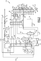
- a sixth installation is represented on the Figure 6 .
- This sixth installation 180 differs from the fifth installation 150 by the presence of a downstream dynamic expansion turbine 182 coupled to a downstream compressor 184.
- an auxiliary expansion current 186 is taken from the compressed top stream 90 from the refrigerant 38 in parallel with the withdrawal stream 92.
- the auxiliary expansion current 186 is conveyed to the downstream dynamic expansion turbine 182 to be expanded at a pressure below 40 bar and substantially equal to 15.3 bar.
- the expanded auxiliary expansion stream 188 coming from the turbine 182 is then reintroduced into the head stream 190, upstream of the first heat exchanger 20 and downstream of the second heat exchanger 28.
- the current 86 coming from the first heat exchanger 20 is separated into a first recompression fraction 121A which is sent to the first compressor 32 and to a second compression fraction 121B which is sent to the downstream compressor 184.
- the ratio of the melt flow rate of the auxiliary flash stream 186 to the compressed top stream 90 from the coolant 38 is less than 30% and is substantially between 10 and 30%.
- the installation 180 comprises a second bypass valve 192 able to send a portion of the stream 54 to the column 30 without being cooled, in particular in the second heat exchanger 28.
- a fraction of the stream 54 can therefore be withdrawn and pass through the valve 192 before being reintroduced into the fraction 56.
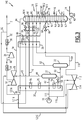
- a seventh installation 200 according to the invention is represented on the Figure 7 .
- the seventh installation comprises, as in the fourth installation 150, a downstream separator tank 152 which receives the second relaxed feed fraction 118 after passing through the second expansion turbine 112.
- the third overhead stream 156 passes into the second exchanger 28 to be cooled and partially liquefied and form a cooled reflux stream 160.
- the foot stream 154 from the downstream flask 152 is expanded in the sixth static expansion valve 128 to form a relaxed stream 158 which is introduced into a lower part of the column 30.
- the installation comprises a bypass provided with a valve 192 which makes it possible to pass a portion of the effluent 54 from the first turbine 26 directly into the column 30 without passing through the second exchanger 28.
- the seventh method is moreover implemented in a manner analogous to that of the fifth method according to the invention.
- FIG. 8 An eighth installation 210 according to the invention according to the invention is represented on the Figure 8 .
- This eighth installation 210 is intended for the implementation of an eighth method according to the invention.
- the eighth installation 210 is advantageously intended to increase the capacity of an installation of the type described in the patent US6,578,379 and comprising the first heat exchanger 20, the first separator tank 22, the second separator tank 24, the distillation column 30, the first compressor 32 coupled to the first expansion turbine 26 and the second compressor 36.
- the eighth installation 210 further comprises a second dynamic expansion turbine 112 and a third compressor 114, a downstream flask 152 for collecting the effluent from the second dynamic expansion turbine 112.
- the installation 210 further comprises an upstream heat exchanger 212, a downstream heat exchanger 214, an auxiliary distillation column 216 provided with a bottom auxiliary pump 218.
- the eighth facility 210 also includes a fourth compressor 220 interposed between two air coolers 222A, 222B.
- the eighth method according to the invention differs from the fourth method according to the invention in that the feed stream 16 is further separated into a third fraction of feed stream 224 which is introduced into the upstream heat exchanger 212, before to form with the first fraction 115 from the exchanger 20 the first fraction 42 cooled.
- the ratio of the molar flow rate of the third fraction 224 to the molar flow rate of the feed stream 16 is greater than 5%.
- the third overhead stream 156 from the downstream flask 152 is introduced into the downstream heat exchanger 214 to be cooled to a temperature below -70 ° C and form the cooled third overhead stream 160.
- the cooled third overhead stream 160 is introduced into the auxiliary column 216 at a lower stage E1.
- Column 216 has a number of theoretical stages less than the number of theoretical stages of column 30. This stage number is advantageously between 1 and 7. Auxiliary column 216 operates at a pressure substantially equal to that of the column. 30.
- the relaxed foot stream 158 obtained after expansion of the foot stream 154 in the valve 128 and the liquid foot fraction 68 obtained after expansion of the bottom fraction 64 in the valve 66 are mixed upstream of the column 30 to be introduced in the same point in the column 30.
- the two mixed streams 226 are introduced into the column 30 at a level N3 advantageously corresponding to the twelfth stage from the top of the column 30.
- the overhead vapor fraction 62 from the second separator tank 24 is introduced, after passing through the valve 70, to an average stage E2 of the auxiliary column 216 located above the stage E1.
- a first portion 227 of the fraction 52 expanded in the valve 50 is introduced into the auxiliary column 216 at a stage E3 located above the level E2.
- a second portion 228 of the fraction 52 is introduced directly into the column 30 at the level N1.
- Auxiliary column 216 produces a 230 methane-rich head auxiliary stream 230 and a foot auxiliary current 232.
- the auxiliary head stream 230 is mixed with the methane-rich head stream 84 produced by the distillation column 30.
- the foot stream 232 is pumped by the auxiliary pump 218 to form a cooled reflux stream 234 which is introduced into the column 30 at the level N5.
- the stream 234 thus constitutes a cooled reflux stream which is obtained from a portion of an effluent 118 of a dynamic expansion turbine 112, after separation of this effluent.
- the mixture 235 of the overhead streams 84 and 230 is separated into a first major fraction 236 of the overhead stream and a second minor fraction 238 of the overhead stream.
- the ratio of the molar flow rate of the majority fraction 236 to the minor fraction 238 is greater than 1.5.
- the majority fraction 236 is introduced successively into the second heat exchanger 28, then into the first heat exchanger 20, in order to form the heated head stream 86 introduced into the first compressor 32.
- the second overhead stream fraction 238 is passed through the downstream heat exchanger 214 countercurrently to the third overhead stream 156 to warm to a temperature above -50 ° C and form a second heated fraction 240 .
- the second heated fraction 240 is then separated into a return stream 242, and a compression stream 244.
- the return current 242 is reintroduced into the first head stream fraction 236, downstream of the second heat exchanger 28 and upstream of the first heat exchanger 20 to partially form the heated head stream 86.
- the recompression stream 244 is then introduced into the upstream exchanger 212 to cool the third fraction of the feed stream 224.
- the stream 244 warms to a temperature above -10 ° C to form a warmed recompression stream 246 .
- a first portion 248 of the recompression stream 246 is mixed with the first fraction of the overhead stream 236 downstream of the first heat exchanger 20 to form the heated overhead stream 86.
- a second portion 250 of the recompression stream 246 is introduced into the third compressor 114, then into the refrigerant 222A, before being recompressed in the fourth compressor 220 and introduced into the refrigerant 222B.
- the second compressed portion 252 from the refrigerant 222B has a temperature below 60 ° C and in particular substantially equal to 40 ° C and a pressure greater than 35 bar and in particular equal to 63.1 bar.
- This first compressed portion 252 is mixed with the compressed top stream 90 downstream of the tapping point of the draw stream 92 to form the methane-rich stream 12.
- the heat exchanger 28 does not receive reboiling current from the column 30.
- an auxiliary cooling stream 174 is taken in the withdrawal stream 92 upstream of the exchanger 28 as in the fifth process.
- the eighth installation 210 and the eighth method according to the invention therefore make it possible to increase the capacity of a plant of the state of the art to increase the flow rate of the supply stream 16, without having to modify the existing equipment.
- the installation and in particular by keeping the heat exchangers 20, 28, the column 30, the compressors 32, 36 and the turbine 26 identical and using the entries already present on the column 30.
- Examples of temperature, pressure, and molar flow of the various streams are given in Table 13 below, for a feed comprising in mole 2.06% nitrogen, 83.97% methane, 6.31% of ethane, 3.66% propane, 0.71% isobutane, 1.49% n-butane, 0.44% iso-pentane, 0.5% n-pentane, 0.19% % n-hexane, 0.10% n-heptane, 0.03% n-octane, and 0.5% carbon dioxide.
- Table 14 below illustrates the progressive increase in the flow rate of the feed stream 16.
- the recovery of the C2 + in the stream 14 is greater than 99% and substantially equal to 99.1%.
- the power of the compressor 36 is kept constant at 14896 kW.
- Feed rate Power of the turbine 26 Flow to the turbine 112 Power of the turbine 112 Power of compressor 220 Pressure of column 30 % kW kgmol / h kW kW bara 100 4382 0 0 0 18.0 109 4160 2000 1086 529 18.0 115 4095 3300 1832 1415 17.4 120 4131 3950 2256 2588 16.7
- the pressure of the column 30 is slightly decreased.
- the presence of the new compressor 220 keeps the power of the second compressor 36 the same, despite the increase in flow.
- the capacity of the first expansion turbine 26 has been kept constant.
- the turbine 112 is used to process the addition of capacity.
- auxiliary column 216 also prevents clogging of the column 30 during the flow increase.
- auxiliary tank 152 also avoids the problem of freezing the heavy contents in the feed stream.
- the eighth installation 210 makes it possible to treat a feed stream 16 containing more C 2 + hydrocarbons.
- Such a stream has, for example, a composition comprising in mole, 1% nitrogen, 86.25% methane, 5.78% ethane, 2.99% propane, 0.71% isobutane, 49% of n-butane, 1.28% of C 5 + hydrocarbons and 0.5% of carbon dioxide, which is the initial charge which will subsequently be increased in C 2 + , according to Table 15 below.
- the enriched composition has more than 1 mol% of C 5 + hydrocarbons.
- the eighth installation according to the invention makes it possible to retain an ethane recovery greater than 99%, in particular equal to 99.2%, a temperature and a pressure of the feed stream 16 substantially the same.
- the losses of charges allocated in the equipment, the efficiency of the trays in the column 30 and the position of the withdrawals, the maximum methane specification of the bottom stream 82 of the column 30, the efficiencies of the turbines and the compressors, the power of the second compressor 36 and the existing turbine 26 and the heat exchange coefficients of the existing exchangers 20 and 28 are kept identical.
- the recovery of C 2 + in stream 12 is greater than 99 mol%, preferably equal to 99.2 mol%.
- the power of the compressor 36 is kept constant at 13790 kW.
- the pressure of the column 30 decreases slightly with the increase of the C 2 + content , from 19.0 bars, to 18.6 bars and then to 17.8 bars.
- TABLE 15 Cutting speed 14 rich in C 2 + Power of the turbine 26 Flow to the turbine 112 Power of the turbine 112 Power of compressor 220 kgmol / h kW kgmol / h kW kW 1872 4111 0 0 0 1970 4024 950 502 0 2051 3829 1840 1005 383
- the new compressor 220 thus makes it possible to obtain a treated gas rich in methane 12 under the same conditions as in the state of the art.
- the installation comprises a second dynamic expansion turbine 112, as shown in FIGS. Figures 2 , 3 , 4 , 7 or 8 .
- the feed stream 16 is then separated into a first fraction 115 of the feed stream and a second fraction 116 of the feed stream, which travels as described above with reference to Figures 2 , 3 , 4 , 7 or 8 .
Landscapes
- Engineering & Computer Science (AREA)
- Physics & Mathematics (AREA)
- Mechanical Engineering (AREA)
- Thermal Sciences (AREA)
- General Engineering & Computer Science (AREA)
- Chemical & Material Sciences (AREA)
- Chemical Kinetics & Catalysis (AREA)
- General Chemical & Material Sciences (AREA)
- Oil, Petroleum & Natural Gas (AREA)
- Separation By Low-Temperature Treatments (AREA)
- Organic Low-Molecular-Weight Compounds And Preparation Thereof (AREA)
Claims (13)
- Verfahren zum Herstellen eines an Methan reichen Stroms (12) und eines an C2 +-Kohlenwasserstoffen reichen Stroms (14) ausgehend von einem Versorgungsstrom (16), der Kohlenwasserstoffe enthält, wobei das Verfahren die folgenden Schritte umfasst:- Trennen eines Versorgungsstroms (16) in eine erste Fraktion (115) des Versorgungsstroms und in wenigstens eine zweite Fraktion (116) des Versorgungsstroms,- Einleiten der ersten Fraktion (115) des Versorgungsstroms in einen ersten Wärmetauscher (20);- Kühlen der ersten Fraktion (115) des Versorgungsstroms in dem ersten Wärmetauscher (20);- Einleiten der ersten Fraktion des gekühlten Versorgungsstroms (42) in einen ersten Ballonabscheider (22), um einen leichten Kopfstrom (44) und einen schweren Fußstrom (45) zu erzeugen;- Unterteilen des leichten Kopfstroms (44) in eine Turbinenversorgungsfraktion (48) und in eine Kolonnenversorgungsfraktion (46);- Entspannen der Turbinenversorgungsfraktion (48) in einer ersten Turbine (26) mit dynamischer Entspannung und Einleiten wenigstens eines Teils (56; 54) der in der ersten Turbine (36) entspannten Fraktion (54) in einen mittleren Teil einer ersten Destillationskolonne (30);- Kühlen und wenigstens teilweises Kondensieren der Kolonnenversorgungsfraktion (46) in einem zweiten Wärmetauscher (28) und Entspannen und Einleiten der gekühlten Kolonnenversorgungsfraktion in einen oberen Teil der ersten Destillationskolonne (30);- Entspannen und teilweises Verdampfen des schweren Fußstroms (45) in dem ersten Wärmetauscher (20) und Einleiten des entspannten schweren Fußstroms (45) in einen zweiten Ballonabscheider (24), um eine gasförmige Kopffraktion (62) und eine flüssige Fußfraktion (64) zu erzeugen;- Entspannen der flüssigen Fußfraktion (64) und Einleiten in den mittleren Teil der ersten Destillationskolonne (30);- Abkühlen und wenigstens teilweises Kondensieren des gasförmigen Kopffraktion (62) in dem zweiten Wärmetauscher (28) und Einleiten in den oberen Teil der ersten Destillationskolonne (30);- Wiedergewinnen eines Säulenbodenstroms (82) am Fuß der ersten Destillationskolonne (30), wobei der an C2 +-Kohlenwasserstoffen reiche Strom (14) anhand des Kolonnenfußstroms (82) gebildet wird;- Wiedergewinnen und erneutes Erwärmen eines an Methan reichen Kolonnenkopfstroms (84),- Komprimieren wenigstens einer Fraktion des Kolonnenkopfstroms (84) in wenigstens einem ersten Verdichter (32), der mit der ersten Turbine (26) mit dynamische Entspannung gekoppelt ist, und in wenigstens einem zweiten Verdichter (36);- Bilden des an Methan reichen Stroms (12) ausgehend von dem wieder erwärmten und verdichteten Kolonnenkopfstroms (90);- Abgreifen eines Anzapfstroms (92) in dem Kolonnenkopfstrom (90);- Kühlen und Einleiten des gekühlten Anzapfstroms (96) in einen oberen Teil der ersten Destillationskolonne (30);wobei das Verfahren die folgenden Schritte umfasst:- Einleiten der gesamten zweiten Fraktion des Versorgungsstroms (116) in eine zweite Turbine (112) mit dynamischer Entspannung, die von der ersten Turbine (26) mit dynamischer Entspannung verschieden ist, ohne Kühlung zwischen dem Schritt des Trennens des Versorgungsstroms und dem Schritt des Einleitens der zweiten Fraktion des Versorgungsstroms in die zweite Turbine (112) mit dynamischer Entspannung,- Bilden eines gekühlten Rückflussstroms (160; 234) ausgehend von wenigstens einem Teil eines Ausflusses (118), der von einer Turbine (112) mit dynamischer Entspannung stammt, wobei die entspannte Fraktion, die von der zweiten Turbine (112) mit dynamischer Entspannung stammt, den Ausfluss bildet, der von der Turbine mit dynamischer Entspannung stammt,wobei der Ausflussteil, der von der Turbine mit dynamischer Entspannung stammt, in einem Wärmetauscher (28; 214) gekühlt und wenigstens teilweise verflüssigt wird, um den gekühlten Rückflussstrom (160; 234) zu bilden,- Einleiten des gekühlten Rückflussstroms (160; 234), der von dem Wärmetauscher (28; 214) stammt, in die erste Destillationskolonne (30).
- Verfahren nach Anspruch 1, dadurch gekennzeichnet, dass es die folgenden Schritte umfasst:- Abgreifen eines Aufkochstroms (80) in der ersten Destillationskolonne (30) auf einer Abgreifhöhe;- Herstellen einer Wärmeaustauschbeziehung zwischen dem Wiederaufkochstrom (80) und dem Teil des Ausflusses, der von einer Turbine mit dynamischer Entspannung stammt, in dem Wärmetauscher (28), um den Teil des Ausflusses, der von der Turbine mit dynamischer Entspannung stammt, zu kühlen und wenigstens teilweise zu verflüssigen, und- erneutes Einleiten des Aufkochstroms (80) in die erste Destillationskolonne (30) auf einer Höhe, die niedriger als die Abgreifhöhe ist.
- Verfahren nach Anspruch 1 oder 2, dadurch gekennzeichnet, dass das Verfahren das Einleiten der entspannten Fraktion (54), die von der ersten Turbine (26) mit dynamischer Entspannung stammt, in den zweiten Wärmetauscher (28), um ihn dort zu kühlen und teilweise zu verflüssigen, umfasst, wobei die gekühlte entspannte Fraktion einen gekühlten Hilfsrückflussstrom (56) bildet, wobei das Verfahren das Einleiten des gekühlten Hilfrückflussstroms (56) in einen mittleren Teil der ersten Destillationskolonne umfasst.
- Verfahren nach einem der vorhergehenden Ansprüche, dadurch gekennzeichnet, dass es die folgenden Schritte umfasst:- Einleiten der entspannten Fraktion (118), die von der zweiten Turbine (112) mit dynamischer Entspannung stammt, in einen stromabseitigen Ballonabscheider (152), um einen dritten gasförmigen Kopfstrom (156) und einen dritten flüssigen Fußstrom (154) zu bilden,- Kühlen des dritten gasförmigen Kopfstroms (156) in dem Wärmetauscher (28; 214), um den gekühlten Rückflussstrom (160) zu bilden.
- Verfahren nach Anspruch 4, dadurch gekennzeichnet, dass der dritte gasförmige Kopfstrom (156) nach dem Kühlen in eine Hilfsdestillationskolonne (216) eingeleitet wird, wobei der gekühlte Rückflussstrom (234) ausgehend von dem Fußstrom (232) der Hilfsdestillationskolonne (216) gebildet wird.
- Verfahren nach einem der vorhergehenden Ansprüche, dadurch gekennzeichnet, dass es die folgenden Schritte umfasst:- Abgreifen einer sekundären Verdichtungsfraktion (121B) in dem an Methan (86) reichen Kolonnenkopfstrom vor dem Durchgang des an Methan (86) reichen Kolonnenkopfstroms durch den ersten Verdichter (32),- Schicken der Verdichtungsfraktion (121B) durch einen dritten Verdichter (114), der mit der zweiten Turbine (112) mit dynamischer Entspannung gekoppelt ist;- Einleiten der verdichteten sekundären Verdichtungsfraktion (121C), die von dem dritten Verdichter (114) stammt, in den verdichteten Kolonnenkopfstrom stromabseitig von dem ersten Verdichter (32).
- Verfahren nach einem der vorhergehenden Ansprüche, dadurch gekennzeichnet, dass es die folgenden Schritte umfasst:- Abgreifen eines Unterstützungskühlungsstroms (174) in dem an Methan reichen Kolonnenkopfstrom (84, 86, 88, 90) oder in einem Strom (92), der ausgehend von dem an Methan reichen Kolonnenkopfstrom (84, 86, 88, 90) gebildet wird,- Entspannen und Einleiten des entspannten Unterstützungskühlungsstroms (176) in einen Strom (42, 48), der stromaufseitig von der ersten Entspannungsturbine (26) zirkuliert, vorteilhaft in der ersten Fraktion des gekühlten Versorgungsstroms (42) oder in der Turbinenversorgungsfraktion (48).
- Verfahren nach einem der vorhergehenden Ansprüche, dadurch gekennzeichnet, dass es die folgenden Schritte umfasst:- Schicken des an Methan reichen Kolonnenkopfstroms (84) in den ersten Wärmetauscher (20);- Abgreifen eines Hilfsentspannungsstroms (121B) in dem an Methan reichen Kolonnenkopfstrom (84) nach seinem Durchgang durch den ersten Wärmetauscher (20);- dynamisches Entspannen des Hilfsentspannungsstroms (121B) in der Hilfsturbine (182) mit dynamischer Entspannung;- Einleiten des entspannten Stroms (121C), der von der Hilfsturbine (182) mit dynamischer Entspannung stammt, in den an Methan reichen Kolonnenkopfstrom (84), bevor er in den ersten Wärmetauscher (20) eintritt.
- Verfahren nach einem der vorhergehenden Ansprüche, dadurch gekennzeichnet, dass der zweite Verdichter (36) eine erste Verdichtungsstufe (36A), wenigstens eine zweite Verdichtungsstufe (36B) und eine Kühleinrichtung (38A), die zwischen die erste Verdichtungsstufe (36A) und die zweite Verdichtungsstufe (36bB) eingefügt ist, umfasst, wobei das Verfahren einen Schritt des Schickens des verdichteten Kolonnenkopfstroms (88), der von dem ersten Verdichter (32) stammt, nacheinander durch die erste Verdichtungsstufe (36A), durch die Kühleinrichtung (38A) und dann durch die zweite Verdichtungsstufe (36B) umfasst.
- Verfahren nach einem der vorhergehenden Ansprüche, dadurch gekennzeichnet, dass der Teil des Ausflusses (54; 118), der von der Turbine mit dynamischer Entspannung stammt, der Kolonnenkopfstrom (84), die Kolonnenversorgungsfraktion (46) und die gasförmige Kopffraktion (62) in dem zweiten Wärmetauscher (28) in einer Wärmeaustauschbeziehung angeordnet sind.
- Verfahren nach einem der Ansprüche 1 bis 9, dadurch gekennzeichnet, dass wenigstens eine Fraktion (238) des Kolonnenkopfstroms (84) und des Teils des Ausflusses (118) von der Turbine mit dynamischer Entspannung in einem stromabseitigen Wärmetauscher (214), der von dem zweiten Wärmetauscher (28) verschieden ist, in einer Wärmeaustauschbeziehung angeordnet sind.
- Anlage für die Produktion eines an Methan reichen Stroms (12) und eines an C2 +-Kohlenwasserstoffen reichen Stroms (14) ausgehend von einem Versorgungsstrom (16), der Kohlenwasserstoffe enthält, des Typs, der Folgendes umfasst:- Mittel zum Trennen des Versorgungsstroms (16) in eine erste Fraktion (115) des Versorgungsstroms und in wenigstens eine zweite Fraktion (116) des Versorgungsstroms,- einen ersten Wärmetauscher (20), um wenigstens die erste Fraktion (115) des Versorgungsstroms (16) zu kühlen;- Mittel zum Einleiten der ersten Fraktion (115) des Versorgungsstroms in den ersten Wärmetauscher (20);- einen ersten Ballonabscheider (22) und Mittel zum Einleiten der ersten Fraktion des gekühlten Versorgungsstroms (42) in den ersten Ballonabscheider (22), um einen leichten Kopfstrom (44) und einen schweren Fußstrom (45) zu erzeugen;- Mittel zum Unterteilen des leichten Kopfstroms (44) in eine Fraktion (48) für die Versorgung einer Turbine und in eine Fraktion (46) für die Versorgung einer Kolonne;- eine erste Destillationskolonne (30);- Mittel zum Entspannen der Turbinenversorgungsfraktion (48), die eine erste Turbine (26) mit dynamischer Entspannung und Mittel zum Einleiten wenigstens eines Teils (56) der entspannten Fraktion (54), die in der ersten Turbine (26) entspannt wurde, in einen mittleren Teil der ersten Destillationskolonne (30);- Mittel zum Kühlen und wenigstens teilweisen Kondensieren der Kolonnenversorgungsfraktion (46), die einen zweiten Wärmetauscher (28) und Mittel zum Entspannen und Einleiten der gekühlten Kolonnenversorgungsfraktion (52) in einen oberen Teil der ersten Destillationskolonne (30) umfassen;- Mittel (58) zum Entspannen und Mittel zum teilweisen Verdampfen des schweren Fußstroms (60), die den ersten Wärmetauscher (20) umfassen;- einen zweiten Ballonabscheider (24) und Mittel zum Einleiten des schweren Fußstroms (60) in den zweiten Ballonabscheider, um eine gasförmige Kopffraktion (62) und eine flüssige Fußfraktion (64) zu erzeugen;- Mittel (66) zum Entspannen des flüssigen Fußteils (64) und Mittel zum Einleiten in den mittleren Teil der ersten Destillationskolonne (30);- Mittel zum Kühlen und wenigstens teilweisen Kondensieren der gasförmigen Kopffraktion (62), die den zweiten Wärmetauscher (28) und Mittel zum Einleiten der gasförmigen Kopffraktion (62) in den oberen Teil der ersten Destillationskolonne (30) umfassen;- Mittel zum Wiedergewinnen eines Kolonnenbodenstroms (62) am Fuß der ersten Destillationskolonne (30) und Mittel zum Bilden des an C2 +-Kohlenwasserstoffen reichen Stroms ausgehend von dem Kolonnenbodenstrom (82);- Mittel zum Wiedergewinnen und erneuten Erwärmen eines an Methan reichen Kolonnenkopfstroms (84) am Kopf der ersten Destillationskolonne (30);- Mittel zum Komprimieren wenigstens einer Fraktion des Kolonnenkopfstroms, die wenigstens einen ersten Verdichter (32), der mit der ersten Turbine (26) mit dynamischer Entspannung gekoppelt ist, und wenigstens einen zweiten Verdichter (36) umfassen;- Mittel zum Bilden des an Methan reichen Stroms (12) ausgehend von dem erneut erwärmten und verdichteten Kolonnenkopfstrom (90);- Mittel zum Abgreifen in dem Kolonnenkopfstrom (84, 86, 88, 90) eines Anzapfstroms (92),- Mittel zum Kühlen und Einleiten des gekühlten Anzapfstroms in einen oberen Teil der ersten Destillationskolonne (30);wobei die Anlage Folgendes umfasst:eine zweite Turbine (112) mit dynamischer Entspannung, die von der ersten Turbine (26) mit dynamischer Entspannung verschieden ist,- Mittel zum Einleiten der gesamten zweiten Fraktion des Versorgungsstroms (116) in die zweite Turbine (112) mit dynamischer Entspannung,- Mittel zum Bilden eines gekühlten Rückflussstroms (160; 234) ausgehend von wenigstens einem Teil eines Ausflusses (118), der von einer Turbine (112) mit dynamischer Entspannung stammt, wobei die entspannte Fraktion (118), die von der zweiten Turbine (112) mit dynamischer Entspannung stammt, den Ausfluss (118) bildet, der von der Turbine mit dynamischer Entspannung stammt,wobei der Teil des Ausflusses, der von der Turbine mit dynamischer Entspannung stammt, in einem Wärmetauscher (28; 214) gekühlt und wenigstens teilweise verflüssigt wird, um den gekühlten Rückflussstrom (160; 234) zu bilden,- Mittel zum Einleiten des gekühlten Rückflussstroms (56; 160; 234), der von dem Wärmetauscher (28; 214) stammt, in die erste Destillationskolonne (30),wobei die Mittel zum Einleiten der gesamten zweiten Fraktion des Versorgungsstroms (116) in die zweite Turbine (112) mit dynamischer Entspannung ohne Kühlung zwischen den Mitteln zum Trennen des Versorgungsstroms und den Mitteln zum Einleiten der zweiten Fraktion des Versorgungsstroms in die zweite Turbine (112) mit dynamischer Entspannung konfiguriert sind.
- Anlage nach Anspruch 12, dadurch gekennzeichnet, dass sie Mittel zum Einleiten der entspannten Fraktion (54), die von der ersten Turbine (26) mit dynamischer Entspannung stammt, in den zweiten Wärmetauscher (28), damit er dort gekühlt und teilweise verflüssigt wird, umfasst, wobei die gekühlte entspannte Fraktion einen gekühlten Hilfsrückflussstrom (56) bildet, wobei die Anlage Mittel zum Einleiten des gekühlten Hilfrückflussstroms (56) in die erste Destillationskolonne umfasst.
Applications Claiming Priority (2)
| Application Number | Priority Date | Filing Date | Title |
|---|---|---|---|
| FR0954781A FR2947897B1 (fr) | 2009-07-09 | 2009-07-09 | Procede de production d'un courant riche en methane et d'un courant riche en hydrocarbures en c2+, et installation associee. |
| PCT/FR2010/051437 WO2011004123A2 (fr) | 2009-07-09 | 2010-07-07 | Procédé de production d'un courant riche en méthane et d'un courant riche en hydrocarbures en c2+, et installation associée |
Publications (2)
| Publication Number | Publication Date |
|---|---|
| EP2452140A2 EP2452140A2 (de) | 2012-05-16 |
| EP2452140B1 true EP2452140B1 (de) | 2019-04-10 |
Family
ID=42123187
Family Applications (1)
| Application Number | Title | Priority Date | Filing Date |
|---|---|---|---|
| EP10742221.4A Active EP2452140B1 (de) | 2009-07-09 | 2010-07-07 | Verfahren zur herstellung eines methanreichen stroms und c2+kohlenwasserstoffreichen stroms und zugehörige anlage |
Country Status (9)
| Country | Link |
|---|---|
| US (2) | US9310128B2 (de) |
| EP (1) | EP2452140B1 (de) |
| AR (1) | AR077652A1 (de) |
| BR (1) | BR112012000404B1 (de) |
| CA (1) | CA2767502C (de) |
| DK (1) | DK201070320A (de) |
| FR (1) | FR2947897B1 (de) |
| MX (1) | MX353746B (de) |
| WO (1) | WO2011004123A2 (de) |
Families Citing this family (21)
| Publication number | Priority date | Publication date | Assignee | Title |
|---|---|---|---|---|
| FR2966578B1 (fr) | 2010-10-20 | 2014-11-28 | Technip France | Procede simplifie de production d'un courant riche en methane et d'une coupe riche en hydrocarbures en c2+ a partir d'un courant de gaz naturel de charge, et installation associee. |
| FR2969745B1 (fr) * | 2010-12-27 | 2013-01-25 | Technip France | Procede de production d'un courant riche en methane et d'un courant riche en hydrocarbures en c2+ et installation associee. |
| FR2970258B1 (fr) * | 2011-01-06 | 2014-02-07 | Technip France | Procede de production d'une coupe riche en hydrocarbures en c3+ et d'un courant riche en methane et ethane a partir d'un courant d'alimentation riche en hydrocarbures et installation associee. |
| US20130074542A1 (en) * | 2011-09-25 | 2013-03-28 | Mehdi Mehrpooya | System and method for recovering natural gas liquids with auto refrigeration system |
| DE102013013883A1 (de) * | 2013-08-20 | 2015-02-26 | Linde Aktiengesellschaft | Kombinierte Abtrennung von Schwer- und Leichtsiedern aus Erdgas |
| FR3012150B1 (fr) | 2013-10-23 | 2016-09-02 | Technip France | Procede de fractionnement d'un courant de gaz craque, mettant en oeuvre un courant de recycle intermediaire, et installation associee |
| EP3060865A1 (de) * | 2013-10-25 | 2016-08-31 | Air Products and Chemicals, Inc. | Reinigung von kohlendioxid |
| WO2015158395A1 (en) * | 2014-04-17 | 2015-10-22 | Statoil Petroleum As | Extraction of natural gas liquids and cooling of treated recompressed gas |
| RU2570736C1 (ru) * | 2014-07-18 | 2015-12-10 | Публичное акционерное общество "Газпром" | Способ переработки природного или попутного нефтяного газа |
| US20160069610A1 (en) * | 2014-09-04 | 2016-03-10 | Ortloff Engineers, Ltd. | Hydrocarbon gas processing |
| US10808999B2 (en) | 2014-09-30 | 2020-10-20 | Dow Global Technologies Llc | Process for increasing ethylene and propylene yield from a propylene plant |
| EP3040405A1 (de) | 2014-12-30 | 2016-07-06 | Technip France | Verfahren zur Verbesserung der Proplyenrückgewinnung von fluidkatalytischer Krackereinheit |
| FR3042983B1 (fr) * | 2015-11-03 | 2017-10-27 | Air Liquide | Reflux de colonnes de demethanisation |
| RU2703249C1 (ru) * | 2015-12-18 | 2019-10-15 | Бектел Гидрокарбон Текнолоджи Солушенз, Инк. | Системы и способы для извлечения целевых легких углеводородов из газообразных отходов рафинирования с использованием турбодетандера в оконечной части систем |
| DE102016003305A1 (de) * | 2016-03-17 | 2017-09-21 | Linde Aktiengesellschaft | Verfahren zum Abtrennen einer ethanreichen Fraktion aus Erdgas |
| CN105797417B (zh) * | 2016-04-29 | 2018-07-06 | 大连德泽药业有限公司 | 监控温度制备高纯度馏分的分馏装置、方法以及系统 |
| GB2562692B (en) * | 2016-11-18 | 2022-07-13 | Costain Oil Gas & Process Ltd | Hydrocarbon separation process and apparatus |
| RU2763101C2 (ru) * | 2017-09-06 | 2021-12-27 | Линде Инжиниринг Норт Америка, Инк. | Способы холодоснабжения в установках для извлечения газоконденсатных жидкостей |
| US11815308B2 (en) * | 2019-09-19 | 2023-11-14 | ExxonMobil Technology and Engineering Company | Pretreatment and pre-cooling of natural gas by high pressure compression and expansion |
| US20210088274A1 (en) * | 2019-09-19 | 2021-03-25 | Exxonmobil Upstream Research Company | Pretreatment, Pre-Cooling, and Condensate Recovery of Natural Gas By High Pressure Compression and Expansion |
| JP7453952B2 (ja) | 2021-11-10 | 2024-03-21 | 一哉 上原 | アスピレータ減圧手段を用いる減圧タービン発電システム |
Family Cites Families (11)
| Publication number | Priority date | Publication date | Assignee | Title |
|---|---|---|---|---|
| US2823523A (en) * | 1956-03-26 | 1958-02-18 | Inst Gas Technology | Separation of nitrogen from methane |
| NL283490A (de) * | 1961-09-22 | 1900-01-01 | ||
| US4687499A (en) * | 1986-04-01 | 1987-08-18 | Mcdermott International Inc. | Process for separating hydrocarbon gas constituents |
| US5265427A (en) * | 1992-06-26 | 1993-11-30 | Exxon Production Research Company | Refrigerant recovery scheme |
| US5555748A (en) * | 1995-06-07 | 1996-09-17 | Elcor Corporation | Hydrocarbon gas processing |
| US5983664A (en) * | 1997-04-09 | 1999-11-16 | Elcor Corporation | Hydrocarbon gas processing |
| US6244070B1 (en) * | 1999-12-03 | 2001-06-12 | Ipsi, L.L.C. | Lean reflux process for high recovery of ethane and heavier components |
| GB0000327D0 (en) * | 2000-01-07 | 2000-03-01 | Costain Oil Gas & Process Limi | Hydrocarbon separation process and apparatus |
| FR2817766B1 (fr) * | 2000-12-13 | 2003-08-15 | Technip Cie | Procede et installation de separation d'un melange gazeux contenant du methane par distillation,et gaz obtenus par cette separation |
| US6526777B1 (en) * | 2001-04-20 | 2003-03-04 | Elcor Corporation | LNG production in cryogenic natural gas processing plants |
| WO2008002592A2 (en) * | 2006-06-27 | 2008-01-03 | Fluor Technologies Corporation | Ethane recovery methods and configurations |
-
2009
- 2009-07-09 FR FR0954781A patent/FR2947897B1/fr not_active Expired - Fee Related
-
2010
- 2010-07-07 EP EP10742221.4A patent/EP2452140B1/de active Active
- 2010-07-07 CA CA2767502A patent/CA2767502C/fr active Active
- 2010-07-07 BR BR112012000404-2A patent/BR112012000404B1/pt active IP Right Grant
- 2010-07-07 US US12/831,362 patent/US9310128B2/en active Active
- 2010-07-07 MX MX2012000474A patent/MX353746B/es active IP Right Grant
- 2010-07-07 WO PCT/FR2010/051437 patent/WO2011004123A2/fr active Application Filing
- 2010-07-08 AR ARP100102474A patent/AR077652A1/es active IP Right Grant
- 2010-07-08 DK DKPA201070320A patent/DK201070320A/en not_active Application Discontinuation
-
2015
- 2015-06-23 US US14/747,417 patent/US9823015B2/en active Active
Non-Patent Citations (1)
| Title |
|---|
| None * |
Also Published As
| Publication number | Publication date |
|---|---|
| CA2767502A1 (fr) | 2011-01-13 |
| DK201070320A (en) | 2011-01-10 |
| MX353746B (es) | 2018-01-26 |
| AR077652A1 (es) | 2011-09-14 |
| EP2452140A2 (de) | 2012-05-16 |
| FR2947897A1 (fr) | 2011-01-14 |
| WO2011004123A2 (fr) | 2011-01-13 |
| CA2767502C (fr) | 2017-09-12 |
| US20160370109A9 (en) | 2016-12-22 |
| US20110005273A1 (en) | 2011-01-13 |
| US9823015B2 (en) | 2017-11-21 |
| BR112012000404B1 (pt) | 2023-10-31 |
| FR2947897B1 (fr) | 2014-05-09 |
| BR112012000404A2 (pt) | 2016-04-05 |
| WO2011004123A3 (fr) | 2014-05-01 |
| US9310128B2 (en) | 2016-04-12 |
| US20150292798A1 (en) | 2015-10-15 |
| MX2012000474A (es) | 2012-01-27 |
Similar Documents
| Publication | Publication Date | Title |
|---|---|---|
| EP2452140B1 (de) | Verfahren zur herstellung eines methanreichen stroms und c2+kohlenwasserstoffreichen stroms und zugehörige anlage | |
| EP2659211B1 (de) | Verfahren zur herstellung eines methanreichen stroms und eines c2+kohlenwasserstoffreichen stroms sowie zugehörige anlage | |
| EP2422152B1 (de) | Verfahren zur herstellung eines methanreichen stroms und einer c2+-kohlenwasserstoffreichen fraktion aus einem erdgaseinsatzstrom und entsprechende einrichtung | |
| EP2344821B1 (de) | Verfahren zur erzeugung von flüssigen und gasförmigen stickstoffströmen, heliumreicher, gasförmiger strom und stickstoffabgereicherter kohlenwasserstoffstrom und zugehörige anlage | |
| EP2205920B1 (de) | Verfahren zur verflüssigung von erdgas mit hochdruckfraktionierung | |
| KR102243894B1 (ko) | 천연 가스의 액화 전 전처리 | |
| WO2011135538A2 (fr) | Procede de traitement d'un gaz naturel contenant du dioxyde de carbone | |
| CA2756632C (fr) | Procede de traitement d'un gaz naturel de charge pour obtenir un gaz naturel traite et une coupe d'hydrocarbures en c5+, et installation associee | |
| EP2630428B1 (de) | Vereinfachtes verfahren zur erzeugung eines methanreichen stroms und einer c2+kohlenwasserstoffreichen fraktion aus einem erdgaszustrom und entsprechende anlage | |
| CA2823900C (fr) | Procede de production d'une coupe riche en hydrocarbures c3+ et d'un courant riche en methane et ethane | |
| EP3252408B1 (de) | Verfahren zur reinigung von erdgas und zur verflüssigung von kohlendioxid | |
| FR2928720A1 (fr) | Procede de pretraitement d'un gaz naturel pour retirer le dioxyde de carbone | |
| WO2018055264A1 (fr) | Procédé de purification de gaz naturel à liquéfier | |
| EP4244557A1 (de) | Verfahren zur extraktion von ethan aus einem anfänglichen erdgasstrom und entsprechende anlage | |
| WO2020021633A1 (ja) | 天然ガス処理装置及び天然ガス処理方法 | |
| WO2020212669A1 (fr) | Procédé d'extraction d'azote d'un courant de gaz naturel ou de bio-méthane contenant des gaz acides |
Legal Events
| Date | Code | Title | Description |
|---|---|---|---|
| PUAI | Public reference made under article 153(3) epc to a published international application that has entered the european phase |
Free format text: ORIGINAL CODE: 0009012 |
|
| 17P | Request for examination filed |
Effective date: 20120109 |
|
| AK | Designated contracting states |
Kind code of ref document: A2 Designated state(s): AL AT BE BG CH CY CZ DE DK EE ES FI FR GB GR HR HU IE IS IT LI LT LU LV MC MK MT NL NO PL PT RO SE SI SK SM TR |
|
| DAX | Request for extension of the european patent (deleted) | ||
| R17D | Deferred search report published (corrected) |
Effective date: 20140501 |
|
| GRAP | Despatch of communication of intention to grant a patent |
Free format text: ORIGINAL CODE: EPIDOSNIGR1 |
|
| STAA | Information on the status of an ep patent application or granted ep patent |
Free format text: STATUS: GRANT OF PATENT IS INTENDED |
|
| INTG | Intention to grant announced |
Effective date: 20181030 |
|
| GRAS | Grant fee paid |
Free format text: ORIGINAL CODE: EPIDOSNIGR3 |
|
| GRAA | (expected) grant |
Free format text: ORIGINAL CODE: 0009210 |
|
| STAA | Information on the status of an ep patent application or granted ep patent |
Free format text: STATUS: THE PATENT HAS BEEN GRANTED |
|
| AK | Designated contracting states |
Kind code of ref document: B1 Designated state(s): AL AT BE BG CH CY CZ DE DK EE ES FI FR GB GR HR HU IE IS IT LI LT LU LV MC MK MT NL NO PL PT RO SE SI SK SM TR |
|
| REG | Reference to a national code |
Ref country code: GB Ref legal event code: FG4D Free format text: NOT ENGLISH |
|
| REG | Reference to a national code |
Ref country code: CH Ref legal event code: EP Ref country code: AT Ref legal event code: REF Ref document number: 1119254 Country of ref document: AT Kind code of ref document: T Effective date: 20190415 |
|
| REG | Reference to a national code |
Ref country code: IE Ref legal event code: FG4D Free format text: LANGUAGE OF EP DOCUMENT: FRENCH |
|
| REG | Reference to a national code |
Ref country code: DE Ref legal event code: R096 Ref document number: 602010058150 Country of ref document: DE |
|
| REG | Reference to a national code |
Ref country code: RO Ref legal event code: EPE |
|
| REG | Reference to a national code |
Ref country code: NL Ref legal event code: MP Effective date: 20190410 |
|
| REG | Reference to a national code |
Ref country code: LT Ref legal event code: MG4D |
|
| REG | Reference to a national code |
Ref country code: AT Ref legal event code: MK05 Ref document number: 1119254 Country of ref document: AT Kind code of ref document: T Effective date: 20190410 |
|
| REG | Reference to a national code |
Ref country code: NO Ref legal event code: T2 Effective date: 20190410 |
|
| PG25 | Lapsed in a contracting state [announced via postgrant information from national office to epo] |
Ref country code: NL Free format text: LAPSE BECAUSE OF FAILURE TO SUBMIT A TRANSLATION OF THE DESCRIPTION OR TO PAY THE FEE WITHIN THE PRESCRIBED TIME-LIMIT Effective date: 20190410 |
|
| PG25 | Lapsed in a contracting state [announced via postgrant information from national office to epo] |
Ref country code: FI Free format text: LAPSE BECAUSE OF FAILURE TO SUBMIT A TRANSLATION OF THE DESCRIPTION OR TO PAY THE FEE WITHIN THE PRESCRIBED TIME-LIMIT Effective date: 20190410 Ref country code: SE Free format text: LAPSE BECAUSE OF FAILURE TO SUBMIT A TRANSLATION OF THE DESCRIPTION OR TO PAY THE FEE WITHIN THE PRESCRIBED TIME-LIMIT Effective date: 20190410 Ref country code: ES Free format text: LAPSE BECAUSE OF FAILURE TO SUBMIT A TRANSLATION OF THE DESCRIPTION OR TO PAY THE FEE WITHIN THE PRESCRIBED TIME-LIMIT Effective date: 20190410 Ref country code: AL Free format text: LAPSE BECAUSE OF FAILURE TO SUBMIT A TRANSLATION OF THE DESCRIPTION OR TO PAY THE FEE WITHIN THE PRESCRIBED TIME-LIMIT Effective date: 20190410 Ref country code: PT Free format text: LAPSE BECAUSE OF FAILURE TO SUBMIT A TRANSLATION OF THE DESCRIPTION OR TO PAY THE FEE WITHIN THE PRESCRIBED TIME-LIMIT Effective date: 20190910 Ref country code: LT Free format text: LAPSE BECAUSE OF FAILURE TO SUBMIT A TRANSLATION OF THE DESCRIPTION OR TO PAY THE FEE WITHIN THE PRESCRIBED TIME-LIMIT Effective date: 20190410 Ref country code: HR Free format text: LAPSE BECAUSE OF FAILURE TO SUBMIT A TRANSLATION OF THE DESCRIPTION OR TO PAY THE FEE WITHIN THE PRESCRIBED TIME-LIMIT Effective date: 20190410 |
|
| PG25 | Lapsed in a contracting state [announced via postgrant information from national office to epo] |
Ref country code: PL Free format text: LAPSE BECAUSE OF FAILURE TO SUBMIT A TRANSLATION OF THE DESCRIPTION OR TO PAY THE FEE WITHIN THE PRESCRIBED TIME-LIMIT Effective date: 20190410 Ref country code: GR Free format text: LAPSE BECAUSE OF FAILURE TO SUBMIT A TRANSLATION OF THE DESCRIPTION OR TO PAY THE FEE WITHIN THE PRESCRIBED TIME-LIMIT Effective date: 20190711 Ref country code: LV Free format text: LAPSE BECAUSE OF FAILURE TO SUBMIT A TRANSLATION OF THE DESCRIPTION OR TO PAY THE FEE WITHIN THE PRESCRIBED TIME-LIMIT Effective date: 20190410 Ref country code: BG Free format text: LAPSE BECAUSE OF FAILURE TO SUBMIT A TRANSLATION OF THE DESCRIPTION OR TO PAY THE FEE WITHIN THE PRESCRIBED TIME-LIMIT Effective date: 20190710 |
|
| PG25 | Lapsed in a contracting state [announced via postgrant information from national office to epo] |
Ref country code: AT Free format text: LAPSE BECAUSE OF FAILURE TO SUBMIT A TRANSLATION OF THE DESCRIPTION OR TO PAY THE FEE WITHIN THE PRESCRIBED TIME-LIMIT Effective date: 20190410 Ref country code: IS Free format text: LAPSE BECAUSE OF FAILURE TO SUBMIT A TRANSLATION OF THE DESCRIPTION OR TO PAY THE FEE WITHIN THE PRESCRIBED TIME-LIMIT Effective date: 20190810 |
|
| REG | Reference to a national code |
Ref country code: DE Ref legal event code: R097 Ref document number: 602010058150 Country of ref document: DE |
|
| PG25 | Lapsed in a contracting state [announced via postgrant information from national office to epo] |
Ref country code: CZ Free format text: LAPSE BECAUSE OF FAILURE TO SUBMIT A TRANSLATION OF THE DESCRIPTION OR TO PAY THE FEE WITHIN THE PRESCRIBED TIME-LIMIT Effective date: 20190410 Ref country code: DK Free format text: LAPSE BECAUSE OF FAILURE TO SUBMIT A TRANSLATION OF THE DESCRIPTION OR TO PAY THE FEE WITHIN THE PRESCRIBED TIME-LIMIT Effective date: 20190410 Ref country code: EE Free format text: LAPSE BECAUSE OF FAILURE TO SUBMIT A TRANSLATION OF THE DESCRIPTION OR TO PAY THE FEE WITHIN THE PRESCRIBED TIME-LIMIT Effective date: 20190410 Ref country code: SK Free format text: LAPSE BECAUSE OF FAILURE TO SUBMIT A TRANSLATION OF THE DESCRIPTION OR TO PAY THE FEE WITHIN THE PRESCRIBED TIME-LIMIT Effective date: 20190410 |
|
| REG | Reference to a national code |
Ref country code: DE Ref legal event code: R119 Ref document number: 602010058150 Country of ref document: DE |
|
| PLBE | No opposition filed within time limit |
Free format text: ORIGINAL CODE: 0009261 |
|
| STAA | Information on the status of an ep patent application or granted ep patent |
Free format text: STATUS: NO OPPOSITION FILED WITHIN TIME LIMIT |
|
| PG25 | Lapsed in a contracting state [announced via postgrant information from national office to epo] |
Ref country code: IT Free format text: LAPSE BECAUSE OF FAILURE TO SUBMIT A TRANSLATION OF THE DESCRIPTION OR TO PAY THE FEE WITHIN THE PRESCRIBED TIME-LIMIT Effective date: 20190410 Ref country code: SM Free format text: LAPSE BECAUSE OF FAILURE TO SUBMIT A TRANSLATION OF THE DESCRIPTION OR TO PAY THE FEE WITHIN THE PRESCRIBED TIME-LIMIT Effective date: 20190410 Ref country code: MC Free format text: LAPSE BECAUSE OF FAILURE TO SUBMIT A TRANSLATION OF THE DESCRIPTION OR TO PAY THE FEE WITHIN THE PRESCRIBED TIME-LIMIT Effective date: 20190410 |
|
| REG | Reference to a national code |
Ref country code: CH Ref legal event code: PL |
|
| 26N | No opposition filed |
Effective date: 20200113 |
|
| PG25 | Lapsed in a contracting state [announced via postgrant information from national office to epo] |
Ref country code: TR Free format text: LAPSE BECAUSE OF FAILURE TO SUBMIT A TRANSLATION OF THE DESCRIPTION OR TO PAY THE FEE WITHIN THE PRESCRIBED TIME-LIMIT Effective date: 20190410 |
|
| REG | Reference to a national code |
Ref country code: BE Ref legal event code: MM Effective date: 20190731 |
|
| PG25 | Lapsed in a contracting state [announced via postgrant information from national office to epo] |
Ref country code: DE Free format text: LAPSE BECAUSE OF NON-PAYMENT OF DUE FEES Effective date: 20200201 |
|
| PG25 | Lapsed in a contracting state [announced via postgrant information from national office to epo] |
Ref country code: SI Free format text: LAPSE BECAUSE OF FAILURE TO SUBMIT A TRANSLATION OF THE DESCRIPTION OR TO PAY THE FEE WITHIN THE PRESCRIBED TIME-LIMIT Effective date: 20190410 Ref country code: LI Free format text: LAPSE BECAUSE OF NON-PAYMENT OF DUE FEES Effective date: 20190731 Ref country code: BE Free format text: LAPSE BECAUSE OF NON-PAYMENT OF DUE FEES Effective date: 20190731 Ref country code: LU Free format text: LAPSE BECAUSE OF NON-PAYMENT OF DUE FEES Effective date: 20190707 Ref country code: CH Free format text: LAPSE BECAUSE OF NON-PAYMENT OF DUE FEES Effective date: 20190731 |
|
| PG25 | Lapsed in a contracting state [announced via postgrant information from national office to epo] |
Ref country code: IE Free format text: LAPSE BECAUSE OF NON-PAYMENT OF DUE FEES Effective date: 20190707 |
|
| PG25 | Lapsed in a contracting state [announced via postgrant information from national office to epo] |
Ref country code: CY Free format text: LAPSE BECAUSE OF FAILURE TO SUBMIT A TRANSLATION OF THE DESCRIPTION OR TO PAY THE FEE WITHIN THE PRESCRIBED TIME-LIMIT Effective date: 20190410 |
|
| PG25 | Lapsed in a contracting state [announced via postgrant information from national office to epo] |
Ref country code: MT Free format text: LAPSE BECAUSE OF FAILURE TO SUBMIT A TRANSLATION OF THE DESCRIPTION OR TO PAY THE FEE WITHIN THE PRESCRIBED TIME-LIMIT Effective date: 20190410 Ref country code: HU Free format text: LAPSE BECAUSE OF FAILURE TO SUBMIT A TRANSLATION OF THE DESCRIPTION OR TO PAY THE FEE WITHIN THE PRESCRIBED TIME-LIMIT; INVALID AB INITIO Effective date: 20100707 |
|
| PG25 | Lapsed in a contracting state [announced via postgrant information from national office to epo] |
Ref country code: MK Free format text: LAPSE BECAUSE OF FAILURE TO SUBMIT A TRANSLATION OF THE DESCRIPTION OR TO PAY THE FEE WITHIN THE PRESCRIBED TIME-LIMIT Effective date: 20190410 |
|
| P01 | Opt-out of the competence of the unified patent court (upc) registered |
Effective date: 20230601 |
|
| PGFP | Annual fee paid to national office [announced via postgrant information from national office to epo] |
Ref country code: RO Payment date: 20230623 Year of fee payment: 14 Ref country code: FR Payment date: 20230622 Year of fee payment: 14 |
|
| PGFP | Annual fee paid to national office [announced via postgrant information from national office to epo] |
Ref country code: NO Payment date: 20230712 Year of fee payment: 14 Ref country code: GB Payment date: 20230622 Year of fee payment: 14 |