EP2658038A1 - Schutzvorrichtung und Verfahren zur Herstellung einer Schutzvorrichtung - Google Patents
Schutzvorrichtung und Verfahren zur Herstellung einer Schutzvorrichtung Download PDFInfo
- Publication number
- EP2658038A1 EP2658038A1 EP13001985.4A EP13001985A EP2658038A1 EP 2658038 A1 EP2658038 A1 EP 2658038A1 EP 13001985 A EP13001985 A EP 13001985A EP 2658038 A1 EP2658038 A1 EP 2658038A1
- Authority
- EP
- European Patent Office
- Prior art keywords
- housing
- cable
- housing element
- connector
- sealing element
- Prior art date
- Legal status (The legal status is an assumption and is not a legal conclusion. Google has not performed a legal analysis and makes no representation as to the accuracy of the status listed.)
- Granted
Links
Images



Classifications
-
- H—ELECTRICITY
- H01—ELECTRIC ELEMENTS
- H01R—ELECTRICALLY-CONDUCTIVE CONNECTIONS; STRUCTURAL ASSOCIATIONS OF A PLURALITY OF MUTUALLY-INSULATED ELECTRICAL CONNECTING ELEMENTS; COUPLING DEVICES; CURRENT COLLECTORS
- H01R13/00—Details of coupling devices of the kinds covered by groups H01R12/70 or H01R24/00 - H01R33/00
- H01R13/46—Bases; Cases
- H01R13/52—Dustproof, splashproof, drip-proof, waterproof, or flameproof cases
- H01R13/5205—Sealing means between cable and housing, e.g. grommet
-
- H—ELECTRICITY
- H01—ELECTRIC ELEMENTS
- H01R—ELECTRICALLY-CONDUCTIVE CONNECTIONS; STRUCTURAL ASSOCIATIONS OF A PLURALITY OF MUTUALLY-INSULATED ELECTRICAL CONNECTING ELEMENTS; COUPLING DEVICES; CURRENT COLLECTORS
- H01R13/00—Details of coupling devices of the kinds covered by groups H01R12/70 or H01R24/00 - H01R33/00
- H01R13/46—Bases; Cases
- H01R13/52—Dustproof, splashproof, drip-proof, waterproof, or flameproof cases
- H01R13/5202—Sealing means between parts of housing or between housing part and a wall, e.g. sealing rings
-
- H—ELECTRICITY
- H01—ELECTRIC ELEMENTS
- H01R—ELECTRICALLY-CONDUCTIVE CONNECTIONS; STRUCTURAL ASSOCIATIONS OF A PLURALITY OF MUTUALLY-INSULATED ELECTRICAL CONNECTING ELEMENTS; COUPLING DEVICES; CURRENT COLLECTORS
- H01R13/00—Details of coupling devices of the kinds covered by groups H01R12/70 or H01R24/00 - H01R33/00
- H01R13/46—Bases; Cases
- H01R13/52—Dustproof, splashproof, drip-proof, waterproof, or flameproof cases
- H01R13/5219—Sealing means between coupling parts, e.g. interfacial seal
- H01R13/5221—Sealing means between coupling parts, e.g. interfacial seal having cable sealing means
-
- H—ELECTRICITY
- H01—ELECTRIC ELEMENTS
- H01R—ELECTRICALLY-CONDUCTIVE CONNECTIONS; STRUCTURAL ASSOCIATIONS OF A PLURALITY OF MUTUALLY-INSULATED ELECTRICAL CONNECTING ELEMENTS; COUPLING DEVICES; CURRENT COLLECTORS
- H01R13/00—Details of coupling devices of the kinds covered by groups H01R12/70 or H01R24/00 - H01R33/00
- H01R13/46—Bases; Cases
- H01R13/502—Bases; Cases composed of different pieces
- H01R13/506—Bases; Cases composed of different pieces assembled by snap action of the parts
-
- H—ELECTRICITY
- H01—ELECTRIC ELEMENTS
- H01R—ELECTRICALLY-CONDUCTIVE CONNECTIONS; STRUCTURAL ASSOCIATIONS OF A PLURALITY OF MUTUALLY-INSULATED ELECTRICAL CONNECTING ELEMENTS; COUPLING DEVICES; CURRENT COLLECTORS
- H01R13/00—Details of coupling devices of the kinds covered by groups H01R12/70 or H01R24/00 - H01R33/00
- H01R13/58—Means for relieving strain on wire connection, e.g. cord grip, for avoiding loosening of connections between wires and terminals within a coupling device terminating a cable
- H01R13/5845—Means for relieving strain on wire connection, e.g. cord grip, for avoiding loosening of connections between wires and terminals within a coupling device terminating a cable the strain relief being achieved by molding parts around cable and connections
Definitions
- the invention relates to a protective device for a method for producing a protective device.
- Such a protection device is used to prevent damage to a connector, in particular a standardized connector, for example, when inadvertently pulled on a cable.
- the protection device prevents the penetration of solid and liquid bodies, e.g. Moisture, water, etc., so that even in a dusty or humid environment contacting errors or short circuits can be prevented within or on the standardized connector.
- a similar protection device is for example from the DE 10 2007 004 900 A1 known.
- the protection device known from this document consists of a pair of couplable housing elements, which is designed for receiving a plug connection. This protective device is separable by decoupling the housing elements, while the connector is protected in the connected state by the pair of housing elements by the connector in the coupled housing elements is at least partially received.
- the object of the invention is to provide a protective device for a connector which provides improved protection of the connector provides.
- the protection device serves to protect a connector connected to a cable.
- the protective device has a first housing element, which is coupled or can be coupled to a second housing element of the protective device.
- the first housing element at least partially receives the connector
- the second housing element receives the cable at least partially.
- the first housing element, the second housing element and the cable are connected to one another in a material-locking manner by a sealing element.
- the protection device can be assembled in two stages or steps: In a first connection stage or a first connection step, the two housing elements are coupled to one another such that they comprise the connector and a cable section. The connector and the cable are electrically connected together.
- a sealing element is inserted, through which both the first housing element, the second housing element and the cable are materially connected to one another. Due to the couplable design of the two housing elements, the two housing elements of the protection device can be coupled to each other in a simple manner and assembled. Due to the cohesive connection via or by means of the sealing element, the two housing elements are inseparably connected to each other. Thereby, the connection of the two housing elements with each other and / or with the cable is no longer separable without damage or even destruction of at least one of the components of the protective device.
- the sealing element By means of the sealing element thus a secure connection is provided, which connects the two housing elements and the cable firmly and inseparably.
- the protective device provides a safe and robust unit with a provided high strength.
- cohesive connection is understood to mean an "intimate connection" between two bodies.
- this is a direct, direct mechanical contacting in a contact area or a contact area.
- the intimate connection can be made by shrinking a peripheral body onto another enclosed body, so that the circumferential body in the contact region exerts a force or mechanical stress on the enclosed body, so that by elastic deformation of the two bodies in the contact area there is essentially no gap between the two bodies.
- the two bodies may be fused together in the contact area.
- the cohesive connection may be a chemical compound and / or a compound in which the connection partners are connected to one another by atomic and / or molecular forces. Due to the material bond, it may be possible in particular that a separation of the elements connected by means of material connection, z, B. first housing element and / or second housing element and / or cable or cable sheath only by destruction of at least one, in particular all of the connected elements is possible.
- the sealing element is at least partially injected into a cavity between the first and the second housing element.
- a cavity is formed between the first housing element and the second housing element at at least one location. This cavity is filled in the irreversible connection of the protective device with each other by the sealing element, in particular completely filled. there the cavity is at least partially formed between the first housing member, the second housing member and the cable.
- the protective device seals the connector, in particular the cable-side region of the connector from moisture-proof to IP67.
- IP67 is a generally accepted standard for defining the moisture density of an article.
- the protection device meets the requirements of IP67. This provides good moisture and dust protection.
- the protective device seals the connection region between the cable and the connector and / or the region in which the cable is passed through the protective device and the Verbding of the two housing elements from moisture-tight.
- moisture-proof is understood as meaning a leak-tightness or a barrier with respect to a fluid, in particular water or water vapor, wherein the flow or displacement of the moisture is prevented.
- a contact area between two bodies, which are in particular intimately connected to each other moisture-proof if and only if a fluid can not penetrate along the (area) contact area in the interior of the connector between connector and cable.
- the sealing element surrounds the cable and / or the second housing element at least partially and / or is cohesively thereto.
- the second housing element is designed for at least partially receiving the cable. This may mean that a part of the cable is passed through the second housing element.
- the second housing element surrounds or surrounds the cable radially from the outside.
- the sealing element is arranged so that it encloses both the cable radially from the outside to a portion of the cable, as well as a part of the second housing member.
- a statically particularly favorable connection is provided which counteracts in particular a relative movement of the sealing element and / or the second housing member relative to the cable in Jardinausbreitungsraum.
- the cable propagation direction may be parallel to an axial direction of the cable.
- the second housing element is at least partially insertable into the first housing element, wherein the sealing element is at least partially surrounded by the first housing element.
- the second housing element is designed to receive the cable.
- the second housing element is preferably arranged in the immediate vicinity of the cable.
- the first housing element for at least partially receiving the connector can be coupled to the second housing element.
- the cable can be arranged at least partially in the first housing element.
- the coupling of the first and second housing element can be effected in particular by an at least partial insertion of the second housing element into the first housing element.
- the coupled connection of the two housing elements is materially reinforced by the sealing element.
- the sealing element consists of an elastic polymer.
- an elastic polymer By an elastic polymer, a particularly cost-effective and efficient cohesive connection can be provided.
- an elastic polymer can be injected in a simple operation in a cavity between the first housing member and the second housing member.
- the sealing element is formed at least 1 mm thick between the first housing element and the second housing element.
- the sealing element is not a mere adhesive layer, but is designed as an independent component of the protective device. It is so injected between the two housing elements that there is a cavity of a minimum thickness of 1 mm distance between the first housing member and the second housing member fills.
- the sealing element has a non-negligible volume. Because the sealing element has its own volume, the sealing element can fill in (unwanted) cavities in which moisture or dust could penetrate.
- the sealing element may also be formed from 0.1 mm to 20 mm, from 0.25 mm to 5 mm thick, in particular from 1 mm to 2 mm thick.
- the second housing element has at least one injection hole, which is filled by the sealing element and which connects a region of the sealing element which surrounds the cable, and in particular is materially connected to the cable, with a region of the sealing element, which between the first Housing element and the second housing element is arranged. Due to the formation of spray holes in the second housing element, different hollow regions or cavities can be filled in the interior of the protective device during the injection of the sealing element by means of the sealing element. As a result, various components of the protective device can be connected to one another in a material-locking manner by means of the sealing element. For example, be formed not two spray holes, which are preferably opposite.
- the first housing element has a sealing lip which, in a plugged-in state of the connector, seals a plug connection of the plug connector with the socket in a moisture-proof manner to IP67.
- the sealing lip is arranged on the side of the first housing element, which is designed and provided to be connected in the insertion direction of the connector with a socket or socket. When inserting the connector, the sealing lip is brought into contact with the socket or the socket.
- the sealing lip may be formed in particular of an elastically deformable material, which is compressed during the insertion process and thus provides a tight connection.
- the sealing lip causes a seal between the connector and the socket and / or the socket.
- the protective device itself, and in particular the sealing element provides a seal between the plug and the cable.
- the sealing lip and the sealing element together cause a moisture-tight seal both the connector (in particular by the sealing lip) and the connection region between the connector and the cable (in particular by the sealing element), ie the entire connector.
- the entire plug can be moisture-proof in accordance with IP67.
- one of the first or second housing member has a receptacle into which at least a portion of the other of the first and second housing member is at least partially insertable to couple the first housing member to the second housing member.
- the receptacle and the section provide for a coupling of the two housing elements with each other. In the coupled state, the two housing elements of the protection device are connected together.
- the first housing element may be coupled to the second housing element by a positive connection. Due to the positive connection, a decoupling of the two housing elements from each other, in particular during introduction of the sealing element is avoided. This allows both a safe insertion or injection of the sealing element, as well as a force relief between the two housing elements during drying of the sealing element. Additionally or alternatively, the first housing element may be coupled to the second housing element by a non-positive connection.
- the connector is designed as a standardized industrial plug according to an industry standard or industry standard.
- the protective device according to the invention can be used in this embodiment for any standard industrial plug.
- a protection device is provided which is intended for use with an RJ plug.
- RJ stands for "registered jack", ie for an Ethernet plug, USB plug, Firewire, power plug, DVI plug. HDMI connector, etc.
- the second housing element has a cable section which encloses a section of the cable such that a contact region between the plug connector and electrical lines of the cable is formed substantially free of the sealing element. As a result, sticking and damage to the contact area during injection of the sealing element is avoided.
- At least a part of the cable can first be performed by the second housing element and the connector can be inserted into the first housing element such that it is at least partially inserted into the first housing element.
- the method is used in particular for producing a protective device for a connector according to one of claims 1 to 13.
- FIG. 1 shows a perspective view of a protective device.
- the protection device surrounds a connector 10, which is electrically and mechanically connected to a cable 20.
- the protective device has a first housing element 30, a second housing element 40 and a sealing element 50.
- the first housing element 30 surrounds the connector 10.
- the first housing member 30 encloses the connector 10 such that a contact surface 11 of the connector 10 remains completely free.
- the contact surface 11 of the connector 10 is designed and intended to be inserted into a socket or socket to provide there electrical contact between the connector 10 and the socket or socket.
- the contact surface 11 is arranged on the side of the connector 10, which faces away from the cable 30.
- the first housing member 30 leaves not only the contact surface 11 free, but also the adjacent to the contact surface 11 portion of the connector 10, which is designed and intended to be inserted into a socket or socket.
- the first housing element 30 includes the connector 10 only from a portion of the cable 30th facing and protrudes in an inserted state of the connector from the socket or the socket.
- the first housing member 30 is in mechanical contact with the connector 10 such that it holds the connector 10.
- the second housing element 40 includes a portion of the cable 20 radially from the outside, in particular the end of the cable 30, which faces the connector 10.
- the cable 20 penetrates the second housing element 40.
- the majority of the second housing element 40 is arranged in the interior of the first housing element 30.
- the sealing element 50 is injected between the cable 20 and the second housing member 40 and connects the two housing elements cohesively with each other on the cable.
- the sealing element 50 is injected into a cavity arranged between the two housing elements 30, 40 and the cable 20, whose shape is shown in more detail in the other figures.
- FIG. 2 shows the protection of the Fig. 1 in an unconnected state.
- the first housing element 30 in this case comprises the portion of the connector 10, which protrudes in a plugged into a socket or a socket state of the connector 10 from the socket or the socket.
- the first housing element 30 in this case has a cylindrical portion 33, which is designed and intended to receive a part of the second housing element 40 and a part of the cable 20.
- the cylindrical portion 33 of the first housing member 30 is formed as a receptacle for a portion of the second housing member 40. Furthermore, the cylindrical portion 33 is provided and adapted to receive the sealing member 50.
- the first housing member 30 has a shoulder 34 which rests in an inserted state of the connector 10 to the socket or socket.
- the first housing element 30 also has diametrically opposite levers 35, which extend parallel to the cable propagation direction.
- the levers 35 are connected to the first housing member 30, in particular to the shoulder 34.
- portions 32 are formed, which are provided for engagement in a rotary ring 42. In the in the Fig. 2 shown decoupled state, both the portions 32 and the end of the lever 35, on which they are arranged, formed freely suspended.
- the second housing member 40 includes a portion of the cable 20.
- the cable 20 is threaded into the interior of the second housing member 40 so that a portion of the cable 20 is radially enclosed on all sides by the second housing member 40 and mechanically contacted.
- the second housing element 40 has a cylindrical basic shape, which has a cable outlet for insertion and removal of the cable 20.
- the second housing element 40 is preferably made of a rubber or elastomer, such as FKN, HNBR, TPE, etc., to be non-positively coupled to the first housing member.
- the second housing element 40 can also be screwed and / or latched to the first housing element.
- the second housing element 40 may be connected to the first housing element by means of a positive connection.
- the protective device on a rotary ring 42 which is formed as a handle member.
- the rotary ring 42 is arranged in the lateral direction of the cable 20.
- the rotary ring 42 is formed at two diametrically opposite points with an enlarged inner diameter at which on the inside of the handle member 42 insertion portions 41 are formed.
- the insertion sections 41 serve to receive part of the levers 35, and in particular to receive the sections 32 in such a way that the levers 35 are fixed.
- the rotary ring 42 may be formed as a separate component, or be formed as part of the second housing member 40.
- the protective device of the connector 10 facing part of the second housing member 40 is inserted into the cylindrical portion 33 of the first housing member 30. Furthermore, the portions 32 of the lever 35 are brought into engagement with the insertion portions 41 of the rotary ring 42. As a result, the first housing member 30 is coupled to the second housing member 40. Subsequently, in a cavity, in particular a partially cylindrical cavity, between the first housing member 30, the second housing member 40 and the cable 20, the sealing member 50 is injected, by means of which the first housing member 30, the second housing member 40 and the cable 20 are materially interconnected , After the introduction of the sealing element 50, the protective device is inseparably connected to each other.
- connection process takes place in that first the cable 20 is contacted with the connector 10, after which the second housing element 40 is inserted into the first housing element 30 and these are coupled together.
- FIG. 3 shows a portion of the second housing member 40 without the rotary ring 42.
- the second housing member 40 has cylindrical portions which partially form a ring around the cable 20 and partially leave a cavity between the cable and the second housing member 40 for the sealing member 50.
- a substantially cylindrical cable portion 43 is formed at the end of the second housing member 40 facing the connector 10, which includes a portion of the cable 20.
- a substantially cylindrical cavity portion 44 is formed on the cable 20 facing the end of the second housing member 40 which forms a cavity between the cavity portion 44 and the cable 20, in which the sealing element 50 is injectable.
- two injection holes 46 are formed, by means of which of the Cavity portion 44 included cavity with a (radially seen) outer space of the second housing member 40 is connected. If the sealing element 50 is injected into the cavity between the cable 20 and the cavity section 44 enclosed by the cavity section 44, the sprayed material partially exits through the injection holes 46 on the outside of the second housing element 40 and sprays a cavity between the cable section 43 and the first housing element 30 ,
- the second housing element 40 When inserting the second housing element 40 into the first housing element 30, the second housing element 40 is inserted parallel to the cable propagation direction in the insertion direction of the connector 10 until the first housing element 30 abuts against a thickened stop 45 of the second housing element.
- a coupling portion 47 of the second housing member 40 by means of a coupling portion 47 of the second housing member 40, a positive and / or non-positive connection between the first housing member 30 and the second housing member 40 is provided.
- the coupling portion 47 may e.g. consist of a non-slip rubber and / or be designed as a screw portion and / or as a latching portion.
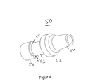
- FIG. 4 shows the sealing element 50 which is injected into the cavity between the housing elements and the cable 20.
- the sealing element 50 is formed in one piece and completely fills the cavity between the first housing element 30, the second housing element 40 and the cable 20.
- the sealing element 50 has a conical section 51 which is formed at the end of the protective device opposite the plug connector 10 and which has a cable entry for the cable 20.
- a sealing ring 52 of the sealing element 50 the outer circumference of the sealing element 50 widens almost to the outer circumference of the protective device.
- An adjoining the sealing ring 52 in the insertion direction cable enclosure 53 is as essentially cylindrical region is formed radially around the cable 20.
- the sealing element 50 merges into an intermediate region 54, which is arranged between the first housing element 30 and the second housing element 40.
- the webs 55 are formed during injection of the sealing element 50 within the injection holes 46 of the second housing member 40.
- the sealing element 50 is formed as a one-piece casting.
- the material of the sealing element 50 is liquid injected into the cavity between the first housing member 30, the second housing member 40 and the cable 20, wherein a cohesive or intimate connection with these is produced by cooling and / or curing of the material of the sealing element.
- the rotary ring 42 remains free of contact with the sealing element 50 and thus rotatable.
- the protection device remains on andWhenckbar in a socket.
- the first housing element 30 and the second housing element 40 are fixed relative to one another until the sealing element 50 has hardened.
- the first housing element 30 fixes the connector 10
- the second housing element 40 fixes the section of the cable 20 facing the connector 10.
- gripping tools can be provided which attach to the two housing elements 30, 40 and / or the cable 20 in order to fix them in their position relative to one another when injecting the sealing element 50.
- the two housing elements 30, 40 and the cable can already be fixed by their coupling, in order to allow injection and curing of the sealing element without "shaking".
- FIGS. 5A and 5B show in two sectional views in each case a section through in the Fig. 1 shown protection device with plug and cable.
- the two cutting planes are perpendicular to each other.
- the sealing element 50 is shown hatched. A synopsis of FIGS. 4 and 5 shows an embodiment of the sealing element 50.
- FIGS. 5A and 5B show further details of the protection device.
- the connector 10 is electrically and mechanically connected to the cable 20 via electrical leads 21.
- An axial direction AR of the cable 20 is also shown.
- the first housing member 30, the second housing member 40 and the sealing member 50 protect the electrical and mechanical connection between the cable 20 and the connector 10 against environmental influences such as water, dust, etc. In addition, a complete shock protection of the connection between the connector 10 and the cable 20 provided by the protection device.
- the cable portion 43 of the second housing member 40 which encloses a portion of the cable 20, terminates in the insertion direction of the connector 10 in front of a stripped portion of the cable 20, from which the electrical leads 21 for contacting the connector 10 protrude.
- the insertion direction may be parallel to the axial direction AR. This prevents the material of the sealing element 50 in the liquid, hot state contacts the contacts in the region between the connector 10 and cable 20.
- the material of the sealing member 50 is prevented in its liquid phase by the cable portion 43 of the first housing member 30 from filling the contact area.
- the contact region between the plug connector 10 and the electrical leads 21 remains substantially free of the sealing element 50.
- substantially free means that no electrical component or semiconductor component, which is arranged on the contact region, passes through the sealing element 50 is mechanically contacted.
- the levers 35 of the first housing member 30 are formed as a spring tongue and made of a metal sheet.
- the lever 35 has substantially in a central portion a tab 36 which is insertable into a corresponding slot of the first housing member 30 to attach the lever 35 to an outer periphery of the first housing member 30. Since the lever 35 is made of a resilient sheet metal, a spring-loaded lever 35 is provided in this way. For example, if pressure is exerted radially on the grip elements 37 of the lever 35 from the outside, an engagement section 38 of the lever 35 is pushed away radially outwards (for the engagement section 38 cf. Fig. 2 ).
- the engagement portion 38 is preferably rectangular.
- a socket in which the plug connector 10 can be inserted has a pair of engagement elements which can be inserted or clipped into the engagement sections 38 of the levers 35 as latching lugs. As a result, the protective device can be connected to the socket or the socket.
- the first housing member 30 further includes a sealing lip 31 to provide a moisture-tight seal between the protector and the socket.
- the sealing lip 31 is preferably made of Viton, silicone rubber or other suitable material and has a plurality of radial waves that increase the elastic malleability in the insertion direction.
- the rotary ring 42 may be formed as part of the second housing member 40, as a separate component or as part of the first housing member 30.
- the rotary ring 42nd together with its insertion sections 41 and the levers 35 serves to make contact with the protective device with the (not shown in the figures) socket or socket.
- Connectors 11 contact area 20 electric wire 21 electrical line 30 first housing element 31 sealing lip 32 section 33 cylindrical section 34 paragraph 36 flap 37 handle element 38 engaging portion 40 second housing element 41 insertion 42 rotating ring 43 cable section 44 cavity portion 45 attack 46 spiracle 47 coupling section 50 sealing element 51 conical section 52 you ring 53 cable inclusion 54 intermediate area 55 web AR axial direction
Landscapes
- Connector Housings Or Holding Contact Members (AREA)
Abstract
Description
- Die Erfindung betrifft eine Schutzvorrichtung für ein Verfahren zum Herstellen einer Schutzvorrichtung.
- Eine derartige Schutzvorrichtung dient der Verhinderung von Beschädigungen eines Steckverbinders, insbesondere eines genormten Steckverbinders, wenn beispielsweise unbeabsichtigt an einem Kabel gezogen wird. Darüber hinaus verhindert die Schutzvorrichtung das Eindringen von festen und flüssigen Körpern, z.B. Feuchtigkeit, Wasser, etc., so dass selbst in einer staubigen oder feuchten Umgebung Kontaktierungsfehler bzw. Kurzschlüsse innerhalb oder an dem genormten Steckverbinder verhindert werden können.
- Eine ähnliche Schutzvorrichtung ist beispielsweise aus der
DE 10 2007 004 900 A1 bekannt. Die aus diesem Dokument bekannte Schutzvorrichtung besteht aus einem Paar koppelbarer Gehäuseelemente, die für die Aufnahme einer Steckverbindung ausgebildet ist. Diese Schutzvorrichtung ist durch ein Entkoppeln der Gehäuseelemente trennbar, während die Steckverbindung im verbundenen Zustand durch das Paar Gehäuseelemente geschützt ist, indem die Steckverbindung in den gekoppelten Gehäuseelementen zumindest teilweise aufgenommen ist. - Moderne EDV-Anlagen, Telefonanlagen und andere elektronische Geräte und dergleichen vereinen immer mehr Funktionen und Schnittstellen auf engstem Raum. Deshalb besteht ein Bedarf für eine miniaturisierte Schutzvorrichtung, die darüber hinaus auch bei einem beengten Einbauraum auf einfache Weise betätigbar ist.
- Die Aufgabe der Erfindung besteht in der Bereitstellung einer Schutzvorrichtung für einen Steckverbinder, die einen verbesserten Schutz des Steckverbinders bereitstellt.
- Diese Aufgabe wird durch die Gegenstände der unabhängigen Ansprüche gelöst. Bevorzugte Weiterbildungen der Erfindung sind in den abhängigen Ansprüchen beschrieben.
- Gemäß einem Aspekt dient die Schutzvorrichtung zum Schutz für einen mit einem Kabel verbundenen Steckverbinder. Die Schutzvorrichtung weist ein erstes Gehäuseelement auf, das mit einem zweiten Gehäuseelement der Schutzvorrichtung gekoppelt ist bzw. koppelbar ist. Dabei nimmt das erste Gehäuseelement den Steckverbinder zumindest teilweise auf, und das zweite Gehäuseelement nimmt das Kabel zumindest teilweise auf. Das erste Gehäuseelement, das zweite Gehäuseelement und das Kabel sind durch ein Dichtelement stoffschlüssig miteinander verbunden. Mit anderen Worten ist die Schutzvorrichtung in zwei Stufen bzw. Schritten zusammenbaubar: In einer ersten Verbindungsstufe bzw. einem ersten Verbindungsschritt werden die beiden Gehäuseelemente so miteinander gekoppelt, dass sie den Steckverbinder und einen Kabelabschnitt umfassen. Der Steckverbinder und das Kabel sind elektrisch miteinander verbunden. In einer zweiten Stufe bzw. einem zweiten Verbindungsschritt wird ein Dichtelement eingefügt, durch das sowohl das erste Gehäuseelement, das zweite Gehäuseelement und das Kabel stoffschlüssig miteinander verbunden werden. Durch die koppelbare Ausbildung der beiden Gehäuseelemente sind die beiden Gehäuseelemente der Schutzvorrichtung in einfacher Weise miteinander koppelbar und zusammenbaubar. Durch die stoffschlüssige Verbindung über bzw. mittels des Dichtelements werden die beiden Gehäuseelemente untrennbar miteinander verbunden. Dadurch ist die Verbindung der beiden Gehäuseelemente miteinander und/oder mit dem Kabel nicht mehr ohne eine Beschädigung oder sogar Zerstörung zumindest eines der Bauteile der Schutzvorrichtung voneinander trennbar.
- Mittels des Dichtelements wird somit eine sichere Verbindung bereitgestellt, die die beiden Gehäuseelemente und das Kabel fest und untrennbar miteinander verbindet. Dadurch wird durch die Schutzvorrichtung eine sichere und robuste Einheit mit einer hohen Festigkeit bereitgestellt.
- Auf diese Weise kann ein Staubschutz und Feuchtigkeitsschutz geschaffen werden. Darüber hinaus wird ein vollständiger Berührungsschutz der Steckverbindung bereitgestellt, insbesondere im Anschlussbereich zwischen Steckverbinder und Kabel.
- Unter dem Begriff stoffschlüssige Verbindung wird eine "innige Verbindung" zwischen zwei Körpern verstanden. Dies ist im Sinne der Anmeldung eine direkte, unmittelbare mechanische Kontaktierung in einem Kontaktbereich bzw. einer Kontaktfläche. Insbesondere kann die innige Verbindung durch Aufschrumpfen eines umfangenden Körpers auf einen anderen umfangenen Körper erfolgen, so dass der umfangende Körper im Kontaktbereich eine Kraft bzw. mechanische Spannung auf den umfangenen Körper ausübt, so dass durch eine elastische bzw. plastische Verformung der beiden Körper im Kontaktbereich im Wesentlichen kein Zwischenraum zwischen den beiden Körpern besteht. Insbesondere können die beiden Körper im Kontaktbereich miteinander verschmolzen sein.
- Alternativ oder zusätzlich kann mit der stoffschlüssigen Verbindung eine chemische Verbindung und/oder eine Verbindung gemeint sein, bei der die Verbindungspartner durch atomare und/oder molekulare Kräfte miteinander verbunden sind. Aufgrund des Stoffschlusses kann es insbesondere möglich sein, daß eine Trennung der mittels Stoffschluss verbundenen Elemente, z,B. erstes Gehäuseelement und/oder zweites Gehäuseelement und/oder Kabel bzw. Kabelmantel nur durch Zerstörung zumindest eines, insbesondere aller der verbundenen Elemente möglich ist.
- Gemäß einer Ausführungsform ist das Dichtelement zumindest teilweise in einen Hohlraum zwischen das erste und das zweite Gehäuseelement gespritzt. Vor dem Einspritzen des Dichtelements ist zwischen dem ersten Gehäuseelement und dem zweiten Gehäuseelement an zumindest einer Stelle ein Hohlraum ausgebildet. Dieser Hohlraum wird beim irreversiblen Verbinden der Schutzvorrichtung miteinander durch das Dichtelement gefüllt, insbesondere vollständig gefüllt. Dabei ist der Hohlraum zumindest teilweise zwischen dem ersten Gehäuseelement, dem zweiten Gehäuseelement und dem Kabel ausgebildet. Durch die Anordnung eines Hohlraums im gekoppelten, aber noch nicht mittels des Dichtelements verbundenen Zustand, wird ein Einspritzen des Dichtelements vereinfacht.
- Gemäß einer Ausführungsform dichtet die Schutzvorrichtung den Steckverbinder, insbesondere den kabelseitigen Bereich des Steckverbinders feuchtigkeitsdicht nach IP67 ab. IP67 ist eine allgemein anerkannte Norm zur Definition der Feuchtigkeitsdichte eines Gegenstandes. In dieser Ausführungsform erfüllt die Schutzvorrichtung die Anforderungen von IP67. Dadurch wird ein guter Feuchtigkeits- und Staubschutz bereitgestellt. Insbesondere dichtet die Schutzvorrichtung den Verbindungsbereich zwischen dem Kabel und dem Steckverbinder und/oder den Bereich in dem das Kabel durch die Schutzvorrichtung hindurchgeführt wird sowie die Verbding der beiden Gehäuseelemente feuchtigkeitsdicht ab.
- Unter dem Begriff "feuchtigkeitsdicht" wird im Sinne der vorliegenden Anmeldung eine Dichtheit bzw. eine Barriere gegenüber einem Fluid, insbesondere Wasser oder Wasserdampf verstanden, wobei das Fließen bzw. Verlagern der Feuchtigkeit verhindert wird. Mit anderen Worten ist ein Kontaktbereich zwischen zwei Körpern, die insbesondere innig miteinander verbunden sind, genau dann feuchtigkeitsdicht, wenn ein Fluid nicht entlang des (flächigen) Kontaktbereichs in das Innere des Anschlusses zwischen Steckverbinder und Kabel eindringen kann.
- Gemäß einer Ausführungsform umschließt das Dichtelement das Kabel und/oder das zweite Gehäuseelement zumindest teilweise und/oder liegt daran stoffschlüssig an. Das zweite Gehäuseelement ist zur zumindest teilweisen Aufnahme des Kabels ausgebildet. Dies kann bedeuten, dass ein Teil des Kabels durch das zweite Gehäuseelement hindurch geführt wird. Dadurch umfasst bzw. umfängt das zweite Gehäuseelement das Kabel radial von außen. Das Dichtelement ist dabei so angeordnet, dass es sowohl das Kabel radial von außen an einem Abschnitt des Kabels umschließt, als auch einen Teil des zweiten Gehäuseelements. Durch ein zumindest teilweises Umschließen des Kabels und/oder des zweiten Gehäuseelements wird eine statisch besonders günstige Verbindung bereitgestellt, die insbesondere einer Relativbewegung des Dichtelements und/oder des zweiten Gehäuseelements relativ zum Kabel in Kabelausbreitungsrichtung entgegenwirkt. Die Kabelausbreitungsrichtung kann parallel zu einer Achsialrichtung des Kabels sein.
- Gemäß einer Ausführungsform ist das zweite Gehäuseelement zumindest teilweise in das erste Gehäuseelement einführbar, wobei das Dichtelement zumindest teilweise von dem ersten Gehäuseelement umgeben ist. Das zweite Gehäuseelement ist zur Aufnahme des Kabels ausgebildet. Dazu ist das zweite Gehäuseelement bevorzugt in unmittelbarer Kabelnähe angeordnet. Das erste Gehäuseelement zur zumindest teilweisen Aufnahme des Steckverbinders ist mit dem zweiten Gehäuseelement koppelbar. Das Kabel kann zumindest bereichsweise auch in dem ersten Gehäuseelement angeordnet sein. Die Kopplung des ersten und zweiten Gehäuseelements kann insbesondere durch ein zumindest teilweises Einführen des zweiten Gehäuseelements in das erste Gehäuseelement erfolgen. Die gekoppelte Verbindung der beiden Gehäuseelemente wird durch das Dichtelement stoffschlüssig verstärkt.
- Gemäß einer Ausführungsform besteht das Dichtelement aus einem elastischen Polymer. Durch ein elastisches Polymer kann eine besonders kostengünstige und effiziente stoffschlüssige Verbindung bereitgestellt werden. Außerdem läßt sich ein elastisches Polymer in einem einfachen Arbeitsschritt in einen Hohlraum zwischen dem ersten Gehäuseelement und dem zweiten Gehäuseelement einspritzen.
- Gemäß einer Ausführungsform ist das Dichtelement zumindest 1 mm dick zwischen dem ersten Gehäuseelement und dem zweiten Gehäuseelement ausgebildet. Das Dichtelement ist keine bloße Kleberschicht, sondern ist als eigenständiges Bauteil der Schutzvorrichtung ausgebildet. Dabei ist es derart zwischen die beiden Gehäuseelemente gespritzt, dass es einen Hohlraum einer Mindeststärke von 1 mm Abstand zwischen dem ersten Gehäuseelement und dem zweiten Gehäuseelement ausfüllt. Das Dichtelement weist ein nicht vernachlässigbares Volumen auf. Dadurch, dass das Dichtelement ein eigenes Volumen aufweist, kann das Dichtelement (unerwünschte) Hohlräume ausfüllen, in die Feuchtigkeit oder Staub eindringen könnte. Bevorzugt kann das Dichtelement auch von 0,1mm bis 20 mm, von 0,25 mm bis 5 mm dick ausgebildet sein, insbesondere von 1 mm bis 2 mm dick.
- Gemäß einer Ausführungsform weist das zweite Gehäuseelement zumindest ein Spritzloch auf, das durch das Dichtelement ausgefüllt ist und das einen Bereich des Dichtelements, der das Kabel umgibt, und insbesondere mit dem Kabel stoffschlüssig verbunden ist, mit einem Bereich des Dichtelements verbindet, der zwischen dem ersten Gehäuseelement und dem zweiten Gehäuseelement angeordnet ist. Durch die Ausbildung von Spritzlöchern im zweiten Gehäuseelement können unterschiedliche Hohlbereiche bzw. Hohlräume im Inneren der Schutzvorrichtung beim Einspritzen des Dichtelements mittels des Dichtelements ausgefüllt werden. Dadurch können verschiedene Bauteile der Schutzvorrichtung mittels des Dichtelements stoffschlüssig miteinander verbunden werden. Beispielsweise keinen zwei Spritzlöcher ausgebildet sein, die sich vorzugsweise gegenüber liegen.
- Gemäß einer Ausführungsform weist das erste Gehäuseelement eine Dichtlippe auf, die in einem in einer Buchse eingesteckten Zustand des Steckverbinders eine Steckverbindung des Steckverbinders mit der Buchse feuchtigkeitsdicht nach IP67 abdichtet. Die Dichtlippe ist dabei auf der Seite des ersten Gehäuseelements angeordnet, die dazu ausgebildet und vorgesehen ist, in Steckrichtung des Steckverbinders mit einer Buchse bzw. Steckdose verbunden zu werden. Beim Einsteckvorgang des Steckverbinders wird die Dichtlippe in Kontakt mit der Buchse bzw. der Steckdose gebracht. Dabei kann die Dichtlippe insbesondere aus einem elastisch verformbaren Material ausgebildet sein, das beim Einsteckvorgang gestaucht wird und so eine dichte Verbindung bereitstellt. Dabei bewirkt die Dichtlippe eine Abdichtung der Verbindung zwischen dem Steckverbinder und der Buchse und/oder der Steckdose. Die Schutzvorrichtung selber, und insbesondere das Dichtelement, sorgt für eine Abdichtung zwischen dem Stecker und dem Kabel. Die Dichtlippe und das Dichtelement bewirken zusammen eine feuchtigkeitsdichte Abdichtung sowohl der Steckverbindung (insbesondere durch die Dichtlippe) als auch des Verbindungsbereichs zwischen dem Steckverbinder und dem Kabel (insbesondere durch das Dichtelement), also des gesamten Steckverbinders. Dabei kann der gesamte Stecker feuchtigkeitsdicht gemäß IP67 ausgebildet sein.
- Gemäß einer Ausführungsform weist eines aus dem ersten oder zweiten Gehäuseelement eine Aufnahme auf, in die zumindest ein Abschnitt des anderen aus dem ersten und zweiten Gehäuseelements zumindest teilweise einführbar ist, um das erste Gehäuseelement mit dem zweiten Gehäuseelement zu koppeln. Die Aufnahme und der Abschnitt sorgen für eine Kopplung der beiden Gehäuseelemente miteinander. Im gekoppelten Zustand sind die beiden Gehäuseelemente der Schutzvorrichtung miteinander verbunden.
- Dabei kann das erste Gehäuseelement mit dem zweiten Gehäuseelement durch eine formschlüssige Verbindung gekoppelt sein. Durch die formschlüssige Verbindung wird ein Entkoppeln der beiden Gehäuseelemente voneinander, insbesondere beim Einbringen des Dichtelements vermieden. Dies ermöglicht sowohl ein sicheres Einführen bzw. Einspritzen des Dichtelements, als auch eine Kraftentlastung zwischen den beiden Gehäuseelementen beim Austrocknen des Dichtelements. Zusätzlich oder alternativ kann das erste Gehäuseelement mit dem zweiten Gehäuseelement durch eine kraftschlüssige Verbindung gekoppelt sein.
- Gemäß einer Ausführungsform ist der Steckverbinder als genormter Industriestecker gemäß einer Industrienorm bzw. Industriestandard ausgeführt. Die erfindungsgemäße Schutzvorrichtung kann in dieser Ausführungsform für jeden beliebigen genormten Industriestecker verwendet werden. Insbesondere wird eine Schutzvorrichtung bereitgestellt, die zur Verwendung für einen RJ-Stecker vorgesehen ist. RJ steht dabei für "registered jack", also für einen Ethernet-Stecker, USB-Stecker, Firewire, Stromstecker, DVI-Stecker. HDMI-Stecker, etc.
- Gemäß einer Ausführungsform weist das zweite Gehäuseelement einen Kabelabschnitt auf, der einen Abschnitt des Kabels so umschließt, dass ein Kontaktbereich zwischen dem Steckverbinder und elektrischen Leitungen des Kabels im Wesentlichen frei von dem Dichtelement ausgebildet ist. Dadurch wird ein Verkleben und eine Beschädigung des Kontaktbereichs beim Einspritzen des Dichtelements vermieden.
- Die der Erfindung zugrundeliegende Aufgabe wird weiter durch ein Verfahren gelöst. Durch das Verfahren wird eine Schutzvorrichtung für einen mit einem Kabel verbundenen Steckverbinder hergestellt, wobei die Schutzvorrichtung ein erstes und ein zweites miteinander koppelbares Gehäuseelement aufweist. Weiterhin weist das Verfahren folgende Schritte auf:
- Koppeln des ersten Gehäuseelements, das den Steckverbinder zumindest teilweise aufnimmt, mit dem zweiten Gehäuseelement, das das Kabel zumindest teilweise aufnimmt, und
- Einspritzen eines Dichtelements zwischen das erste Gehäuseelement und das zweite Gehäuseelement derart, dass das erste Gehäuseelement, das zweite Gehäuseelement und das Kabel durch das Dichtelement stoffschlüssig miteinander verbunden werden.
- Beim Durchführen des Verfahrens kann zunächst zumindest ein Teil des Kabels durch das zweite Gehäuseelement durchgeführt werden und der Steckverbinder so in das erste Gehäuseelement eingeführt werden, dass er zumindest teilweise in das erste Gehäuseelement eingeführt ist.
- Das Verfahren dient insbesondere zum Herstellen einer Schutzvorrichtung für einen Steckverbinder nach einem der Ansprüche 1 bis 13.
- Die Erfindung wird nachfolgend anhand einer bevorzugten Ausführungsform im Zusammenhang mit den beigefügten Figuren näher erläutert. Es zeigen:
- Fig. 1
- eine schematische, perspektivische Darstellung einer Schutzvorrichtung;
- Fig. 2
- eine schematische Darstellung eines ersten Gehäuseelements einer Schutzvorrichtung und eines zweiten Gehäuseelements einer Schutzvorrichtung vor dem Koppeln der beiden Gehäuseelemente;
- Fig.3
- eine schematische, perspektivische Darstellung eines Teils des zweiten Gehäuselements;
- Fig.4
- eine schematische, perspektivische Darstellung eines Dichtelements und
- Figuren 5A und 5B
- zwei Schnittdarstellungen durch die in
Fig. 1 gezeigte Schutzvorrichtung durch zueinander senkrecht stehende Ebenen. -
Figur 1 zeigt eine perspektivische Ansicht einer Schutzvorrichtung. Die Schutzvorrichtung umgibt einen Steckverbinder 10, der elektrisch und mechanisch mit einem Kabel 20 verbunden ist. Die Schutzvorrichtung weist ein erstes Gehäuseelement 30, ein zweites Gehäuseelement 40 und ein Dichtelement 50 auf. Das erste Gehäuseelement 30 umschließt den Steckverbinder 10. - Das erste Gehäuseelement 30 umschließt den Steckverbinder 10 derart, dass eine Kontaktfläche 11 des Steckverbinders 10 vollständig frei bleibt. Die Kontaktfläche 11 des Steckverbinders 10 ist dafür ausgebildet und vorgesehen, in eine Buchse oder Steckdose eingeführt zu werden, um dort eine elektrische Kontaktierung zwischen dem Steckverbinder 10 und der Buchse bzw. Steckdose bereitzustellen. Die Kontaktfläche 11 ist an der Seite des Steckverbinders 10 angeordnet, die dem Kabel 30 abgewandt ist. Das erste Gehäuseelement 30 läßt dabei nicht nur die Kontaktfläche 11 frei, sondern auch den an die Kontaktfläche 11 angrenzenden Bereich des Steckverbinders 10, der dazu ausgebildet und vorgesehen ist, in eine Buchse bzw. Steckdose eingeführt zu werden. Das erste Gehäuseelement 30 umfasst den Steckverbinder 10 erst ab einem Abschnitt, der dem Kabel 30 zugewandt ist und der in einem eingesteckten Zustand des Steckverbinders aus der Buchse bzw. der Steckdose hinausragt. Das erste Gehäuseelement 30 ist in mechanischem Kontakt mit dem Steckverbinder 10 derart, dass es den Steckverbinder 10 festhält.
- Das zweite Gehäuseelement 40 umfasst einen Teilbereich des Kabels 20 radial von außen, insbesondere das Ende des Kabels 30, das dem Steckverbinder 10 zugewandt ist. Das Kabel 20 durchdringt dabei das zweite Gehäuseelement 40. Der Großteil des zweiten Gehäuseelements 40 ist dabei im Inneren des ersten Gehäuseelement 30 angeordnet.
- Das Dichtelement 50 ist zwischen das Kabel 20 und das zweite Gehäuseelement 40 eingespritzt und verbindet die beiden Gehäuseelemente stoffschlüssig miteinander am Kabel. Das Dichtelement 50 ist dabei in einen zwischen den beiden Gehäuseelementen 30, 40 und dem Kabel 20 angeordneten Hohlraum eingespritzt, dessen Form näher in den weiteren Figuren gezeigt ist.
-
Figur 2 zeigt die Schutzvorrichtung derFig. 1 in einem unverbundenen Zustand. Das erste Gehäuseelement 30 umfasst dabei den Abschnitt des Steckverbinders 10, der in einem in eine Buchse bzw. eine Steckdose eingesteckten Zustand des Steckverbinders 10 aus der Buchse bzw. der Steckdose hinausragt. Das erste Gehäuseelement 30 weist dabei einen zylinderförmigen Abschnitt 33 auf, der dazu ausgebildet und vorgesehen ist, einen Teil des zweiten Gehäuseelements 40 sowie einen Teil des Kabels 20 aufzunehmen. Der zylinderförmige Abschnitt 33 des ersten Gehäuseelements 30 ist als Aufnahme für einen Abschnitt des zweiten Gehäuseelements 40 ausgebildet. Weiterhin ist der zylinderförmige Abschnitt 33 dazu vorgesehen und ausgebildet, das Dichtelement 50 aufzunehmen. - Weiterhin weist das erste Gehäuseelement 30 einen Absatz 34 auf, der in einem eingesteckten Zustand des Steckverbinders 10 an der Buchse bzw. Steckdose anliegt. Das erste Gehäuseelement 30 weist zudem diametral gegenüberliegende Hebel 35 auf, die sich parallel zur Kabelausbreitungsrichtung erstrecken. Die Hebel 35 sind mit dem ersten Gehäuseelement 30 verbunden, insbesondere mit dem Absatz 34. An einem dem Steckverbinder 10 abgewandten Erstreckungsende der Hebel 35 sind Abschnitte 32 ausgebildet, die zum Eingriff in einen Drehring 42 vorgesehen sind. In dem in der
Fig. 2 gezeigten entkoppelten Zustand sind sowohl die Abschnitte 32 als auch das Ende des Hebels 35, an dem sie angeordnet sind, frei schwebend ausgebildet. - Das zweite Gehäuseelement 40 umfasst einen Abschnitt des Kabels 20. Das Kabel 20 ist in das Innere des zweiten Gehäuseelements 40 so eingefädelt, dass ein Abschnitt des Kabels 20 radial von allen Seiten vom zweiten Gehäuseelement 40 umschlossen und mechanisch kontaktiert ist.
- Das zweite Gehäuseelement 40 weist eine zylinderförmige Grundform auf, die einen Kabelaustritt zum Ein- und Ausführen des Kabels 20 aufweist. Das zweite Gehäuseelement 40 ist vorzugsweise aus einem Gummi oder Elastomer, wie beispielsweise FKN, HNBR, TPE etc., hergestellt, um kraftschlüssig mit dem ersten Gehäuseelement koppelbar zu sein. Alternativ oder zusätzlich kann das zweite Gehäuseelement 40 auch mit dem ersten Gehäuseelement verschraubbar und/oder verrastbar sein. Insbesondere kann das zweite Gehäuseelement 40 mit dem ersten Gehäuseelement mittels eines Formschlusses verbunden sein.
- Weiterhin weist die Schutzvorrichtung einen Drehring 42 auf, der als Griffelement ausgebildet ist. Der Drehring 42 ist in Mantelrichtung des Kabels 20 angeordnet. Der Drehring 42 ist an zwei diametral gegenüberliegenden Stellen mit einem vergrößerten Innendurchmesser ausgebildet, an denen auf der Innenseite des Griffelements 42 Einführabschnitte 41 ausgebildet sind. Die Einführabschnitte 41 dienen zur Aufnahme eines Teils der Hebel 35, und insbesondere zur Aufnahme der Abschnitte 32 derart, dass die Hebel 35 fixiert werden.
- Der Drehring 42 kann als separates Bauteil ausgebildet sein, oder als Bestandteil des zweiten Gehäuseelements 40 ausgebildet sein.
- Beim Zusammenbau der Schutzvorrichtung wird der dem Steckverbinder 10 zugewandte Teil des zweiten Gehäuseelements 40 in den zylinderförmigen Abschnitt 33 des ersten Gehäuseelements 30 eingeführt. Weiterhin werden die Abschnitte 32 der Hebel 35 in Eingriff gebracht mit den Einführabschnitten 41 des Drehrings 42. Dadurch wird das erste Gehäuseelement 30 mit dem zweiten Gehäuseelement 40 gekoppelt. Anschließend wird in einen Hohlraum, insbesondere einen abschnittsweise zylindrischen Hohlraum, zwischen dem ersten Gehäuseelement 30, dem zweiten Gehäuseelement 40 und das Kabel 20 das Dichtelement 50 eingespritzt, mittels dessen das erste Gehäuseelement 30, das zweite Gehäuseelement 40 und das Kabel 20 stoffschlüssig miteinander verbunden werden. Nach dem Einbringen des Dichtelements 50 ist die Schutzvorrichtung untrennbar miteinander verbunden.
- Der Verbindungsvorgang dadurch erfolgen, dass zunächst das Kabel 20 mit dem Steckverbinder 10 kontaktiert wird, wonach das zweite Gehäuseelement 40 in das erste Gehäuseelement 30 eingeführt und diese miteinander gekoppelt werden.
-
Figur 3 zeigt einen Teil des zweiten Gehäuseelements 40 ohne den Drehring 42. Das zweite Gehäuseelement 40 weist zylinderförmige Abschnitte auf, die teilweise einen Ring um das Kabel 20 ausbilden und teilweise einen Hohlraum zwischen dem Kabel und dem zweiten Gehäuseelement 40 für das Dichtelement 50 freilassen. - Ein im Wesentlichen zylinderförmiger Kabelabschnitt 43 ist an dem dem Steckverbinder 10 zugewandten Ende des zweiten Gehäuseelements 40 ausgebildet, der einen Abschnitt des Kabels 20 umfasst. Ein im Wesentlichen zylinderförmiger Hohlraumabschnitt 44 ist an dem dem Kabel 20 zugewandten Ende des zweiten Gehäuseelements 40 ausgebildet, der einen Hohlraum zwischen dem Hohlraumabschnitt 44 und dem Kabel 20 ausbildet, in den das Dichtelement 50 einspritzbar ist.
- In einem Übergangsbereich zwischen dem Kabelabschnitt 43 und dem Hohlraumabschnitt 44 sind zwei Spritzlöcher 46 ausgebildet, mittels derer der vom Hohlraumabschnitt 44 umfasste Hohlraum mit einem (radial gesehen) Außenraum des zweiten Gehäuseelements 40 verbunden ist. Wird das Dichtelement 50 in den vom Hohlraumabschnitt 44 umschlossenen Hohlraum zwischen dem Kabel 20 und dem Hohlraumabschnitt 44 eingespritzt, tritt die Spritzmasse teilweise durch die Spritzlöcher 46 auf die Außenseite des zweiten Gehäuseelements 40 aus und verspritzt einen Hohlraum zwischen dem Kabelabschnitt 43 und dem ersten Gehäuseelement 30.
- Beim Einführen des zweiten Gehäuseelements 40 in das erste Gehäuseelement 30 wird das zweite Gehäuseelement 40 parallel zur Kabelausbreitungsrichtung in Steckrichtung des Steckverbinders 10 eingeführt, bis das erste Gehäuseelement 30 an einen verdickten Anschlag 45 des zweiten Gehäuseelements anschlägt.
- Dabei wird mittels eines Koppelabschnitts 47 des zweiten Gehäuseelements 40 eine formschlüssige und/oder kraftschlüssige Verbindung zwischen dem ersten Gehäuseelement 30 und dem zweiten Gehäuseelement 40 bereitgestellt. Der Koppelabschnitt 47 kann z.B. aus einem rutschfesten Gummi bestehen und/oder als Schraubabschnitt und/oder als Rastabschnitt ausgebildet sein.
-
Figur 4 zeigt das Dichtelement 50, das in den Hohlraum zwischen den Gehäuseelementen und dem Kabel 20 eingespritzt ist. Das Dichtelement 50 ist einstückig ausgebildet und füllt den Hohlraum zwischen dem ersten Gehäuseelement 30, dem zweiten Gehäuseelement 40 und dem Kabel 20 vollständig aus. - Das Dichtelement 50 weist einen konischen Abschnitt 51 auf, der an dem dem Steckverbinder 10 gegenüberliegenden Ende der Schutzvorrichtung ausgebildet ist und der einen Kabeleintritt für das Kabel 20 aufweist. Entlang eines Dichtrings 52 des Dichtelements 50 verbreitert sich der Außenumfang des Dichtelements 50 bis fast auf den Außenumfang der Schutzvorrichtung.
- Ein an den Dichtring 52 in Steckrichtung anschließender Kabeleinschluss 53 ist als im Wesentlichen zylinderförmiger Bereich radial um das Kabel 20 ausgebildet. Entlang zweier Stege 55 geht das Dichtelement 50 in einen Zwischenbereich 54 über, der zwischen dem ersten Gehäuseelement 30 und dem zweiten Gehäuseelement 40 angeordnet ist. Die Stege 55 werden beim Einspritzen des Dichtelements 50 innerhalb der Spritzlöcher 46 des zweiten Gehäuseelements 40 gebildet.
- Das Dichtelement 50 ist als einstückiges Gußteil ausgebildet. Dabei ist das Material des Dichtelements 50 flüssig in den Hohlraum zwischen dem ersten Gehäuseelement 30, dem zweiten Gehäuseelement 40 und dem Kabel 20 eingespritzt, wobei eine stoffschlüssige bzw. innige Verbindung mit diesen durch Abkühlen und/oder Aushärten des Materials des Dichtelements erzeugt ist.
- In der in den Figuren gezeigten Ausführungsform bleibt dabei der Drehring 42 konktaktfrei zu dem Dichtelement 50 und somit drehbar. Damit bleibt die Schutzvorrichtung ein- und aussteckbar in eine Buchse.
- Beim Einspritzen des Dichtelements 50 in die Schutzvorrichtung sind das erste Gehäuseelement 30 und das zweite Gehäuseelement 40 relativ zueinander fixiert, bis das Dichtelement 50 ausgehärtet ist. Dabei fixiert das erste Gehäuseelement 30 den Steckverbinder 10, und das zweite Gehäuseelement 40 den dem Steckverbinder 10 zugewandten Abschnitt des Kabels 20.
- Beim Einspritzen des Dichtelements 50 in die Schutzvorrichtung können Greifwerkzeuge vorgesehen sein, die an den beiden Gehäuseelementen 30, 40 und/oder dem Kabel 20 ansetzten, um diese beim Einspritzen des Dichtelements 50 in ihrer Position relativ zueinander zu fixieren. Alternativ oder zusätzlich können die beiden Gehäuseelemente 30, 40 und das Kabel durch deren Kopplung bereits fixiert sein, um ein Einspritzen und Aushärten des Dichtelements ohne ein "Verwackeln" zu ermöglichen.
-
Figuren 5A und 5B zeigen in zwei Schnittdarstellungen jeweils einen Schnitt durch die inFig. 1 gezeigte Schutzvorrichtung mit Stecker und Kabel. Die beiden Schnittebenen stehen dabei senkrecht zueinander. - Das Dichtelement 50 ist dabei schraffiert dargestellt. Eine Zusammenschau der
Figuren 4 und5 zeigt eine Ausführungsform des Dichtelements 50. -
Figuren 5A und 5B zeigen weitere Einzelheiten der Schutzvorrichtung. Der Steckverbinder 10 ist über elektrische Leitungen 21 elektrisch und mechanisch mit dem Kabel 20 verbunden. In denFiguren 5A und 5B ist auch eine Achsialrichtung AR des Kabels 20 dargestellt. - Das erste Gehäuseelement 30, das zweite Gehäuseelement 40 und das Dichtelement 50 schützen die elektrische und mechanische Verbindung zwischen dem Kabel 20 und dem Steckverbinder 10 gegenüber Umwelteinflüssen wie Wasser, Staub, etc. Darüber hinaus wird ein vollständiger Berührschutz der Verbindung zwischen Steckverbinder 10 und dem Kabel 20 durch die Schutzvorrichtung bereitgestellt.
- Der Kabelabschnitt 43 des zweiten Gehäuseelements 40, der einen Abschnitt des Kabels 20 umschließt, endet in Einsteckrichtung des Steckverbinders 10 vor einem abisolierten Abschnitt des Kabels 20, aus dem die elektrischen Leitungen 21 zum Kontaktieren des Steckverbinders 10 herausragen. Die Einsteckrichtung kann parallel zur der Achsialrichtung AR sein. Damit wird verhindert, dass das Material des Dichtelements 50 in flüssigem, heißem Zustand die Kontakte im Bereich zwischen Steckverbinder 10 und Kabel 20 kontaktiert. Das Material des Dichtelements 50 ist in seiner flüssigen Phase durch den Kabelabschnitt 43 des ersten Gehäuseelements 30 daran gehindert, den Kontaktbereich zu füllen. Mit anderen Worten bleibt der Kontaktbereich zwischen dem Steckverbinder 10 und den elektrischen Leitungen 21 im Wesentlichen frei von dem Dichtelement 50. Dabei bedeutet "im Wesentlichen frei", dass kein elektrisches Bauteil bzw. Halbleiterbauteil, welches an dem Kontaktbereich angeordnet ist, durch das Dichtelement 50 mechanisch kontaktiert ist.
- Die Hebel 35 des ersten Gehäuseelements 30 sind als Federzunge ausgebildet und aus einem Metallblech hergestellt. Der Hebel 35 hat im Wesentlichen in einem zentralen Abschnitt eine Lasche 36, die in einen entsprechenden Schlitz des ersten Gehäuseelements 30 einsetzbar ist, um den Hebel 35 an einem Außenumfang des ersten Gehäuseelements 30 zu befestigen. Da der Hebel 35 aus einem federnden Metallblech hergestellt ist, wird auf diese Weise ein federbelasteter Hebel 35 bereitgestellt. Wird beispielsweise auf Griffelemente 37 des Hebels 35 radial von außen Druck ausgeübt, wird ein Eingriffsabschnitt 38 des Hebels 35 radial nach außen weggedrückt (zum Eingriffsabschnitt 38 vgl. auch
Fig. 2 ). Der Eingriffsabschnitt 38 ist vorzugsweise rechteckig ausgebildet. Eine Buchse bzw. Steckdose, in die der Steckverbinder 10 eingesteckt werden kann, weist ein Paar Eingriffselemente auf, die als Rastnasen in die Eingriffsabschnitte 38 der Hebel 35 eingeführt bzw. eingeclipst werden können. Dadurch kann die Schutzvorrichtung mit der Buchse bzw. der Steckdose verbunden werden. - Sind die Abschnitte 32 der Hebel 35 in den Drehring 42 eingeführt und der Drehring 42 in Mantelrichtung des Kabels 20 verdreht, sind die Hebel 35 fixiert. Dadurch wird ein Lösen der Schutzvorrichtung durch ein Herausführen von Eingriffsabschnitten der Buchse bzw. Steckdose aus den Eingriffsabschnitten 38 der Hebel 35 verhindert und die Schutzvorrichtung in Steckverbindung mit der Buchse bzw. Steckdose gehalten.
- Das erste Gehäuseelement 30 weist weiterhin eine Dichtlippe 31 auf, um eine feuchtigkeitsdichte Abdichtung zwischen der Schutzvorrichtung und der Buchse bzw. der Steckdose bereitzustellen. Die Dichtlippe 31 ist vorzugsweise aus Viton, Silikongummi oder einem anderen geeigneten Material hergestellt und weist eine Vielzahl von radialen Wellen auf, die die elastische Formbarkeit in Steckrichtung erhöhen.
- Der Drehring 42 kann als Teil des zweiten Gehäuseelements 40 ausgebildet sein, als separates Bauteil oder als Teil des ersten Gehäuseelements 30. Der Drehring 42 zusammen mit seinen Einführabschnitten 41 und den Hebeln 35 dient der Kontaktierung der Schutzvorrichtung mit der (in den Figuren nicht gezeigten) Buchse bzw. Steckdose.
Bezugszeichenliste 10 Steckverbinder 11 Kontaktfläche 20 Kabel 21 elektrische Leitung 30 erstes Gehäuseelement 31 Dichtlippe 32 Abschnitt 33 zylinderförmiger Abschnitt 34 Absatz 36 Lasche 37 Griffelement 38 Eingriffabschnitt 40 zweites Gehäuseelement 41 Einführabschnitt 42 Drehring 43 Kabelabschnitt 44 Hohlraumabschnitt 45 Anschlag 46 Spritzloch 47 Koppelabschnitt 50 Dichtelement 51 konischer Abschnitt 52 Dichring 53 Kabeleinschluss 54 Zwischenbereich 55 Steg AR Achsialrichtung
Claims (14)
- Schutzvorrichtung für einen mit einem Kabel (20) verbundenen Steckverbinder (10), wobei die Schutzvorrichtung ein erstes Gehäuseelement (30) aufweist, das mit einem zweiten Gehäuseelement (40) der Schutzvorrichtung gekoppelt ist, und
das erste Gehäuseelement (30) den Steckverbinder (10) zumindest teilweise aufnimmt und das zweite Gehäuseelement (40) das Kabel (20) zumindest teilweise aufnimmt;
wobei
das erste Gehäuseelement (30), das zweite Gehäuseelement (40) und das Kabel (20) durch ein Dichtelement (50) stoffschlüssig miteinander verbunden sind. - Schutzvorrichtung nach Anspruch 1, wobei das Dichtelement (50) zumindest teilweise in einen Hohlraum zwischen das erste Gehäuseelement (30), das zweite Gehäuseelement (40) und das Kabel (20) gespritzt ist.
- Schutzvorrichtung nach Anspruch 1 oder 2, wobei die Schutzvorrichtung den Steckverbinder (10) feuchtigkeitsdicht nach IP67 abdichtet.
- Schutzvorrichtung nach einem der vorangegangenen Ansprüche, wobei das Dichtelement (50) das Kabel (20) und/oder das zweite Gehäuseelement (40) zumindest teilweise umschließt.
- Schutzvorrichtung nach einem der vorangegangenen Ansprüche, wobei das zweite Gehäuseelement (40) zumindest teilweise in das erste Gehäuseelement (30) einführbar ist und wobei das Dichtelement (50) zumindest teilweise von dem ersten Gehäuseelement (30) umgeben ist.
- Schutzvorrichtung nach einem der vorangegangenen Ansprüche, wobei das Dichtelement (50) aus einem elastischen Polymer besteht.
- Schutzvorrichtung nach einem der vorangegangenen Ansprüche, wobei das Dichtelement (50) zumindest 1 mm dick zwischen dem ersten Gehäuseelement (30) und dem zweiten Gehäuseelement (40) ausgebildet ist.
- Schutzvorrichtung nach einem der vorangegangen Ansprüche, wobei das zweite Gehäuseelement (40) zumindest ein Spritzloch (46) aufweist, das durch das Dichtelement (50) ausgefüllt ist und das einen Bereich (53) des Dichtelements (50), der das Kabel (20) umgibt, mit einem Bereich (54) des Dichtelements (50) verbindet, der zwischen dem ersten Gehäuseelement (30) und dem zweiten Gehäuseelement (40) angeordnet ist.
- Schutzvorrichtung nach einem der vorangegangenen Ansprüche, wobei das erste Gehäuseelement (30) eine Dichtlippe (31) aufweist, die in einem in eine Buchse eingesteckten Zustand des Steckverbinders (10) eine Steckverbindung des Steckverbinders (10) mit der Buchse feuchtigkeitsdicht nach IP67 abdichtet.
- Schutzvorrichtung nach einem der vorangegangenen Ansprüche, wobei eines aus dem ersten oder zweiten Gehäuseelement (30; 40) eine Aufnahme (33) aufweist, in die zumindest ein Abschnitt des anderen aus dem ersten und zweiten Gehäuseelement (30; 40) zumindest teilweise einführbar ist, um das erste Gehäuseelement (30) an das zweite Gehäuseelement (40) zu koppeln.
- Schutzvorrichtung nach Anspruch 10, wobei das erste Gehäuseelement (30) mit dem zweiten Gehäuseelement (40) durch eine formschlüssige Verbindung und/oder eine kraftschlüssige Verbindung gekoppelt ist bzw. sind.
- Schutzvorrichtung nach einem der vorangegangenen Ansprüche, wobei der Steckverbinder (10) als genormter Industriestecker ausgebildet ist.
- Schutzvorrichtung nach einem der vorangegangenen Ansprüche, wobei das zweite Gehäuseelement (40) einen Kabelabschnitt (43) aufweist, der einen Abschnitt des Kabels (20) so umschließt, dass ein Kontaktbereich zwischen dem Steckverbinder (10) und elektrischen Leitungen (21) des Kabels (20) im Wesentlichen frei von dem Dichtelement (50) ausgebildet ist
- Verfahren zum Herstellen einer Schutzvorrichtung für einen mit einem Kabel (20) verbundenen Steckverbinder (10) mit einem ersten (30) und einem zweiten miteinander koppelbaren Gehäuseelement (40), mit den Schritten:- Koppeln des ersten Gehäuseelements (30), das den Steckverbinder (10) zumindest teilweise aufnimmt, mit dem zweiten Gehäuseelement (40), das das Kabel (20) zumindest teilweise aufnimmt, und- Einspritzen eines Dichtelements (50) zwischen das erste Gehäuseelement (30) und das zweite Gehäuseelement (40) derart, dass das erste Gehäuseelement (30), das zweite Gehäuseelement.(40) und das Kabel (20) durch das Dichtelement (50) stoffschlüssig miteinander verbunden sind.
Applications Claiming Priority (1)
| Application Number | Priority Date | Filing Date | Title |
|---|---|---|---|
| DE102012008145.6A DE102012008145B4 (de) | 2012-04-24 | 2012-04-24 | Schutzvorrichtung und Verfahren zur Herstellung einer Schutzvorrichtung |
Publications (2)
| Publication Number | Publication Date |
|---|---|
| EP2658038A1 true EP2658038A1 (de) | 2013-10-30 |
| EP2658038B1 EP2658038B1 (de) | 2020-03-04 |
Family
ID=48190012
Family Applications (1)
| Application Number | Title | Priority Date | Filing Date |
|---|---|---|---|
| EP13001985.4A Active EP2658038B1 (de) | 2012-04-24 | 2013-04-16 | Schutzvorrichtung und Verfahren zur Herstellung einer Schutzvorrichtung |
Country Status (2)
| Country | Link |
|---|---|
| EP (1) | EP2658038B1 (de) |
| DE (1) | DE102012008145B4 (de) |
Cited By (1)
| Publication number | Priority date | Publication date | Assignee | Title |
|---|---|---|---|---|
| CN122225234A (zh) * | 2026-05-19 | 2026-06-16 | 贵州航天电器股份有限公司 | 一种耐高压电连接器 |
Families Citing this family (1)
| Publication number | Priority date | Publication date | Assignee | Title |
|---|---|---|---|---|
| DE102016223257A1 (de) | 2016-11-24 | 2018-05-24 | Robert Bosch Gmbh | Temperiereinrichtung, Tankeinrichtung und Verfahren zur Herstellung |
Citations (5)
| Publication number | Priority date | Publication date | Assignee | Title |
|---|---|---|---|---|
| WO2002071548A2 (de) * | 2001-03-05 | 2002-09-12 | Siemens Aktiengesellschaft | Vorrichtung zur schutzgraderhöhung |
| DE102005022118A1 (de) * | 2004-05-13 | 2005-12-08 | Yazaki Corp. | Wasserdichte Steckverbindung |
| EP1760838A1 (de) * | 2005-08-30 | 2007-03-07 | Kostal Kontakt Systeme GmbH | Elektrisches Steckverbinderteil |
| US7201595B1 (en) * | 2006-01-06 | 2007-04-10 | Delphi Technologies, Inc. | Electrical connector body co-molded with cable and peripheral seals |
| DE102007004900A1 (de) | 2007-01-31 | 2008-08-14 | Yamaichi Electronics Deutschland Gmbh | Schutzvorrichtung für eine Steckverbindung |
Family Cites Families (6)
| Publication number | Priority date | Publication date | Assignee | Title |
|---|---|---|---|---|
| US6361342B1 (en) * | 2000-09-11 | 2002-03-26 | Baker Hughes Incorporated | Pothead with pressure energized lip seals |
| DE10058265C1 (de) * | 2000-11-23 | 2002-06-13 | Dbt Automation Gmbh Essen | Kabelstecker für elektrische Kabelverbindungen |
| US6648686B2 (en) * | 2000-11-30 | 2003-11-18 | Shimano Inc. | Electrical connector |
| DE202006009187U1 (de) * | 2006-04-22 | 2007-08-30 | Weidmüller Interface GmbH & Co. KG | Adaptergehäuse zur Aufnahme eines Stecker- oder Buchsenteiles |
| DE102007008740B3 (de) * | 2007-02-22 | 2008-07-24 | Siemens Ag | Elektrischer Verbinder mit Spike-Schutz und Verfahren zur Herstellung eines Spike-Schutzes für elektrische Verbinder |
| US7927150B2 (en) * | 2008-10-23 | 2011-04-19 | Tyco Electronics Corporation | Connectors including spring tabs for holding a contact module |
-
2012
- 2012-04-24 DE DE102012008145.6A patent/DE102012008145B4/de active Active
-
2013
- 2013-04-16 EP EP13001985.4A patent/EP2658038B1/de active Active
Patent Citations (5)
| Publication number | Priority date | Publication date | Assignee | Title |
|---|---|---|---|---|
| WO2002071548A2 (de) * | 2001-03-05 | 2002-09-12 | Siemens Aktiengesellschaft | Vorrichtung zur schutzgraderhöhung |
| DE102005022118A1 (de) * | 2004-05-13 | 2005-12-08 | Yazaki Corp. | Wasserdichte Steckverbindung |
| EP1760838A1 (de) * | 2005-08-30 | 2007-03-07 | Kostal Kontakt Systeme GmbH | Elektrisches Steckverbinderteil |
| US7201595B1 (en) * | 2006-01-06 | 2007-04-10 | Delphi Technologies, Inc. | Electrical connector body co-molded with cable and peripheral seals |
| DE102007004900A1 (de) | 2007-01-31 | 2008-08-14 | Yamaichi Electronics Deutschland Gmbh | Schutzvorrichtung für eine Steckverbindung |
Cited By (1)
| Publication number | Priority date | Publication date | Assignee | Title |
|---|---|---|---|---|
| CN122225234A (zh) * | 2026-05-19 | 2026-06-16 | 贵州航天电器股份有限公司 | 一种耐高压电连接器 |
Also Published As
| Publication number | Publication date |
|---|---|
| DE102012008145B4 (de) | 2018-01-25 |
| EP2658038B1 (de) | 2020-03-04 |
| DE102012008145A1 (de) | 2013-10-24 |
Similar Documents
| Publication | Publication Date | Title |
|---|---|---|
| DE102008051038B4 (de) | Ein Verbinder | |
| EP3516741B1 (de) | Stecker mit schutz | |
| EP2932566B1 (de) | Autoladestecker | |
| DE102015015202B4 (de) | Steckverbinder und Stecksystem | |
| DE112013003098T5 (de) | Verbinder und Einspritzverfahren für Füllmaterial | |
| DE102010022690A1 (de) | Elektrischer Steckverbinder mit PE-Kontakt | |
| DE102018126448A1 (de) | Elektrischer Steckverbinder und elektrische Steckverbindung | |
| EP2658038B1 (de) | Schutzvorrichtung und Verfahren zur Herstellung einer Schutzvorrichtung | |
| EP3352309B1 (de) | Abgedichteter steckverbinder | |
| DE102011052364B3 (de) | Steckverbinder für elektrische Komponenten in Kraftfahrzeugen | |
| DE102008031085A1 (de) | Kupplungsteil für eine elektrische Leitung | |
| WO2018024285A1 (de) | Kabelverbinder | |
| EP2719020A1 (de) | Direktsteckelement mit geschütztem direktkontakt | |
| EP2337161A1 (de) | Steckeranordnung und Abdichteinrichtung für wenigstens eine, insbesondere elektrische Leitung | |
| EP2648285B1 (de) | Steckverbinder zur Montage in eine Gehäuseöffnung eines Gehäuses | |
| WO2016110279A1 (de) | Kartenrandsteckverbinder | |
| DE202011105202U1 (de) | Elektrischer Steckverbinder | |
| EP3588695B1 (de) | Steckverbinder mit elektronikschaltung sowie verfahren zur herstellung desselben | |
| DE102015220685A1 (de) | Zugentlastungselement für eine Leitung, Aufnahmeeinrichtung, Zugentlastungsvorrichtung und Gehäuse | |
| DE102016215641A1 (de) | Steckverbinder für eine elektrische Steckverbindung und Verfahren zur Herstellung eines Steckverbinders | |
| DE202016106514U1 (de) | Entrastsichere elektrische Steckverbindung mit einer elektrischen Steckverbindung und einer elektrischen Buchse | |
| EP3362869B1 (de) | Anordnung umfassend ein elektrisches gerät und ein verbindungskabel | |
| WO2020208075A1 (de) | Entladestecker für einen akku eines elektrofahrades | |
| EP4066328B1 (de) | Steckerbaugruppe, stecker für eine solche steckerbaugruppe sowie verfahren zur montage der steckerbaugruppe | |
| DE202010016711U1 (de) | Anschlussvorrichtung mit Ferring zur Kontaktkrafterzeugung |
Legal Events
| Date | Code | Title | Description |
|---|---|---|---|
| PUAI | Public reference made under article 153(3) epc to a published international application that has entered the european phase |
Free format text: ORIGINAL CODE: 0009012 |
|
| AK | Designated contracting states |
Kind code of ref document: A1 Designated state(s): AL AT BE BG CH CY CZ DE DK EE ES FI FR GB GR HR HU IE IS IT LI LT LU LV MC MK MT NL NO PL PT RO RS SE SI SK SM TR |
|
| AX | Request for extension of the european patent |
Extension state: BA ME |
|
| 17P | Request for examination filed |
Effective date: 20140410 |
|
| RBV | Designated contracting states (corrected) |
Designated state(s): AL AT BE BG CH CY CZ DE DK EE ES FI FR GB GR HR HU IE IS IT LI LT LU LV MC MK MT NL NO PL PT RO RS SE SI SK SM TR |
|
| STAA | Information on the status of an ep patent application or granted ep patent |
Free format text: STATUS: EXAMINATION IS IN PROGRESS |
|
| 17Q | First examination report despatched |
Effective date: 20171004 |
|
| GRAP | Despatch of communication of intention to grant a patent |
Free format text: ORIGINAL CODE: EPIDOSNIGR1 |
|
| STAA | Information on the status of an ep patent application or granted ep patent |
Free format text: STATUS: GRANT OF PATENT IS INTENDED |
|
| INTG | Intention to grant announced |
Effective date: 20190925 |
|
| GRAS | Grant fee paid |
Free format text: ORIGINAL CODE: EPIDOSNIGR3 |
|
| GRAA | (expected) grant |
Free format text: ORIGINAL CODE: 0009210 |
|
| STAA | Information on the status of an ep patent application or granted ep patent |
Free format text: STATUS: THE PATENT HAS BEEN GRANTED |
|
| AK | Designated contracting states |
Kind code of ref document: B1 Designated state(s): AL AT BE BG CH CY CZ DE DK EE ES FI FR GB GR HR HU IE IS IT LI LT LU LV MC MK MT NL NO PL PT RO RS SE SI SK SM TR |
|
| REG | Reference to a national code |
Ref country code: GB Ref legal event code: FG4D Free format text: NOT ENGLISH |
|
| REG | Reference to a national code |
Ref country code: CH Ref legal event code: EP |
|
| REG | Reference to a national code |
Ref country code: AT Ref legal event code: REF Ref document number: 1241461 Country of ref document: AT Kind code of ref document: T Effective date: 20200315 |
|
| REG | Reference to a national code |
Ref country code: DE Ref legal event code: R096 Ref document number: 502013014363 Country of ref document: DE |
|
| REG | Reference to a national code |
Ref country code: IE Ref legal event code: FG4D Free format text: LANGUAGE OF EP DOCUMENT: GERMAN |
|
| PG25 | Lapsed in a contracting state [announced via postgrant information from national office to epo] |
Ref country code: FI Free format text: LAPSE BECAUSE OF FAILURE TO SUBMIT A TRANSLATION OF THE DESCRIPTION OR TO PAY THE FEE WITHIN THE PRESCRIBED TIME-LIMIT Effective date: 20200304 Ref country code: NO Free format text: LAPSE BECAUSE OF FAILURE TO SUBMIT A TRANSLATION OF THE DESCRIPTION OR TO PAY THE FEE WITHIN THE PRESCRIBED TIME-LIMIT Effective date: 20200604 Ref country code: RS Free format text: LAPSE BECAUSE OF FAILURE TO SUBMIT A TRANSLATION OF THE DESCRIPTION OR TO PAY THE FEE WITHIN THE PRESCRIBED TIME-LIMIT Effective date: 20200304 |
|
| REG | Reference to a national code |
Ref country code: NL Ref legal event code: MP Effective date: 20200304 |
|
| PG25 | Lapsed in a contracting state [announced via postgrant information from national office to epo] |
Ref country code: BG Free format text: LAPSE BECAUSE OF FAILURE TO SUBMIT A TRANSLATION OF THE DESCRIPTION OR TO PAY THE FEE WITHIN THE PRESCRIBED TIME-LIMIT Effective date: 20200604 Ref country code: GR Free format text: LAPSE BECAUSE OF FAILURE TO SUBMIT A TRANSLATION OF THE DESCRIPTION OR TO PAY THE FEE WITHIN THE PRESCRIBED TIME-LIMIT Effective date: 20200605 Ref country code: SE Free format text: LAPSE BECAUSE OF FAILURE TO SUBMIT A TRANSLATION OF THE DESCRIPTION OR TO PAY THE FEE WITHIN THE PRESCRIBED TIME-LIMIT Effective date: 20200304 Ref country code: LV Free format text: LAPSE BECAUSE OF FAILURE TO SUBMIT A TRANSLATION OF THE DESCRIPTION OR TO PAY THE FEE WITHIN THE PRESCRIBED TIME-LIMIT Effective date: 20200304 Ref country code: HR Free format text: LAPSE BECAUSE OF FAILURE TO SUBMIT A TRANSLATION OF THE DESCRIPTION OR TO PAY THE FEE WITHIN THE PRESCRIBED TIME-LIMIT Effective date: 20200304 |
|
| REG | Reference to a national code |
Ref country code: LT Ref legal event code: MG4D |
|
| PG25 | Lapsed in a contracting state [announced via postgrant information from national office to epo] |
Ref country code: NL Free format text: LAPSE BECAUSE OF FAILURE TO SUBMIT A TRANSLATION OF THE DESCRIPTION OR TO PAY THE FEE WITHIN THE PRESCRIBED TIME-LIMIT Effective date: 20200304 |
|
| PG25 | Lapsed in a contracting state [announced via postgrant information from national office to epo] |
Ref country code: LT Free format text: LAPSE BECAUSE OF FAILURE TO SUBMIT A TRANSLATION OF THE DESCRIPTION OR TO PAY THE FEE WITHIN THE PRESCRIBED TIME-LIMIT Effective date: 20200304 Ref country code: ES Free format text: LAPSE BECAUSE OF FAILURE TO SUBMIT A TRANSLATION OF THE DESCRIPTION OR TO PAY THE FEE WITHIN THE PRESCRIBED TIME-LIMIT Effective date: 20200304 Ref country code: IS Free format text: LAPSE BECAUSE OF FAILURE TO SUBMIT A TRANSLATION OF THE DESCRIPTION OR TO PAY THE FEE WITHIN THE PRESCRIBED TIME-LIMIT Effective date: 20200704 Ref country code: RO Free format text: LAPSE BECAUSE OF FAILURE TO SUBMIT A TRANSLATION OF THE DESCRIPTION OR TO PAY THE FEE WITHIN THE PRESCRIBED TIME-LIMIT Effective date: 20200304 Ref country code: SK Free format text: LAPSE BECAUSE OF FAILURE TO SUBMIT A TRANSLATION OF THE DESCRIPTION OR TO PAY THE FEE WITHIN THE PRESCRIBED TIME-LIMIT Effective date: 20200304 Ref country code: CZ Free format text: LAPSE BECAUSE OF FAILURE TO SUBMIT A TRANSLATION OF THE DESCRIPTION OR TO PAY THE FEE WITHIN THE PRESCRIBED TIME-LIMIT Effective date: 20200304 Ref country code: EE Free format text: LAPSE BECAUSE OF FAILURE TO SUBMIT A TRANSLATION OF THE DESCRIPTION OR TO PAY THE FEE WITHIN THE PRESCRIBED TIME-LIMIT Effective date: 20200304 Ref country code: PT Free format text: LAPSE BECAUSE OF FAILURE TO SUBMIT A TRANSLATION OF THE DESCRIPTION OR TO PAY THE FEE WITHIN THE PRESCRIBED TIME-LIMIT Effective date: 20200729 Ref country code: SM Free format text: LAPSE BECAUSE OF FAILURE TO SUBMIT A TRANSLATION OF THE DESCRIPTION OR TO PAY THE FEE WITHIN THE PRESCRIBED TIME-LIMIT Effective date: 20200304 |
|
| REG | Reference to a national code |
Ref country code: CH Ref legal event code: PL |
|
| REG | Reference to a national code |
Ref country code: DE Ref legal event code: R097 Ref document number: 502013014363 Country of ref document: DE |
|
| PG25 | Lapsed in a contracting state [announced via postgrant information from national office to epo] |
Ref country code: MC Free format text: LAPSE BECAUSE OF FAILURE TO SUBMIT A TRANSLATION OF THE DESCRIPTION OR TO PAY THE FEE WITHIN THE PRESCRIBED TIME-LIMIT Effective date: 20200304 |
|
| PLBE | No opposition filed within time limit |
Free format text: ORIGINAL CODE: 0009261 |
|
| STAA | Information on the status of an ep patent application or granted ep patent |
Free format text: STATUS: NO OPPOSITION FILED WITHIN TIME LIMIT |
|
| PG25 | Lapsed in a contracting state [announced via postgrant information from national office to epo] |
Ref country code: IT Free format text: LAPSE BECAUSE OF FAILURE TO SUBMIT A TRANSLATION OF THE DESCRIPTION OR TO PAY THE FEE WITHIN THE PRESCRIBED TIME-LIMIT Effective date: 20200304 Ref country code: LI Free format text: LAPSE BECAUSE OF NON-PAYMENT OF DUE FEES Effective date: 20200430 Ref country code: CH Free format text: LAPSE BECAUSE OF NON-PAYMENT OF DUE FEES Effective date: 20200430 Ref country code: DK Free format text: LAPSE BECAUSE OF FAILURE TO SUBMIT A TRANSLATION OF THE DESCRIPTION OR TO PAY THE FEE WITHIN THE PRESCRIBED TIME-LIMIT Effective date: 20200304 Ref country code: LU Free format text: LAPSE BECAUSE OF NON-PAYMENT OF DUE FEES Effective date: 20200416 |
|
| REG | Reference to a national code |
Ref country code: BE Ref legal event code: MM Effective date: 20200430 |
|
| 26N | No opposition filed |
Effective date: 20201207 |
|
| PG25 | Lapsed in a contracting state [announced via postgrant information from national office to epo] |
Ref country code: SI Free format text: LAPSE BECAUSE OF FAILURE TO SUBMIT A TRANSLATION OF THE DESCRIPTION OR TO PAY THE FEE WITHIN THE PRESCRIBED TIME-LIMIT Effective date: 20200304 Ref country code: PL Free format text: LAPSE BECAUSE OF FAILURE TO SUBMIT A TRANSLATION OF THE DESCRIPTION OR TO PAY THE FEE WITHIN THE PRESCRIBED TIME-LIMIT Effective date: 20200304 Ref country code: BE Free format text: LAPSE BECAUSE OF NON-PAYMENT OF DUE FEES Effective date: 20200430 |
|
| PG25 | Lapsed in a contracting state [announced via postgrant information from national office to epo] |
Ref country code: IE Free format text: LAPSE BECAUSE OF NON-PAYMENT OF DUE FEES Effective date: 20200416 |
|
| REG | Reference to a national code |
Ref country code: AT Ref legal event code: MM01 Ref document number: 1241461 Country of ref document: AT Kind code of ref document: T Effective date: 20200416 |
|
| PG25 | Lapsed in a contracting state [announced via postgrant information from national office to epo] |
Ref country code: AT Free format text: LAPSE BECAUSE OF NON-PAYMENT OF DUE FEES Effective date: 20200416 |
|
| PG25 | Lapsed in a contracting state [announced via postgrant information from national office to epo] |
Ref country code: TR Free format text: LAPSE BECAUSE OF FAILURE TO SUBMIT A TRANSLATION OF THE DESCRIPTION OR TO PAY THE FEE WITHIN THE PRESCRIBED TIME-LIMIT Effective date: 20200304 Ref country code: MT Free format text: LAPSE BECAUSE OF FAILURE TO SUBMIT A TRANSLATION OF THE DESCRIPTION OR TO PAY THE FEE WITHIN THE PRESCRIBED TIME-LIMIT Effective date: 20200304 Ref country code: CY Free format text: LAPSE BECAUSE OF FAILURE TO SUBMIT A TRANSLATION OF THE DESCRIPTION OR TO PAY THE FEE WITHIN THE PRESCRIBED TIME-LIMIT Effective date: 20200304 |
|
| PG25 | Lapsed in a contracting state [announced via postgrant information from national office to epo] |
Ref country code: MK Free format text: LAPSE BECAUSE OF FAILURE TO SUBMIT A TRANSLATION OF THE DESCRIPTION OR TO PAY THE FEE WITHIN THE PRESCRIBED TIME-LIMIT Effective date: 20200304 Ref country code: AL Free format text: LAPSE BECAUSE OF FAILURE TO SUBMIT A TRANSLATION OF THE DESCRIPTION OR TO PAY THE FEE WITHIN THE PRESCRIBED TIME-LIMIT Effective date: 20200304 |
|
| PGFP | Annual fee paid to national office [announced via postgrant information from national office to epo] |
Ref country code: GB Payment date: 20260326 Year of fee payment: 14 |
|
| PGFP | Annual fee paid to national office [announced via postgrant information from national office to epo] |
Ref country code: DE Payment date: 20260428 Year of fee payment: 14 |
|
| PGFP | Annual fee paid to national office [announced via postgrant information from national office to epo] |
Ref country code: FR Payment date: 20260428 Year of fee payment: 14 |