EP2657652B1 - Device for measuring the relative angle of two objects which can be rotated relative to each other around a rotation axis - Google Patents
Device for measuring the relative angle of two objects which can be rotated relative to each other around a rotation axis Download PDFInfo
- Publication number
- EP2657652B1 EP2657652B1 EP12166058.3A EP12166058A EP2657652B1 EP 2657652 B1 EP2657652 B1 EP 2657652B1 EP 12166058 A EP12166058 A EP 12166058A EP 2657652 B1 EP2657652 B1 EP 2657652B1
- Authority
- EP
- European Patent Office
- Prior art keywords
- receiving elements
- angle
- receiver
- polarization
- rotation
- Prior art date
- Legal status (The legal status is an assumption and is not a legal conclusion. Google has not performed a legal analysis and makes no representation as to the accuracy of the status listed.)
- Not-in-force
Links
- 230000010287 polarization Effects 0.000 claims description 76
- 230000003287 optical effect Effects 0.000 claims description 23
- 238000011156 evaluation Methods 0.000 claims description 12
- 230000001419 dependent effect Effects 0.000 claims description 9
- 238000000034 method Methods 0.000 claims description 9
- 230000005855 radiation Effects 0.000 claims 2
- 238000005286 illumination Methods 0.000 description 9
- 238000012937 correction Methods 0.000 description 8
- 230000033001 locomotion Effects 0.000 description 8
- 230000000694 effects Effects 0.000 description 5
- 238000012935 Averaging Methods 0.000 description 2
- 238000004364 calculation method Methods 0.000 description 2
- 238000010276 construction Methods 0.000 description 2
- 238000007493 shaping process Methods 0.000 description 2
- 230000001427 coherent effect Effects 0.000 description 1
- 238000012885 constant function Methods 0.000 description 1
- 238000013461 design Methods 0.000 description 1
- 238000001514 detection method Methods 0.000 description 1
- 238000011161 development Methods 0.000 description 1
- 230000018109 developmental process Effects 0.000 description 1
- 239000010432 diamond Substances 0.000 description 1
- 238000005516 engineering process Methods 0.000 description 1
- 230000005484 gravity Effects 0.000 description 1
- 238000004519 manufacturing process Methods 0.000 description 1
- 230000010363 phase shift Effects 0.000 description 1
- 230000000704 physical effect Effects 0.000 description 1
- 230000035945 sensitivity Effects 0.000 description 1
- 210000002023 somite Anatomy 0.000 description 1
Images


Classifications
-
- G—PHYSICS
- G01—MEASURING; TESTING
- G01D—MEASURING NOT SPECIALLY ADAPTED FOR A SPECIFIC VARIABLE; ARRANGEMENTS FOR MEASURING TWO OR MORE VARIABLES NOT COVERED IN A SINGLE OTHER SUBCLASS; TARIFF METERING APPARATUS; MEASURING OR TESTING NOT OTHERWISE PROVIDED FOR
- G01D5/00—Mechanical means for transferring the output of a sensing member; Means for converting the output of a sensing member to another variable where the form or nature of the sensing member does not constrain the means for converting; Transducers not specially adapted for a specific variable
- G01D5/26—Mechanical means for transferring the output of a sensing member; Means for converting the output of a sensing member to another variable where the form or nature of the sensing member does not constrain the means for converting; Transducers not specially adapted for a specific variable characterised by optical transfer means, i.e. using infrared, visible, or ultraviolet light
- G01D5/28—Mechanical means for transferring the output of a sensing member; Means for converting the output of a sensing member to another variable where the form or nature of the sensing member does not constrain the means for converting; Transducers not specially adapted for a specific variable characterised by optical transfer means, i.e. using infrared, visible, or ultraviolet light with deflection of beams of light, e.g. for direct optical indication
- G01D5/285—Mechanical means for transferring the output of a sensing member; Means for converting the output of a sensing member to another variable where the form or nature of the sensing member does not constrain the means for converting; Transducers not specially adapted for a specific variable characterised by optical transfer means, i.e. using infrared, visible, or ultraviolet light with deflection of beams of light, e.g. for direct optical indication using a movable mirror
-
- G—PHYSICS
- G01—MEASURING; TESTING
- G01D—MEASURING NOT SPECIALLY ADAPTED FOR A SPECIFIC VARIABLE; ARRANGEMENTS FOR MEASURING TWO OR MORE VARIABLES NOT COVERED IN A SINGLE OTHER SUBCLASS; TARIFF METERING APPARATUS; MEASURING OR TESTING NOT OTHERWISE PROVIDED FOR
- G01D5/00—Mechanical means for transferring the output of a sensing member; Means for converting the output of a sensing member to another variable where the form or nature of the sensing member does not constrain the means for converting; Transducers not specially adapted for a specific variable
- G01D5/26—Mechanical means for transferring the output of a sensing member; Means for converting the output of a sensing member to another variable where the form or nature of the sensing member does not constrain the means for converting; Transducers not specially adapted for a specific variable characterised by optical transfer means, i.e. using infrared, visible, or ultraviolet light
- G01D5/28—Mechanical means for transferring the output of a sensing member; Means for converting the output of a sensing member to another variable where the form or nature of the sensing member does not constrain the means for converting; Transducers not specially adapted for a specific variable characterised by optical transfer means, i.e. using infrared, visible, or ultraviolet light with deflection of beams of light, e.g. for direct optical indication
- G01D5/30—Mechanical means for transferring the output of a sensing member; Means for converting the output of a sensing member to another variable where the form or nature of the sensing member does not constrain the means for converting; Transducers not specially adapted for a specific variable characterised by optical transfer means, i.e. using infrared, visible, or ultraviolet light with deflection of beams of light, e.g. for direct optical indication the beams of light being detected by photocells
-
- G—PHYSICS
- G01—MEASURING; TESTING
- G01D—MEASURING NOT SPECIALLY ADAPTED FOR A SPECIFIC VARIABLE; ARRANGEMENTS FOR MEASURING TWO OR MORE VARIABLES NOT COVERED IN A SINGLE OTHER SUBCLASS; TARIFF METERING APPARATUS; MEASURING OR TESTING NOT OTHERWISE PROVIDED FOR
- G01D5/00—Mechanical means for transferring the output of a sensing member; Means for converting the output of a sensing member to another variable where the form or nature of the sensing member does not constrain the means for converting; Transducers not specially adapted for a specific variable
- G01D5/26—Mechanical means for transferring the output of a sensing member; Means for converting the output of a sensing member to another variable where the form or nature of the sensing member does not constrain the means for converting; Transducers not specially adapted for a specific variable characterised by optical transfer means, i.e. using infrared, visible, or ultraviolet light
- G01D5/32—Mechanical means for transferring the output of a sensing member; Means for converting the output of a sensing member to another variable where the form or nature of the sensing member does not constrain the means for converting; Transducers not specially adapted for a specific variable characterised by optical transfer means, i.e. using infrared, visible, or ultraviolet light with attenuation or whole or partial obturation of beams of light
- G01D5/34—Mechanical means for transferring the output of a sensing member; Means for converting the output of a sensing member to another variable where the form or nature of the sensing member does not constrain the means for converting; Transducers not specially adapted for a specific variable characterised by optical transfer means, i.e. using infrared, visible, or ultraviolet light with attenuation or whole or partial obturation of beams of light the beams of light being detected by photocells
- G01D5/344—Mechanical means for transferring the output of a sensing member; Means for converting the output of a sensing member to another variable where the form or nature of the sensing member does not constrain the means for converting; Transducers not specially adapted for a specific variable characterised by optical transfer means, i.e. using infrared, visible, or ultraviolet light with attenuation or whole or partial obturation of beams of light the beams of light being detected by photocells using polarisation
- G01D5/345—Polarising encoders
-
- G—PHYSICS
- G01—MEASURING; TESTING
- G01D—MEASURING NOT SPECIALLY ADAPTED FOR A SPECIFIC VARIABLE; ARRANGEMENTS FOR MEASURING TWO OR MORE VARIABLES NOT COVERED IN A SINGLE OTHER SUBCLASS; TARIFF METERING APPARATUS; MEASURING OR TESTING NOT OTHERWISE PROVIDED FOR
- G01D5/00—Mechanical means for transferring the output of a sensing member; Means for converting the output of a sensing member to another variable where the form or nature of the sensing member does not constrain the means for converting; Transducers not specially adapted for a specific variable
- G01D5/26—Mechanical means for transferring the output of a sensing member; Means for converting the output of a sensing member to another variable where the form or nature of the sensing member does not constrain the means for converting; Transducers not specially adapted for a specific variable characterised by optical transfer means, i.e. using infrared, visible, or ultraviolet light
- G01D5/32—Mechanical means for transferring the output of a sensing member; Means for converting the output of a sensing member to another variable where the form or nature of the sensing member does not constrain the means for converting; Transducers not specially adapted for a specific variable characterised by optical transfer means, i.e. using infrared, visible, or ultraviolet light with attenuation or whole or partial obturation of beams of light
- G01D5/34—Mechanical means for transferring the output of a sensing member; Means for converting the output of a sensing member to another variable where the form or nature of the sensing member does not constrain the means for converting; Transducers not specially adapted for a specific variable characterised by optical transfer means, i.e. using infrared, visible, or ultraviolet light with attenuation or whole or partial obturation of beams of light the beams of light being detected by photocells
- G01D5/347—Mechanical means for transferring the output of a sensing member; Means for converting the output of a sensing member to another variable where the form or nature of the sensing member does not constrain the means for converting; Transducers not specially adapted for a specific variable characterised by optical transfer means, i.e. using infrared, visible, or ultraviolet light with attenuation or whole or partial obturation of beams of light the beams of light being detected by photocells using displacement encoding scales
- G01D5/3473—Circular or rotary encoders
Definitions
- the invention relates to a device for measuring the angle of rotation of two objects rotating relative to each other about an axis of rotation according to the preamble of patent claim 1.
- the detection of the angle of rotation of two objects rotating relative to one another about an axis of rotation can take place with the aid of a contactless optical sensor based on the polarization properties of the light. Examples of such devices show the DE 100 05 277 A1 . DE 201 02 192 U1 . EP 2 187 178 A1 . EP 1 507 137 A1 or US 7,777,879 ,
- Known devices for measuring the angle of rotation of two relative to each other rotating about a rotation axis objects have a one object associated light source, a polarizer associated with the other object, wherein the light source and the polarizer depending on the angle of rotation rotate relative to each other, and a receiver, the measures the light intensity passing through or reflected by the polarizer to produce a rotation angle dependent signal, the receiver having at least a first receiving element, in front of which a polarizing filter having a first polarization direction is arranged. Depending on the relative angular position between the polarizer and the polarizing filter of the receiving element, a different illumination intensity results on the receiving element.
- the angle of rotation of the rotating object can be determined. Due to the physical properties of the polarization, the rotation angle-dependent signals have two periods per revolution of 360 ° and are thus incremental.
- a problem of a device for measuring the angle of rotation of two objects rotating relative to one another based on the polarization properties of the light is the tolerance of the mechanical movements, since an offset in the direction of the optical axis or a not perfectly homogeneous illumination leads to intensity modulations which cause the superimposed on desired signals.
- different angles of incidence of the light on the polarizer and the polarization filter of the receiving element inevitably result in the case of a reflective polarizer. This also leads depending on the geometric constellation and type of polarization to a variation of the intensity in the receiving elements.
- the object of the invention is to allow a uniqueness over a full revolution through 360 ° of the rotating object and thus an absolute angle signal, preferably at the same time an absolute and an incremental signal to be determined without causing loss of signal quality.
- the object of the invention is achieved by a device for measuring the angle of rotation of two objects rotating relative to each other about an axis of rotation with the features of patent claim 1 and a method for measuring the angle of rotation of two objects rotating relative to each other about an axis of rotation with the features of claim 13.
- the device for measuring the angle of rotation of two objects rotating relative to each other about a rotation axis, with a light source associated with the one object, with a polarizer associated with the other object, wherein the light source and the polarizer rotate relative to one another in dependence on the angle of rotation, and with a
- a receiver measuring the light intensity passing through or reflected by the polarizer to produce a rotation angle dependent signal, the receiver having at least a first receiving element, in front of which a polarization filter having a first polarization direction is arranged, is characterized in that the polarizer is a disk is formed with a normal, wherein the normal of the disc is arranged at a first angle different from 0 ° to the axis of rotation, and that the receiver comprises at least a second receiving element, in front of which a polarizing filter is arranged, which v
- the first polarization direction has the second receiving element arranged at an angular distance at a second angle relative to a center of symmetry, which is determined
- the polarizer is arranged with its normal in a different angle from the 0 ° to the axis of rotation, results in a rotation of the polarizer about the axis of rotation a wobbling motion, which causes a sinusoidal intensity modulation on each of the receiving elements, which in one revolution by 360 ° has exactly one period.
- This wobbling motion thus causes a break in the symmetry, which is specifically used to generate a clear angle information over 360 ° becomes.
- the receiver has a second receiving element at an angular distance from the first receiving element, so that between the two light intensity signals of the two receiving elements, a different phase position is generated, which allow a clear angle information over 360 ° even at each zero crossing.
- the first angle is greater than 0 ° and less than 45 °, preferably between 3 ° and 20 °, and more preferably about 5 °.
- Such an angle already leads to a significant intensity modulation of the light intensities of the different receiving elements, which allows unambiguous angle information over 360 °.
- the second angle is 90 °, so that the phase difference of the light intensity signals of the first receiving element and the second receiving element is 90 °, which allows a simplified evaluation of the detected signals.
- the light source has an optical axis which coincides with the axis of rotation, allowing a compact construction of the device.
- the light source is arranged in a first plane and the receiver is arranged in a second plane, wherein the first plane either corresponds to the second plane or is arranged offset parallel thereto.
- the first plane either corresponds to the second plane or is arranged offset parallel thereto.
- the light source has a divergent beam profile and / or a rotationally symmetric beam profile in order to enable a good illumination of all the reception elements.
- the first receiving element is part of a first group of n receiving elements, wherein before each of the n receiving elements, a polarizing element is arranged and the polarization directions of the polarizing elements are rotated against each other, preferably each by 180 ° / n, where n is the number is the receiving elements of the first group, and the second receiving element is part of a second group of m receiving elements, wherein before each of the m receiving elements, a polarizing element is arranged and the polarization directions of the polarization elements rotated against each other, preferably each 180 ° / m, where m is the number the receiving elements of the second group, wherein preferably receiving elements having the same polarization directions each have the same angular distance from one another.
- n and / or m can be, for example, 2 or a power of 2.
- the receiver has at least four or more groups of receiving elements, wherein the groups preferably have the same number of receiving elements and are preferably arranged symmetrically, in particular about the axis of rotation or the optical axis.
- the groups preferably have the same number of receiving elements and are preferably arranged symmetrically, in particular about the axis of rotation or the optical axis.
- the accuracy of the device can be increased both in terms of incremental and absolute signals.
- the number of identical groups and / or the number of receiving elements with different detectable polarization direction can be increased, so that multiple possibilities for differential evaluations, e.g. for offset compensation or to minimize the influence of local optical disturbances such as localized light or dirt on the polarizer or multiple opportunities for redundancy, for example, by adding two or more similar signals.
- each case two receiving elements with the same polarization direction are arranged point-symmetrically, preferably with respect to the axis of rotation or the optical axis. Symmetrical arrangements facilitate the corresponding signal evaluation.
- the receiving elements are arranged on at least one, preferably on two or more, rectangular, preferably square, or circular tracks, preferably around the axis of rotation or the optical axis. This also leads in particular to a symmetrical structure and facilitates the signal evaluation.
- the receiver preferably has one or more reference photodiodes in order to provide further corrections or compensation possibilities, in particular in the case of local or global intensity fluctuations.
- the reference photodiodes are merely optional and may vary depending on the arrangement the receiving elements are arranged with previously arranged polarization elements in any existing free areas.
- the light source, the receiver and an evaluation circuit are formed as an integrated circuit, resulting in a highly integrated and cost-effective system.
- the method according to the invention for measuring the angle of rotation of two objects rotating relative to one another about a rotation axis with a device according to one of the preceding claims, wherein the light intensity measured by the receiver is evaluated as a rotation angle-dependent signal is characterized in that the light intensities measured by the individual reception elements angle-dependent signals are evaluated.
- the received signals of the receiving elements of a group are summed to form a first summation signal.
- the first summation signal would ideally give a constant value without wobbling of the polarizer.
- the inventively introduced tumbling motion of the polarizer causes the sum of the received signals of the receiving elements of a group directly delivers a sinusoidal signal whose period corresponds to one revolution of the polarizer. Thus, in particular an absolute signal is generated in this way.
- a first difference signal is formed from the first sum signals of two different groups, in particular point-symmetrical to the rotation axis of mutually arranged groups, in order to be able to determine the absolute signals offset-compensated.
- a second difference signal is formed from the received signals of two of the receiving elements of a group, in particular two receiving elements whose polarization directions are perpendicular to each other, which enables a determination of the incremental angular positions based on a corrected sine square signal.
- a second sum signal is formed from two second difference signals of two different groups, in particular point-symmetrically to the axis of rotation of mutually arranged groups, in order to increase the signal amplitude and to minimize local error influences.
- the received signals of the receiving elements which have the same polarization directions, are averaged in order to further increase the accuracy of the angle determination.
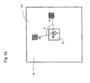
- FIG. 1a shows a schematic representation of an apparatus 10 for measuring the angle of rotation of two relative to each other about an axis of rotation D rotating objects, in particular the rotation of a shaft 16 about the axis of rotation D relative to a stationary object.
- a polarizer 14 is arranged, which in plan view in FIG. 1b is shown, and which is designed as a linear polarizer.
- the polarizer 14 is designed in particular as a disk and has a normal N, which is arranged at a first angle ⁇ to the axis of rotation D.
- the polarizer 14 is thus tilted against the axis of rotation D.
- the polarizer 14 may preferably be formed as a round disc, as in FIG. 1b shown. Alternatively, however, the geometry of the polarizer 14 may take on any shape with regard to bulges and outer contours.
- the polarizer 14 may further be arranged on the shaft 16 such that the normal N does not necessarily have an intersection with the axis of rotation D.
- the polarizer 14 is illuminated with a light source 12.
- the light source 12 has an optical axis A, which is identical to the rotation axis D in the device 10.
- the light source 12 is preferably embodied as an unpolarized light source 12, for example as an LED, but may also be designed as an incandescent lamp or as a coherent light source, for example as a laser or laser diode.
- the light source 12 preferably emits a divergent cone of light to illuminate the polarizer 14 over a large area.
- the light cone of the light source 12 is homogeneous.
- the intensity profile of the light source 12 is preferably rotationally symmetrical, for example with a Lambert or Gaussian distribution and preferably has its intensity center of gravity on the optical axis A.
- the illumination by the light source 12 may also be performed in a collimated or in parts convergent. Beam shaping of the light source 12 is not absolutely necessary. Depending on the embodiment, however, a mirror optics, a refractive or a defractive lens or a combination thereof can be used for the light source 12, the beam shaping advantageously having as little polarization as possible.
- the light source 12 is arranged on a support 18, on which a receiver is arranged.
- the plane of the light source 12 and the plane of the receiver thus coincide in this embodiment.
- the plane of the light source 12 and the plane of the receiver are offset parallel to each other.
- the light source 12 is arranged centrally on the carrier 18.
- a symmetrical design simplifies the evaluation, but is not absolutely necessary. In mutually parallel planes between light source 12 and receiver illumination by a transparent recess in the plane of the receiver or by a beam guide by means of light guides, mirrors, prisms or the like is conceivable.
- the polarizer 14 is reflective and can be designed in particular mirror-reflective, diffuse-reflective or scattering-reflective.
- the light source 12 and the receiver may preferably, in particular including required circuits for signal evaluation on a single plane, for example on the Carrier 18, built-in, resulting in an integrated and cost-effective system.
- the light of the light source 12 is linearly polarized and reflected by the polarizer so that it falls on the receiver.
- Embodiments of the transceiver unit having the light source 12 and the receiver will be described below.
- Figure 1c shows an alternative embodiment of a device 10 'for measuring the angle of rotation of the shaft 16, which differs from the in FIG. 1a only differs in that the polarizer 14 is not arranged on the end face of the shaft 16, but that the shaft 16 is passed through a preferably central recess of the polarizer 14 and the light source 12 and the receiver are arranged such that the optical Axis A of the light source 12 does not coincide with the axis of rotation D and in particular is arranged offset parallel to the axis of rotation D, so that an eccentric illumination of the polarizer 14 results.
- the shaft 16 may be formed in this embodiment as a hollow shaft.
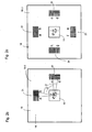
- FIG. 2a shows a first embodiment of a transceiver unit 18-1, which in the devices 10, 10 'according to the FIGS. 1a and 1c can be used.
- the transceiver unit 18-1 has a carrier 18 on which the light source 12 is preferably arranged centrally.
- the transceiver unit 18-1 further comprises two receiving elements a, c, in front of which a respective polarization filter is arranged, which have the same direction of polarization.
- the receiving elements a, c are at an angular distance at a second angle ⁇ with respect to the optical axis A, which when using the transceiver unit 18-1 in the device according to FIG. 1a with the axis of rotation D coincides, arranged.
- the angular distance is in the embodiment 90 °.
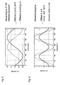
- both for the first receiving element a and the second receiving element b each result in a sinusoidal signal with a sinusoidal intensity modulation due to the wobbling motion of the polarizer 14.
- the relative intensities of the receiving elements a, c in dependence from the angle of rotation are in particular in the FIGS. 3a and 3b shown. This structure thus provides two sine square signals which provide an incremental angle signal.
- the light intensities of the receiving elements c, d provide, as a function of the rotation angle, sinusoidal-shaped signals which are modulated sinusoidally due to the tumbling motion of the polarizer 14 (cf. Fig. 3a and 3b ).
- the two receiving elements a, b provide two squares signals offset by 90 ° (cf. FIG. 3a ). The same applies to the receiving elements c, d (cf. FIG. 3b ).
- the sum of the signals of the receiving elements a, b would result in a constant function without a tumbling motion of the polarizer 14. Since due to the wobbling movement of the polarizer 14 the sinusoidal intensity modulation is superimposed on each of the two individual signals, the sum of the two receiving elements a, b, ie a + b, which is referred to as the first summation signal, yields a sinusoidal signal whose period is one full revolution by 360 ° of the polarizer 14 corresponds (see. FIG. 4a ). The same applies to the first sum signal c + d of the receiving elements c, d (cf. FIG. 4a ).
- the superimposed sinusoidal signals are phase-shifted by 90 ° (vg. FIG. 4a ).
- the absolute angular position from the sine-square signals (see FIGS. FIG. 4a ).
- Figure 2c shows a third embodiment of a transceiver unit 18-3, which differs from the embodiment according to FIG. 2b characterized in that there are two further groups 23, 24, each with two further receiving elements e, f and g, h.
- the third group 23 has the receiving elements e, f, while the fourth group 24 has the receiving elements g, h.
- the polarization directions of the receiving elements e, g correspond to the polarization direction of the receiving elements a, c.
- the polarization directions of the receiving elements f, h correspond to the polarization directions of the receiving elements b, d.
- the receiving elements a, c, e, g with the same direction of polarization are symmetrical about a center of symmetry arranged, in particular in each case at the same angular distance from one another, in particular at an angular distance of 90 °.
- two receiving elements with the same direction of polarization are arranged point-symmetrical to the center of symmetry.
- the center of symmetry lies in particular on the optical axis A and particularly preferably on the axis of rotation D.
- the third group 23 and the fourth group 24 are provided, which each have redundant signals to the reception elements a, b, c, d of the first group 21 and the second group 22 (cf. Figures 3c, 3d such as FIG. 4b ).
- the third group 23 supplies a first summation signal of e + f and the fourth group 24 a first summation signal of g + h (cf. Fig. 4b ).
- the absolute signals can also be offset compensated, as in FIG.
- first difference signals (a + b) - (e + f) or (c + d) - (g + h) are formed, which in FIG. 5 are shown and correspond to an offset-compensated absolute signal.
- the first sum signals can be added by adding the received signals the receiving elements of a group are calculated, but also as a second difference signal, the difference between two of the receiving elements of a group, in particular two receiving elements whose polarization directions are perpendicular to each other.
- the first group 21 results as a second difference signal
- the second group 22 results as a second difference signal cd
- for the third group 23 results as a second difference signal ef
- for the fourth group 24 results as a second difference signal gh.
- the second difference signals of different groups can be added to second sum signals, for example to (ab) + (cd), whereby the signal amplitude is increased and whereby, if necessary, error influences can be minimized (cf. FIG. 6 ).
- the signal stability can be further increased.
- An illumination angle deviating from 90 ° leads to a change in the polarization contrast in most polarizers. Although this only applies to larger angles, for example in the case of wire-grid polarizers at an angle of more than 20 °, in principle this effect can not be avoided.
- the rotation of the tilted polarizer results in a dynamic change in the illumination angle, which in turn leads to a superimposed sinusoidal-shaped intensity modulation on the receiving elements.
- the effect occurs only slightly or not at all in the direction of the polarizing structures of the polarizer, whereas in the 90 ° direction reaches its maximum to these structures. This means that the axis of this error will rotate with the rotation of the polarizer at the receiver level. The effect is not symmetrical at the receiver level.
- At least one group which is located on any other angular range on the receiver plane, ideally offset by 90 °, is needed.
- the signal of the second group which experiences a superimposed intensity modulation of its signal, can be corrected by forming the difference between the signals of both groups taking into account the phase offset of ideally 90 °. This provides the error signal to correct the signal of the second group.
- the prerequisite for this is the prior correction of the intensity fluctuation due to the tumbling of the polarizer and the knowledge of the coarse angular position of the structures on the polarizer, ie the absolute or optionally the incremental angle signal.
- the described correction is also possible over the difference of the respective absolute signals.
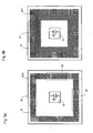
- Figure 7a shows a fourth embodiment of a transceiver unit 18-4, which has receiving elements with two different polarization directions, wherein the two polarization directions are rotated in particular by 90 ° to each other.
- the receiving elements are arranged symmetrically about a center of symmetry, which in the present case is formed by the optical axis A of the light source 12 and when using the transceiver unit 18-4 in the device 10 according to FIG. 1a in particular coincides with the axis of rotation D.
- the receiving elements are arranged in particular on a square track around the center of symmetry.
- the transmitting-receiving unit 18-4 has fourteen groups 25, each with two receiving elements, wherein in each group 25, the polarization directions of the receiving elements are each rotated by 90 ° from each other and a total of only two different polarization directions are present.
- the receiving elements of the same direction of polarization are arranged symmetrically with respect to one another, in particular at the same angular distance with respect to the center of symmetry. In particular, two receiving elements with the same direction of polarization are arranged point-symmetrically.
- FIG. 7b shows a fifth embodiment of a transceiver unit 18-5 with eight groups 25 'of receiving elements, wherein in each group 25' each two receiving elements are arranged whose polarization planes are rotated by 90 ° to each other, with a total of only two different polarization directions are present.
- the receiving elements are arranged on an annular track about a center of symmetry, wherein the center of symmetry in particular by the optical Axis A of the light source 12 and, when using the transceiver unit 18-5 in the apparatus according to FIG. 1a, is preferably formed by the axis of rotation D.
- Receiving elements with the same direction of polarization are arranged in the same angular distance from each other. In each case two receiving elements with the same direction of polarization are arranged point-symmetrical to the center of symmetry to each other.
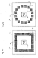
- FIG. 8a shows a sixth embodiment of a transceiver unit 18-6 with receiving elements with four different polarization directions, the polarization directions are rotated by 45 ° from each other.
- the transceiver unit 18-6 has a total of six groups 26, each with four receiving elements, wherein in each group 26, the polarization directions of the receiving elements are rotated by 45 ° from each other, so that in particular each group 26 each have a receiving element with a polarization direction of 0 ° , a receiving element with a polarization direction of 45 °, a receiving element with a polarization direction of 90 ° and a receiving element with a polarization direction of 135 °.
- the receiving elements are arranged symmetrically to a center of symmetry, which is formed in particular by the optical axis A of the light source 12 or the axis of rotation D.
- two receiving elements with the same direction of polarization are arranged point-symmetrically with respect to each other.
- FIG. 8b shows a seventh embodiment of a transceiver unit 18-7 with receiving elements with eight different polarization directions in groups 27, wherein the polarization directions are respectively rotated by 22.5 ° to each other and thus polarization directions at 0 °, 22.5 °, 45 °, 67 , 5 °, 90 °, 112.5 °, 135 °, 157.5 °.
- the reception elements are arranged on two concentrically arranged square tracks around a center of symmetry. Receiving elements with the same polarization direction are arranged point-symmetrically to the center of symmetry, in particular to the optical axis A or the axis of rotation D.
- the groups 27 do not basically have all the polarization directions, but may comprise a different number of reception elements.
- FIG. 8c shows an eighth embodiment of a transceiver unit 18-8 with receiving elements with eight different polarization directions, wherein the polarization directions are respectively rotated by 22.5 ° to each other and thus polarization directions at 0 °, 22.5 °, 45 °, 67.5 ° , 90 °, 112.5 °, 135 °, 157, 5 °.
- the receiving elements are arranged in a total of four square tracks in two nested rows symmetrically about a center of symmetry.
- the center of symmetry is in turn preferably formed by the optical axis A of the light source 12 and particularly preferably by the axis of rotation D.
- two receiving elements with the same direction of polarization are arranged point symmetrical to each other about the center of symmetry.
- the receiving elements of a group are at slightly different positions relative to the center of symmetry as a function of their geometry. This fact can be neglected if the size of the photosensitive surface of the receiving elements is comparatively small and the expected phase error is smaller than the accuracy of the device for determining the angle of rotation. However, if the photosensitive surfaces of the receiving elements could cause a significant error, computational correction can be performed with a priori knowledge of the positioning of the receiving elements at the receiver level. Alternatively, by suitable positioning of the individual groups in a redundant arrangement, a compensation of the effect can be achieved by averaging the intensity over a plurality of identical adjacent receiving elements.
- the receiving elements are shown schematically always square.
- the surface configuration of the receiving elements can be varied depending on the arrangement and manufacturing technology.
- reception elements in the form of squares, rectangles, circles, polygons, diamonds or the like are possible.
- it is advantageous for the signal evaluation if the receiving elements each have the same shape or at least the same area.
- the individual receiving elements can also have different sized areas. This is particularly useful for correction between more inward and outward receiving elements.
- the devices 10, 10 'according to the invention are particularly suitable as a so-called kit solution, in which the transceiver unit 18-1, 18-2, 18-3, 18-4, 18-5, 18-6, 18-7, 18-8 with the light source 12 and the receiver is mechanically decoupled from the polarizer 14, since it can be constructed almost free of adjustment due to the possibilities for correction or compensation of influences of mechanical tolerances.
Landscapes
- Physics & Mathematics (AREA)
- General Physics & Mathematics (AREA)
- Optical Transform (AREA)
Description
Die Erfindung betrifft eine Vorrichtung zur Messung des Drehwinkels zweier relativ zueinander um eine Drehachse rotierender Objekte gemäß dem Oberbegriff des Patentanspruchs 1.The invention relates to a device for measuring the angle of rotation of two objects rotating relative to each other about an axis of rotation according to the preamble of
Die Erfassung des Drehwinkels zweier relativ zueinander um eine Drehachse rotierender Objekte, bspw. einer sich drehenden Motorwelle relativ zu einem feststehendem Element, kann mit Hilfe eines berührungslosen optischen Sensors basierend auf den Polarisationseigenschaften des Lichts geschehen. Beispiele für derartige Vorrichtungen zeigen die
Bekannte Vorrichtungen zur Messung des Drehwinkels zweier relativ zueinander um eine Drehachse rotierender Objekte weisen eine dem einen Objekt zugeordnete Lichtquelle, einen dem anderen Objekt zugeordneten Polarisator, wobei sich die Lichtquelle und der Polarisator in Abhängigkeit vom Drehwinkel relativ zueinander drehen, und einen Empfänger auf, der die durch den Polarisator durchtretende oder reflektierte Lichtintensität misst, um ein drehwinkelabhängiges Signal zu erzeugen, wobei der Empfänger wenigstens ein erstes Empfangselement aufweist, vor welchem ein Polarisationsfilter mit einer ersten Polarisationsrichtung angeordnet ist. Je nach relativer Winkelstellung zwischen dem Polarisator und dem Polarisationsfilter des Empfangselements ergibt sich auf dem Empfangselement eine unterschiedliche Beleuchtungsintensität. Ist der Polarisator an einem sich drehenden Objekt, bspw. einer Motorwelle, angeordnet, lässt sich der Drehwinkel des sich drehenden Objekts bestimmen. Aufgrund der physikalischen Eigenschaften der Polarisation weisen die drehwinkelabhängigen Signale zwei Perioden pro Umdrehung um 360° auf und sind damit inkremental.Known devices for measuring the angle of rotation of two relative to each other rotating about a rotation axis objects have a one object associated light source, a polarizer associated with the other object, wherein the light source and the polarizer depending on the angle of rotation rotate relative to each other, and a receiver, the measures the light intensity passing through or reflected by the polarizer to produce a rotation angle dependent signal, the receiver having at least a first receiving element, in front of which a polarizing filter having a first polarization direction is arranged. Depending on the relative angular position between the polarizer and the polarizing filter of the receiving element, a different illumination intensity results on the receiving element. If the polarizer is arranged on a rotating object, for example a motor shaft, the angle of rotation of the rotating object can be determined. Due to the physical properties of the polarization, the rotation angle-dependent signals have two periods per revolution of 360 ° and are thus incremental.
Ein Problem einer Vorrichtung zur Messung des Drehwinkels zweier relativ zueinander um eine Drehachse rotierender Objekte basierend auf den Polarisationseigenschaften des Lichts besteht in der Toleranzierung der mechanischen Bewegungen, da ein Versatz in Richtung der optischen Achse oder eine nicht perfekt homogene Beleuchtung zu Intensitätsmodulationen führt, welche den gewünschten Signalen überlagert sind. Zusätzlich ergeben sich bei einem reflektierenden Polarisator zwangsläufig unterschiedliche Einfallswinkel des Lichts auf den Polarisator und den Polarisationsfilter des Empfangselements. Dies führt ebenfalls je nach geometrischer Konstellation und Art der Polarisation zu einer Variation der Intensität in den Empfangselementen.A problem of a device for measuring the angle of rotation of two objects rotating relative to one another based on the polarization properties of the light is the tolerance of the mechanical movements, since an offset in the direction of the optical axis or a not perfectly homogeneous illumination leads to intensity modulations which cause the superimposed on desired signals. In addition, different angles of incidence of the light on the polarizer and the polarization filter of the receiving element inevitably result in the case of a reflective polarizer. This also leads depending on the geometric constellation and type of polarization to a variation of the intensity in the receiving elements.
Die Aufgabe der Erfindung besteht darin, eine Eindeutigkeit über eine volle Umdrehung um 360° des rotierenden Objekts und somit ein absolutes Winkelsignal zu ermöglichen, wobei vorzugsweise gleichzeitig ein absolutes und ein inkrementales Signal ermittelt werden soll, ohne Einbußen bei der Signalqualität zu verursachen.The object of the invention is to allow a uniqueness over a full revolution through 360 ° of the rotating object and thus an absolute angle signal, preferably at the same time an absolute and an incremental signal to be determined without causing loss of signal quality.
Die Aufgabe der Erfindung wird gelöst durch eine Vorrichtung zur Messung des Drehwinkels zweier relativ zueinander um eine Drehachse rotierender Objekte mit den Merkmalen des Patentanspruchs 1 sowie ein Verfahren zur Messung des Drehwinkels zweier relativ zueinander um eine Drehachse rotierender Objekte mit den Merkmalen des Patentanspruchs 13.The object of the invention is achieved by a device for measuring the angle of rotation of two objects rotating relative to each other about an axis of rotation with the features of
Vorteilhafte Ausgestaltungen und Weiterbildungen der Erfindung sind in den abhängigen Ansprüchen angegeben.Advantageous embodiments and further developments of the invention are specified in the dependent claims.
Die erfindungsgemäße Vorrichtung zur Messung des Drehwinkels zweier relativ zueinander um eine Drehachse rotierender Objekte, mit einer dem einen Objekt zugeordneten Lichtquelle, mit einem dem anderen Objekt zugeordneten Polarisator, wobei sich die Lichtquelle und der Polarisator in Abhängigkeit vom Drehwinkel relativ zueinander drehen, und mit einem Empfänger, der die durch den Polarisator durchtretende oder reflektierte Lichtintensität misst, um ein drehwinkelabhängiges Signal zu erzeugen, wobei der Empfänger wenigstens ein erstes Empfangselement aufweist, vor welchem ein Polarisationfilter mit einer ersten Polarisationsrichtung angeordnet ist, zeichnet sich dadurch aus, dass der Polarisator als Scheibe mit einer Normalen ausgebildet ist, wobei die Normale der Scheibe in einem ersten von 0° verschiedenen Winkel zu der Drehachse angeordnet ist, und dass der Empfänger wenigstens ein zweites Empfangselement aufweist, vor welchem ein Polarisationsfilter angeordnet ist, welcher vorzugsweise die erste Polarisationsrichtung aufweist, wobei das zweite Empfangselement in einem Winkelabstand mit einem zweiten Winkel bezüglich eines Symmetriezentrums, welches insbesondere durch die optische Achse der Lichtquelle oder die Drehachse des rotierenden Objekts bestimmt wird, zu dem ersten Empfangselement angeordnet ist. Dadurch, dass der Polarisator mit seiner Normalen in einem von 0° verschiedenen Winkels zu der Drehachse angeordnet ist, ergibt sich bei Drehung des Polarisators um die Drehachse eine Taumelbewegung, welche eine sinusförmige Intensitätsmodulation auf jedem der Empfangselemente hervorruft, welche bei einer Umdrehung um 360° genau eine Periode aufweist. Diese Taumelbewegung verursacht somit eine Brechung der Symmetrie, die gezielt zur Generierung einer eindeutigen Winkelinformation über 360° genutzt wird. Zusätzlich weist der Empfänger ein zweites Empfangselement in einem Winkelabstand zu dem ersten Empfangselement auf, so dass zwischen den beiden Lichtintensitätssignalen der beiden Empfangselemente eine unterschiedliche Phasenlage erzeugt wird, welche eine eindeutige Winkelinformation über 360° auch bei jedem Nulldurchgang ermöglichen.The device according to the invention for measuring the angle of rotation of two objects rotating relative to each other about a rotation axis, with a light source associated with the one object, with a polarizer associated with the other object, wherein the light source and the polarizer rotate relative to one another in dependence on the angle of rotation, and with a A receiver measuring the light intensity passing through or reflected by the polarizer to produce a rotation angle dependent signal, the receiver having at least a first receiving element, in front of which a polarization filter having a first polarization direction is arranged, is characterized in that the polarizer is a disk is formed with a normal, wherein the normal of the disc is arranged at a first angle different from 0 ° to the axis of rotation, and that the receiver comprises at least a second receiving element, in front of which a polarizing filter is arranged, which v Preferably, the first polarization direction has the second receiving element arranged at an angular distance at a second angle relative to a center of symmetry, which is determined in particular by the optical axis of the light source or the axis of rotation of the rotating object, to the first receiving element. Characterized in that the polarizer is arranged with its normal in a different angle from the 0 ° to the axis of rotation, results in a rotation of the polarizer about the axis of rotation a wobbling motion, which causes a sinusoidal intensity modulation on each of the receiving elements, which in one revolution by 360 ° has exactly one period. This wobbling motion thus causes a break in the symmetry, which is specifically used to generate a clear angle information over 360 ° becomes. In addition, the receiver has a second receiving element at an angular distance from the first receiving element, so that between the two light intensity signals of the two receiving elements, a different phase position is generated, which allow a clear angle information over 360 ° even at each zero crossing.
Vorzugsweise ist der erste Winkel größer als 0° und kleiner als 45°, liegt vorzugsweise zwischen 3° und 20° und beträgt besonders bevorzugt etwa 5°. Ein derartiger Winkel führt bereits zu einer signifikanten Intensitätsmodulation der Lichtintensitäten der unterschiedlichen Empfangselemente, die eine eindeutige Winkelinformation über 360° ermöglicht.Preferably, the first angle is greater than 0 ° and less than 45 °, preferably between 3 ° and 20 °, and more preferably about 5 °. Such an angle already leads to a significant intensity modulation of the light intensities of the different receiving elements, which allows unambiguous angle information over 360 °.
Gemäß einer bevorzugten Ausführungsform beträgt der zweite Winkel 90°, so dass auch die Phasendifferenz der Lichtintensitätssignale des ersten Empfangselements und des zweiten Empfangselements 90° beträgt, was eine vereinfachte Auswertung der detektierten Signale ermöglicht.According to a preferred embodiment, the second angle is 90 °, so that the phase difference of the light intensity signals of the first receiving element and the second receiving element is 90 °, which allows a simplified evaluation of the detected signals.
Vorzugsweise weist die Lichtquelle eine optische Achse auf, welche mit der Drehachse übereinstimmt, was einen kompakten Aufbau der Vorrichtung ermöglicht.Preferably, the light source has an optical axis which coincides with the axis of rotation, allowing a compact construction of the device.
Gemäß einer bevorzugten Ausführungsform der Erfindung ist die Lichtquelle in einer ersten Ebene angeordnet und der Empfänger in einer zweiten Ebene angeordnet, wobei die erste Ebene entweder der zweiten Ebene entspricht oder parallel versetzt zu dieser angeordnet ist. Eine derartige Anordnung ermöglicht ebenfalls einen kompakten Aufbau der Vorrichtung.According to a preferred embodiment of the invention, the light source is arranged in a first plane and the receiver is arranged in a second plane, wherein the first plane either corresponds to the second plane or is arranged offset parallel thereto. Such an arrangement also allows a compact construction of the device.
Vorzugsweise weist die Lichtquelle ein divergentes Strahlprofil und/oder ein rotationssymmetrisches Strahlprofil auf, um eine gute Ausleuchtung aller Empfangselemente zu ermöglichen.Preferably, the light source has a divergent beam profile and / or a rotationally symmetric beam profile in order to enable a good illumination of all the reception elements.
Gemäß einer besonders bevorzugten Ausführungsform der Erfindung ist das erste Empfangselement Teil einer ersten Gruppe von n Empfangselementen, wobei vor jeden der n Empfangselemente ein Polarisationselement angeordnet ist und die Polarisationsrichtungen der Polarisationselemente gegeneinander verdreht sind, vorzugsweise jeweils um 180°/n, wobei n die Anzahl der Empfangselemente der ersten Gruppe ist, und das zweite Empfangselement Teil einer zweiten Gruppe von m Empfangselementen ist, wobei vor jedem der m Empfangselemente ein Polarisationselement angeordnet ist und die Polarisationsrichtungen der Polarisationselemente gegeneinander verdreht, vorzugsweise jeweils um 180°/m, wobei m die Anzahl der Empfangselemente der zweiten Gruppe ist, wobei vorzugsweise Empfangselemente mit gleichen Polarisationsrichtungen jeweils den gleichen Winkelabstand zueinander aufweisen. n und/oder m kann bspw. 2 oder eine Potenz von 2 betragen. Bei Verwendung von zwei Gruppen mit jeweils zwei Empfangselementen, deren Polarisationsrichtungen jeweils um 90° verdreht sind, und wobei die Gruppen im Winkelabstand von 90° angeordnet sind, ergibt sich die Möglichkeit der Bestimmung des absoluten Drehwinkels auch bei Verwendung von idealen Polarisatoren.According to a particularly preferred embodiment of the invention, the first receiving element is part of a first group of n receiving elements, wherein before each of the n receiving elements, a polarizing element is arranged and the polarization directions of the polarizing elements are rotated against each other, preferably each by 180 ° / n, where n is the number is the receiving elements of the first group, and the second receiving element is part of a second group of m receiving elements, wherein before each of the m receiving elements, a polarizing element is arranged and the polarization directions of the polarization elements rotated against each other, preferably each 180 ° / m, where m is the number the receiving elements of the second group, wherein preferably receiving elements having the same polarization directions each have the same angular distance from one another. n and / or m can be, for example, 2 or a power of 2. When using two groups each with two receiving elements whose polarization directions are each rotated by 90 °, and wherein the groups are arranged at an angular distance of 90 °, there is the possibility of determining the absolute rotation angle, even when using ideal polarizers.
Vorzugsweise weist der Empfänger wenigstens vier oder mehr Gruppen von Empfangselementen auf, wobei die Gruppen vorzugsweise gleich viele Empfangselemente aufweist und vorzugsweise symmetrisch, insbesondere um die Drehachse oder die optische Achse, angeordnet sind. Bei Verwendung von genau vier Gruppen mit jeweils zwei Empfangselementen ergibt sich bereits die Möglichkeit einer für die Signalauswertung vorteilhaften Offsetkompensation.Preferably, the receiver has at least four or more groups of receiving elements, wherein the groups preferably have the same number of receiving elements and are preferably arranged symmetrically, in particular about the axis of rotation or the optical axis. When using exactly four groups, each with two receiving elements already results in the Possibility of an advantageous for the signal evaluation offset compensation.
Durch den Einsatz mehrerer Gruppen mit mehreren Empfangselementen lässt sich die Genauigkeit der Vorrichtung sowohl hinsichtlich der inkrementalen als auch der absoluten Signale steigern. Es kann hierfür die Anzahl identischer Gruppen und/oder die Anzahl von Empfangselementen mit unterschiedlich detektierbarer Polarisationsrichtung erhöht werden, so dass sich vielfache Möglichkeiten für Differenzauswertungen z.B. zur Offsetkompensation oder zur Minimierung von Einflüssen lokaler optischer Störungen wie bspw. von lokalem Streulicht oder Schmutz auf dem Polarisator oder vielfache Möglichkeiten für Redundanzen beispielsweise durch Addition zweier oder mehrerer gleichartiger Signale ergeben.By using multiple groups with multiple receiving elements, the accuracy of the device can be increased both in terms of incremental and absolute signals. For this purpose, the number of identical groups and / or the number of receiving elements with different detectable polarization direction can be increased, so that multiple possibilities for differential evaluations, e.g. for offset compensation or to minimize the influence of local optical disturbances such as localized light or dirt on the polarizer or multiple opportunities for redundancy, for example, by adding two or more similar signals.
Vorzugsweise sind jeweils zwei Empfangselemente mit gleicher Polarisationsrichtung punktsymmetrisch, vorzugsweise zu der Drehachse oder der optischen Achse, angeordnet. Symmetrische Anordnungen erleichtern die entsprechend Signalauswertung.Preferably, in each case two receiving elements with the same polarization direction are arranged point-symmetrically, preferably with respect to the axis of rotation or the optical axis. Symmetrical arrangements facilitate the corresponding signal evaluation.
Gemäß einer bevorzugten Ausführungsform sind die Empfangselemente auf wenigstens einer, vorzugsweise auf zwei oder mehreren, rechteckigen, vorzugsweise quadratischen, oder kreisförmigen Spuren, vorzugsweise um die Drehachse oder die optische Achse, angeordnet. Auch dies führt insbesondere zu einem symmetrischen Aufbau und erleichtert die Signalauswertung.According to a preferred embodiment, the receiving elements are arranged on at least one, preferably on two or more, rectangular, preferably square, or circular tracks, preferably around the axis of rotation or the optical axis. This also leads in particular to a symmetrical structure and facilitates the signal evaluation.
Vorzugsweise weist der Empfänger eine oder mehrere Referenzphotodioden auf, um weitere Korrekturen oder Kompensationsmöglichkeiten, insbesondere bei lokalen oder globalen Intensitätsschwankungen, bereit zu stellen. Die Referenzphotodioden sind lediglich optional und können in Abhängigkeit von der Anordnung der Empfangselemente mit davor angeordneten Polarisationselementen in ggf. vorhandenen freien Flächen angeordnet werden.The receiver preferably has one or more reference photodiodes in order to provide further corrections or compensation possibilities, in particular in the case of local or global intensity fluctuations. The reference photodiodes are merely optional and may vary depending on the arrangement the receiving elements are arranged with previously arranged polarization elements in any existing free areas.
Gemäß einer bevorzugten Ausführungsform der Erfindung sind die Lichtquelle, der Empfänger und eine Auswerteschaltung als integrierte Schaltung ausgebildet, was zu einem hochintegrierten und kostengünstigen System führt.According to a preferred embodiment of the invention, the light source, the receiver and an evaluation circuit are formed as an integrated circuit, resulting in a highly integrated and cost-effective system.
Das erfindungsgemäße Verfahren zur Messung des Drehwinkels zweier relativ zueinander um eine Drehachse rotierende Objekte mit einer Vorrichtung gemäß einem der vorhergehenden Ansprüche, wobei die vom Empfänger gemessene Lichtintensität als drehwinkelabhängiges Signal ausgewertet wird, zeichnet sich dadurch aus, dass die von den einzelnen Empfangselementen gemessenen Lichtintensitäten als drehwinkelabhängige Signale ausgewertet werden. Dadurch ergibt sich auf einfache Art und Weise die Möglichkeit, den Drehwinkel über eine volle Drehung von 360° absolut zu bestimmen und gleichzeitig ein absolutes und inkrementales Signal zu generieren, ohne Einbußen bei der Signalqualität zu verursachen.The method according to the invention for measuring the angle of rotation of two objects rotating relative to one another about a rotation axis with a device according to one of the preceding claims, wherein the light intensity measured by the receiver is evaluated as a rotation angle-dependent signal is characterized in that the light intensities measured by the individual reception elements angle-dependent signals are evaluated. This provides a simple way to determine the rotation angle over a full rotation of 360 ° absolute and at the same time to generate an absolute and incremental signal, without causing loss of signal quality.
Gemäß einer bevorzugten Ausführungsform des erfindungsgemäßen Verfahrens werden die Empfangssignale der Empfangselemente einer Gruppe zu einem ersten Summensignal summiert. Das erste Summensignal ergäbe ohne ein Taumeln des Polarisators idealerweise einen konstanten Wert. Die erfindungsgemäß eingeführte Taumelbewegung des Polarisators führt dazu, dass die Summe der Empfangssignale der Empfangselemente einer Gruppe direkt ein sinusförmiges Signal liefert, dessen Periode einer Umdrehung des Polarisators entspricht. Somit wird auf diese Weise insbesondere ein Absolutsignal erzeugt.According to a preferred embodiment of the method according to the invention, the received signals of the receiving elements of a group are summed to form a first summation signal. The first summation signal would ideally give a constant value without wobbling of the polarizer. The inventively introduced tumbling motion of the polarizer causes the sum of the received signals of the receiving elements of a group directly delivers a sinusoidal signal whose period corresponds to one revolution of the polarizer. Thus, in particular an absolute signal is generated in this way.
Vorzugsweise wird aus den ersten Summensignalen zweier verschiedener Gruppen, insbesondere punktsymmetrisch zur Drehachse zueinander angeordneter Gruppen, ein erstes Differenzsignal gebildet, um die Absolutsignale offsetkompensiert bestimmen zu können.Preferably, a first difference signal is formed from the first sum signals of two different groups, in particular point-symmetrical to the rotation axis of mutually arranged groups, in order to be able to determine the absolute signals offset-compensated.
Vorzugsweise wird aus den Empfangssignalen zweier der Empfangselemente einer Gruppe, insbesondere zweier Empfangselemente, deren Polarisationsrichtungen senkrecht zueinander stehen, ein zweites Differenzsignal gebildet, welches eine Ermittlung der inkrementalen Winkelpositionen basierend auf einem korrigierten Sinusquadratsignal ermöglicht.Preferably, a second difference signal is formed from the received signals of two of the receiving elements of a group, in particular two receiving elements whose polarization directions are perpendicular to each other, which enables a determination of the incremental angular positions based on a corrected sine square signal.
Vorzugsweise wird aus zwei zweiten Differenzsignalen zweier verschiedener Gruppen, insbesondere punktsymmetrisch zur Drehachse zueinander angeordneter Gruppen, ein zweites Summensignal gebildet, um die Signalamplitude zu erhöhen und lokale Fehlereinflüsse zu minimieren.Preferably, a second sum signal is formed from two second difference signals of two different groups, in particular point-symmetrically to the axis of rotation of mutually arranged groups, in order to increase the signal amplitude and to minimize local error influences.
Durch mehrfach kaskadierte Berechnung von Differenzsignalen oder Summensignalen lässt sich die Signalstabilität, insbesondere bei Verwendung von mehreren Gruppen mit mehreren Empfangselementen, weiter steigern.By multiple cascaded calculation of difference signals or sum signals, the signal stability, especially when using multiple groups with multiple receiving elements, further increase.
Vorzugsweise werden die Empfangssignale der Empfangselemente, welche gleiche Polarisationsrichtungen aufweisen, gemittelt, um die Genauigkeit der Winkelbestimmung weiter zu erhöhen.Preferably, the received signals of the receiving elements, which have the same polarization directions, are averaged in order to further increase the accuracy of the angle determination.
Die Erfindung wird anhand der nachfolgenden Figuren ausführlich erläutert. Es zeigt
- Figur 1a
- eine schematische Darstellung einer Vorrichtung zu Messung des Drehwinkels zweier relativ zueinander um eine Drehachse rotierender Objekte gemäß einem ersten Ausführungsbeispiel der Erfindung,
- Figur 1b
- eine Draufsicht auf den Polarisator der Vorrichtung gemäß
Fig. 1a , - Figur 1c
- eine schematische Darstellung einer Vorrichtung zur Messung des Drehwinkels zweier relativ zueinander um eine Drehachse rotierender Objekte gemäß einem zweiten Ausführungsbeispiel der Erfindung,
- Figur 2a
- eine schematische Darstellung eines Empfängers für eine Vorrichtung gemäß
Fig. 1a oder1c gemäß einem ersten Ausführungsbeispiel, - Figur 2b
- ein zweites Ausführungsbeispiel eines Empfängers für die Vorrichtung gemäß
Fig. 1a oder1c , - Figur 2c
- ein drittes Ausführungsbeispiel eines Empfängers für eine Vorrichtung gemäß
Fig. 1a oder1c , - Figur 3a
- die relativen Intensitäten zweier der Empfangselemente des Empfängers gemäß
Fig. 2b oder 2c in Abhängigkeit vom Drehwinkel, - Figur 3b
- die relativen Intensitäten zweier der Empfangselemente des Empfängers gemäß
Fig. 2b oder 2c in Abhängigkeit vom Drehwinkel, - Figur 3c
- die relativen Intensitäten zweier der Empfangselemente des Empfängers gemäß
Fig. 2c in Abhängigkeit vom Drehwinkel, - Figur 3d
- die relativen Intensitäten zweier der Empfangselemente des Empfängers gemäß
Fig. 2c in Abhängigkeit vom Drehwinkel, - Figur 4a
- relative Intensitäten von Summensignalen von Empfangselementen des Empfängers gemäß
Fig. 2c in Abhängigkeit vom Drehwinkel, - Figur 4b
- relative Intensitäten von Summensignalen von Empfangselementen des Empfängers gemäß
Fig. 2c in Abhängigkeit vom Drehwinkel, - Figur 5
- relative Intensitäten von Differenzsignalen von Summensignalen von Empfangselementen des Empfängers gemäß
Fig. 2c in Abhängigkeit vom Drehwinkel, - Figur 6
- relative Intensitäten in Abhängikeit vom Drehwinkel von Inkrementalsignalen,
- Figur 7a
- ein viertes Ausführungsbeispiel von Differenzsignalen von Empfangselementen des Empfängers gemäß
Fig. 2c und eines Summensignals zweier Differenzsignale von Empfangselementen eines Empfängers gemäßFig. 2c in Abhängigkeit vom Drehwinkel, - Figur 7b
- ein fünftes Ausführungsbeispiel eines Empfängers für eine Vorrichtung gemäß
Fig. 1a oder1c , - Figur 8a
- ein sechstes Ausführungsbeispiel eines Empfängers für eine Vorrichtung gemäß
Fig. 1a oder1c , - Figur 8b
- ein siebtes Ausführungsbeispiel eines Empfängers für eine Vorrichtung gemäß
Fig. 1a oder1c und - Figur 8c
- ein achtes Ausführungsbeispiel eines Empfängers für eine Vorrichtung gemäß
Fig. 1a oder1c .
- FIG. 1a
- a schematic representation of an apparatus for measuring the angle of rotation of two relative to each other about an axis of rotation of rotating objects according to a first embodiment of the invention,
- FIG. 1b
- a plan view of the polarizer of the device according to
Fig. 1a . - Figure 1c
- 1 is a schematic representation of an apparatus for measuring the angle of rotation of two objects rotating relative to each other about a rotation axis according to a second embodiment of the invention,
- FIG. 2a
- a schematic representation of a receiver for a device according to
Fig. 1a or1c according to a first embodiment, - FIG. 2b
- A second embodiment of a receiver for the device according to
Fig. 1a or1c . - Figure 2c
- A third embodiment of a receiver for a device according to
Fig. 1a or1c . - FIG. 3a
- the relative intensities of two of the receiving elements of the receiver according to
Fig. 2b or 2c depending on the angle of rotation, - FIG. 3b
- the relative intensities of two of the receiving elements of the receiver according to
Fig. 2b or 2c depending on the angle of rotation, - Figure 3c
- the relative intensities of two of the receiving elements of the receiver according to
Fig. 2c depending on the angle of rotation, - 3d figure
- the relative intensities of two of the receiving elements of the receiver according to
Fig. 2c depending on the angle of rotation, - FIG. 4a
- relative intensities of sum signals of receiving elements of the receiver according to
Fig. 2c depending on the angle of rotation, - FIG. 4b
- relative intensities of sum signals of receiving elements of the receiver according to
Fig. 2c depending on the angle of rotation, - FIG. 5
- relative intensities of difference signals of sum signals of receiving elements of the receiver according to
Fig. 2c depending on the angle of rotation, - FIG. 6
- relative intensities as a function of the angle of rotation of incremental signals,
- Figure 7a
- A fourth embodiment of differential signals of receiving elements of the receiver according to
Fig. 2c and a sum signal of two difference signals from receiving elements of a receiver according toFig. 2c depending on the angle of rotation, - FIG. 7b
- A fifth embodiment of a receiver for a device according to
Fig. 1a or1c . - FIG. 8a
- A sixth embodiment of a receiver for a device according to
Fig. 1a or1c . - FIG. 8b
- A seventh embodiment of a receiver for a device according to
Fig. 1a or1c and - FIG. 8c
- an eighth embodiment of a receiver for a device according to
Fig. 1a or1c ,
Der Polarisator 14 wird mit einer Lichtquelle 12 beleuchtet. Die Lichtquelle 12 weist eine optische Achse A auf, welche bei der Vorrichtung 10 mit der Drehachse D identisch ist. Die Lichtquelle 12 ist vorzugsweise als unpolarisierte Lichtquelle 12, bspw. als LED, ausgebildet, kann jedoch auch als eine Glühlampe oder als kohärente Lichtquelle, bspw. als Laser oder Laserdiode, ausgebildet sein. Die Lichtquelle 12 sendet vorzugsweise einen divergenten Lichtkegel aus, um den Polarisator 14 großflächig zu beleuchten. Vorzugsweise ist der Lichtkegel der Lichtquelle 12 homogen. Das Intensitätsprofil der Lichtquelle 12 ist vorzugsweise rotationssymmetrisch, bspw. mit einer Lambert- oder Gaußverteilung und hat vorzugsweise ihren Intensitätsschwerpunkt auf der optischen Achse A. Die Beleuchtung durch die Lichtquelle 12 kann auch kollimiert oder in Teilen konvergent ausgeführt sein. Eine Strahlformung der Lichtquelle 12 ist nicht zwingend notwendig. Je nach Ausführungsform kann jedoch für die Lichtquelle 12 eine Spiegeloptik, eine refraktive oder defraktive Linse oder eine Kombination daraus verwendet werden, wobei vorteilhafterweise die Strahlformung möglichst wenig polarisierend wirkt.The
Bei der in
Der Polarisator 14 ist reflektierend ausgebildet und kann insbesondere spiegel-reflektierend, diffus-reflektierend oder streuend-reflektierend ausgelegt sein.The
Die Lichtquelle 12 und der Empfänger können vorzugsweise insbesondere einschließlich benötigter Schaltkreise zur Signalauswertung auf einer einzigen Ebene, beispielsweise auf dem Träger 18, integriert aufgebaut werden, was zu einem integrierten und kostengünstigen System führt.The
Das Licht der Lichtquelle 12 wird durch den Polarisator linear polarisiert und reflektiert, so dass es auf den Empfänger fällt. Ausführungsbeispiele der Sende-Empfangseinheit, welche die Lichtquelle 12 und den Empfänger aufweist, werden nachfolgend beschrieben.The light of the
Bei Drehung der Welle 16 und somit des Polarisators 14 ergeben sich sowohl für das erste Empfangselement a als auch das zweite Empfangselement b jeweils ein Sinusquadrat-Signal mit einer sinusförmigen Intensitätsmodulation aufgrund der Taumelbewegung des Polarisators 14. Die relativen Intensitäten der Empfangselemente a, c in Abhängigkeit vom Drehwinkel sind insbesondere in den
Die beiden Empfangselemente a, b liefern zwei um 90° versetzte Sinusquadratsignale (vgl.
Die Summe der Signale der Empfangselemente a, b ergäbe ohne eine Taumelbewegung des Polarisators 14 eine konstante Funktion. Da aufgrund der Taumelbewegung des Polarisators 14 den beiden Einzelsignalen jeweils eine sinusförmige Intensitätsmodulation überlagert wird, liefert die Summe der beiden Empfangselemente a, b, d. h. a+b, welches als erstes Summensignal bezeichnet wird, ein sinusförmiges Signal, dessen Periode einer vollen Umdrehung um 360° des Polarisators 14 entspricht (vgl.
Da davon ausgegangen wird, dass ein Signaloffset durch einen Gleichlichtanteil der Beleuchtung, beispielsweise auch durch Streulicht oder ähnliches, die Auswertung der Absolutsignale beeinträchtigt, sind die dritte Gruppe 23 und die vierte Gruppe 24 vorgesehen, welche jeweils redundante Signale zu den Empfangselementen a, b, c, d der ersten Gruppe 21 und der zweiten Gruppe 22 liefern (vgl.
Innerhalb einer Gruppe von Empfangselementen können nicht nur die ersten Summensignale durch Addition der Empfangssignale der Empfangselemente einer Gruppe berechnet werden, sondern ebenfalls als zweites Differenzsignal die Differenz zweier der Empfangselemente einer Gruppe, insbesondere zweier Empfangselemente, deren Polarisationsrichtungen senkrecht zueinander stehen. Für die erste Gruppe 21 ergibt sich als zweites Differenzsignal a-b, für die zweite Gruppe 22 ergibt sich als zweites Differenzsignal c-d, für die dritte Gruppe 23 ergibt sich als zweites Differenzsignal e-f und für die vierte Gruppe 24 ergibt sich als zweites Differenzsignal g-h. Dies führt zu einem korrigierten Sinusquadratsignal und somit zu einem korrigierten Inkrementalsignal, welches beispielsweise in
Durch mehrfache kaskadierte Berechnung von Differenzsignalen oder Summensignalen, je nach Anzahl zur Verfügung stehender Detektoren, lässt sich die Signalstabilität weiter steigern.By multiple cascaded calculation of differential signals or sum signals, depending on the number of available detectors, the signal stability can be further increased.
Ein von 90° abweichender Beleuchtungswinkel führt bei den meisten Polarisatoren zu einer Veränderung des Polarisationskontrasts. Zwar gilt dies nur für größere Winkel, beispielsweise bei Wire-Grid-Polarosatoren bei einem Winkel von mehr als 20°, prinzipbedingt lässt sich dieser Effekt allerdings nicht vermeiden. Die Drehung des verkippten Polarisators führt zu einer dynamischen Änderung des Beleuchtungswinkels, was wiederum zu einer überlagerten sinusquadrat-förmigen Intensitätsmodulation auf den Empfangselementen führt. Der Effekt tritt in Richtung der polarisierenden Strukturen des Polarisators nur gering bis gar nicht auf, wohingegen er in 90°-Richtung zu diesen Strukturen sein Maximum erreicht. Dies bedeutet, dass sich die Achse dieses Fehlers mit der Drehung des Polarisators auf der Empfängerebene mit dreht. Der Effekt ist auf der Empfängerebene nicht symmetrisch.An illumination angle deviating from 90 ° leads to a change in the polarization contrast in most polarizers. Although this only applies to larger angles, for example in the case of wire-grid polarizers at an angle of more than 20 °, in principle this effect can not be avoided. The rotation of the tilted polarizer results in a dynamic change in the illumination angle, which in turn leads to a superimposed sinusoidal-shaped intensity modulation on the receiving elements. The effect occurs only slightly or not at all in the direction of the polarizing structures of the polarizer, whereas in the 90 ° direction reaches its maximum to these structures. This means that the axis of this error will rotate with the rotation of the polarizer at the receiver level. The effect is not symmetrical at the receiver level.
Zur Kompensation dieses Fehlers können Fehlersignale, also insbesondere erste Summensignale, aus zwei verschiedenen Gruppen generiert werden. Eine der beiden Gruppen muss sich auf der Achse in Richtung der Struktur der polarisierenden Elemente auf dem Polarisator befinden. Da hier der Fehler praktisch nicht auftritt, liefert diese Gruppe das offsetkorrigierte Referenzsignal. Für die Generierung eines Inkrementalsignals würde die Auswertung dieser Gruppe bereits genügen, so dass die Signale vom Effekt betroffener Gruppen ignoriert werden könnten.To compensate for this error, error signals, in particular first sum signals, can be generated from two different groups. One of the two groups must be located on the axis in the direction of the structure of the polarizing elements on the polarizer. Since the error practically does not occur here, this group supplies the offset-corrected reference signal. For the generation of an incremental signal, the evaluation of this group would already be sufficient, so that the signals could be ignored by the effect of affected groups.
Zur Generierung eines Absolutsignals wird jedoch mindestens eine Gruppe, die sich auf einem beliebigen anderen Winkelbereich auf der Empfängerebene befindet, idealerweise um 90° versetzt dazu, benötigt.To generate an absolute signal, however, at least one group, which is located on any other angular range on the receiver plane, ideally offset by 90 °, is needed.
Das Signal der zweiten Gruppe, das eine überlagerte Intensitätsmodulation seines Signals erfährt, kann korrigiert werden, indem die Differenz aus den Signalen beider Gruppen unter Berücksichtigung des Phasenversatzes von idealerweise 90° gebildet wird. Diese liefert das Fehlersignal zur Korrektur des Signals der zweiten Gruppe. Voraussetzung hierfür ist die vorherige Korrektur der Intensitätsschwankung durch das Taumeln des Polarisators sowie die Kenntnis der groben Winkelposition der Strukturen auf dem Polarisator, d. h. des absoluten öder wahlweise des inkrementalen Winkelsignals.The signal of the second group, which experiences a superimposed intensity modulation of its signal, can be corrected by forming the difference between the signals of both groups taking into account the phase offset of ideally 90 °. This provides the error signal to correct the signal of the second group. The prerequisite for this is the prior correction of the intensity fluctuation due to the tumbling of the polarizer and the knowledge of the coarse angular position of the structures on the polarizer, ie the absolute or optionally the incremental angle signal.
Alternativ ist die beschriebene Korrektur auch über die Differenz der jeweiligen Absolutsignale möglich.Alternatively, the described correction is also possible over the difference of the respective absolute signals.
Insgesamt lassen sich vorteilhafterweise für die Positionierung der einzelnen Empfangselemente bei Gruppen mit wenigstens zwei Empfangselementen einige einfache Regeln aufstellen:
- Es sollten immer wenigstens zwei unmittelbar benachbarte Empfangselemente mit identischer photoempfindlicher Fläche und vorzugsweise 90° Phasenversatz der detektierbaren linearen Polarisation eine Gruppe bilden. Die genaue Lage oder Symmetrie der beiden ist zunächst unerheblich. Die Gruppe kann weitere Empfangselemente mit weiteren Polarisationsrichtungen aufweise. Diese Gruppe sollte sich mindestens ein weiteres Mal, vorzugsweise um 90° zur ersten Gruppe versetzt bezüglich des Symmetriezentrums, vorhanden sein. Um eine Offsetkompensation der Absolutsignale zu ermöglichen, sollte diese Gruppe insgesamt wenigstens vier Mal vorhanden sein, vorzugsweise im Winkelabstand von jeweils 90°. Idealerweise befinden sich jeweils identische Empfangselemente auf einer Geraden durch das Symmetriezentrum im gleichen Abstand zu dem Symmetriezentrum und somit punktsymmetrisch zueinander auf dem Träger. Die Empfangselemente sollten vorzugsweise jeweils gleiche photoempfindliche Fläche aufweisen.
- It should always at least two immediately adjacent receiving elements with identical photosensitive surface and preferably 90 ° phase shift of the detectable linear polarization form a group. The exact position or symmetry of the two is initially irrelevant. The group can have further receiving elements with further polarization directions. This group should be present at least one more time, preferably offset by 90 ° to the first group with respect to the center of symmetry. In order to enable offset compensation of the absolute signals, this group should be present at least four times in total, preferably at an angular distance of 90 ° in each case. Ideally, each identical receiving elements are located on a straight line through the center of symmetry at the same distance to the center of symmetry and thus point-symmetrical to each other on the carrier. The receiving elements should preferably each have the same photosensitive surface.
Bei der Auswertung der Signalintensitäten ist vorzugsweise darauf zu achten, dass sich die Empfangselemente einer Gruppe in Abhängigkeit ihrer Geometrie an geringfügig unterschiedlichen Positionen bezüglich der Symmetriezentrums befinden. Dieser Umstand kann vernachlässigt werden, wenn die Größe der photoempfindlichen Fläche der Empfangselemente vergleichsweise klein ist und der zu erwartende Phasenfehler kleiner ist als die Genauigkeit der Vorrichtung zur Bestimmung des Drehwinkels. Falls die photoempfindlichen Flächen der Empfangselemente jedoch einen signifikanten Fehler hervorrufen könnten, kann eine rechnerische Korrektur mit A Priori Wissen um die Positionierung der Empfangselemente auf der Empfängerebene durchgeführt werden. Alternativ kann durch geeignete Positionierung der einzelnen Gruppen in einer redundanten Anordnung eine Kompensation des Effekts erreicht werden, indem die Intensität über mehrere identische benachbarte Empfangselemente gemittelt wird. Auch für die Helligkeitsverteilung in radialer Richtung kann es notwendig sein, eine Korrektur zwischen weiter innen und weiter außen liegenden Empfangselementen einzuführen oder dies ebenso durch Mittelung der Intensität mehrerer Empfangselemente oder Gruppen von Empfangselementen in unterschiedlicher Entfernung zum Symmetriezentrum zu kompensieren.When evaluating the signal intensities, it is preferable to ensure that the receiving elements of a group are at slightly different positions relative to the center of symmetry as a function of their geometry. This fact can be neglected if the size of the photosensitive surface of the receiving elements is comparatively small and the expected phase error is smaller than the accuracy of the device for determining the angle of rotation. However, if the photosensitive surfaces of the receiving elements could cause a significant error, computational correction can be performed with a priori knowledge of the positioning of the receiving elements at the receiver level. Alternatively, by suitable positioning of the individual groups in a redundant arrangement, a compensation of the effect can be achieved by averaging the intensity over a plurality of identical adjacent receiving elements. Also for the brightness distribution in the radial direction, it may be necessary to introduce a correction between receiving elements located farther inwards and farther out, or by averaging the intensity of a plurality of receiving elements or groups of receiving elements at different distances from the center of symmetry.
Je nach Anordnung der Empfangselemente entstehen ungenutzte Flächen, welche beispielsweise für Referenzphotodioden ohne Polarisationsempfindlichkeit genutzt werden können, um weitere Korrekturen oder Kompensationsmöglichkeiten speziell bei lokalen oder globalen Intensitätsschwankungen zu haben.Depending on the arrangement of the receiving elements, unused areas arise, which can be used, for example, for reference photodiodes without polarization sensitivity in order to have further corrections or compensation options, especially with local or global intensity fluctuations.
Die Empfangselemente sind schematisch jeweils immer quadratisch dargestellt. Die Geometrie, d. h. die flächige Ausgestaltung der Empfangselemente, kann je nach Anordnung und Fertigungstechnologie jedoch variiert werden. Beispielsweise sind Empfangselemente in Form von Quadraten, Rechtecken, Kreisen, Vielecken, Rauten oder ähnlichem möglich. Vorteilhaft für die Signalauswertung ist es jedoch, wenn die Empfangselemente jeweils die gleiche Form oder zumindest die gleiche Fläche aufweisen. Die einzelnen Empfangselemente können jedoch auch unterschiedlich große Flächen aufweisen. Dies ist insbesondere für eine Korrektur zwischen weiter innen liegenden und weiter außen liegenden Empfangselementen nützlich.The receiving elements are shown schematically always square. The geometry, d. H. However, the surface configuration of the receiving elements, but can be varied depending on the arrangement and manufacturing technology. For example, reception elements in the form of squares, rectangles, circles, polygons, diamonds or the like are possible. However, it is advantageous for the signal evaluation if the receiving elements each have the same shape or at least the same area. However, the individual receiving elements can also have different sized areas. This is particularly useful for correction between more inward and outward receiving elements.
Die erfindungsgemäßen Vorrichtungen 10, 10' eignen sich insbesondere als sogenannte Kit-Lösung, bei welcher die Sende-Empfangseinheit 18-1, 18-2, 18-3, 18-4, 18-5, 18-6, 18-7, 18-8 mit der Lichtquelle 12 und dem Empfänger mechanisch von dem Polarisator 14 entkoppelt ist, da sie sich aufgrund der Möglichkeiten zur Korrektur bzw. Kompensation von Einflüssen mechanischer Toleranzen nahezu justagefrei aufbauen lässt. Insbesondere können durch die Entkopplung von dem Polarisator 14 und der Sende-Empfangseinheit 18-1, 18-2, 18-3, 18-4, 18-5, 18-6, 18-7, 18-8 unterschiedliche zulässige Temperaturbereiche für den Polarisator 14 einerseits und die Sende-Empfangseinheit 18-1, 18-2, 18-3, 18-4, 18-5, 18-6, 18-7, 18-8 andererseits realisiert werden.The
- 1010
- Vorrichtungcontraption
- 10'10 '
- Vorrichtungcontraption
- 1212
- Lichtquellelight source
- 1414
- Polarisatorpolarizer
- 1616
- Wellewave
- 1818
- Trägercarrier
- 18-118-1
- Sende-EmpfangseinheitTransceiver unit
- 18-218-2
- Sende-EmpfangseinheitTransceiver unit
- 18-318-3
- Sende-EmpfangseinheitTransceiver unit
- 18-418-4
- Sende-EmpfangseinheitTransceiver unit
- 18-518-5
- Sende-EmpfangseinheitTransceiver unit
- 18-618-6
- Sende-EmpfangseinheitTransceiver unit
- 18-718-7
- Sende-EmpfangseinheitTransceiver unit
- 18-818-8
- Sende-EmpfangseinheitTransceiver unit
- aa
- Empfangselementreceiving element
- bb
- Empfangselementreceiving element
- cc
- Empfangselementreceiving element
- dd
- Empfangselementreceiving element
- ee
- Empfangselementreceiving element
- ff
- Empfangselementreceiving element
- gG
- Empfangselementreceiving element
- hH
- Empfangselementreceiving element
- 2121
- erste Gruppefirst group
- 2222
- zweite Gruppesecond group
- 2323
- dritte Gruppethird group
- 2424
- vierte Gruppefourth group
- 2525
- Gruppegroup
- 25'25 '
- Gruppegroup
- 2626
- Gruppegroup
- 2727
- Gruppegroup
- αα
- erster Winkelfirst angle
- ββ
- zweiter Winkelsecond angle
- DD
- Drehachseaxis of rotation
- AA
- optische Achseoptical axis
- NN
- Normalenormal
Claims (18)
- Device (10) for measuring the relative angle of two objects which can be rotated relative to each other around a rotation axis (D), having a light source (12) associated with one object and a polarizer (14), wherein the light source (12) and the polarizer (14) are rotated relative to each other depending on the rotation angle, and having a receiver which measures the light intensity reflected or passing through the polarizer (14), in order to generate a rotation angle-dependent signal, wherein the receiver has at least one first receiving element (a), before which a polarization filter with a first polarization direction is arranged, characterized in that the polarizer (14) is formed as a disk with a normal (N), the normal (N) of the disk being arranged at a first angle (α), different from 0°, to the rotation axis (D), and in that the receiver has at least one second receiving element (c), before which a polarization filter is arranged, the second receiving element (c) being disposed at an angular distance with a second angle (ß) to the first receiving element (a).
- Device according to claim 1, characterized in that the first angle (α) is greater than 0° and less than 45° and preferably approximately 5°.
- Device according to any one of the above claims, characterized in that the second angle (ß) is 90°.
- Device according to any one of the above claims, characterized in that the light source (12) has an optical axis (A), which corresponds to the rotation axis (D).
- Device according to any one of the above claims, characterized in that the light source (12) is arranged in a first plane and the receiver is arranged in a second plane, the first plane corresponding either to the second plane or positioned parallel offset to this.
- Device according to any one of the above claims, characterized in that the light source (12) has a divergent radiation profile and/or a rotationally symmetric radiation profile.
- Device according to any one of the above claims, characterized in that the first receiving element (a) is part of a first group (21) of n receiving elements (a, b), a polarization element being arranged before each of the n receiving elements (a, b) and the polarization directions of the polarization elements being turned against each other, preferably in each case by 180°/n, where n is the number of receiving elements (a, b) of the first group (21), and the second receiving element (c) is part of a second group (22) of m receiving elements (c, d), a polarization element being arranged before each of the m receiving elements (c, d) and the polarization directions of the polarization elements being turned against each other, preferably in each case by 180°/m, where m is the number of receiving elements (c, d) of the second group (22).
- Device according to any one of the above claims, characterized in that the receiver has at least four or more groups with receiving elements, wherein the receiving elements are arranged with same polarization direction, preferably symmetrically, preferably around the rotation axis (D) or the optical axis (A).
- Device, according to claim 8, characterized in that in each case two receiving elements with same polarization direction are arranged point-symmetrically, preferably to the rotation axis (D) or the optical axis (A).
- Device according to claim 8 or 9, characterized in that the receiving elements are arranged on at least one, preferably two or more, rectangular, preferably square, or circular orbits, preferably around the rotation axis (D) or the optical axis (A).
- Device according to any one of the above claims, characterized in that the receiver has one or more reference photodiodes.
- Device according to any one of the above claims, characterized in that the light source (12), the receiver and an evaluation circuit are formed as integrated circuit.
- Method for measuring the relative angle of two objects which can be rotated relative to each other around a rotation axis (D) having a device (10, 10'), according to any one of the above claims, wherein the light intensity measured by the receiver is evaluated as rotation angle-dependent signal, characterized in that the light intensities measured by the individual receiving elements are evaluated as rotation angle-dependent signals.
- Method according to claim 13, characterized in that the received signals of the receiving elements of a group are summed to form a first sum signal.
- Method according to claim 14, characterized in that a first difference signal is formed from the first sum signals of two different groups, in particular groups arranged with each other point-symmetrically.
- Method according to any one of claims 13 to 15, characterized in that a second difference signal is formed from the received signals of two of the receiving elements of a group, in particular two receiving elements, the polarization directions of which are perpendicular to each other.
- Method according to claim 16, characterized in that a second sum signal is formed from two second difference signals of two different groups, in particular groups arranged with each other point-symmetrically to the rotation axis.
- Method according to any one of claims 13 to 17, characterized in that the received signals of the receiving elements, which have same polarization directions, are averaged.
Priority Applications (1)
| Application Number | Priority Date | Filing Date | Title |
|---|---|---|---|
| EP12166058.3A EP2657652B1 (en) | 2012-04-27 | 2012-04-27 | Device for measuring the relative angle of two objects which can be rotated relative to each other around a rotation axis |
Applications Claiming Priority (1)
| Application Number | Priority Date | Filing Date | Title |
|---|---|---|---|
| EP12166058.3A EP2657652B1 (en) | 2012-04-27 | 2012-04-27 | Device for measuring the relative angle of two objects which can be rotated relative to each other around a rotation axis |
Publications (2)
| Publication Number | Publication Date |
|---|---|
| EP2657652A1 EP2657652A1 (en) | 2013-10-30 |
| EP2657652B1 true EP2657652B1 (en) | 2015-10-28 |
Family
ID=46045899
Family Applications (1)
| Application Number | Title | Priority Date | Filing Date |
|---|---|---|---|
| EP12166058.3A Not-in-force EP2657652B1 (en) | 2012-04-27 | 2012-04-27 | Device for measuring the relative angle of two objects which can be rotated relative to each other around a rotation axis |
Country Status (1)
| Country | Link |
|---|---|
| EP (1) | EP2657652B1 (en) |
Families Citing this family (2)
| Publication number | Priority date | Publication date | Assignee | Title |
|---|---|---|---|---|
| JP6369042B2 (en) * | 2013-11-05 | 2018-08-08 | 日本精工株式会社 | Optical encoder unit and optical encoder |
| EP2950056B1 (en) | 2014-05-26 | 2016-06-08 | SICK STEGMANN GmbH | Device for measuring an angle of rotation and method for determining an angle of rotation |
Family Cites Families (7)
| Publication number | Priority date | Publication date | Assignee | Title |
|---|---|---|---|---|
| US4597517A (en) | 1985-06-21 | 1986-07-01 | Signode Corporation | Magazine interlock for a fastener driving device |
| JPH0850036A (en) * | 1994-08-05 | 1996-02-20 | Tokai Rika Co Ltd | Potentiometer |
| DE10005277A1 (en) | 2000-02-07 | 2001-08-09 | Bayer Ag | Pure 5,6-alkylenedioxy-2-chloro-benzimidazole preparation in high yield, for use as intermediate for microbicides, especially fungicides, by chlorinating corresponding thione with chlorine in organic diluent |
| DE20102192U1 (en) | 2001-02-08 | 2001-06-21 | Argast, Martin, 72584 Hülben | Angle encoder |
| DE10337040B4 (en) | 2003-08-12 | 2013-01-17 | Sick Ag | Device for examining a surface or a layer |
| US7777879B2 (en) | 2007-02-01 | 2010-08-17 | Stmicroelectronics (Research & Development) Ltd. | Rotary encoders |
| US8395111B2 (en) * | 2010-03-31 | 2013-03-12 | Nxp B.V. | Optical system and method for detecting rotation of an object |
-
2012
- 2012-04-27 EP EP12166058.3A patent/EP2657652B1/en not_active Not-in-force
Also Published As
| Publication number | Publication date |
|---|---|
| EP2657652A1 (en) | 2013-10-30 |
Similar Documents
| Publication | Publication Date | Title |
|---|---|---|
| EP2093537B1 (en) | Process and device for the determination of the alignment of two rotatable machine parts | |
| EP2108105B1 (en) | Method for determining an influencing variable on the eccentricity of an angle measuring device | |
| EP2713142B1 (en) | Device for measuring the relative position of two objects that can be moved relative to each other | |
| DE102010003157B4 (en) | Device for interferential distance measurement | |
| EP2388558B1 (en) | Optical positioning device | |
| EP2458363B1 (en) | Measurement of the positions of curvature midpoints of optical areas of a multi-lens optical system | |
| DE102011011065B4 (en) | Method and device for the high-precision measurement of surfaces | |
| EP1632754A1 (en) | Method and device for precise determination of an angle of rotation | |
| DE102009012508B3 (en) | Autocollimator for measuring angles and adjusting optical surfaces in optical system, has measuring structure larger than receiver matrix so that only section of structure is formed on matrix, where plate is completely covered by structure | |
| EP2619526B1 (en) | Autocollimator telescope having a camera | |
| EP3764064A1 (en) | Optical positioning device | |
| EP2600113B1 (en) | Method and device for measuring the angle of rotation of two objects rotating relative to each other | |
| EP1271107A1 (en) | Position measuring device | |
| DE10308016A1 (en) | Displacement measuring device with interference grating | |
| EP2657652B1 (en) | Device for measuring the relative angle of two objects which can be rotated relative to each other around a rotation axis | |
| DE102006052047A1 (en) | Method and device for determining the position of an axis of symmetry of an aspherical lens surface | |
| EP2657653B1 (en) | Device for measuring the relative angle of two objects which can be rotated relative to each other around a rotation axis | |
| DE2063541C3 (en) | Electro-optical measuring device for measuring the course of the route and the profile of a track | |
| EP3477264A1 (en) | Optical positioning device | |
| DE102005023984A1 (en) | position measuring device | |
| EP2664897B1 (en) | Rotary encoder and method for determining an angle | |
| EP2597430B1 (en) | Device for measuring the relative angle of two objects which can be rotated relative to each other around a rotation axis | |
| EP3236201B1 (en) | Rotating laser for determining the perpendicularity of two machine parts | |
| DE10043828B4 (en) | Scanning unit for an optical position-measuring device | |
| DE102010063521A1 (en) | Method for determining position change of rotational axis of rotary element for gas analyzer, involves determining displacements of phase angles of rotary element relative to phase angles at original position of rotary element |
Legal Events
| Date | Code | Title | Description |
|---|---|---|---|
| PUAI | Public reference made under article 153(3) epc to a published international application that has entered the european phase |
Free format text: ORIGINAL CODE: 0009012 |
|
| 17P | Request for examination filed |
Effective date: 20121221 |
|
| AK | Designated contracting states |
Kind code of ref document: A1 Designated state(s): AL AT BE BG CH CY CZ DE DK EE ES FI FR GB GR HR HU IE IS IT LI LT LU LV MC MK MT NL NO PL PT RO RS SE SI SK SM TR |
|
| AX | Request for extension of the european patent |
Extension state: BA ME |
|
| GRAP | Despatch of communication of intention to grant a patent |
Free format text: ORIGINAL CODE: EPIDOSNIGR1 |
|
| INTG | Intention to grant announced |
Effective date: 20150715 |
|
| GRAS | Grant fee paid |
Free format text: ORIGINAL CODE: EPIDOSNIGR3 |
|
| GRAA | (expected) grant |
Free format text: ORIGINAL CODE: 0009210 |
|
| AK | Designated contracting states |
Kind code of ref document: B1 Designated state(s): AL AT BE BG CH CY CZ DE DK EE ES FI FR GB GR HR HU IE IS IT LI LT LU LV MC MK MT NL NO PL PT RO RS SE SI SK SM TR |
|
| REG | Reference to a national code |
Ref country code: GB Ref legal event code: FG4D Free format text: NOT ENGLISH |
|
| REG | Reference to a national code |
Ref country code: CH Ref legal event code: EP |
|
| REG | Reference to a national code |
Ref country code: AT Ref legal event code: REF Ref document number: 758190 Country of ref document: AT Kind code of ref document: T Effective date: 20151115 |
|
| REG | Reference to a national code |
Ref country code: IE Ref legal event code: FG4D Free format text: LANGUAGE OF EP DOCUMENT: GERMAN |
|
| REG | Reference to a national code |
Ref country code: DE Ref legal event code: R096 Ref document number: 502012005081 Country of ref document: DE |
|
| REG | Reference to a national code |
Ref country code: LT Ref legal event code: MG4D |
|
| REG | Reference to a national code |
Ref country code: NL Ref legal event code: MP Effective date: 20151028 |
|
| PG25 | Lapsed in a contracting state [announced via postgrant information from national office to epo] |
Ref country code: NO Free format text: LAPSE BECAUSE OF FAILURE TO SUBMIT A TRANSLATION OF THE DESCRIPTION OR TO PAY THE FEE WITHIN THE PRESCRIBED TIME-LIMIT Effective date: 20160128 Ref country code: IT Free format text: LAPSE BECAUSE OF FAILURE TO SUBMIT A TRANSLATION OF THE DESCRIPTION OR TO PAY THE FEE WITHIN THE PRESCRIBED TIME-LIMIT Effective date: 20151028 Ref country code: IS Free format text: LAPSE BECAUSE OF FAILURE TO SUBMIT A TRANSLATION OF THE DESCRIPTION OR TO PAY THE FEE WITHIN THE PRESCRIBED TIME-LIMIT Effective date: 20160228 Ref country code: LT Free format text: LAPSE BECAUSE OF FAILURE TO SUBMIT A TRANSLATION OF THE DESCRIPTION OR TO PAY THE FEE WITHIN THE PRESCRIBED TIME-LIMIT Effective date: 20151028 Ref country code: ES Free format text: LAPSE BECAUSE OF FAILURE TO SUBMIT A TRANSLATION OF THE DESCRIPTION OR TO PAY THE FEE WITHIN THE PRESCRIBED TIME-LIMIT Effective date: 20151028 Ref country code: NL Free format text: LAPSE BECAUSE OF FAILURE TO SUBMIT A TRANSLATION OF THE DESCRIPTION OR TO PAY THE FEE WITHIN THE PRESCRIBED TIME-LIMIT Effective date: 20151028 Ref country code: HR Free format text: LAPSE BECAUSE OF FAILURE TO SUBMIT A TRANSLATION OF THE DESCRIPTION OR TO PAY THE FEE WITHIN THE PRESCRIBED TIME-LIMIT Effective date: 20151028 |
|
| PG25 | Lapsed in a contracting state [announced via postgrant information from national office to epo] |
Ref country code: FI Free format text: LAPSE BECAUSE OF FAILURE TO SUBMIT A TRANSLATION OF THE DESCRIPTION OR TO PAY THE FEE WITHIN THE PRESCRIBED TIME-LIMIT Effective date: 20151028 Ref country code: PL Free format text: LAPSE BECAUSE OF FAILURE TO SUBMIT A TRANSLATION OF THE DESCRIPTION OR TO PAY THE FEE WITHIN THE PRESCRIBED TIME-LIMIT Effective date: 20151028 Ref country code: RS Free format text: LAPSE BECAUSE OF FAILURE TO SUBMIT A TRANSLATION OF THE DESCRIPTION OR TO PAY THE FEE WITHIN THE PRESCRIBED TIME-LIMIT Effective date: 20151028 Ref country code: GR Free format text: LAPSE BECAUSE OF FAILURE TO SUBMIT A TRANSLATION OF THE DESCRIPTION OR TO PAY THE FEE WITHIN THE PRESCRIBED TIME-LIMIT Effective date: 20160129 Ref country code: SE Free format text: LAPSE BECAUSE OF FAILURE TO SUBMIT A TRANSLATION OF THE DESCRIPTION OR TO PAY THE FEE WITHIN THE PRESCRIBED TIME-LIMIT Effective date: 20151028 Ref country code: LV Free format text: LAPSE BECAUSE OF FAILURE TO SUBMIT A TRANSLATION OF THE DESCRIPTION OR TO PAY THE FEE WITHIN THE PRESCRIBED TIME-LIMIT Effective date: 20151028 Ref country code: PT Free format text: LAPSE BECAUSE OF FAILURE TO SUBMIT A TRANSLATION OF THE DESCRIPTION OR TO PAY THE FEE WITHIN THE PRESCRIBED TIME-LIMIT Effective date: 20160229 |
|
| PG25 | Lapsed in a contracting state [announced via postgrant information from national office to epo] |
Ref country code: CZ Free format text: LAPSE BECAUSE OF FAILURE TO SUBMIT A TRANSLATION OF THE DESCRIPTION OR TO PAY THE FEE WITHIN THE PRESCRIBED TIME-LIMIT Effective date: 20151028 |
|
| REG | Reference to a national code |
Ref country code: DE Ref legal event code: R097 Ref document number: 502012005081 Country of ref document: DE |
|
| PG25 | Lapsed in a contracting state [announced via postgrant information from national office to epo] |
Ref country code: SM Free format text: LAPSE BECAUSE OF FAILURE TO SUBMIT A TRANSLATION OF THE DESCRIPTION OR TO PAY THE FEE WITHIN THE PRESCRIBED TIME-LIMIT Effective date: 20151028 Ref country code: BE Free format text: LAPSE BECAUSE OF NON-PAYMENT OF DUE FEES Effective date: 20160430 Ref country code: EE Free format text: LAPSE BECAUSE OF FAILURE TO SUBMIT A TRANSLATION OF THE DESCRIPTION OR TO PAY THE FEE WITHIN THE PRESCRIBED TIME-LIMIT Effective date: 20151028 Ref country code: SK Free format text: LAPSE BECAUSE OF FAILURE TO SUBMIT A TRANSLATION OF THE DESCRIPTION OR TO PAY THE FEE WITHIN THE PRESCRIBED TIME-LIMIT Effective date: 20151028 Ref country code: DK Free format text: LAPSE BECAUSE OF FAILURE TO SUBMIT A TRANSLATION OF THE DESCRIPTION OR TO PAY THE FEE WITHIN THE PRESCRIBED TIME-LIMIT Effective date: 20151028 Ref country code: RO Free format text: LAPSE BECAUSE OF FAILURE TO SUBMIT A TRANSLATION OF THE DESCRIPTION OR TO PAY THE FEE WITHIN THE PRESCRIBED TIME-LIMIT Effective date: 20151028 |
|
| PLBE | No opposition filed within time limit |
Free format text: ORIGINAL CODE: 0009261 |
|
| STAA | Information on the status of an ep patent application or granted ep patent |
Free format text: STATUS: NO OPPOSITION FILED WITHIN TIME LIMIT |
|
| 26N | No opposition filed |
Effective date: 20160729 |
|
| PG25 | Lapsed in a contracting state [announced via postgrant information from national office to epo] |
Ref country code: SI Free format text: LAPSE BECAUSE OF FAILURE TO SUBMIT A TRANSLATION OF THE DESCRIPTION OR TO PAY THE FEE WITHIN THE PRESCRIBED TIME-LIMIT Effective date: 20151028 |
|
| REG | Reference to a national code |
Ref country code: CH Ref legal event code: PL |
|
| GBPC | Gb: european patent ceased through non-payment of renewal fee |
Effective date: 20160427 |
|
| PG25 | Lapsed in a contracting state [announced via postgrant information from national office to epo] |
Ref country code: LU Free format text: LAPSE BECAUSE OF FAILURE TO SUBMIT A TRANSLATION OF THE DESCRIPTION OR TO PAY THE FEE WITHIN THE PRESCRIBED TIME-LIMIT Effective date: 20160427 |
|
| REG | Reference to a national code |
Ref country code: IE Ref legal event code: MM4A |
|
| REG | Reference to a national code |
Ref country code: FR Ref legal event code: ST Effective date: 20161230 |
|
| PG25 | Lapsed in a contracting state [announced via postgrant information from national office to epo] |
Ref country code: LI Free format text: LAPSE BECAUSE OF NON-PAYMENT OF DUE FEES Effective date: 20160430 Ref country code: FR Free format text: LAPSE BECAUSE OF NON-PAYMENT OF DUE FEES Effective date: 20160502 Ref country code: GB Free format text: LAPSE BECAUSE OF NON-PAYMENT OF DUE FEES Effective date: 20160427 Ref country code: CH Free format text: LAPSE BECAUSE OF NON-PAYMENT OF DUE FEES Effective date: 20160430 |
|
| PG25 | Lapsed in a contracting state [announced via postgrant information from national office to epo] |
Ref country code: IE Free format text: LAPSE BECAUSE OF NON-PAYMENT OF DUE FEES Effective date: 20160427 |
|
| PG25 | Lapsed in a contracting state [announced via postgrant information from national office to epo] |
Ref country code: HU Free format text: LAPSE BECAUSE OF FAILURE TO SUBMIT A TRANSLATION OF THE DESCRIPTION OR TO PAY THE FEE WITHIN THE PRESCRIBED TIME-LIMIT; INVALID AB INITIO Effective date: 20120427 Ref country code: CY Free format text: LAPSE BECAUSE OF FAILURE TO SUBMIT A TRANSLATION OF THE DESCRIPTION OR TO PAY THE FEE WITHIN THE PRESCRIBED TIME-LIMIT Effective date: 20151028 |
|
| REG | Reference to a national code |
Ref country code: AT Ref legal event code: MM01 Ref document number: 758190 Country of ref document: AT Kind code of ref document: T Effective date: 20170427 |
|
| PG25 | Lapsed in a contracting state [announced via postgrant information from national office to epo] |
Ref country code: MT Free format text: LAPSE BECAUSE OF FAILURE TO SUBMIT A TRANSLATION OF THE DESCRIPTION OR TO PAY THE FEE WITHIN THE PRESCRIBED TIME-LIMIT Effective date: 20151028 Ref country code: MC Free format text: LAPSE BECAUSE OF FAILURE TO SUBMIT A TRANSLATION OF THE DESCRIPTION OR TO PAY THE FEE WITHIN THE PRESCRIBED TIME-LIMIT Effective date: 20151028 Ref country code: MK Free format text: LAPSE BECAUSE OF FAILURE TO SUBMIT A TRANSLATION OF THE DESCRIPTION OR TO PAY THE FEE WITHIN THE PRESCRIBED TIME-LIMIT Effective date: 20151028 Ref country code: TR Free format text: LAPSE BECAUSE OF FAILURE TO SUBMIT A TRANSLATION OF THE DESCRIPTION OR TO PAY THE FEE WITHIN THE PRESCRIBED TIME-LIMIT Effective date: 20151028 |
|
| PG25 | Lapsed in a contracting state [announced via postgrant information from national office to epo] |
Ref country code: BG Free format text: LAPSE BECAUSE OF FAILURE TO SUBMIT A TRANSLATION OF THE DESCRIPTION OR TO PAY THE FEE WITHIN THE PRESCRIBED TIME-LIMIT Effective date: 20151028 |
|
| PG25 | Lapsed in a contracting state [announced via postgrant information from national office to epo] |
Ref country code: AT Free format text: LAPSE BECAUSE OF NON-PAYMENT OF DUE FEES Effective date: 20170427 |
|
| PG25 | Lapsed in a contracting state [announced via postgrant information from national office to epo] |
Ref country code: AL Free format text: LAPSE BECAUSE OF FAILURE TO SUBMIT A TRANSLATION OF THE DESCRIPTION OR TO PAY THE FEE WITHIN THE PRESCRIBED TIME-LIMIT Effective date: 20151028 |
|
| REG | Reference to a national code |
Ref country code: DE Ref legal event code: R082 Ref document number: 502012005081 Country of ref document: DE Ref country code: DE Ref legal event code: R081 Ref document number: 502012005081 Country of ref document: DE Owner name: SICK AG, DE Free format text: FORMER OWNER: SICK STEGMANN GMBH, 78166 DONAUESCHINGEN, DE |
|
| PGFP | Annual fee paid to national office [announced via postgrant information from national office to epo] |
Ref country code: DE Payment date: 20210421 Year of fee payment: 10 |
|
| REG | Reference to a national code |
Ref country code: DE Ref legal event code: R119 Ref document number: 502012005081 Country of ref document: DE |
|
| PG25 | Lapsed in a contracting state [announced via postgrant information from national office to epo] |
Ref country code: DE Free format text: LAPSE BECAUSE OF NON-PAYMENT OF DUE FEES Effective date: 20221103 |