EP2657652B1 - Dispositif de mesure de l'angle de rotation de deux objets tournant l'un par rapport à l'autre autour d'un axe - Google Patents
Dispositif de mesure de l'angle de rotation de deux objets tournant l'un par rapport à l'autre autour d'un axe Download PDFInfo
- Publication number
- EP2657652B1 EP2657652B1 EP12166058.3A EP12166058A EP2657652B1 EP 2657652 B1 EP2657652 B1 EP 2657652B1 EP 12166058 A EP12166058 A EP 12166058A EP 2657652 B1 EP2657652 B1 EP 2657652B1
- Authority
- EP
- European Patent Office
- Prior art keywords
- receiving elements
- angle
- receiver
- polarization
- rotation
- Prior art date
- Legal status (The legal status is an assumption and is not a legal conclusion. Google has not performed a legal analysis and makes no representation as to the accuracy of the status listed.)
- Not-in-force
Links
- 230000010287 polarization Effects 0.000 claims description 76
- 230000003287 optical effect Effects 0.000 claims description 23
- 238000011156 evaluation Methods 0.000 claims description 12
- 230000001419 dependent effect Effects 0.000 claims description 9
- 238000000034 method Methods 0.000 claims description 9
- 230000005855 radiation Effects 0.000 claims 2
- 238000005286 illumination Methods 0.000 description 9
- 238000012937 correction Methods 0.000 description 8
- 230000033001 locomotion Effects 0.000 description 8
- 230000000694 effects Effects 0.000 description 5
- 238000012935 Averaging Methods 0.000 description 2
- 238000004364 calculation method Methods 0.000 description 2
- 238000010276 construction Methods 0.000 description 2
- 238000007493 shaping process Methods 0.000 description 2
- 230000001427 coherent effect Effects 0.000 description 1
- 238000012885 constant function Methods 0.000 description 1
- 238000013461 design Methods 0.000 description 1
- 238000001514 detection method Methods 0.000 description 1
- 238000011161 development Methods 0.000 description 1
- 230000018109 developmental process Effects 0.000 description 1
- 239000010432 diamond Substances 0.000 description 1
- 238000005516 engineering process Methods 0.000 description 1
- 230000005484 gravity Effects 0.000 description 1
- 238000004519 manufacturing process Methods 0.000 description 1
- 230000010363 phase shift Effects 0.000 description 1
- 230000000704 physical effect Effects 0.000 description 1
- 230000035945 sensitivity Effects 0.000 description 1
- 210000002023 somite Anatomy 0.000 description 1
Images


Classifications
-
- G—PHYSICS
- G01—MEASURING; TESTING
- G01D—MEASURING NOT SPECIALLY ADAPTED FOR A SPECIFIC VARIABLE; ARRANGEMENTS FOR MEASURING TWO OR MORE VARIABLES NOT COVERED IN A SINGLE OTHER SUBCLASS; TARIFF METERING APPARATUS; MEASURING OR TESTING NOT OTHERWISE PROVIDED FOR
- G01D5/00—Mechanical means for transferring the output of a sensing member; Means for converting the output of a sensing member to another variable where the form or nature of the sensing member does not constrain the means for converting; Transducers not specially adapted for a specific variable
- G01D5/26—Mechanical means for transferring the output of a sensing member; Means for converting the output of a sensing member to another variable where the form or nature of the sensing member does not constrain the means for converting; Transducers not specially adapted for a specific variable characterised by optical transfer means, i.e. using infrared, visible, or ultraviolet light
- G01D5/28—Mechanical means for transferring the output of a sensing member; Means for converting the output of a sensing member to another variable where the form or nature of the sensing member does not constrain the means for converting; Transducers not specially adapted for a specific variable characterised by optical transfer means, i.e. using infrared, visible, or ultraviolet light with deflection of beams of light, e.g. for direct optical indication
- G01D5/285—Mechanical means for transferring the output of a sensing member; Means for converting the output of a sensing member to another variable where the form or nature of the sensing member does not constrain the means for converting; Transducers not specially adapted for a specific variable characterised by optical transfer means, i.e. using infrared, visible, or ultraviolet light with deflection of beams of light, e.g. for direct optical indication using a movable mirror
-
- G—PHYSICS
- G01—MEASURING; TESTING
- G01D—MEASURING NOT SPECIALLY ADAPTED FOR A SPECIFIC VARIABLE; ARRANGEMENTS FOR MEASURING TWO OR MORE VARIABLES NOT COVERED IN A SINGLE OTHER SUBCLASS; TARIFF METERING APPARATUS; MEASURING OR TESTING NOT OTHERWISE PROVIDED FOR
- G01D5/00—Mechanical means for transferring the output of a sensing member; Means for converting the output of a sensing member to another variable where the form or nature of the sensing member does not constrain the means for converting; Transducers not specially adapted for a specific variable
- G01D5/26—Mechanical means for transferring the output of a sensing member; Means for converting the output of a sensing member to another variable where the form or nature of the sensing member does not constrain the means for converting; Transducers not specially adapted for a specific variable characterised by optical transfer means, i.e. using infrared, visible, or ultraviolet light
- G01D5/28—Mechanical means for transferring the output of a sensing member; Means for converting the output of a sensing member to another variable where the form or nature of the sensing member does not constrain the means for converting; Transducers not specially adapted for a specific variable characterised by optical transfer means, i.e. using infrared, visible, or ultraviolet light with deflection of beams of light, e.g. for direct optical indication
- G01D5/30—Mechanical means for transferring the output of a sensing member; Means for converting the output of a sensing member to another variable where the form or nature of the sensing member does not constrain the means for converting; Transducers not specially adapted for a specific variable characterised by optical transfer means, i.e. using infrared, visible, or ultraviolet light with deflection of beams of light, e.g. for direct optical indication the beams of light being detected by photocells
-
- G—PHYSICS
- G01—MEASURING; TESTING
- G01D—MEASURING NOT SPECIALLY ADAPTED FOR A SPECIFIC VARIABLE; ARRANGEMENTS FOR MEASURING TWO OR MORE VARIABLES NOT COVERED IN A SINGLE OTHER SUBCLASS; TARIFF METERING APPARATUS; MEASURING OR TESTING NOT OTHERWISE PROVIDED FOR
- G01D5/00—Mechanical means for transferring the output of a sensing member; Means for converting the output of a sensing member to another variable where the form or nature of the sensing member does not constrain the means for converting; Transducers not specially adapted for a specific variable
- G01D5/26—Mechanical means for transferring the output of a sensing member; Means for converting the output of a sensing member to another variable where the form or nature of the sensing member does not constrain the means for converting; Transducers not specially adapted for a specific variable characterised by optical transfer means, i.e. using infrared, visible, or ultraviolet light
- G01D5/32—Mechanical means for transferring the output of a sensing member; Means for converting the output of a sensing member to another variable where the form or nature of the sensing member does not constrain the means for converting; Transducers not specially adapted for a specific variable characterised by optical transfer means, i.e. using infrared, visible, or ultraviolet light with attenuation or whole or partial obturation of beams of light
- G01D5/34—Mechanical means for transferring the output of a sensing member; Means for converting the output of a sensing member to another variable where the form or nature of the sensing member does not constrain the means for converting; Transducers not specially adapted for a specific variable characterised by optical transfer means, i.e. using infrared, visible, or ultraviolet light with attenuation or whole or partial obturation of beams of light the beams of light being detected by photocells
- G01D5/344—Mechanical means for transferring the output of a sensing member; Means for converting the output of a sensing member to another variable where the form or nature of the sensing member does not constrain the means for converting; Transducers not specially adapted for a specific variable characterised by optical transfer means, i.e. using infrared, visible, or ultraviolet light with attenuation or whole or partial obturation of beams of light the beams of light being detected by photocells using polarisation
- G01D5/345—Polarising encoders
-
- G—PHYSICS
- G01—MEASURING; TESTING
- G01D—MEASURING NOT SPECIALLY ADAPTED FOR A SPECIFIC VARIABLE; ARRANGEMENTS FOR MEASURING TWO OR MORE VARIABLES NOT COVERED IN A SINGLE OTHER SUBCLASS; TARIFF METERING APPARATUS; MEASURING OR TESTING NOT OTHERWISE PROVIDED FOR
- G01D5/00—Mechanical means for transferring the output of a sensing member; Means for converting the output of a sensing member to another variable where the form or nature of the sensing member does not constrain the means for converting; Transducers not specially adapted for a specific variable
- G01D5/26—Mechanical means for transferring the output of a sensing member; Means for converting the output of a sensing member to another variable where the form or nature of the sensing member does not constrain the means for converting; Transducers not specially adapted for a specific variable characterised by optical transfer means, i.e. using infrared, visible, or ultraviolet light
- G01D5/32—Mechanical means for transferring the output of a sensing member; Means for converting the output of a sensing member to another variable where the form or nature of the sensing member does not constrain the means for converting; Transducers not specially adapted for a specific variable characterised by optical transfer means, i.e. using infrared, visible, or ultraviolet light with attenuation or whole or partial obturation of beams of light
- G01D5/34—Mechanical means for transferring the output of a sensing member; Means for converting the output of a sensing member to another variable where the form or nature of the sensing member does not constrain the means for converting; Transducers not specially adapted for a specific variable characterised by optical transfer means, i.e. using infrared, visible, or ultraviolet light with attenuation or whole or partial obturation of beams of light the beams of light being detected by photocells
- G01D5/347—Mechanical means for transferring the output of a sensing member; Means for converting the output of a sensing member to another variable where the form or nature of the sensing member does not constrain the means for converting; Transducers not specially adapted for a specific variable characterised by optical transfer means, i.e. using infrared, visible, or ultraviolet light with attenuation or whole or partial obturation of beams of light the beams of light being detected by photocells using displacement encoding scales
- G01D5/3473—Circular or rotary encoders
Definitions
- the invention relates to a device for measuring the angle of rotation of two objects rotating relative to each other about an axis of rotation according to the preamble of patent claim 1.
- the detection of the angle of rotation of two objects rotating relative to one another about an axis of rotation can take place with the aid of a contactless optical sensor based on the polarization properties of the light. Examples of such devices show the DE 100 05 277 A1 . DE 201 02 192 U1 . EP 2 187 178 A1 . EP 1 507 137 A1 or US 7,777,879 ,
- Known devices for measuring the angle of rotation of two relative to each other rotating about a rotation axis objects have a one object associated light source, a polarizer associated with the other object, wherein the light source and the polarizer depending on the angle of rotation rotate relative to each other, and a receiver, the measures the light intensity passing through or reflected by the polarizer to produce a rotation angle dependent signal, the receiver having at least a first receiving element, in front of which a polarizing filter having a first polarization direction is arranged. Depending on the relative angular position between the polarizer and the polarizing filter of the receiving element, a different illumination intensity results on the receiving element.
- the angle of rotation of the rotating object can be determined. Due to the physical properties of the polarization, the rotation angle-dependent signals have two periods per revolution of 360 ° and are thus incremental.
- a problem of a device for measuring the angle of rotation of two objects rotating relative to one another based on the polarization properties of the light is the tolerance of the mechanical movements, since an offset in the direction of the optical axis or a not perfectly homogeneous illumination leads to intensity modulations which cause the superimposed on desired signals.
- different angles of incidence of the light on the polarizer and the polarization filter of the receiving element inevitably result in the case of a reflective polarizer. This also leads depending on the geometric constellation and type of polarization to a variation of the intensity in the receiving elements.
- the object of the invention is to allow a uniqueness over a full revolution through 360 ° of the rotating object and thus an absolute angle signal, preferably at the same time an absolute and an incremental signal to be determined without causing loss of signal quality.
- the object of the invention is achieved by a device for measuring the angle of rotation of two objects rotating relative to each other about an axis of rotation with the features of patent claim 1 and a method for measuring the angle of rotation of two objects rotating relative to each other about an axis of rotation with the features of claim 13.
- the device for measuring the angle of rotation of two objects rotating relative to each other about a rotation axis, with a light source associated with the one object, with a polarizer associated with the other object, wherein the light source and the polarizer rotate relative to one another in dependence on the angle of rotation, and with a
- a receiver measuring the light intensity passing through or reflected by the polarizer to produce a rotation angle dependent signal, the receiver having at least a first receiving element, in front of which a polarization filter having a first polarization direction is arranged, is characterized in that the polarizer is a disk is formed with a normal, wherein the normal of the disc is arranged at a first angle different from 0 ° to the axis of rotation, and that the receiver comprises at least a second receiving element, in front of which a polarizing filter is arranged, which v
- the first polarization direction has the second receiving element arranged at an angular distance at a second angle relative to a center of symmetry, which is determined
- the polarizer is arranged with its normal in a different angle from the 0 ° to the axis of rotation, results in a rotation of the polarizer about the axis of rotation a wobbling motion, which causes a sinusoidal intensity modulation on each of the receiving elements, which in one revolution by 360 ° has exactly one period.
- This wobbling motion thus causes a break in the symmetry, which is specifically used to generate a clear angle information over 360 ° becomes.
- the receiver has a second receiving element at an angular distance from the first receiving element, so that between the two light intensity signals of the two receiving elements, a different phase position is generated, which allow a clear angle information over 360 ° even at each zero crossing.
- the first angle is greater than 0 ° and less than 45 °, preferably between 3 ° and 20 °, and more preferably about 5 °.
- Such an angle already leads to a significant intensity modulation of the light intensities of the different receiving elements, which allows unambiguous angle information over 360 °.
- the second angle is 90 °, so that the phase difference of the light intensity signals of the first receiving element and the second receiving element is 90 °, which allows a simplified evaluation of the detected signals.
- the light source has an optical axis which coincides with the axis of rotation, allowing a compact construction of the device.
- the light source is arranged in a first plane and the receiver is arranged in a second plane, wherein the first plane either corresponds to the second plane or is arranged offset parallel thereto.
- the first plane either corresponds to the second plane or is arranged offset parallel thereto.
- the light source has a divergent beam profile and / or a rotationally symmetric beam profile in order to enable a good illumination of all the reception elements.
- the first receiving element is part of a first group of n receiving elements, wherein before each of the n receiving elements, a polarizing element is arranged and the polarization directions of the polarizing elements are rotated against each other, preferably each by 180 ° / n, where n is the number is the receiving elements of the first group, and the second receiving element is part of a second group of m receiving elements, wherein before each of the m receiving elements, a polarizing element is arranged and the polarization directions of the polarization elements rotated against each other, preferably each 180 ° / m, where m is the number the receiving elements of the second group, wherein preferably receiving elements having the same polarization directions each have the same angular distance from one another.
- n and / or m can be, for example, 2 or a power of 2.
- the receiver has at least four or more groups of receiving elements, wherein the groups preferably have the same number of receiving elements and are preferably arranged symmetrically, in particular about the axis of rotation or the optical axis.
- the groups preferably have the same number of receiving elements and are preferably arranged symmetrically, in particular about the axis of rotation or the optical axis.
- the accuracy of the device can be increased both in terms of incremental and absolute signals.
- the number of identical groups and / or the number of receiving elements with different detectable polarization direction can be increased, so that multiple possibilities for differential evaluations, e.g. for offset compensation or to minimize the influence of local optical disturbances such as localized light or dirt on the polarizer or multiple opportunities for redundancy, for example, by adding two or more similar signals.
- each case two receiving elements with the same polarization direction are arranged point-symmetrically, preferably with respect to the axis of rotation or the optical axis. Symmetrical arrangements facilitate the corresponding signal evaluation.
- the receiving elements are arranged on at least one, preferably on two or more, rectangular, preferably square, or circular tracks, preferably around the axis of rotation or the optical axis. This also leads in particular to a symmetrical structure and facilitates the signal evaluation.
- the receiver preferably has one or more reference photodiodes in order to provide further corrections or compensation possibilities, in particular in the case of local or global intensity fluctuations.
- the reference photodiodes are merely optional and may vary depending on the arrangement the receiving elements are arranged with previously arranged polarization elements in any existing free areas.
- the light source, the receiver and an evaluation circuit are formed as an integrated circuit, resulting in a highly integrated and cost-effective system.
- the method according to the invention for measuring the angle of rotation of two objects rotating relative to one another about a rotation axis with a device according to one of the preceding claims, wherein the light intensity measured by the receiver is evaluated as a rotation angle-dependent signal is characterized in that the light intensities measured by the individual reception elements angle-dependent signals are evaluated.
- the received signals of the receiving elements of a group are summed to form a first summation signal.
- the first summation signal would ideally give a constant value without wobbling of the polarizer.
- the inventively introduced tumbling motion of the polarizer causes the sum of the received signals of the receiving elements of a group directly delivers a sinusoidal signal whose period corresponds to one revolution of the polarizer. Thus, in particular an absolute signal is generated in this way.
- a first difference signal is formed from the first sum signals of two different groups, in particular point-symmetrical to the rotation axis of mutually arranged groups, in order to be able to determine the absolute signals offset-compensated.
- a second difference signal is formed from the received signals of two of the receiving elements of a group, in particular two receiving elements whose polarization directions are perpendicular to each other, which enables a determination of the incremental angular positions based on a corrected sine square signal.
- a second sum signal is formed from two second difference signals of two different groups, in particular point-symmetrically to the axis of rotation of mutually arranged groups, in order to increase the signal amplitude and to minimize local error influences.
- the received signals of the receiving elements which have the same polarization directions, are averaged in order to further increase the accuracy of the angle determination.
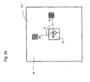
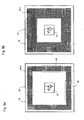
- FIG. 1a shows a schematic representation of an apparatus 10 for measuring the angle of rotation of two relative to each other about an axis of rotation D rotating objects, in particular the rotation of a shaft 16 about the axis of rotation D relative to a stationary object.
- a polarizer 14 is arranged, which in plan view in FIG. 1b is shown, and which is designed as a linear polarizer.
- the polarizer 14 is designed in particular as a disk and has a normal N, which is arranged at a first angle ⁇ to the axis of rotation D.
- the polarizer 14 is thus tilted against the axis of rotation D.
- the polarizer 14 may preferably be formed as a round disc, as in FIG. 1b shown. Alternatively, however, the geometry of the polarizer 14 may take on any shape with regard to bulges and outer contours.
- the polarizer 14 may further be arranged on the shaft 16 such that the normal N does not necessarily have an intersection with the axis of rotation D.
- the polarizer 14 is illuminated with a light source 12.
- the light source 12 has an optical axis A, which is identical to the rotation axis D in the device 10.
- the light source 12 is preferably embodied as an unpolarized light source 12, for example as an LED, but may also be designed as an incandescent lamp or as a coherent light source, for example as a laser or laser diode.
- the light source 12 preferably emits a divergent cone of light to illuminate the polarizer 14 over a large area.
- the light cone of the light source 12 is homogeneous.
- the intensity profile of the light source 12 is preferably rotationally symmetrical, for example with a Lambert or Gaussian distribution and preferably has its intensity center of gravity on the optical axis A.
- the illumination by the light source 12 may also be performed in a collimated or in parts convergent. Beam shaping of the light source 12 is not absolutely necessary. Depending on the embodiment, however, a mirror optics, a refractive or a defractive lens or a combination thereof can be used for the light source 12, the beam shaping advantageously having as little polarization as possible.
- the light source 12 is arranged on a support 18, on which a receiver is arranged.
- the plane of the light source 12 and the plane of the receiver thus coincide in this embodiment.
- the plane of the light source 12 and the plane of the receiver are offset parallel to each other.
- the light source 12 is arranged centrally on the carrier 18.
- a symmetrical design simplifies the evaluation, but is not absolutely necessary. In mutually parallel planes between light source 12 and receiver illumination by a transparent recess in the plane of the receiver or by a beam guide by means of light guides, mirrors, prisms or the like is conceivable.
- the polarizer 14 is reflective and can be designed in particular mirror-reflective, diffuse-reflective or scattering-reflective.
- the light source 12 and the receiver may preferably, in particular including required circuits for signal evaluation on a single plane, for example on the Carrier 18, built-in, resulting in an integrated and cost-effective system.
- the light of the light source 12 is linearly polarized and reflected by the polarizer so that it falls on the receiver.
- Embodiments of the transceiver unit having the light source 12 and the receiver will be described below.
- Figure 1c shows an alternative embodiment of a device 10 'for measuring the angle of rotation of the shaft 16, which differs from the in FIG. 1a only differs in that the polarizer 14 is not arranged on the end face of the shaft 16, but that the shaft 16 is passed through a preferably central recess of the polarizer 14 and the light source 12 and the receiver are arranged such that the optical Axis A of the light source 12 does not coincide with the axis of rotation D and in particular is arranged offset parallel to the axis of rotation D, so that an eccentric illumination of the polarizer 14 results.
- the shaft 16 may be formed in this embodiment as a hollow shaft.
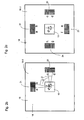
- FIG. 2a shows a first embodiment of a transceiver unit 18-1, which in the devices 10, 10 'according to the FIGS. 1a and 1c can be used.
- the transceiver unit 18-1 has a carrier 18 on which the light source 12 is preferably arranged centrally.
- the transceiver unit 18-1 further comprises two receiving elements a, c, in front of which a respective polarization filter is arranged, which have the same direction of polarization.
- the receiving elements a, c are at an angular distance at a second angle ⁇ with respect to the optical axis A, which when using the transceiver unit 18-1 in the device according to FIG. 1a with the axis of rotation D coincides, arranged.
- the angular distance is in the embodiment 90 °.
- both for the first receiving element a and the second receiving element b each result in a sinusoidal signal with a sinusoidal intensity modulation due to the wobbling motion of the polarizer 14.
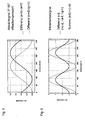
- the relative intensities of the receiving elements a, c in dependence from the angle of rotation are in particular in the FIGS. 3a and 3b shown. This structure thus provides two sine square signals which provide an incremental angle signal.
- the light intensities of the receiving elements c, d provide, as a function of the rotation angle, sinusoidal-shaped signals which are modulated sinusoidally due to the tumbling motion of the polarizer 14 (cf. Fig. 3a and 3b ).
- the two receiving elements a, b provide two squares signals offset by 90 ° (cf. FIG. 3a ). The same applies to the receiving elements c, d (cf. FIG. 3b ).
- the sum of the signals of the receiving elements a, b would result in a constant function without a tumbling motion of the polarizer 14. Since due to the wobbling movement of the polarizer 14 the sinusoidal intensity modulation is superimposed on each of the two individual signals, the sum of the two receiving elements a, b, ie a + b, which is referred to as the first summation signal, yields a sinusoidal signal whose period is one full revolution by 360 ° of the polarizer 14 corresponds (see. FIG. 4a ). The same applies to the first sum signal c + d of the receiving elements c, d (cf. FIG. 4a ).
- the superimposed sinusoidal signals are phase-shifted by 90 ° (vg. FIG. 4a ).
- the absolute angular position from the sine-square signals (see FIGS. FIG. 4a ).
- Figure 2c shows a third embodiment of a transceiver unit 18-3, which differs from the embodiment according to FIG. 2b characterized in that there are two further groups 23, 24, each with two further receiving elements e, f and g, h.
- the third group 23 has the receiving elements e, f, while the fourth group 24 has the receiving elements g, h.
- the polarization directions of the receiving elements e, g correspond to the polarization direction of the receiving elements a, c.
- the polarization directions of the receiving elements f, h correspond to the polarization directions of the receiving elements b, d.
- the receiving elements a, c, e, g with the same direction of polarization are symmetrical about a center of symmetry arranged, in particular in each case at the same angular distance from one another, in particular at an angular distance of 90 °.
- two receiving elements with the same direction of polarization are arranged point-symmetrical to the center of symmetry.
- the center of symmetry lies in particular on the optical axis A and particularly preferably on the axis of rotation D.
- the third group 23 and the fourth group 24 are provided, which each have redundant signals to the reception elements a, b, c, d of the first group 21 and the second group 22 (cf. Figures 3c, 3d such as FIG. 4b ).
- the third group 23 supplies a first summation signal of e + f and the fourth group 24 a first summation signal of g + h (cf. Fig. 4b ).
- the absolute signals can also be offset compensated, as in FIG.
- first difference signals (a + b) - (e + f) or (c + d) - (g + h) are formed, which in FIG. 5 are shown and correspond to an offset-compensated absolute signal.
- the first sum signals can be added by adding the received signals the receiving elements of a group are calculated, but also as a second difference signal, the difference between two of the receiving elements of a group, in particular two receiving elements whose polarization directions are perpendicular to each other.
- the first group 21 results as a second difference signal
- the second group 22 results as a second difference signal cd
- for the third group 23 results as a second difference signal ef
- for the fourth group 24 results as a second difference signal gh.
- the second difference signals of different groups can be added to second sum signals, for example to (ab) + (cd), whereby the signal amplitude is increased and whereby, if necessary, error influences can be minimized (cf. FIG. 6 ).
- the signal stability can be further increased.
- An illumination angle deviating from 90 ° leads to a change in the polarization contrast in most polarizers. Although this only applies to larger angles, for example in the case of wire-grid polarizers at an angle of more than 20 °, in principle this effect can not be avoided.
- the rotation of the tilted polarizer results in a dynamic change in the illumination angle, which in turn leads to a superimposed sinusoidal-shaped intensity modulation on the receiving elements.
- the effect occurs only slightly or not at all in the direction of the polarizing structures of the polarizer, whereas in the 90 ° direction reaches its maximum to these structures. This means that the axis of this error will rotate with the rotation of the polarizer at the receiver level. The effect is not symmetrical at the receiver level.
- At least one group which is located on any other angular range on the receiver plane, ideally offset by 90 °, is needed.
- the signal of the second group which experiences a superimposed intensity modulation of its signal, can be corrected by forming the difference between the signals of both groups taking into account the phase offset of ideally 90 °. This provides the error signal to correct the signal of the second group.
- the prerequisite for this is the prior correction of the intensity fluctuation due to the tumbling of the polarizer and the knowledge of the coarse angular position of the structures on the polarizer, ie the absolute or optionally the incremental angle signal.
- the described correction is also possible over the difference of the respective absolute signals.
- Figure 7a shows a fourth embodiment of a transceiver unit 18-4, which has receiving elements with two different polarization directions, wherein the two polarization directions are rotated in particular by 90 ° to each other.
- the receiving elements are arranged symmetrically about a center of symmetry, which in the present case is formed by the optical axis A of the light source 12 and when using the transceiver unit 18-4 in the device 10 according to FIG. 1a in particular coincides with the axis of rotation D.
- the receiving elements are arranged in particular on a square track around the center of symmetry.
- the transmitting-receiving unit 18-4 has fourteen groups 25, each with two receiving elements, wherein in each group 25, the polarization directions of the receiving elements are each rotated by 90 ° from each other and a total of only two different polarization directions are present.
- the receiving elements of the same direction of polarization are arranged symmetrically with respect to one another, in particular at the same angular distance with respect to the center of symmetry. In particular, two receiving elements with the same direction of polarization are arranged point-symmetrically.
- FIG. 7b shows a fifth embodiment of a transceiver unit 18-5 with eight groups 25 'of receiving elements, wherein in each group 25' each two receiving elements are arranged whose polarization planes are rotated by 90 ° to each other, with a total of only two different polarization directions are present.
- the receiving elements are arranged on an annular track about a center of symmetry, wherein the center of symmetry in particular by the optical Axis A of the light source 12 and, when using the transceiver unit 18-5 in the apparatus according to FIG. 1a, is preferably formed by the axis of rotation D.
- Receiving elements with the same direction of polarization are arranged in the same angular distance from each other. In each case two receiving elements with the same direction of polarization are arranged point-symmetrical to the center of symmetry to each other.
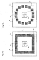
- FIG. 8a shows a sixth embodiment of a transceiver unit 18-6 with receiving elements with four different polarization directions, the polarization directions are rotated by 45 ° from each other.
- the transceiver unit 18-6 has a total of six groups 26, each with four receiving elements, wherein in each group 26, the polarization directions of the receiving elements are rotated by 45 ° from each other, so that in particular each group 26 each have a receiving element with a polarization direction of 0 ° , a receiving element with a polarization direction of 45 °, a receiving element with a polarization direction of 90 ° and a receiving element with a polarization direction of 135 °.
- the receiving elements are arranged symmetrically to a center of symmetry, which is formed in particular by the optical axis A of the light source 12 or the axis of rotation D.
- two receiving elements with the same direction of polarization are arranged point-symmetrically with respect to each other.
- FIG. 8b shows a seventh embodiment of a transceiver unit 18-7 with receiving elements with eight different polarization directions in groups 27, wherein the polarization directions are respectively rotated by 22.5 ° to each other and thus polarization directions at 0 °, 22.5 °, 45 °, 67 , 5 °, 90 °, 112.5 °, 135 °, 157.5 °.
- the reception elements are arranged on two concentrically arranged square tracks around a center of symmetry. Receiving elements with the same polarization direction are arranged point-symmetrically to the center of symmetry, in particular to the optical axis A or the axis of rotation D.
- the groups 27 do not basically have all the polarization directions, but may comprise a different number of reception elements.
- FIG. 8c shows an eighth embodiment of a transceiver unit 18-8 with receiving elements with eight different polarization directions, wherein the polarization directions are respectively rotated by 22.5 ° to each other and thus polarization directions at 0 °, 22.5 °, 45 °, 67.5 ° , 90 °, 112.5 °, 135 °, 157, 5 °.
- the receiving elements are arranged in a total of four square tracks in two nested rows symmetrically about a center of symmetry.
- the center of symmetry is in turn preferably formed by the optical axis A of the light source 12 and particularly preferably by the axis of rotation D.
- two receiving elements with the same direction of polarization are arranged point symmetrical to each other about the center of symmetry.
- the receiving elements of a group are at slightly different positions relative to the center of symmetry as a function of their geometry. This fact can be neglected if the size of the photosensitive surface of the receiving elements is comparatively small and the expected phase error is smaller than the accuracy of the device for determining the angle of rotation. However, if the photosensitive surfaces of the receiving elements could cause a significant error, computational correction can be performed with a priori knowledge of the positioning of the receiving elements at the receiver level. Alternatively, by suitable positioning of the individual groups in a redundant arrangement, a compensation of the effect can be achieved by averaging the intensity over a plurality of identical adjacent receiving elements.
- the receiving elements are shown schematically always square.
- the surface configuration of the receiving elements can be varied depending on the arrangement and manufacturing technology.
- reception elements in the form of squares, rectangles, circles, polygons, diamonds or the like are possible.
- it is advantageous for the signal evaluation if the receiving elements each have the same shape or at least the same area.
- the individual receiving elements can also have different sized areas. This is particularly useful for correction between more inward and outward receiving elements.
- the devices 10, 10 'according to the invention are particularly suitable as a so-called kit solution, in which the transceiver unit 18-1, 18-2, 18-3, 18-4, 18-5, 18-6, 18-7, 18-8 with the light source 12 and the receiver is mechanically decoupled from the polarizer 14, since it can be constructed almost free of adjustment due to the possibilities for correction or compensation of influences of mechanical tolerances.
Landscapes
- Physics & Mathematics (AREA)
- General Physics & Mathematics (AREA)
- Optical Transform (AREA)
Claims (18)
- Dispositif (10) pour mesurer l'angle de rotation de deux objets tournant l'un par rapport à l'autre autour d'un axe de rotation (D), ayant une source lumineuse (12) associée à un objet, un polariseur (14), la source lumineuse (12) et le polariseur (14) tournant l'un par rapport à l'autre en fonction de l'angle de rotation ainsi qu'un récepteur mesurant l'intensité lumineuse traversant le polariseur (14) ou réfléchie par celui-ci, pour générer un signal dépendant de l'angle de rotation, le récepteur ayant au moins un premier élément de réception (a) précédé d'un filtre de polarisation pour une première direction de polarisation,
dispositif caractérisé en ce que
le polariseur (14) est un disque ayant une normale (N) installée suivant un premier angle (α) par rapport à l'axe de rotation (D), cet angle étant différent de 0°, et
le récepteur comporte au moins un second élément récepteur (c) précédé d'un filtre de polarisation, ce second élément récepteur (c) étant à une seconde distance angulaire (β) par rapport au premier élément récepteur (a). - Dispositif selon la revendication 1,
caractérisé en ce que
le premier angle (α) supérieur à 0° et inférieur à 45° est de préférence de l'ordre de 5°. - Dispositif selon l'une des revendications précédentes,
caractérisé en ce que
le second angle (β) est égal à 90°. - Dispositif selon l'une des revendications précédentes,
caractérisé en ce que
la source lumineuse (12) a un axe optique (A) coïncidant avec l'axe de rotation (D). - Dispositif selon l'une des revendications précédentes,
caractérisé en ce que
la source lumineuse (12) se trouve dans un premier plan et le récepteur est dans un second plan, le premier plan correspondant au second plan ou étant décalé parallèlement à celui-ci. - Dispositif selon l'une des revendications précédentes,
caractérisé en ce que
la source lumineuse (12) a un profil de rayonnement divergent et/ou un profil de rayonnement symétrique en rotation. - Dispositif selon l'une des revendications précédentes,
caractérisé en ce que
le premier élément récepteur (a) fait partie d'un premier groupe (21) de (n) éléments récepteurs, (a, b), et chacun des (n) éléments récepteurs (a, b) est précédé d'un élément de polarisation et les directions de polarisation des éléments de polarisation sont tournées l'une par rapport à l'autre de préférence chaque fois de 180°/n, (n) étant le nombre d'éléments récepteurs (a, b) du premier groupe (21) et le second élément récepteur (c) fait partie d'un second groupe (22) de (m) éléments récepteurs (c, d) et chacun des (m) éléments récepteurs (c, d) est précédé d'un élément de polarisation, les directions de polarisation des éléments de polarisation étant tournées l'une par rapport à l'autre, de préférence chaque fois d'un angle de 180°/m, (m) étant le nombre d'éléments récepteurs (c, d) du second groupe (22). - Dispositif selon l'une des revendications précédentes,
caractérisé en ce que
le récepteur comporte au moins quatre ou plus de groupes d'éléments récepteurs, les éléments récepteurs de même direction de polarisation étant de préférence symétriques par rapport à l'axe de rotation (D) ou à l'axe optique (A). - Dispositif selon la revendication 8,
caractérisé en ce que
chaque fois deux éléments récepteurs de même direction de polarisation sont symétriques par rapport à un point, de préférence par rapport à l'axe de rotation (D) ou à l'axe optique (A). - Dispositif selon la revendication 8 ou 9,
caractérisé en ce que
les éléments récepteurs se trouvent sur au moins une trace, de préférence sur deux ou plusieurs traces rectangulaires de préférence carrées ou circulaires, de préférence autour de l'axe de rotation (D) ou de l'axe optique (A). - Dispositif selon l'une des revendications précédentes,
caractérisé en ce que
l'élément récepteur a une ou plusieurs photodiodes de référence. - Dispositif selon l'une quelconque des revendications précédentes,
caractérisé en ce que
la source lumineuse (12), le récepteur et un circuit d'exploitation sont réalisés sous la forme d'un circuit intégré. - Procédé de mesure de l'angle de rotation de deux objets tournant l'un par rapport à l'autre autour d'un axe de rotation (D) avec un dispositif (10, 10') selon l'une des revendications précédentes selon lequel l'intensité lumineuse mesurée par le récepteur est exploitée comme signal dépendant de l'angle de rotation,
procédé caractérisé en ce que
les intensités lumineuses mesurées par les différents éléments récepteurs sont exploitées comme des signaux dépendant de l'angle de rotation. - Procédé selon la revendication 13,
caractérisé en ce que les signaux reçus par les éléments récepteurs d'un groupe sont additionnés pour former un premier signal de somme. - Procédé selon la revendication 14,
caractérisé en ce qu'
on forme un premier signal de différence avec les premiers signaux de somme de deux groupes différents, en particulier de groupes installés de manière symétrique par rapport à un point. - Procédé selon l'une des revendications 13 à 15,
caractérisé en ce qu'
on forme un second signal de différence avec les signaux reçus de deux éléments récepteurs d'un groupe, notamment de deux éléments récepteurs dont les directions de polarisation sont perpendiculaires l'une à l'autre. - Procédé selon la revendication 16,
caractérisé en ce qu'
on forme un second signal de somme avec deux seconds signaux de référence de deux groupes différents, notamment de groupes symétriques l'un par rapport à l'autre par une symétrie par point par rapport à l'axe de rotation. - Procédé selon l'une des revendications 13 à 17,
caractérisé en ce qu'
on fait la moyenne des signaux reçus par les éléments récepteurs et qui correspondent à la même direction de polarisation.
Priority Applications (1)
| Application Number | Priority Date | Filing Date | Title |
|---|---|---|---|
| EP12166058.3A EP2657652B1 (fr) | 2012-04-27 | 2012-04-27 | Dispositif de mesure de l'angle de rotation de deux objets tournant l'un par rapport à l'autre autour d'un axe |
Applications Claiming Priority (1)
| Application Number | Priority Date | Filing Date | Title |
|---|---|---|---|
| EP12166058.3A EP2657652B1 (fr) | 2012-04-27 | 2012-04-27 | Dispositif de mesure de l'angle de rotation de deux objets tournant l'un par rapport à l'autre autour d'un axe |
Publications (2)
| Publication Number | Publication Date |
|---|---|
| EP2657652A1 EP2657652A1 (fr) | 2013-10-30 |
| EP2657652B1 true EP2657652B1 (fr) | 2015-10-28 |
Family
ID=46045899
Family Applications (1)
| Application Number | Title | Priority Date | Filing Date |
|---|---|---|---|
| EP12166058.3A Not-in-force EP2657652B1 (fr) | 2012-04-27 | 2012-04-27 | Dispositif de mesure de l'angle de rotation de deux objets tournant l'un par rapport à l'autre autour d'un axe |
Country Status (1)
| Country | Link |
|---|---|
| EP (1) | EP2657652B1 (fr) |
Families Citing this family (2)
| Publication number | Priority date | Publication date | Assignee | Title |
|---|---|---|---|---|
| JP6369042B2 (ja) | 2013-11-05 | 2018-08-08 | 日本精工株式会社 | 光学式エンコーダユニット及び光学式エンコーダ |
| EP2950056B1 (fr) | 2014-05-26 | 2016-06-08 | SICK STEGMANN GmbH | Dispositif de mesure d'un angle de rotation et procédé de détermination d'un angle de rotation |
Family Cites Families (7)
| Publication number | Priority date | Publication date | Assignee | Title |
|---|---|---|---|---|
| US4597517A (en) | 1985-06-21 | 1986-07-01 | Signode Corporation | Magazine interlock for a fastener driving device |
| JPH0850036A (ja) * | 1994-08-05 | 1996-02-20 | Tokai Rika Co Ltd | ポテンショメータ |
| DE10005277A1 (de) | 2000-02-07 | 2001-08-09 | Bayer Ag | Verfahren zur Herstellung von 2-Chlor-bezimidazol-Derivaten |
| DE20102192U1 (de) | 2001-02-08 | 2001-06-21 | Argast, Martin, 72584 Hülben | Winkelgeber |
| DE10337040B4 (de) | 2003-08-12 | 2013-01-17 | Sick Ag | Vorrichtung zur Untersuchung einer Oberfläche oder einer Schicht |
| US7777879B2 (en) | 2007-02-01 | 2010-08-17 | Stmicroelectronics (Research & Development) Ltd. | Rotary encoders |
| US8395111B2 (en) * | 2010-03-31 | 2013-03-12 | Nxp B.V. | Optical system and method for detecting rotation of an object |
-
2012
- 2012-04-27 EP EP12166058.3A patent/EP2657652B1/fr not_active Not-in-force
Also Published As
| Publication number | Publication date |
|---|---|
| EP2657652A1 (fr) | 2013-10-30 |
Similar Documents
| Publication | Publication Date | Title |
|---|---|---|
| EP2093537B1 (fr) | Système et procédé pour déterminer l'alignement de deux pièces de machine rotatives | |
| EP2108105B1 (fr) | Procédé de détermination d'une grandeur d'influence sur l'excentricité dans un dispositif de mesure d'angle | |
| EP2713142B1 (fr) | Dispositif destiné à mesurer la position relative de deux objets mobiles l'un par rapport à l'autre | |
| DE102010003157B4 (de) | Vorrichtung zur interferentiellen Abstandsmessung | |
| EP2458363B1 (fr) | Mesure des positions de centres de courbures de surfaces optiques d'un système optique à plusieurs lentilles | |
| DE102011011065B4 (de) | Verfahren und Vorrichtung zur hochpräzisen Vermessung von Oberflächen | |
| DE102009012508B3 (de) | Autokollimationsfernrohr mit Kamera | |
| EP2619526B1 (fr) | Lunette autocollimatrice à caméra | |
| EP3764064A1 (fr) | Dispositif optique de mesure de position | |
| EP1271107A1 (fr) | Dispositif de mesure de position | |
| EP1632754B1 (fr) | Méthode et dispositif pour la détermination précise d'un angle de rotation | |
| EP2600113B1 (fr) | Procédé et dispositif de mesure de l'angle de rotation de deux objets tournant l'un par rapport à l'autre | |
| DE10308016A1 (de) | Verschiebungsmessgerät mit Interferenzgitter | |
| EP2657652B1 (fr) | Dispositif de mesure de l'angle de rotation de deux objets tournant l'un par rapport à l'autre autour d'un axe | |
| EP1724548B1 (fr) | Appareil de mesure de position | |
| DE2063541C3 (de) | Elektrooptische Meßvorrichtung zur Vermessung des Trassenverlaufs und des Profilverlaufs einer Gleisstrecke | |
| DE102006052047A1 (de) | Verfahren und Vorrichtung zur Bestimmung der Lage einer Symmetrieachse einer asphärischen Linsenfläche | |
| EP3477264A1 (fr) | Dispositif optique de mesure de position | |
| EP2657653B1 (fr) | Dispositif de mesure de l'angle de rotation de deux objets tournant l'un par rapport à l'autre autour d'un axe | |
| EP2664897B1 (fr) | Encodeur et procédé destinés à la détermination d'une position angulaire | |
| EP2597430B1 (fr) | Dispositif de mesure de l'angle de rotation de deux objets tournant l'un par rapport à l'autre autour d'un axe | |
| EP3236201B1 (fr) | Laser rotatif destiné à déterminer la perpendicularité de deux parties de machine | |
| DE10043828B4 (de) | Abtasteinheit für eine optische Positionsmesseinrichtung | |
| DE102010029920B4 (de) | Optische Positionsmesseinrichtung | |
| DE102010063521A1 (de) | Verfahren zum Ermitteln einer Lageänderung der Rotationsachse eines rotierenden Körpers innerhalb der Rotationsebene |
Legal Events
| Date | Code | Title | Description |
|---|---|---|---|
| PUAI | Public reference made under article 153(3) epc to a published international application that has entered the european phase |
Free format text: ORIGINAL CODE: 0009012 |
|
| 17P | Request for examination filed |
Effective date: 20121221 |
|
| AK | Designated contracting states |
Kind code of ref document: A1 Designated state(s): AL AT BE BG CH CY CZ DE DK EE ES FI FR GB GR HR HU IE IS IT LI LT LU LV MC MK MT NL NO PL PT RO RS SE SI SK SM TR |
|
| AX | Request for extension of the european patent |
Extension state: BA ME |
|
| GRAP | Despatch of communication of intention to grant a patent |
Free format text: ORIGINAL CODE: EPIDOSNIGR1 |
|
| INTG | Intention to grant announced |
Effective date: 20150715 |
|
| GRAS | Grant fee paid |
Free format text: ORIGINAL CODE: EPIDOSNIGR3 |
|
| GRAA | (expected) grant |
Free format text: ORIGINAL CODE: 0009210 |
|
| AK | Designated contracting states |
Kind code of ref document: B1 Designated state(s): AL AT BE BG CH CY CZ DE DK EE ES FI FR GB GR HR HU IE IS IT LI LT LU LV MC MK MT NL NO PL PT RO RS SE SI SK SM TR |
|
| REG | Reference to a national code |
Ref country code: GB Ref legal event code: FG4D Free format text: NOT ENGLISH |
|
| REG | Reference to a national code |
Ref country code: CH Ref legal event code: EP |
|
| REG | Reference to a national code |
Ref country code: AT Ref legal event code: REF Ref document number: 758190 Country of ref document: AT Kind code of ref document: T Effective date: 20151115 |
|
| REG | Reference to a national code |
Ref country code: IE Ref legal event code: FG4D Free format text: LANGUAGE OF EP DOCUMENT: GERMAN |
|
| REG | Reference to a national code |
Ref country code: DE Ref legal event code: R096 Ref document number: 502012005081 Country of ref document: DE |
|
| REG | Reference to a national code |
Ref country code: LT Ref legal event code: MG4D |
|
| REG | Reference to a national code |
Ref country code: NL Ref legal event code: MP Effective date: 20151028 |
|
| PG25 | Lapsed in a contracting state [announced via postgrant information from national office to epo] |
Ref country code: NO Free format text: LAPSE BECAUSE OF FAILURE TO SUBMIT A TRANSLATION OF THE DESCRIPTION OR TO PAY THE FEE WITHIN THE PRESCRIBED TIME-LIMIT Effective date: 20160128 Ref country code: IT Free format text: LAPSE BECAUSE OF FAILURE TO SUBMIT A TRANSLATION OF THE DESCRIPTION OR TO PAY THE FEE WITHIN THE PRESCRIBED TIME-LIMIT Effective date: 20151028 Ref country code: IS Free format text: LAPSE BECAUSE OF FAILURE TO SUBMIT A TRANSLATION OF THE DESCRIPTION OR TO PAY THE FEE WITHIN THE PRESCRIBED TIME-LIMIT Effective date: 20160228 Ref country code: LT Free format text: LAPSE BECAUSE OF FAILURE TO SUBMIT A TRANSLATION OF THE DESCRIPTION OR TO PAY THE FEE WITHIN THE PRESCRIBED TIME-LIMIT Effective date: 20151028 Ref country code: ES Free format text: LAPSE BECAUSE OF FAILURE TO SUBMIT A TRANSLATION OF THE DESCRIPTION OR TO PAY THE FEE WITHIN THE PRESCRIBED TIME-LIMIT Effective date: 20151028 Ref country code: NL Free format text: LAPSE BECAUSE OF FAILURE TO SUBMIT A TRANSLATION OF THE DESCRIPTION OR TO PAY THE FEE WITHIN THE PRESCRIBED TIME-LIMIT Effective date: 20151028 Ref country code: HR Free format text: LAPSE BECAUSE OF FAILURE TO SUBMIT A TRANSLATION OF THE DESCRIPTION OR TO PAY THE FEE WITHIN THE PRESCRIBED TIME-LIMIT Effective date: 20151028 |
|
| PG25 | Lapsed in a contracting state [announced via postgrant information from national office to epo] |
Ref country code: FI Free format text: LAPSE BECAUSE OF FAILURE TO SUBMIT A TRANSLATION OF THE DESCRIPTION OR TO PAY THE FEE WITHIN THE PRESCRIBED TIME-LIMIT Effective date: 20151028 Ref country code: PL Free format text: LAPSE BECAUSE OF FAILURE TO SUBMIT A TRANSLATION OF THE DESCRIPTION OR TO PAY THE FEE WITHIN THE PRESCRIBED TIME-LIMIT Effective date: 20151028 Ref country code: RS Free format text: LAPSE BECAUSE OF FAILURE TO SUBMIT A TRANSLATION OF THE DESCRIPTION OR TO PAY THE FEE WITHIN THE PRESCRIBED TIME-LIMIT Effective date: 20151028 Ref country code: GR Free format text: LAPSE BECAUSE OF FAILURE TO SUBMIT A TRANSLATION OF THE DESCRIPTION OR TO PAY THE FEE WITHIN THE PRESCRIBED TIME-LIMIT Effective date: 20160129 Ref country code: SE Free format text: LAPSE BECAUSE OF FAILURE TO SUBMIT A TRANSLATION OF THE DESCRIPTION OR TO PAY THE FEE WITHIN THE PRESCRIBED TIME-LIMIT Effective date: 20151028 Ref country code: LV Free format text: LAPSE BECAUSE OF FAILURE TO SUBMIT A TRANSLATION OF THE DESCRIPTION OR TO PAY THE FEE WITHIN THE PRESCRIBED TIME-LIMIT Effective date: 20151028 Ref country code: PT Free format text: LAPSE BECAUSE OF FAILURE TO SUBMIT A TRANSLATION OF THE DESCRIPTION OR TO PAY THE FEE WITHIN THE PRESCRIBED TIME-LIMIT Effective date: 20160229 |
|
| PG25 | Lapsed in a contracting state [announced via postgrant information from national office to epo] |
Ref country code: CZ Free format text: LAPSE BECAUSE OF FAILURE TO SUBMIT A TRANSLATION OF THE DESCRIPTION OR TO PAY THE FEE WITHIN THE PRESCRIBED TIME-LIMIT Effective date: 20151028 |
|
| REG | Reference to a national code |
Ref country code: DE Ref legal event code: R097 Ref document number: 502012005081 Country of ref document: DE |
|
| PG25 | Lapsed in a contracting state [announced via postgrant information from national office to epo] |
Ref country code: SM Free format text: LAPSE BECAUSE OF FAILURE TO SUBMIT A TRANSLATION OF THE DESCRIPTION OR TO PAY THE FEE WITHIN THE PRESCRIBED TIME-LIMIT Effective date: 20151028 Ref country code: BE Free format text: LAPSE BECAUSE OF NON-PAYMENT OF DUE FEES Effective date: 20160430 Ref country code: EE Free format text: LAPSE BECAUSE OF FAILURE TO SUBMIT A TRANSLATION OF THE DESCRIPTION OR TO PAY THE FEE WITHIN THE PRESCRIBED TIME-LIMIT Effective date: 20151028 Ref country code: SK Free format text: LAPSE BECAUSE OF FAILURE TO SUBMIT A TRANSLATION OF THE DESCRIPTION OR TO PAY THE FEE WITHIN THE PRESCRIBED TIME-LIMIT Effective date: 20151028 Ref country code: DK Free format text: LAPSE BECAUSE OF FAILURE TO SUBMIT A TRANSLATION OF THE DESCRIPTION OR TO PAY THE FEE WITHIN THE PRESCRIBED TIME-LIMIT Effective date: 20151028 Ref country code: RO Free format text: LAPSE BECAUSE OF FAILURE TO SUBMIT A TRANSLATION OF THE DESCRIPTION OR TO PAY THE FEE WITHIN THE PRESCRIBED TIME-LIMIT Effective date: 20151028 |
|
| PLBE | No opposition filed within time limit |
Free format text: ORIGINAL CODE: 0009261 |
|
| STAA | Information on the status of an ep patent application or granted ep patent |
Free format text: STATUS: NO OPPOSITION FILED WITHIN TIME LIMIT |
|
| 26N | No opposition filed |
Effective date: 20160729 |
|
| PG25 | Lapsed in a contracting state [announced via postgrant information from national office to epo] |
Ref country code: SI Free format text: LAPSE BECAUSE OF FAILURE TO SUBMIT A TRANSLATION OF THE DESCRIPTION OR TO PAY THE FEE WITHIN THE PRESCRIBED TIME-LIMIT Effective date: 20151028 |
|
| REG | Reference to a national code |
Ref country code: CH Ref legal event code: PL |
|
| GBPC | Gb: european patent ceased through non-payment of renewal fee |
Effective date: 20160427 |
|
| PG25 | Lapsed in a contracting state [announced via postgrant information from national office to epo] |
Ref country code: LU Free format text: LAPSE BECAUSE OF FAILURE TO SUBMIT A TRANSLATION OF THE DESCRIPTION OR TO PAY THE FEE WITHIN THE PRESCRIBED TIME-LIMIT Effective date: 20160427 |
|
| REG | Reference to a national code |
Ref country code: IE Ref legal event code: MM4A |
|
| REG | Reference to a national code |
Ref country code: FR Ref legal event code: ST Effective date: 20161230 |
|
| PG25 | Lapsed in a contracting state [announced via postgrant information from national office to epo] |
Ref country code: LI Free format text: LAPSE BECAUSE OF NON-PAYMENT OF DUE FEES Effective date: 20160430 Ref country code: FR Free format text: LAPSE BECAUSE OF NON-PAYMENT OF DUE FEES Effective date: 20160502 Ref country code: GB Free format text: LAPSE BECAUSE OF NON-PAYMENT OF DUE FEES Effective date: 20160427 Ref country code: CH Free format text: LAPSE BECAUSE OF NON-PAYMENT OF DUE FEES Effective date: 20160430 |
|
| PG25 | Lapsed in a contracting state [announced via postgrant information from national office to epo] |
Ref country code: IE Free format text: LAPSE BECAUSE OF NON-PAYMENT OF DUE FEES Effective date: 20160427 |
|
| PG25 | Lapsed in a contracting state [announced via postgrant information from national office to epo] |
Ref country code: HU Free format text: LAPSE BECAUSE OF FAILURE TO SUBMIT A TRANSLATION OF THE DESCRIPTION OR TO PAY THE FEE WITHIN THE PRESCRIBED TIME-LIMIT; INVALID AB INITIO Effective date: 20120427 Ref country code: CY Free format text: LAPSE BECAUSE OF FAILURE TO SUBMIT A TRANSLATION OF THE DESCRIPTION OR TO PAY THE FEE WITHIN THE PRESCRIBED TIME-LIMIT Effective date: 20151028 |
|
| REG | Reference to a national code |
Ref country code: AT Ref legal event code: MM01 Ref document number: 758190 Country of ref document: AT Kind code of ref document: T Effective date: 20170427 |
|
| PG25 | Lapsed in a contracting state [announced via postgrant information from national office to epo] |
Ref country code: MT Free format text: LAPSE BECAUSE OF FAILURE TO SUBMIT A TRANSLATION OF THE DESCRIPTION OR TO PAY THE FEE WITHIN THE PRESCRIBED TIME-LIMIT Effective date: 20151028 Ref country code: MC Free format text: LAPSE BECAUSE OF FAILURE TO SUBMIT A TRANSLATION OF THE DESCRIPTION OR TO PAY THE FEE WITHIN THE PRESCRIBED TIME-LIMIT Effective date: 20151028 Ref country code: MK Free format text: LAPSE BECAUSE OF FAILURE TO SUBMIT A TRANSLATION OF THE DESCRIPTION OR TO PAY THE FEE WITHIN THE PRESCRIBED TIME-LIMIT Effective date: 20151028 Ref country code: TR Free format text: LAPSE BECAUSE OF FAILURE TO SUBMIT A TRANSLATION OF THE DESCRIPTION OR TO PAY THE FEE WITHIN THE PRESCRIBED TIME-LIMIT Effective date: 20151028 |
|
| PG25 | Lapsed in a contracting state [announced via postgrant information from national office to epo] |
Ref country code: BG Free format text: LAPSE BECAUSE OF FAILURE TO SUBMIT A TRANSLATION OF THE DESCRIPTION OR TO PAY THE FEE WITHIN THE PRESCRIBED TIME-LIMIT Effective date: 20151028 |
|
| PG25 | Lapsed in a contracting state [announced via postgrant information from national office to epo] |
Ref country code: AT Free format text: LAPSE BECAUSE OF NON-PAYMENT OF DUE FEES Effective date: 20170427 |
|
| PG25 | Lapsed in a contracting state [announced via postgrant information from national office to epo] |
Ref country code: AL Free format text: LAPSE BECAUSE OF FAILURE TO SUBMIT A TRANSLATION OF THE DESCRIPTION OR TO PAY THE FEE WITHIN THE PRESCRIBED TIME-LIMIT Effective date: 20151028 |
|
| REG | Reference to a national code |
Ref country code: DE Ref legal event code: R082 Ref document number: 502012005081 Country of ref document: DE Ref country code: DE Ref legal event code: R081 Ref document number: 502012005081 Country of ref document: DE Owner name: SICK AG, DE Free format text: FORMER OWNER: SICK STEGMANN GMBH, 78166 DONAUESCHINGEN, DE |
|
| PGFP | Annual fee paid to national office [announced via postgrant information from national office to epo] |
Ref country code: DE Payment date: 20210421 Year of fee payment: 10 |
|
| REG | Reference to a national code |
Ref country code: DE Ref legal event code: R119 Ref document number: 502012005081 Country of ref document: DE |
|
| PG25 | Lapsed in a contracting state [announced via postgrant information from national office to epo] |
Ref country code: DE Free format text: LAPSE BECAUSE OF NON-PAYMENT OF DUE FEES Effective date: 20221103 |