EP2657046A1 - Pneumatic radial tire - Google Patents
Pneumatic radial tire Download PDFInfo
- Publication number
- EP2657046A1 EP2657046A1 EP11850194.9A EP11850194A EP2657046A1 EP 2657046 A1 EP2657046 A1 EP 2657046A1 EP 11850194 A EP11850194 A EP 11850194A EP 2657046 A1 EP2657046 A1 EP 2657046A1
- Authority
- EP
- European Patent Office
- Prior art keywords
- cord
- belt
- carcass
- tire
- pneumatic radial
- Prior art date
- Legal status (The legal status is an assumption and is not a legal conclusion. Google has not performed a legal analysis and makes no representation as to the accuracy of the status listed.)
- Granted
Links
- 239000012779 reinforcing material Substances 0.000 claims abstract description 20
- 239000011324 bead Substances 0.000 claims abstract description 8
- 230000003014 reinforcing effect Effects 0.000 claims abstract description 6
- 229910000831 Steel Inorganic materials 0.000 description 9
- 238000011156 evaluation Methods 0.000 description 9
- 239000010959 steel Substances 0.000 description 9
- 238000000034 method Methods 0.000 description 7
- 238000000926 separation method Methods 0.000 description 7
- XKRFYHLGVUSROY-UHFFFAOYSA-N Argon Chemical compound [Ar] XKRFYHLGVUSROY-UHFFFAOYSA-N 0.000 description 2
- IJGRMHOSHXDMSA-UHFFFAOYSA-N Atomic nitrogen Chemical compound N#N IJGRMHOSHXDMSA-UHFFFAOYSA-N 0.000 description 2
- 230000000694 effects Effects 0.000 description 2
- OKTJSMMVPCPJKN-UHFFFAOYSA-N Carbon Chemical compound [C] OKTJSMMVPCPJKN-UHFFFAOYSA-N 0.000 description 1
- 229910052786 argon Inorganic materials 0.000 description 1
- QVGXLLKOCUKJST-UHFFFAOYSA-N atomic oxygen Chemical compound [O] QVGXLLKOCUKJST-UHFFFAOYSA-N 0.000 description 1
- 238000004364 calculation method Methods 0.000 description 1
- 229910052799 carbon Inorganic materials 0.000 description 1
- 230000000052 comparative effect Effects 0.000 description 1
- 239000000835 fiber Substances 0.000 description 1
- 239000000446 fuel Substances 0.000 description 1
- 239000007789 gas Substances 0.000 description 1
- 239000001307 helium Substances 0.000 description 1
- 229910052734 helium Inorganic materials 0.000 description 1
- SWQJXJOGLNCZEY-UHFFFAOYSA-N helium atom Chemical compound [He] SWQJXJOGLNCZEY-UHFFFAOYSA-N 0.000 description 1
- 239000011261 inert gas Substances 0.000 description 1
- 239000000463 material Substances 0.000 description 1
- 229910052757 nitrogen Inorganic materials 0.000 description 1
- 239000001301 oxygen Substances 0.000 description 1
- 229910052760 oxygen Inorganic materials 0.000 description 1
- 239000013585 weight reducing agent Substances 0.000 description 1
Images


Classifications
-
- B—PERFORMING OPERATIONS; TRANSPORTING
- B60—VEHICLES IN GENERAL
- B60C—VEHICLE TYRES; TYRE INFLATION; TYRE CHANGING; CONNECTING VALVES TO INFLATABLE ELASTIC BODIES IN GENERAL; DEVICES OR ARRANGEMENTS RELATED TO TYRES
- B60C9/00—Reinforcements or ply arrangement of pneumatic tyres
- B60C9/18—Structure or arrangement of belts or breakers, crown-reinforcing or cushioning layers
- B60C9/28—Structure or arrangement of belts or breakers, crown-reinforcing or cushioning layers characterised by the belt or breaker dimensions or curvature relative to carcass
-
- B—PERFORMING OPERATIONS; TRANSPORTING
- B60—VEHICLES IN GENERAL
- B60C—VEHICLE TYRES; TYRE INFLATION; TYRE CHANGING; CONNECTING VALVES TO INFLATABLE ELASTIC BODIES IN GENERAL; DEVICES OR ARRANGEMENTS RELATED TO TYRES
- B60C9/00—Reinforcements or ply arrangement of pneumatic tyres
- B60C9/0007—Reinforcements made of metallic elements, e.g. cords, yarns, filaments or fibres made from metal
-
- B—PERFORMING OPERATIONS; TRANSPORTING
- B60—VEHICLES IN GENERAL
- B60C—VEHICLE TYRES; TYRE INFLATION; TYRE CHANGING; CONNECTING VALVES TO INFLATABLE ELASTIC BODIES IN GENERAL; DEVICES OR ARRANGEMENTS RELATED TO TYRES
- B60C9/00—Reinforcements or ply arrangement of pneumatic tyres
- B60C9/18—Structure or arrangement of belts or breakers, crown-reinforcing or cushioning layers
- B60C9/20—Structure or arrangement of belts or breakers, crown-reinforcing or cushioning layers built-up from rubberised plies each having all cords arranged substantially parallel
- B60C9/2003—Structure or arrangement of belts or breakers, crown-reinforcing or cushioning layers built-up from rubberised plies each having all cords arranged substantially parallel characterised by the materials of the belt cords
- B60C9/2006—Structure or arrangement of belts or breakers, crown-reinforcing or cushioning layers built-up from rubberised plies each having all cords arranged substantially parallel characterised by the materials of the belt cords consisting of steel cord plies only
-
- D—TEXTILES; PAPER
- D07—ROPES; CABLES OTHER THAN ELECTRIC
- D07B—ROPES OR CABLES IN GENERAL
- D07B1/00—Constructional features of ropes or cables
- D07B1/06—Ropes or cables built-up from metal wires, e.g. of section wires around a hemp core
- D07B1/0606—Reinforcing cords for rubber or plastic articles
- D07B1/0613—Reinforcing cords for rubber or plastic articles the reinforcing cords being characterised by the rope configuration
-
- B—PERFORMING OPERATIONS; TRANSPORTING
- B60—VEHICLES IN GENERAL
- B60C—VEHICLE TYRES; TYRE INFLATION; TYRE CHANGING; CONNECTING VALVES TO INFLATABLE ELASTIC BODIES IN GENERAL; DEVICES OR ARRANGEMENTS RELATED TO TYRES
- B60C9/00—Reinforcements or ply arrangement of pneumatic tyres
- B60C9/18—Structure or arrangement of belts or breakers, crown-reinforcing or cushioning layers
- B60C9/20—Structure or arrangement of belts or breakers, crown-reinforcing or cushioning layers built-up from rubberised plies each having all cords arranged substantially parallel
- B60C2009/2061—Physical properties or dimensions of the belt coating rubber
- B60C2009/2067—Thickness
-
- B—PERFORMING OPERATIONS; TRANSPORTING
- B60—VEHICLES IN GENERAL
- B60C—VEHICLE TYRES; TYRE INFLATION; TYRE CHANGING; CONNECTING VALVES TO INFLATABLE ELASTIC BODIES IN GENERAL; DEVICES OR ARRANGEMENTS RELATED TO TYRES
- B60C9/00—Reinforcements or ply arrangement of pneumatic tyres
- B60C9/18—Structure or arrangement of belts or breakers, crown-reinforcing or cushioning layers
- B60C9/20—Structure or arrangement of belts or breakers, crown-reinforcing or cushioning layers built-up from rubberised plies each having all cords arranged substantially parallel
- B60C2009/2074—Physical properties or dimension of the belt cord
- B60C2009/2077—Diameters of the cords; Linear density thereof
-
- B—PERFORMING OPERATIONS; TRANSPORTING
- B60—VEHICLES IN GENERAL
- B60C—VEHICLE TYRES; TYRE INFLATION; TYRE CHANGING; CONNECTING VALVES TO INFLATABLE ELASTIC BODIES IN GENERAL; DEVICES OR ARRANGEMENTS RELATED TO TYRES
- B60C9/00—Reinforcements or ply arrangement of pneumatic tyres
- B60C9/0064—Reinforcements comprising monofilaments
Definitions
- the present invention relates to a pneumatic radial tire (hereinafter, also simply referred to as "tire”), and more particularly, to a pneumatic radial tire having excellent durability and lightweight properties without compromising rigidity.
- a reinforcing member for a carcass constituting a skeleton of a radial tire for passenger vehicle in particular, a belt which is generally used as a reinforcing member for a crown portion of a carcass is mainly constituted such that two or more steel belt layers composed of layers in which rubberized steel cord obliquely arranged with respect to the tire equatorial plane are used, and that the steel cords in the belt layers are crossed each other.
- Patent Document 1 discloses a technique in which several reinforcing elements are used to form a bundle and the bundles are embedded in a belt at a constant interval to improve the durability of the belt.
- Patent Document 2 discloses that, by using as a belt reinforcing material a steel cord having (1 ⁇ 2) structure, separation which occurs at the belt edge can be inhibited and the weight of a tire is reduced.
- an object of the present invention is to provide a pneumatic radial tire having excellent durability and lightweight properties without compromising rigidity.
- the present inventor intensively studied the structure of a belt to find that the above-mentioned problems can be resolved by employing the below-mentioned structure, thereby completing the present invention.
- the pneumatic radial tire of the present invention is a pneumatic radial tire comprising: a carcass composed of at least one carcass layer extending toroidally between a left-and-right pair of bead cores; a tread portion which is arranged on the outside in the tire radial direction of a crown region of the carcass to form a ground contacting portion; and a belt composed of at least two belt layers which is arranged between the tread portion and the crown region of the carcass to form a reinforcing portion, wherein
- the thickness of the belt layer is preferably larger than 0.70 mm and smaller than 1.20 mm.
- the filament diameter is preferably 0.23 to 0.30 mm.
- the cord preferably has a (1 ⁇ 2) structure.
- a pneumatic radial tire having excellent durability and lightweight properties without compromising rigidity can be provided.
- Fig. 1 illustrates a pneumatic radial tire according to one embodiment of the present invention.
- the tire illustrated in the figure comprises a tread portion 1 arranged in a crown region of a carcass to form a ground contacting portion, a pair of sidewall portions 2 continuing to the both sides of the tread portion 1 and extending inward in the tire diameter direction, and a bead portion 3 continuing to the inner radius of each sidewall portion 2.
- the tread portion 1, sidewall portion 2 and bead portion 3 are reinforced by a carcass 4 composed of one carcass layer extending toroidally from one bead portion 3 to the other bead portion 3.
- the tread portion 1 is reinforced by a belt composed of at least two, in the illustrated example, two layers of a first belt layer 5a and a second belt layer 5b which is arranged outside in the tire radial direction of a crown region of the carcass 4 which will be described in detail.
- a plurality of carcass layers may be used for the carcass 4, and an organic fiber cord extending in a direction nearly orthogonal to the tire circumferential direction, for example, in an angle of 70 to 90° is suitably used.
- the reinforcing material constituting the first belt layer 5a and the second belt layer 5b is a bundle formed by arranging two cords without twisting them.
- the interval of the reinforcing materials becomes wider in the belt layer compared to cases where the cords are not formed into a bundle, and a belt edge separation in which rubber separation originated from the cord end in the belt width direction easily propagates into adjacent cords can be inhibited. By this, the durability of the belt can be improved.
- the diameters of all filaments constituting the cord are the same, and, letting the diameter a (mm), the interval between the adjacent bundles as an expected value is increased by a/4 (mm) or larger, preferably by 4a/11 1 (mm) or larger compared to the interval represented by using the circumcircle of the cord.
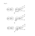
- Figs. 2(a) to (c) are sectional views illustrating an example of change in the cross sections of cord bundles in cases where the bundle 6 is formed by two cords having a (1 ⁇ 2) structure as a reinforcing material for a belt layer; Figs. 3(a) to (c) those in cases where the bundle 16 is formed by two cords having a (1+1) structure.
- change in cord diameter will be explained by way of Fig. 2 and Fig. 3 .
- cord diameter Dc is represented by the diameter of the circumcircle 8 of filament 7 as illustrated in Fig. 2(a) .
- the cord having a (1 ⁇ 2) structure is a cord formed by twisting two filaments 7, the position of the filament 7 continuously changes in the cord (in the circumcircle 8).
- the actual cord diameter in the horizontal direction is smaller than that of the circumcircle 8.
- a cord having a (1+1) structure is used.
- the position of the filament 17 changes as in Figs. 3(a) to (c)
- the actual diameter of cord 16 in the horizontal direction is smaller than that of the circumcircle 18.
- a bundle formed of two cords is used as a belt reinforcing material, and as mentioned above, when the cord diameter changes in the belt width direction, the interval of the adjacent bundles continuously changes in accordance with change in the cord diameter.
- a portion where the interval of the adjacent bundles is wide and a portion where the interval of the adjacent bundles is narrow occur.
- the presence of the portion where the interval of the adjacent bundles is wide allows to more effectively inhibit belt edge separation in which rubber separation originated from the cord end in the belt width direction easily propagates into adjacent cords. As a result, the durability of the belt is further improved. Since there is a portion where the interval of the bundles is narrow, the rigidity of the belt can be maintained.
- FIG. 4 and Fig. 5 are explanatory drawings for calculating an expected value of increment in bundle interval in cases where the bundle is formed by two cords having a (1 ⁇ 2) structure.
- one cord of the adjacent bundles 6 be cord X
- the other cord be cord Y
- the distance between the circumcircle of the cord X and the circumcircle of the cord Y be W.
- FIG. 4(a) a state in which the distance between the circumcircle of the cord X and the circumcircle of the cord Y and the distance between the filament of the cord X and the filament of the cord Y are the same in the horizontal direction be a basic state of cord X and cord Y ( Fig. 4(a) ).
- FIGs. 4(a) to (h) illustrates a cross section of cord X, for example, in a case where the cord X rotates 360° per one pitch, when the cord X is rotated every 45° from the basic state.
- Fig. 4(b) by rotating the cord X 45° from the basic state, the actual distance between the cord X and the cord Y becomes larger than W by xz 2 .
- each of Figs. 5(a) to (h) illustrates a cross section of cord Y, for example, in a case where the cord X rotates 360° per one pitch, when the cord X is rotated every 45° from the basic state.
- the cord Y 45° ( Fig. 5(b) )from the basic state ( Fig. 5(a) ) the actual distance between the cord X and the cord Y becomes larger than W by yz 2 .
- the increment in the distance between the cord X and the cord Y changes from yz 3 to yz 8 .
- cord structures satisfying the above-mentioned relationship include a (1 ⁇ 2) structure and a (1+1) structure.
- the end count of the belt reinforcing material is preferably 35 to 65 counts/50 mm, and more preferably, 40 to 59 counts/50 mm.
- the end count is less than the above-mentioned range, a tensile strength may not be ensured, which is not preferred.
- the end count is more than the above-mentioned range, it becomes difficult to ensure a bundle interval and to effectively inhibit a belt edge separation, which may deteriorate the durability. This is also not preferred.
- the thickness of the belt layer is preferably larger than 0.70 mm and smaller than 1.20 mm.
- the thickness of the belt layer is 0.70 mm or smaller, a sufficient durability may not be obtained.
- the thickness of the belt layer is 1.20 mm or larger, a sufficient light weight effect may not be obtained. More preferably, the thickness is from 0.80 to 1.10 mm.
- the diameter of the filament constituting the cord is preferably 0.23 to 0.30 mm.
- the filament diameter is less than 0.23, a sufficient strength may not be obtained.
- the filament diameter is larger than 0.30, the thickness of the belt becomes thick and sufficient light weight properties may not be obtained.
- conditions such as the direction of twist and twist pitch of each filament are not particularly restricted and can be appropriately configured according to a common procedure depending on the applications.
- the material or the like of the filament is not particularly restricted and steel filament is suitable.
- steel filament those having a tensile strength of, suitably 2700 N/mm 2 or higher can be suitably used.
- a mono filament cord having a high tensile strength those containing at least 0.72 mass%, in particular, at least 0.82 mass% of carbon can be suitably used.
- a gas for filling the tire a normal air or an air in which the oxygen partial pressure is adjusted, as well as an inert gas such as nitrogen, argon or helium can be used.
- Steel cords having a structure as shown in the Table 3 below was used as a belt reinforcing material, and by using the obtained belt reinforcing material, tires of types as shown in Fig. 1 were manufactured in a tire size of 225/45R17.
- the angle of embedded belt reinforcing material was ⁇ 26° with respect to the tire circumferential direction.
- the wear resistance (rigidity), durability and tire weight were evaluated according to the following procedure.
- Steel cords having a structure as shown in the Table 3 below were used as a belt reinforcing material, and by using the obtained belt reinforcing material, tires of types as shown in Fig. 1 were manufactured in a tire size of 225/45R17.
- the angle of embedded belt reinforcing material was ⁇ 26° with respect to the tire circumferential direction.
- the wear resistance (rigidity), durability and tire weight were evaluated according to the following procedure.
- the evaluation was ⁇ as being the same as a conventional product; when the value of the index was larger than 102, the evaluation was o; and when the value of the index was smaller than 98, the evaluation was ⁇ .
- Small wear resistance means a small tread contact area, which is a criteria of rigidity of the belt.
- Each test tire was mounted on a standard rim which is defined in JATMA standards, and then, the tire was inflated to an inner pressure corresponding to the maximum load capability in JATMA YEAR BOOK, which was mounted on a passenger vehicle. After 40,000 km running on a pavement, the tire were dissected and the length of separation at a belt edge portion was investigated. The smaller the value, the better the result. When the result is equal to or the same as the tire of the Conventional Example, the evaluation was ⁇ ; when the result was poorer than the tire of the Conventional Example, the evaluation was ⁇ . The results are listed in Tables 1 to 3 in combination.
- the weight of each tire was measured, and index evaluation was performed by setting the tire of the Conventional Example to 100. When the value was less than 100, the evaluation was ⁇ ; when the value was 100 or higher, the evaluation was ⁇ .
- the results are listed on Tables 1 to 3 in combination.
Landscapes
- Engineering & Computer Science (AREA)
- Mechanical Engineering (AREA)
- Tires In General (AREA)
- Ropes Or Cables (AREA)
Abstract
Description
- The present invention relates to a pneumatic radial tire (hereinafter, also simply referred to as "tire"), and more particularly, to a pneumatic radial tire having excellent durability and lightweight properties without compromising rigidity.
- At present, a reinforcing member for a carcass constituting a skeleton of a radial tire for passenger vehicle, in particular, a belt which is generally used as a reinforcing member for a crown portion of a carcass is mainly constituted such that two or more steel belt layers composed of layers in which rubberized steel cord obliquely arranged with respect to the tire equatorial plane are used, and that the steel cords in the belt layers are crossed each other.
- Conventionally, for the improvement of a belt layer, a variety of studies have been conducted. For example,
Patent Document 1 discloses a technique in which several reinforcing elements are used to form a bundle and the bundles are embedded in a belt at a constant interval to improve the durability of the belt.Patent Document 2 discloses that, by using as a belt reinforcing material a steel cord having (1×2) structure, separation which occurs at the belt edge can be inhibited and the weight of a tire is reduced. -
- Patent Document 1 : Japanese Unexamined Patent Application Publication No.
H 5-213007 - Patent Document 2 : Japanese Unexamined Patent Application Publication No.
S 62-234921 - In recent years, with the enhanced performance of an automobile, an ever-increasing performance of a tire has been demanded. For the improvement of fuel efficiency, weight reduction of a tire is also an important subject. In such circumstances, the belt structures in
Patent Documents - Accordingly, an object of the present invention is to provide a pneumatic radial tire having excellent durability and lightweight properties without compromising rigidity.
- In order to resolve the above-mentioned problems, the present inventor intensively studied the structure of a belt to find that the above-mentioned problems can be resolved by employing the below-mentioned structure, thereby completing the present invention.
- Specifically, the pneumatic radial tire of the present invention is a pneumatic radial tire comprising: a carcass composed of at least one carcass layer extending toroidally between a left-and-right pair of bead cores; a tread portion which is arranged on the outside in the tire radial direction of a crown region of the carcass to form a ground contacting portion; and a belt composed of at least two belt layers which is arranged between the tread portion and the crown region of the carcass to form a reinforcing portion, wherein
- a reinforcing material constituting the belt layer is a bundle formed by arranging two cords without twisting them; and the diameters of all filaments constituting the cord are the same, and, letting the diameter a (mm), the interval between the adjacent bundles as an expected value is increased by a/4 (mm) or larger compared to the interval represented by using the circumcircle of the cord.
- In the present invention, the thickness of the belt layer is preferably larger than 0.70 mm and smaller than 1.20 mm. In the present invention, the filament diameter is preferably 0.23 to 0.30 mm. Further, in the present invention, the cord preferably has a (1×2) structure.
- By the present invention, a pneumatic radial tire having excellent durability and lightweight properties without compromising rigidity can be provided.
-
-
Fig. 1 is a half sectional view illustrating one preferred example a pneumatic tire of the present invention. -
Fig. 2 is a sectional view illustrating an example of change in the cross section of bundles in cases where the bundle is formed by two cords having a (1×2) structure. -
Fig. 3 is a sectional view illustrating an example of change in the cross section of bundles in cases where the bundle is formed by two cords having a (1+1) structure. -
Fig. 4 is an explanatory drawing for calculating an expected value of increment in bundle interval in cases where the bundle is formed by two cords having a (1×2) structure. -
Fig. 5 is an explanatory drawing for calculating an expected value of increment in bundle interval in cases where the bundle is formed by two cords having a (1×2) structure. - In the following, embodiments of the present invention will be described in detail.
-
Fig. 1 illustrates a pneumatic radial tire according to one embodiment of the present invention. The tire illustrated in the figure comprises atread portion 1 arranged in a crown region of a carcass to form a ground contacting portion, a pair ofsidewall portions 2 continuing to the both sides of thetread portion 1 and extending inward in the tire diameter direction, and a bead portion 3 continuing to the inner radius of eachsidewall portion 2. - The
tread portion 1,sidewall portion 2 and bead portion 3 are reinforced by acarcass 4 composed of one carcass layer extending toroidally from one bead portion 3 to the other bead portion 3. Thetread portion 1 is reinforced by a belt composed of at least two, in the illustrated example, two layers of afirst belt layer 5a and asecond belt layer 5b which is arranged outside in the tire radial direction of a crown region of thecarcass 4 which will be described in detail. Here, a plurality of carcass layers may be used for thecarcass 4, and an organic fiber cord extending in a direction nearly orthogonal to the tire circumferential direction, for example, in an angle of 70 to 90° is suitably used. - In the present invention, the reinforcing material constituting the
first belt layer 5a and thesecond belt layer 5b is a bundle formed by arranging two cords without twisting them. By employing as a reinforcing material a bundle formed of two cords, the interval of the reinforcing materials becomes wider in the belt layer compared to cases where the cords are not formed into a bundle, and a belt edge separation in which rubber separation originated from the cord end in the belt width direction easily propagates into adjacent cords can be inhibited. By this, the durability of the belt can be improved. In the present invention, the diameters of all filaments constituting the cord are the same, and, letting the diameter a (mm), the interval between the adjacent bundles as an expected value is increased by a/4 (mm) or larger, preferably by 4a/11 1 (mm) or larger compared to the interval represented by using the circumcircle of the cord.Figs. 2(a) to (c) are sectional views illustrating an example of change in the cross sections of cord bundles in cases where thebundle 6 is formed by two cords having a (1×2) structure as a reinforcing material for a belt layer;Figs. 3(a) to (c) those in cases where thebundle 16 is formed by two cords having a (1+1) structure. First, change in cord diameter will be explained by way ofFig. 2 andFig. 3 . - Normally, cord diameter Dc is represented by the diameter of the
circumcircle 8 offilament 7 as illustrated inFig. 2(a) . However, since the cord having a (1×2) structure is a cord formed by twisting twofilaments 7, the position of thefilament 7 continuously changes in the cord (in the circumcircle 8). For example, when the position of thefilament 7 changes by 45° as inFigs. 2(b), (c) , the actual cord diameter in the horizontal direction is smaller than that of thecircumcircle 8. This is also true in cases where a cord having a (1+1) structure is used. As illustrated inFigs. 3(a) to (c) , when the position of thefilament 17 changes as inFigs. 3(a) to (c) , the actual diameter ofcord 16 in the horizontal direction is smaller than that of thecircumcircle 18. - In the tire of the present invention, a bundle formed of two cords is used as a belt reinforcing material, and as mentioned above, when the cord diameter changes in the belt width direction, the interval of the adjacent bundles continuously changes in accordance with change in the cord diameter. In other words, a portion where the interval of the adjacent bundles is wide and a portion where the interval of the adjacent bundles is narrow occur. The presence of the portion where the interval of the adjacent bundles is wide allows to more effectively inhibit belt edge separation in which rubber separation originated from the cord end in the belt width direction easily propagates into adjacent cords. As a result, the durability of the belt is further improved. Since there is a portion where the interval of the bundles is narrow, the rigidity of the belt can be maintained.
- Next, the calculation method of an expected value of increment in bundle interval will be explained.
Fig. 4 andFig. 5 are explanatory drawings for calculating an expected value of increment in bundle interval in cases where the bundle is formed by two cords having a (1×2) structure. First, as illustrated inFig. 4(a) , let one cord of theadjacent bundles 6 be cord X the other cord be cord Y, and the distance between the circumcircle of the cord X and the circumcircle of the cord Y be W. Next, let a state in which the distance between the circumcircle of the cord X and the circumcircle of the cord Y and the distance between the filament of the cord X and the filament of the cord Y are the same in the horizontal direction be a basic state of cord X and cord Y (Fig. 4(a) ). Each ofFigs. 4(a) to (h) illustrates a cross section of cord X, for example, in a case where the cord X rotates 360° per one pitch, when the cord X is rotated every 45° from the basic state. With reference toFig. 4(b) , by rotating the cord X 45° from the basic state, the actual distance between the cord X and the cord Y becomes larger than W by xz2. Further, when the cord X is rotated every 45° (Figs. 4(c) to (h) ), the increment in the distance between the cord X and the cord Y changes from xz3 to xz8. xz1 in a basic state (Fig. 4(a) ) and xz5 in a state where the cord X is rotated 180° from the basic state (Fig. 4(e) ) are 0. - Similarly, in the case of cord Y, each of
Figs. 5(a) to (h) illustrates a cross section of cord Y, for example, in a case where the cord X rotates 360° per one pitch, when the cord X is rotated every 45° from the basic state. By rotating the cord Y 45° (Fig. 5(b) )from the basic state (Fig. 5(a) ), the actual distance between the cord X and the cord Y becomes larger than W by yz2. Further, when the cord X is rotated every 45° (Figs. 5(c) to (h) ), the increment in the distance between the cord X and the cord Y changes from yz3 to yz8. - In the above, as a method of calculating the increment in the bundle interval has described by way of an example where the cord X and the cord Y are rotated 45° individually. In the present invention, based on a similar idea, in a case where a cord X and cord Y rotate 360° per one pitch, the cord X and cord Y are rotated every 1° from the basic state to determine xz1 to xz360 and yz1 to yz360. Based on the obtained value, an expected value of increment in bundle interval is calculated by the following formula:

Although a case where the cord has a (1×2) structure has been explained as an example, for a cord having other structures, an expected value of increment in bundle interval can be calculated in the same procedure. - By using a bundle of two cords in which the expected value of increment in bundle interval calculated by the above-mentioned formula is increased by a/4 (mm) or larger, preferably 4a/11 (mm) or larger as a belt reinforcing material, a pneumatic radial tire having excellent durability and lightweight properties without compromising rigidity can be obtained. Examples of cord structures satisfying the above-mentioned relationship include a (1×2) structure and a (1+1) structure.
- In the present invention, the end count of the belt reinforcing material is preferably 35 to 65 counts/50 mm, and more preferably, 40 to 59 counts/50 mm. When the end count is less than the above-mentioned range, a tensile strength may not be ensured, which is not preferred. On the other hand, when the end count is more than the above-mentioned range, it becomes difficult to ensure a bundle interval and to effectively inhibit a belt edge separation, which may deteriorate the durability. This is also not preferred.
- In the present invention, from the viewpoint of reducing the weight of a tire and improving the durability of a tire, the thickness of the belt layer is preferably larger than 0.70 mm and smaller than 1.20 mm. When the thickness of the belt layer is 0.70 mm or smaller, a sufficient durability may not be obtained. On the other hand, when the thickness of the belt layer is 1.20 mm or larger, a sufficient light weight effect may not be obtained. More preferably, the thickness is from 0.80 to 1.10 mm.
- In the present invention, the diameter of the filament constituting the cord is preferably 0.23 to 0.30 mm. When the filament diameter is less than 0.23, a sufficient strength may not be obtained. On the other hand, when the filament diameter is larger than 0.30, the thickness of the belt becomes thick and sufficient light weight properties may not be obtained.
- In the present invention, conditions such as the direction of twist and twist pitch of each filament are not particularly restricted and can be appropriately configured according to a common procedure depending on the applications. The material or the like of the filament is not particularly restricted and steel filament is suitable. As the steel filament, those having a tensile strength of, suitably 2700 N/mm2 or higher can be suitably used. As a mono filament cord having a high tensile strength, those containing at least 0.72 mass%, in particular, at least 0.82 mass% of carbon can be suitably used.
- Other specific tire structures of the pneumatic radial tire of the present invention are not particularly restricted as long as the structure of the belt satisfies the above-mentioned requirements. As a gas for filling the tire, a normal air or an air in which the oxygen partial pressure is adjusted, as well as an inert gas such as nitrogen, argon or helium can be used.
- In the following, the present invention will be described in detail by way of Examples.
- Two steel cords having a structure as shown in the Tables 1 and 2 below were used to form a bundle and the bundle was employed as a belt reinforcing material, and by using the obtained belt reinforcing material, tires of types as shown in
Fig. 1 were manufactured in a tire size of 225/45R17. The angle of embedded belt reinforcing material was ±26° with respect to the tire circumferential direction. For each of the obtained tires, the wear resistance (rigidity), durability and tire weight were evaluated according to the following procedure. - Steel cords having a structure as shown in the Table 3 below was used as a belt reinforcing material, and by using the obtained belt reinforcing material, tires of types as shown in
Fig. 1 were manufactured in a tire size of 225/45R17. The angle of embedded belt reinforcing material was ±26° with respect to the tire circumferential direction. For each of the obtained tires, the wear resistance (rigidity), durability and tire weight were evaluated according to the following procedure. - Steel cords having a structure as shown in the Table 3 below were used as a belt reinforcing material, and by using the obtained belt reinforcing material, tires of types as shown in
Fig. 1 were manufactured in a tire size of 225/45R17. The angle of embedded belt reinforcing material was ±26° with respect to the tire circumferential direction. For each of the obtained tires, the wear resistance (rigidity), durability and tire weight were evaluated according to the following procedure. - A tire groove depth (center rib groove) remaining after endurance running of an actual vehicle (20 runs of existing circuit which is 3.5 km in length in a limit running mode) was measured to evaluate the tire, and an index evaluation was performed by setting a tire of the Conventional Example to 100. When the value of the index was 100±2, the evaluation was Δ as being the same as a conventional product; when the value of the index was larger than 102, the evaluation was o; and when the value of the index was smaller than 98, the evaluation was ×. The results are listed on Tables 1 to 3 in combination. Small wear resistance means a small tread contact area, which is a criteria of rigidity of the belt.
- Each test tire was mounted on a standard rim which is defined in JATMA standards, and then, the tire was inflated to an inner pressure corresponding to the maximum load capability in JATMA YEAR BOOK, which was mounted on a passenger vehicle. After 40,000 km running on a pavement, the tire were dissected and the length of separation at a belt edge portion was investigated. The smaller the value, the better the result. When the result is equal to or the same as the tire of the Conventional Example, the evaluation was ○; when the result was poorer than the tire of the Conventional Example, the evaluation was ×. The results are listed in Tables 1 to 3 in combination.
- The weight of each tire was measured, and index evaluation was performed by setting the tire of the Conventional Example to 100. When the value was less than 100, the evaluation was ○; when the value was 100 or higher, the evaluation was ×. The results are listed on Tables 1 to 3 in combination.


- By the Tables 1 to 3, it is confirmed that the tire of the present invention had excellent durability and lightweight properties without compromising rigidity.
-
- 1
- Tread portion
- 2
- Sidewall portion
- 3
- Bead portion
- 4
- Carcass
- 5a
- First belt layer
- 5b
- Second belt layer
- 6, 16
- Bundle
- 7, 17
- Filament
- 8, 18
- Circumcircle
Claims (4)
- A pneumatic radial tire comprising: a carcass composed of at least one carcass layer extending toroidally between a left-and-right pair of bead cores; a tread portion which is arranged on the outside in the tire radial direction of a crown region of the carcass to form a ground contacting portion; and a belt composed of at least two belt layers which is arranged between the tread portion and the crown region of the carcass to form a reinforcing portion, wherein
a reinforcing material constituting the belt layer is a bundle formed by arranging two cords without twisting them; and the diameters of all filaments constituting the cord are the same, and, letting the diameter a (mm), the interval between the adjacent bundles as an expected value is increased by a/4 (mm) or larger compared to the interval represented by using the circumcircle of the cord. - The pneumatic radial tire according to claim 1, wherein the thickness of the belt layer is larger than 0.70 mm and smaller than 1.20 mm.
- The pneumatic radial tire according to claim 1, wherein the filament diameter is from 0.23 to 0.30 mm.
- The pneumatic radial tire according to claim 1, wherein the cord has a (1×2) structure.
Applications Claiming Priority (2)
| Application Number | Priority Date | Filing Date | Title |
|---|---|---|---|
| JP2010285044A JP5718041B2 (en) | 2010-12-21 | 2010-12-21 | Pneumatic radial tire |
| PCT/JP2011/079377 WO2012086594A1 (en) | 2010-12-21 | 2011-12-19 | Pneumatic radial tire |
Publications (3)
| Publication Number | Publication Date |
|---|---|
| EP2657046A1 true EP2657046A1 (en) | 2013-10-30 |
| EP2657046A4 EP2657046A4 (en) | 2016-07-27 |
| EP2657046B1 EP2657046B1 (en) | 2018-02-21 |
Family
ID=46313864
Family Applications (1)
| Application Number | Title | Priority Date | Filing Date |
|---|---|---|---|
| EP11850194.9A Active EP2657046B1 (en) | 2010-12-21 | 2011-12-19 | Pneumatic radial tire |
Country Status (5)
| Country | Link |
|---|---|
| US (1) | US9333805B2 (en) |
| EP (1) | EP2657046B1 (en) |
| JP (1) | JP5718041B2 (en) |
| CN (1) | CN103269880B (en) |
| WO (1) | WO2012086594A1 (en) |
Cited By (2)
| Publication number | Priority date | Publication date | Assignee | Title |
|---|---|---|---|---|
| EP3501848A4 (en) * | 2016-08-17 | 2019-06-26 | Bridgestone Corporation | Pneumatic tire |
| US20210291592A1 (en) * | 2020-03-17 | 2021-09-23 | The Goodyear Tire & Rubber Company | Tire and a rubber ply for a tire |
Families Citing this family (1)
| Publication number | Priority date | Publication date | Assignee | Title |
|---|---|---|---|---|
| EP3868570B1 (en) | 2018-10-17 | 2024-01-24 | Bridgestone Corporation | Tire |
Family Cites Families (10)
| Publication number | Priority date | Publication date | Assignee | Title |
|---|---|---|---|---|
| MY100832A (en) | 1986-03-06 | 1991-03-15 | Goodyear Tire & Rubber | Reinforced composite structure |
| JP2646390B2 (en) * | 1989-02-27 | 1997-08-27 | 横浜ゴム株式会社 | Pneumatic radial tire |
| US5827381A (en) * | 1990-08-10 | 1998-10-27 | Bridgestone Corporation | Pneumatic radial tires including a tire component containing groups of reinforcing elements |
| JP2713806B2 (en) * | 1990-08-10 | 1998-02-16 | 株式会社ブリヂストン | Radial tire |
| JP3020184B2 (en) * | 1991-07-08 | 2000-03-15 | 横浜ゴム株式会社 | Pneumatic radial tires for passenger cars |
| JP3124608B2 (en) * | 1992-02-03 | 2001-01-15 | 株式会社ブリヂストン | Pneumatic radial tire |
| JP2904688B2 (en) * | 1993-10-20 | 1999-06-14 | 横浜ゴム株式会社 | Pneumatic radial tire for heavy loads |
| JP2001334810A (en) * | 2000-05-29 | 2001-12-04 | Bridgestone Corp | Pneumatic radial tire |
| JP3995956B2 (en) * | 2002-02-26 | 2007-10-24 | 不二精工株式会社 | Pneumatic tire and manufacturing method thereof |
| JP2007302203A (en) | 2006-05-15 | 2007-11-22 | Bridgestone Corp | Pneumatic tire |
-
2010
- 2010-12-21 JP JP2010285044A patent/JP5718041B2/en active Active
-
2011
- 2011-12-19 EP EP11850194.9A patent/EP2657046B1/en active Active
- 2011-12-19 US US13/992,812 patent/US9333805B2/en active Active
- 2011-12-19 CN CN201180062101.6A patent/CN103269880B/en active Active
- 2011-12-19 WO PCT/JP2011/079377 patent/WO2012086594A1/en active Application Filing
Cited By (3)
| Publication number | Priority date | Publication date | Assignee | Title |
|---|---|---|---|---|
| EP3501848A4 (en) * | 2016-08-17 | 2019-06-26 | Bridgestone Corporation | Pneumatic tire |
| US11273674B2 (en) | 2016-08-17 | 2022-03-15 | Bridgestone Corporation | Pneumatic tire |
| US20210291592A1 (en) * | 2020-03-17 | 2021-09-23 | The Goodyear Tire & Rubber Company | Tire and a rubber ply for a tire |
Also Published As
| Publication number | Publication date |
|---|---|
| US20130263994A1 (en) | 2013-10-10 |
| JP2012131364A (en) | 2012-07-12 |
| WO2012086594A1 (en) | 2012-06-28 |
| CN103269880B (en) | 2017-06-13 |
| JP5718041B2 (en) | 2015-05-13 |
| US9333805B2 (en) | 2016-05-10 |
| EP2657046B1 (en) | 2018-02-21 |
| CN103269880A (en) | 2013-08-28 |
| EP2657046A4 (en) | 2016-07-27 |
Similar Documents
| Publication | Publication Date | Title |
|---|---|---|
| EP2689939B1 (en) | Steel cord for rubber article reinforcement and pneumatic radial tire using same | |
| US10166819B2 (en) | Pneumatic tire | |
| EP2639082B1 (en) | Pneumatic tire | |
| WO2012081624A1 (en) | Steel cord for reinforcing rubber article, and pneumatic tire using same | |
| EP3098088B1 (en) | Motorcycle tire | |
| JP2007107136A (en) | Steel cord for reinforcing rubber article and pneumatic radial tire | |
| EP2657046A1 (en) | Pneumatic radial tire | |
| EP3132948A1 (en) | Tire | |
| JP2012171364A (en) | Pneumatic radial tire | |
| JP2012091614A (en) | Pneumatic radial tire | |
| JP5309869B2 (en) | Pneumatic radial tire for passenger cars | |
| JP2010089725A (en) | Pneumatic tire for automobile | |
| JP2009173150A (en) | Radial tire | |
| JP2013199195A (en) | Pneumatic radial tire | |
| JP5945140B2 (en) | Pneumatic radial tire | |
| JP6022752B2 (en) | Pneumatic radial tire | |
| JP5718085B2 (en) | Pneumatic tire | |
| JP2013159250A (en) | Pneumatic radial tire | |
| JP2013199189A (en) | Pneumatic radial tire | |
| WO2018142691A1 (en) | Tier | |
| JP5945141B2 (en) | Pneumatic radial tire | |
| JP6017114B2 (en) | Pneumatic tire | |
| JP2012131367A (en) | Pneumatic radial tire | |
| JP2013199194A (en) | Pneumatic radial tire | |
| JP2014008866A (en) | Pneumatic radial tire |
Legal Events
| Date | Code | Title | Description |
|---|---|---|---|
| PUAI | Public reference made under article 153(3) epc to a published international application that has entered the european phase |
Free format text: ORIGINAL CODE: 0009012 |
|
| 17P | Request for examination filed |
Effective date: 20130621 |
|
| AK | Designated contracting states |
Kind code of ref document: A1 Designated state(s): AL AT BE BG CH CY CZ DE DK EE ES FI FR GB GR HR HU IE IS IT LI LT LU LV MC MK MT NL NO PL PT RO RS SE SI SK SM TR |
|
| DAX | Request for extension of the european patent (deleted) | ||
| RA4 | Supplementary search report drawn up and despatched (corrected) |
Effective date: 20160629 |
|
| RIC1 | Information provided on ipc code assigned before grant |
Ipc: B60C 9/00 20060101ALI20160623BHEP Ipc: D07B 1/06 20060101ALI20160623BHEP Ipc: B60C 9/20 20060101AFI20160623BHEP |
|
| GRAP | Despatch of communication of intention to grant a patent |
Free format text: ORIGINAL CODE: EPIDOSNIGR1 |
|
| INTG | Intention to grant announced |
Effective date: 20170823 |
|
| GRAS | Grant fee paid |
Free format text: ORIGINAL CODE: EPIDOSNIGR3 |
|
| GRAA | (expected) grant |
Free format text: ORIGINAL CODE: 0009210 |
|
| AK | Designated contracting states |
Kind code of ref document: B1 Designated state(s): AL AT BE BG CH CY CZ DE DK EE ES FI FR GB GR HR HU IE IS IT LI LT LU LV MC MK MT NL NO PL PT RO RS SE SI SK SM TR |
|
| REG | Reference to a national code |
Ref country code: GB Ref legal event code: FG4D |
|
| REG | Reference to a national code |
Ref country code: CH Ref legal event code: EP |
|
| REG | Reference to a national code |
Ref country code: AT Ref legal event code: REF Ref document number: 971301 Country of ref document: AT Kind code of ref document: T Effective date: 20180315 |
|
| REG | Reference to a national code |
Ref country code: IE Ref legal event code: FG4D |
|
| REG | Reference to a national code |
Ref country code: DE Ref legal event code: R096 Ref document number: 602011045908 Country of ref document: DE |
|
| REG | Reference to a national code |
Ref country code: NL Ref legal event code: MP Effective date: 20180221 |
|
| REG | Reference to a national code |
Ref country code: LT Ref legal event code: MG4D |
|
| REG | Reference to a national code |
Ref country code: AT Ref legal event code: MK05 Ref document number: 971301 Country of ref document: AT Kind code of ref document: T Effective date: 20180221 |
|
| PG25 | Lapsed in a contracting state [announced via postgrant information from national office to epo] |
Ref country code: HR Free format text: LAPSE BECAUSE OF FAILURE TO SUBMIT A TRANSLATION OF THE DESCRIPTION OR TO PAY THE FEE WITHIN THE PRESCRIBED TIME-LIMIT Effective date: 20180221 Ref country code: LT Free format text: LAPSE BECAUSE OF FAILURE TO SUBMIT A TRANSLATION OF THE DESCRIPTION OR TO PAY THE FEE WITHIN THE PRESCRIBED TIME-LIMIT Effective date: 20180221 Ref country code: CY Free format text: LAPSE BECAUSE OF FAILURE TO SUBMIT A TRANSLATION OF THE DESCRIPTION OR TO PAY THE FEE WITHIN THE PRESCRIBED TIME-LIMIT Effective date: 20180221 Ref country code: FI Free format text: LAPSE BECAUSE OF FAILURE TO SUBMIT A TRANSLATION OF THE DESCRIPTION OR TO PAY THE FEE WITHIN THE PRESCRIBED TIME-LIMIT Effective date: 20180221 Ref country code: NO Free format text: LAPSE BECAUSE OF FAILURE TO SUBMIT A TRANSLATION OF THE DESCRIPTION OR TO PAY THE FEE WITHIN THE PRESCRIBED TIME-LIMIT Effective date: 20180521 Ref country code: ES Free format text: LAPSE BECAUSE OF FAILURE TO SUBMIT A TRANSLATION OF THE DESCRIPTION OR TO PAY THE FEE WITHIN THE PRESCRIBED TIME-LIMIT Effective date: 20180221 Ref country code: NL Free format text: LAPSE BECAUSE OF FAILURE TO SUBMIT A TRANSLATION OF THE DESCRIPTION OR TO PAY THE FEE WITHIN THE PRESCRIBED TIME-LIMIT Effective date: 20180221 |
|
| PG25 | Lapsed in a contracting state [announced via postgrant information from national office to epo] |
Ref country code: AT Free format text: LAPSE BECAUSE OF FAILURE TO SUBMIT A TRANSLATION OF THE DESCRIPTION OR TO PAY THE FEE WITHIN THE PRESCRIBED TIME-LIMIT Effective date: 20180221 Ref country code: SE Free format text: LAPSE BECAUSE OF FAILURE TO SUBMIT A TRANSLATION OF THE DESCRIPTION OR TO PAY THE FEE WITHIN THE PRESCRIBED TIME-LIMIT Effective date: 20180221 Ref country code: LV Free format text: LAPSE BECAUSE OF FAILURE TO SUBMIT A TRANSLATION OF THE DESCRIPTION OR TO PAY THE FEE WITHIN THE PRESCRIBED TIME-LIMIT Effective date: 20180221 Ref country code: RS Free format text: LAPSE BECAUSE OF FAILURE TO SUBMIT A TRANSLATION OF THE DESCRIPTION OR TO PAY THE FEE WITHIN THE PRESCRIBED TIME-LIMIT Effective date: 20180221 Ref country code: GR Free format text: LAPSE BECAUSE OF FAILURE TO SUBMIT A TRANSLATION OF THE DESCRIPTION OR TO PAY THE FEE WITHIN THE PRESCRIBED TIME-LIMIT Effective date: 20180522 Ref country code: BG Free format text: LAPSE BECAUSE OF FAILURE TO SUBMIT A TRANSLATION OF THE DESCRIPTION OR TO PAY THE FEE WITHIN THE PRESCRIBED TIME-LIMIT Effective date: 20180521 |
|
| PG25 | Lapsed in a contracting state [announced via postgrant information from national office to epo] |
Ref country code: AL Free format text: LAPSE BECAUSE OF FAILURE TO SUBMIT A TRANSLATION OF THE DESCRIPTION OR TO PAY THE FEE WITHIN THE PRESCRIBED TIME-LIMIT Effective date: 20180221 Ref country code: EE Free format text: LAPSE BECAUSE OF FAILURE TO SUBMIT A TRANSLATION OF THE DESCRIPTION OR TO PAY THE FEE WITHIN THE PRESCRIBED TIME-LIMIT Effective date: 20180221 Ref country code: IT Free format text: LAPSE BECAUSE OF FAILURE TO SUBMIT A TRANSLATION OF THE DESCRIPTION OR TO PAY THE FEE WITHIN THE PRESCRIBED TIME-LIMIT Effective date: 20180221 Ref country code: RO Free format text: LAPSE BECAUSE OF FAILURE TO SUBMIT A TRANSLATION OF THE DESCRIPTION OR TO PAY THE FEE WITHIN THE PRESCRIBED TIME-LIMIT Effective date: 20180221 Ref country code: PL Free format text: LAPSE BECAUSE OF FAILURE TO SUBMIT A TRANSLATION OF THE DESCRIPTION OR TO PAY THE FEE WITHIN THE PRESCRIBED TIME-LIMIT Effective date: 20180221 |
|
| REG | Reference to a national code |
Ref country code: DE Ref legal event code: R097 Ref document number: 602011045908 Country of ref document: DE |
|
| PG25 | Lapsed in a contracting state [announced via postgrant information from national office to epo] |
Ref country code: SK Free format text: LAPSE BECAUSE OF FAILURE TO SUBMIT A TRANSLATION OF THE DESCRIPTION OR TO PAY THE FEE WITHIN THE PRESCRIBED TIME-LIMIT Effective date: 20180221 Ref country code: CZ Free format text: LAPSE BECAUSE OF FAILURE TO SUBMIT A TRANSLATION OF THE DESCRIPTION OR TO PAY THE FEE WITHIN THE PRESCRIBED TIME-LIMIT Effective date: 20180221 Ref country code: DK Free format text: LAPSE BECAUSE OF FAILURE TO SUBMIT A TRANSLATION OF THE DESCRIPTION OR TO PAY THE FEE WITHIN THE PRESCRIBED TIME-LIMIT Effective date: 20180221 Ref country code: SM Free format text: LAPSE BECAUSE OF FAILURE TO SUBMIT A TRANSLATION OF THE DESCRIPTION OR TO PAY THE FEE WITHIN THE PRESCRIBED TIME-LIMIT Effective date: 20180221 |
|
| PLBE | No opposition filed within time limit |
Free format text: ORIGINAL CODE: 0009261 |
|
| STAA | Information on the status of an ep patent application or granted ep patent |
Free format text: STATUS: NO OPPOSITION FILED WITHIN TIME LIMIT |
|
| 26N | No opposition filed |
Effective date: 20181122 |
|
| PG25 | Lapsed in a contracting state [announced via postgrant information from national office to epo] |
Ref country code: SI Free format text: LAPSE BECAUSE OF FAILURE TO SUBMIT A TRANSLATION OF THE DESCRIPTION OR TO PAY THE FEE WITHIN THE PRESCRIBED TIME-LIMIT Effective date: 20180221 |
|
| REG | Reference to a national code |
Ref country code: CH Ref legal event code: PL |
|
| GBPC | Gb: european patent ceased through non-payment of renewal fee |
Effective date: 20181219 |
|
| PG25 | Lapsed in a contracting state [announced via postgrant information from national office to epo] |
Ref country code: LU Free format text: LAPSE BECAUSE OF NON-PAYMENT OF DUE FEES Effective date: 20181219 Ref country code: MC Free format text: LAPSE BECAUSE OF FAILURE TO SUBMIT A TRANSLATION OF THE DESCRIPTION OR TO PAY THE FEE WITHIN THE PRESCRIBED TIME-LIMIT Effective date: 20180221 |
|
| REG | Reference to a national code |
Ref country code: IE Ref legal event code: MM4A |
|
| REG | Reference to a national code |
Ref country code: BE Ref legal event code: MM Effective date: 20181231 |
|
| PG25 | Lapsed in a contracting state [announced via postgrant information from national office to epo] |
Ref country code: IE Free format text: LAPSE BECAUSE OF NON-PAYMENT OF DUE FEES Effective date: 20181219 |
|
| PG25 | Lapsed in a contracting state [announced via postgrant information from national office to epo] |
Ref country code: BE Free format text: LAPSE BECAUSE OF NON-PAYMENT OF DUE FEES Effective date: 20181231 |
|
| PG25 | Lapsed in a contracting state [announced via postgrant information from national office to epo] |
Ref country code: LI Free format text: LAPSE BECAUSE OF NON-PAYMENT OF DUE FEES Effective date: 20181231 Ref country code: GB Free format text: LAPSE BECAUSE OF NON-PAYMENT OF DUE FEES Effective date: 20181219 Ref country code: CH Free format text: LAPSE BECAUSE OF NON-PAYMENT OF DUE FEES Effective date: 20181231 |
|
| PG25 | Lapsed in a contracting state [announced via postgrant information from national office to epo] |
Ref country code: MT Free format text: LAPSE BECAUSE OF NON-PAYMENT OF DUE FEES Effective date: 20181219 |
|
| PG25 | Lapsed in a contracting state [announced via postgrant information from national office to epo] |
Ref country code: TR Free format text: LAPSE BECAUSE OF FAILURE TO SUBMIT A TRANSLATION OF THE DESCRIPTION OR TO PAY THE FEE WITHIN THE PRESCRIBED TIME-LIMIT Effective date: 20180221 |
|
| PG25 | Lapsed in a contracting state [announced via postgrant information from national office to epo] |
Ref country code: PT Free format text: LAPSE BECAUSE OF FAILURE TO SUBMIT A TRANSLATION OF THE DESCRIPTION OR TO PAY THE FEE WITHIN THE PRESCRIBED TIME-LIMIT Effective date: 20180221 |
|
| PG25 | Lapsed in a contracting state [announced via postgrant information from national office to epo] |
Ref country code: HU Free format text: LAPSE BECAUSE OF FAILURE TO SUBMIT A TRANSLATION OF THE DESCRIPTION OR TO PAY THE FEE WITHIN THE PRESCRIBED TIME-LIMIT; INVALID AB INITIO Effective date: 20111219 Ref country code: MK Free format text: LAPSE BECAUSE OF NON-PAYMENT OF DUE FEES Effective date: 20180221 |
|
| PG25 | Lapsed in a contracting state [announced via postgrant information from national office to epo] |
Ref country code: IS Free format text: LAPSE BECAUSE OF FAILURE TO SUBMIT A TRANSLATION OF THE DESCRIPTION OR TO PAY THE FEE WITHIN THE PRESCRIBED TIME-LIMIT Effective date: 20180621 |
|
| P01 | Opt-out of the competence of the unified patent court (upc) registered |
Effective date: 20230531 |
|
| PGFP | Annual fee paid to national office [announced via postgrant information from national office to epo] |
Ref country code: FR Payment date: 20231221 Year of fee payment: 13 Ref country code: DE Payment date: 20231214 Year of fee payment: 13 |