EP2656919B1 - Filter for a waste separation apparatus - Google Patents
Filter for a waste separation apparatus Download PDFInfo
- Publication number
- EP2656919B1 EP2656919B1 EP13165572.2A EP13165572A EP2656919B1 EP 2656919 B1 EP2656919 B1 EP 2656919B1 EP 13165572 A EP13165572 A EP 13165572A EP 2656919 B1 EP2656919 B1 EP 2656919B1
- Authority
- EP
- European Patent Office
- Prior art keywords
- screen
- screen plate
- holes
- plate
- thickness
- Prior art date
- Legal status (The legal status is an assumption and is not a legal conclusion. Google has not performed a legal analysis and makes no representation as to the accuracy of the status listed.)
- Active
Links
Images

Classifications
-
- B—PERFORMING OPERATIONS; TRANSPORTING
- B02—CRUSHING, PULVERISING, OR DISINTEGRATING; PREPARATORY TREATMENT OF GRAIN FOR MILLING
- B02C—CRUSHING, PULVERISING, OR DISINTEGRATING IN GENERAL; MILLING GRAIN
- B02C13/00—Disintegrating by mills having rotary beater elements ; Hammer mills
- B02C13/02—Disintegrating by mills having rotary beater elements ; Hammer mills with horizontal rotor shaft
-
- B—PERFORMING OPERATIONS; TRANSPORTING
- B02—CRUSHING, PULVERISING, OR DISINTEGRATING; PREPARATORY TREATMENT OF GRAIN FOR MILLING
- B02C—CRUSHING, PULVERISING, OR DISINTEGRATING IN GENERAL; MILLING GRAIN
- B02C13/00—Disintegrating by mills having rotary beater elements ; Hammer mills
- B02C13/26—Details
- B02C13/282—Shape or inner surface of mill-housings
- B02C13/284—Built-in screens
Landscapes
- Engineering & Computer Science (AREA)
- Food Science & Technology (AREA)
- Combined Means For Separation Of Solids (AREA)
Description
Die vorliegende Erfindung bezieht sich auf einen Sieb gemäss Oberbegriff des Anspruchs 1.The present invention relates to a sieve according to the preamble of
Bei der Entsorgung von Abfällen werden zunehmend schärfere Bestimmungen über die Behandlung verschiedener Sorten von Abfällen erlassen. Ein Ziel ist die Abfallreduktion durch eine möglichst vollständige biologische Zersetzung des organischen Anteils. Eine Voraussetzung hierfür ist eine wirksame Trennung von Abfallgemischen in einen organischen Anteil (Biomasse) und einen Störstoffanteil. Allgemein gelten als Störstoffe alle diejenigen Komponenten, die bei der Behandlung der organischen Komponenten, wie Kompostierung oder andere biologische Verfahren, stören bzw. das daraus entstehende Produkt entwerten. Werden die Störstoffe hinreichend wirksam abgeschieden, kann der organische Anteil einem effektiven Zersetzungsprozess (Vergärung, Kompostierung) unterworfen werden. Aber auch der Störstoffanteil kann besser weiterverarbeitet werden, z.B. durch eine weitere Auftrennung in Metall und Nichtmetall. Im Endeffekt wird dadurch auch eine Verminderung der Menge erzielt, die beispielsweise in einer Deponie als inerte Fraktion endgelagert werden kann.Disposal of waste is increasingly subject to stricter regulations on the treatment of different types of waste. One goal is to reduce waste by as complete as possible biological decomposition of the organic fraction. A prerequisite for this is an effective separation of waste mixtures into an organic fraction (biomass) and an impurity fraction. In general, all those components which interfere with the treatment of the organic components, such as composting or other biological processes, or which devalue the resulting product, are regarded as impurities. If the impurities are deposited sufficiently effectively, the organic fraction can be subjected to an effective decomposition process (fermentation, composting). But also the impurity fraction can be processed better, e.g. by further separation in metal and non-metal. In the end, this also achieves a reduction in the amount that can be disposed of, for example, in a landfill as an inert fraction.
Eine geeignete Abfalltrennvorrichtung in Form einer Hammermühle ist aus der Patentanmeldung
Die jüngsten Vorschriften zur Herstellung kompostierbaren Materials stellen verschärfte Anforderungen an Störstoffe, wie eben Kunststoffe, im zerkleinerten, für die Kompostierung geeigneten Material. Namentlich darf ihr Anteil höchsten 0,1 % betragen. Eine nahezu unumgängliche Massnahme, diese Forderungen zu erfüllen, stellt die Verwendung feinerer Siebe dar, d.h. von Sieben mit Poren kleineren Durchmessers. Damit insgesamt aber nicht der Durchsatz sinkt, besteht eine übliche Massnahme darin, die Anzahl der Poren oder Löcher entsprechend zu erhöhen. Als Faustregel kann gelten, dass die gesamte Fläche der Löcher konstant gehalten oder sogar vergrössert werden muss, um den Durchsatz nicht zu reduzieren. Die höhere Löcherzahl verlangt jedoch mehr Herstellungszeit. Ausserdem darf die Stabilität des Siebs nicht verringert werden, also seine Materialdicke nicht verkleinert werden. Denkbar ist die Verwendung hochfesten Materials, z.B. von verschleissfestem Stahl. Damit einher geht jedoch eine abnehmende Eignung, den Sieb in die benötigte gekrümmte Form zu bringen. Beide Effekte erhöhen die Kosten oder machen sogar ein Sieb, das die Forderungen erfüllen könnte, wirtschaftlich uninteressant. Bei wegen geringerer Verschleissfestigkeit dickerem Material führt der verringerte Lochdurchmesser zu einem erhöhten Durchgangswiderstand, wodurch der Durchsatz sinkt. Aus diesem Grund wird auch generell die Regel angewendet, dass der Lochdurchmesser mindestens so gross sein muss, wie das Blech, das durchbohrt werden soll, dick ist.The recent regulations for the production of compostable material place stricter requirements on contaminants, such as plastics, in shredded material suitable for composting. In particular, their share may amount to a maximum of 0.1%. An almost unavoidable measure to meet these requirements is the use of finer sieves, i. of sieves with pores of smaller diameter. So that overall but not the throughput decreases, a common measure is to increase the number of pores or holes accordingly. As a rule of thumb, the entire area of the holes may need to be kept constant or even increased, so as not to reduce throughput. The higher number of holes, however, requires more production time. In addition, the stability of the screen must not be reduced, so its material thickness can not be reduced. Conceivable is the use of high strength material, e.g. of wear-resistant steel. However, this is accompanied by a decreasing suitability to bring the screen into the required curved shape. Both effects increase the costs or make even a sieve, which could meet the requirements, economically uninteresting. In the case of thicker material due to lower wear resistance, the reduced hole diameter leads to increased volume resistance, as a result of which the throughput decreases. For this reason, the general rule is that the hole diameter must be at least as large as the sheet to be drilled is thick.
Eine Aufgabe der vorliegenden Erfindung besteht darin, ein Sieb anzugeben, das den Störstoffanteil verringert, und eine Verringerung des Durchsatzes und der Standzeit zu vermeiden. Bevorzugt ist ein solches Sieb auch wirtschaftlicher herstellbar.An object of the present invention is to provide a sieve, which reduces the impurity fraction, and a Reduction of throughput and service life to avoid. Preferably, such a sieve is also more economical to produce.
Ein derartiges Sieb ist im Anspruch 1 angegeben. Die weiteren Ansprüche geben bevorzugte Ausführungsformen an.Such a sieve is specified in
Die Erfindung soll an einem Ausführungsbeispiel mit Bezugnahme auf die Figuren erläutert werden. Es zeigen:
- Fig. 1
- Längsschnitt durch eine schematische Darstellung einer Hammermühle mit einem erfindungsgemässen Sieb;
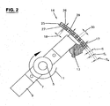
- Fig. 2
- schematisierte vergrösserte Darstellung der Wechselwirkung zwischen Schlegel und Sieb;
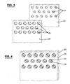
- Fig. 3
- getrennte Darstellung der Komponennten eines Siebs; und
- Fig. 4
- Ausschnitt eines zusammengefügten Siebes.
- Fig. 1
- Longitudinal section through a schematic representation of a hammer mill with a novel sieve;
- Fig. 2
- schematized enlarged representation of the interaction between flail and sieve;
- Fig. 3
- separate representation of the components of a sieve; and
- Fig. 4
- Section of a assembled sieve.
Eine Hammermühle 1 (
An der Welle 5 sind in Lagerböcken 7 die Schlegel 9 drehbeweglich gehalten. Bei Drehung der Welle 5 (Pfeil 11) werden die Schlegel 9 durch die Zentrifugalkraft in eine näherungsweise radiale Ausrichtung gedrängt, wodurch sie die Rohmaterialstücke 13 an die Mantelfläche 15 mit Sieb 16 des Gehäuses 3 andrücken und über diese hinwegschieben (s.
Das Gehäuse 3 ist im Wesentlichen ein Kreiszylinder und umfasst prinzipiell eine kreiszylindrische Wand oder Mantelfläche 15 und zwei Abschlussplatten 19, 21. An geeigneter Stelle, zum Beispiel nah der Abschlussplatte 19, befindet sich eine Vorkehrung wie zum Beispiel ein Zufuhrtrichter (nicht dargestellt) für das Zuführen von Rohmaterial. Entsprechend befindet sich bei oder innerhalb der zweiten Abschlussplatte 21 eine Vorkehrung wie eine Ausgabeöffnung für Bestandteile des Rohmaterials, die in der Hammermühle 1 nicht genügend zerkleinert werden konnten, insbesondere also auch die Störstoffe. Es sind weitere Vorkehrungen getroffen, wie zum Beispiel eine Schrägstellung des Gehäuses 3 oder eine Schrägstellung der Schlegel 9, so dass sich das Rohmaterial in der Hammermühle 1 von der Platte 19 zur Platte 21 bewegt.The
Die Zylinderwand 15 besteht zu einem grossen Teil oder auch insgesamt aus dem Sieb 16, das sich aus einem Innenmantel 25 und einem Aussenmantel 26 zusammensetzt. Innenmantel 25 weist Innenmantelbohrungen 27 auf, die fluchtend mit entsprechenden Aussenmantelbohrungen 29 angeordnet sind. Innenmantel 25 und Aussenmantel 26 weisen auch eine übereinstimmende Lochteilung auf. Die Innenmantelbohrungen sind bestimmend für die Trennwirkung und sind daher mit dem Sieblochdurchmesser 18 ausgeführt. Der hauptsächlich vom Verschleiss betroffene Innenmantel 25 ist aus einem verschleissfesten Stahl gefertigt, der sich durch eine hohe Festigkeit auszeichnet. Dieser Stahl zeichnet sich beispielsweise durch folgenden Festigkeitsparameter aus: Der Rm-Wert beträgt mindestens 600 und bevorzugt mindestens 1000. (Rm: Dehnfestigkeit in Newton pro Quadatratmillimeter [N/mm2] nach ISO-Norm).The
Für den Aussenmantel 26 genügt dagegen ein Stahl mittlerer Festigkeit, zum Beispiel mit einem Rm-Wert von mindestens 340 N/mm2 der jedoch mindestens 400 N/mm2 kleiner als der Rm des Innenmantels 25 ist. Bevorzugt sind Rm-Werte von 340 N/mm2 bis 590 N/mm2 und insbesondere bevorzugt von 490 N/mm2 bis 590 N/mm2.For the
Die Dicken von Innenmantel 25 und Aussenmantel 26 sind annähernd identisch, zum Beispiel mit einer Abweichung von höchstens 50 % des jeweils dickeren Teils. Bevorzugt weisen sie jedoch nominell die gleiche Dicke auf. Aussenmantel 26 und Innenmantel 25 sind durch eine der gängigen Verbindungsarten wie Schweissen zusammengefügt. Dadurch ergibt sich die benötigte Festigkeit und Formbeständigkeit, um als Sieb Verwendung zu finden.The thicknesses of
Siebe konventioneller, einschichtiger Bauart müssen eine Stärke von etwa zweimal S (S: Dicke von Innenmantel [Si] bzw. Aussenmantel [Sa]) aufweisen, um die benötigte Festigkeit und Formbeständigkeit zu erreichen. Um die Bearbeitbarkeit und Verformbarkeit von so starkem Material wie für die vorliegende Anwendung benötigt sicherzustellen, können bei konventioneller, einschichtiger Bauweise nur Stähle mit relativ niedrigen Festigkeitswerten verwendet werden. Im praktischen Einsatz resultieren daraus kurze Standzeiten. Ausserdem ist das Herstellen der Siebbohrungen in starkwandigem Material erschwert und benötigt mehr Zeit.Sieves of conventional, single-layered construction must have a thickness of approximately twice S (S: thickness of inner sheath [Si] or outer sheath [S a ]) in order to achieve the required strength and dimensional stability. In order to ensure the machinability and ductility of material as strong as required for the present application, in conventional, single-layered construction only steels with relatively low strength values can be used. In practical use, this results in short service lives. In addition, making the screen bores in thick-walled material is more difficult and requires more time.
Die heutzutage bevorzugte Art, derartige Bohrungen herzustellen, ist Laserbohren. Bevorzugt sind dabei zylindrische Löcher. In starkwandigem Material sind die erforderlichen kleinen Bohrungen jedoch relativ zu ihrem Durchmesser lang und hemmen damit den Materialfluss. In der vorliegenden Anwendung besteht darüber hinaus ein hohes Verstopfungsrisiko. Konisches Ausweiten von aussen, um diese Effekte zu unterdrücken, ist bei der grossen Anzahl nötigen Bohrungen nicht realistisch.The currently preferred way to make such holes is laser drilling. Preferred are cylindrical holes. In thick-walled material are the required small holes but relative to their diameter long and thus inhibit the flow of material. In addition, there is a high risk of blockage in the present application. Conical expansion from the outside to suppress these effects is not realistic given the large number of holes required.
Bei dem Sieb gemäss vorliegender Erfindung werden die Löcher dagegen separat in Aussenmantel 26 und Innenmantel 25 hergestellt. Zum einen werden die Löcher daher in relativ dünnes Material (Dicke Si bzw. Sa) gebohrt, was mit geringerem Zeitaufwand möglich ist. Im Innenmantel 25 können die Bohrungen 27 ohne weiteres mit dem kleineren Durchmesser 18 als derjenige 30 der Bohrungen 29 im Aussenmantel 26 hergestellt werden (Siehe
Ausserdem wird trotz der kleineren Lochdurchmesser die eingangs genannte Regel eingehalten, dass der Lochdurchmesser die Blechdicke nicht unterschreiten darf. Damit sind Durchmesser der Löcher 27 im Innenmantel 25 möglich, die beispielsweise nur höchstens 80 % der Gesamtmaterialdicke Si + Sa oder auch höchstens 60 % davon betragen oder insbesondere auch etwa gleich der Dicke nur des Innenmantels 25 sind, wobei zur Verbesserung der Trennwirkung kleinere Lochdurchmesser bevorzugt sind.In addition, despite the smaller hole diameter, the rule mentioned above, that the hole diameter must not fall below the plate thickness. Thus, diameters of the
Die Bohrungen 27, 29 werden bevorzugt durch Laserbohren hergestellt. Andere Arten wie mechanisches Bohren oder Stanzen sind auch denkbar, benötigen aber mehr Zeit und sind kosteninteniver.The
Das Material für den Aussenmantel 26 ist ein Stahl einer Qualität, die gut verarbeitet werden kann und biegbar ist. Für den Innenmantel 25 wird ein Stahl mit einem hohen Verschleisswiderstand eingesetzt, der deswegen nur als dünnwandiges Material verformbar und verarbeitbar ist. Nach Zusammenfügen des Aussenmantels 26 mit dem Innenmantel 25, wobei die Löcher fluchtend aufeinander angeordnet werden, was bedingt, dass die Locheinteilungen von Aussenmantel 26 und Innenmantel 25 übereinstimmen, ergibt sich ein Sieb 16 von der benötigten Verschleissfestigkeit und Formbeständigkeit. Bevorzugt erfolgt die Verbindung der Mäntel durch Schweissverbindungen.The material for the
Geschweisst wird dabei punktweise am Rand des Siebs und insbesondere durchgehend an den Stirnseiten, die an den Anschlussplatten anliegen. Stellt das Sieb den ganzen Zylindermantel 15 dar, wird es entsprechend am Stoss der axial aneianderstossenden, axial verlaufenden Kanten ebenfalls geschweisst.Welding is pointwise at the edge of the screen and in particular continuously at the end faces, which rest against the connection plates. If the sieve represents the
Das Sieb weist ein Verhältnis von Lochfläche zu Gesamtfläche von mindestens 30 % auf. Eine andere Masszahl ist, dass der Abstand zwischen zwei Löchern mindestens 60 % des Durchmessers 18 eines Lochs beträgt.The sieve has a ratio of hole area to total area of at least 30%. Another measure is that the distance between two holes is at least 60% of the
Aufgrund der vorangehenden Beschreibung sind dem Fachmann Abwandlungen und Ergänzungen zugänglich, ohne den Schutzbereich der Erfindung zu verlassen, der durch die Ansprüche festgelegt wird. Insbesondere denkbar sind:
- Verwendung von drei oder mehr Mänteln, die zu einem Sieb zusammengefügt sind.
- Die
Bohrungen im Innenmantel 27 weisen einen Durchmesser von höchstens 10 mm auf, bevorzugt von höchstens 6 mm. Denkbar sind auch kleinere Durchmesser je nach Material, das bearbeitet wird, und je nach den Anforderungen an den maximalen Gehalt an Störstoffen. - Innen- und Aussenmantel sind sind durch andere Verbindungsarten wie bspw. Schrauben, Nieten oder Kleben verbunden, gegebenfalls auch durch Kombinationen dieser Verbindungsarten untereinander und mit Schweissen.
- Das Sieb weist für andere Einsatzarten, z.B. als Rüttelsieb, generell eine andere Form auf, z.B. flach. Im flachen Zustand ist zwar der Vorteil, mit verringertem Aufwand ein Sieb von gebogener Form herzustellen, ohne Bedeutung, jedoch bleibt der Vorteil, mit geringerem Aufwand ein Sieb von erhöhter Trennwirkung und Verschleissfestigkeit und geringerer Verstopfungsgefahr herstellen zu können.
- Die Löcher, insbesondere die des Innenmantels, können verschiedene Durchmesser aufweisen, z.B. in axialer Richtung abnehmend, z.B. um die Trennwirkung an die in Wanderungsrichtung des Rohmaterials generell abnehmende Teilchengrösse anzupassen, oder gleichmässig verteilt zur generellen Modifikation der Trennwirkung.
- Der Anteil der gesamten Lochfläche kann anders gewählt werden, z. B. kleiner sein, wodurch die Stabilität des Siebs vergrössert wird, oder auch grösser für höheren Durchsatz, wenn die Anforderungen an die Stabilität geringer sind. Ein denkbarer Lochflächenanteil in
diesem Sinne ist 25 % bis 50 %
- Use of three or more coats assembled into a sieve.
- The holes in the
inner shell 27 have a diameter of at most 10 mm, preferably of at most 6 mm. Also conceivable are smaller diameters depending on the material that is processed, and depending on the requirements for the maximum content of impurities. - Inner and outer sheath are connected by other types of connection such as screws, rivets or gluing, if necessary, also by combinations of these types of connection with each other and with welding.
- The screen has for other types of applications, such as vibrating screen, generally a different shape, eg flat. In the flat state, although the advantage of producing a sieve of curved shape with reduced effort, without meaning, but the advantage remains, with less effort to produce a sieve of increased separation efficiency and wear resistance and less risk of clogging.
- The holes, in particular those of the inner shell, may have different diameters, for example decreasing in the axial direction, for example in order to adapt the separation effect to the particle size generally decreasing in the direction of migration of the raw material, or evenly distributed for the general modification of the separating effect.
- The proportion of the total hole area can be chosen differently, for. B. smaller, which increases the stability of the screen, or even greater for higher throughput, when the requirements for stability are lower. A conceivable hole area proportion in this sense is 25% to 50%
Claims (12)
- Screen (16) for a waste separation device (1), more particularly a hammer mill, characterised in that it comprises at least an inner screen plate (25) of a metal of higher strength and an outer screen plate (26) of lower strength whose hole pitches coincide and which are joined to form a metal composite so that the screen can be provided with smaller holes (27).
- Screen (16) according to claim 1, characterised in that the inner screen plate (25) has holes (27) whose diameter (18) is preferably 5 to 15 % smaller than the diameter (30) of the respective aligned holes (29) in the outer screen plate (26) in order to reduce the passage resistance of the holes.
- Screen (16) according to one of claims 1 or 2, characterised in that the inner screen plate (25) is made of a highly wear-resistant steel.
- Screen (16) according to one of claims 1 to 3, characterised in that the outer screen plate (29) is made of a steel of medium strength.
- Screen (16) according to one of claims 1 to 4, characterised in that the diameter (18) of the holes (27) in the inner screen plate (25) is at most 10 mm, preferably at most 6 mm.
- Screen (16) according to one of claims 1 to 5, characterised in that the entire cross-sectional area of the holes (27) in the inner screen plate (25) amounts to at least 30 %, preferably at least 35 % of the total surface area of the inner screen plate (25).
- Screen (16) according to one of claims 1 to 5, characterised in that the entire cross-sectional area of the holes (27) in the inner screen plate (25) amounts to 25 % to 50 % of the total surface area of the inner screen plate (25).
- Screen (16) according to one of claims 1 to 7, characterised in that the distance between the holes (27) of the inner screen plate (25) is at most equal to the thickness (S) of the metal composite of the screen.
- Screen (16) according to one of claims 1 to 8, characterised in that the inner and outer screen plates (25, 26) are connected to each other by an inseparable connection, preferably by at least one of welding, screwing, riveting, and bonding.
- Screen (16) according to claim 9, characterised in that the connection is made on the entire surface area, in the form of regularly arranged punctual connections, and/or provided at the edge, the latter connection being partly continuous and/or punctual.
- Screen (16) according to one of claims 1 to 10, characterised in that the screen is curved, the outer screen plate (26) being arranged radially outside the inner screen plate (25) and the mean curvature radius preferably being at most equal to 35 % of the largest distance between two edges of the screen.
- Screen (16) according to one of claims 1 to 11, characterised in that the diameter of the holes in the inner screen plate (25) is smaller than the thickness S of the metal composite, preferably at most 80 % and more preferably at most 60 % of the thickness of the metal composite and most preferably substantially equal to the thickness (Si) of the inner screen plate (25).
Applications Claiming Priority (1)
| Application Number | Priority Date | Filing Date | Title |
|---|---|---|---|
| CH5872012A CH706451A2 (en) | 2012-04-27 | 2012-04-27 | Strainer made of composite metal. |
Publications (2)
| Publication Number | Publication Date |
|---|---|
| EP2656919A1 EP2656919A1 (en) | 2013-10-30 |
| EP2656919B1 true EP2656919B1 (en) | 2015-07-01 |
Family
ID=48444049
Family Applications (1)
| Application Number | Title | Priority Date | Filing Date |
|---|---|---|---|
| EP13165572.2A Active EP2656919B1 (en) | 2012-04-27 | 2013-04-26 | Filter for a waste separation apparatus |
Country Status (2)
| Country | Link |
|---|---|
| EP (1) | EP2656919B1 (en) |
| CH (1) | CH706451A2 (en) |
Cited By (1)
| Publication number | Priority date | Publication date | Assignee | Title |
|---|---|---|---|---|
| WO2022171277A1 (en) | 2021-02-10 | 2022-08-18 | Ardey Goetz | Separator, in particular for separating organic waste and additives |
Family Cites Families (4)
| Publication number | Priority date | Publication date | Assignee | Title |
|---|---|---|---|---|
| US1847193A (en) * | 1930-10-18 | 1932-03-01 | Louis D Peters | Adjustable mill screen |
| US3617007A (en) * | 1969-10-03 | 1971-11-02 | Joseph F Bonarrigo Jr | Grate bar assembly for a rock crusher |
| JP3947913B2 (en) * | 2002-02-19 | 2007-07-25 | 株式会社サタケ | Grain impact crusher |
| EP1350569B1 (en) | 2002-04-03 | 2014-06-25 | Anton Berger | Waste separation apparatus |
-
2012
- 2012-04-27 CH CH5872012A patent/CH706451A2/en not_active Application Discontinuation
-
2013
- 2013-04-26 EP EP13165572.2A patent/EP2656919B1/en active Active
Cited By (1)
| Publication number | Priority date | Publication date | Assignee | Title |
|---|---|---|---|---|
| WO2022171277A1 (en) | 2021-02-10 | 2022-08-18 | Ardey Goetz | Separator, in particular for separating organic waste and additives |
Also Published As
| Publication number | Publication date |
|---|---|
| EP2656919A1 (en) | 2013-10-30 |
| CH706451A2 (en) | 2013-10-31 |
Similar Documents
| Publication | Publication Date | Title |
|---|---|---|
| DE2513853C2 (en) | Device for shredding and sorting municipal waste | |
| EP2155353B1 (en) | Press screw separator | |
| EP3626350A2 (en) | Agitator ball mill and method for operating same | |
| WO2009024158A1 (en) | Stirrer mill | |
| WO2004112973A2 (en) | Drum sieve machine | |
| DE102010053484A1 (en) | Dynamic element for the separator of a stirred ball mill | |
| EP1909976B1 (en) | Screening device | |
| EP2178643B1 (en) | Stirrer mill | |
| EP2065092A2 (en) | Device and method of releasing the composite of a feeder product in a composite | |
| WO2014012693A2 (en) | Comminution of grinding stock in a vertical roller mill | |
| DE102011088102A1 (en) | Sieve for sifting a pulp suspension | |
| DE102011000018A1 (en) | More roll crusher | |
| EP2656919B1 (en) | Filter for a waste separation apparatus | |
| DE102005039200B4 (en) | Crushing device with a plurality of substantially parallel, motor-driven, rotating or oscillating waves | |
| EP1826315B1 (en) | Rotor for pressure screen for fibrous suspensions | |
| DE102017103844A1 (en) | Device for processing materials | |
| DE3342812A1 (en) | DEVICE AND METHOD FOR THE EXTRUSION OF CELLULOSE-CONTAINING SUBSTANCES | |
| WO2017133720A1 (en) | Comminuting machine comprising a feed chute and method for feeding material into a comminuting machine | |
| DE102006006703A1 (en) | Treatment of contaminated waste residue from recycled paper pulping involves continuous grinding in a hammer mill with simultaneous centrifugal fiber removal through a sieve | |
| EP1059381B1 (en) | Rotor for a pulper | |
| EP2602386A1 (en) | Screen device | |
| EP1448303B1 (en) | Tube grinder and method for comminuting lumpy grinding stock | |
| DE202021104919U1 (en) | Device for separating liquid and solid material from each other | |
| EP2823702B1 (en) | Fine crushing device | |
| DE3041270C2 (en) | Grinding sieve, especially for hammer mills |
Legal Events
| Date | Code | Title | Description |
|---|---|---|---|
| PUAI | Public reference made under article 153(3) epc to a published international application that has entered the european phase |
Free format text: ORIGINAL CODE: 0009012 |
|
| AK | Designated contracting states |
Kind code of ref document: A1 Designated state(s): AL AT BE BG CH CY CZ DE DK EE ES FI FR GB GR HR HU IE IS IT LI LT LU LV MC MK MT NL NO PL PT RO RS SE SI SK SM TR |
|
| AX | Request for extension of the european patent |
Extension state: BA ME |
|
| 17P | Request for examination filed |
Effective date: 20140430 |
|
| RBV | Designated contracting states (corrected) |
Designated state(s): AL AT BE BG CH CY CZ DE DK EE ES FI FR GB GR HR HU IE IS IT LI LT LU LV MC MK MT NL NO PL PT RO RS SE SI SK SM TR |
|
| GRAP | Despatch of communication of intention to grant a patent |
Free format text: ORIGINAL CODE: EPIDOSNIGR1 |
|
| GRAJ | Information related to disapproval of communication of intention to grant by the applicant or resumption of examination proceedings by the epo deleted |
Free format text: ORIGINAL CODE: EPIDOSDIGR1 |
|
| GRAP | Despatch of communication of intention to grant a patent |
Free format text: ORIGINAL CODE: EPIDOSNIGR1 |
|
| INTG | Intention to grant announced |
Effective date: 20140909 |
|
| GRAP | Despatch of communication of intention to grant a patent |
Free format text: ORIGINAL CODE: EPIDOSNIGR1 |
|
| GRAJ | Information related to disapproval of communication of intention to grant by the applicant or resumption of examination proceedings by the epo deleted |
Free format text: ORIGINAL CODE: EPIDOSDIGR1 |
|
| GRAP | Despatch of communication of intention to grant a patent |
Free format text: ORIGINAL CODE: EPIDOSNIGR1 |
|
| INTG | Intention to grant announced |
Effective date: 20150129 |
|
| INTG | Intention to grant announced |
Effective date: 20150210 |
|
| GRAS | Grant fee paid |
Free format text: ORIGINAL CODE: EPIDOSNIGR3 |
|
| GRAA | (expected) grant |
Free format text: ORIGINAL CODE: 0009210 |
|
| AK | Designated contracting states |
Kind code of ref document: B1 Designated state(s): AL AT BE BG CH CY CZ DE DK EE ES FI FR GB GR HR HU IE IS IT LI LT LU LV MC MK MT NL NO PL PT RO RS SE SI SK SM TR |
|
| REG | Reference to a national code |
Ref country code: GB Ref legal event code: FG4D Free format text: NOT ENGLISH |
|
| REG | Reference to a national code |
Ref country code: AT Ref legal event code: REF Ref document number: 733624 Country of ref document: AT Kind code of ref document: T Effective date: 20150715 Ref country code: CH Ref legal event code: EP |
|
| REG | Reference to a national code |
Ref country code: IE Ref legal event code: FG4D Free format text: LANGUAGE OF EP DOCUMENT: GERMAN |
|
| REG | Reference to a national code |
Ref country code: DE Ref legal event code: R096 Ref document number: 502013000796 Country of ref document: DE |
|
| REG | Reference to a national code |
Ref country code: CH Ref legal event code: NV Representative=s name: AMMANN PATENTANWAELTE AG BERN, CH |
|
| REG | Reference to a national code |
Ref country code: NL Ref legal event code: MP Effective date: 20150701 |
|
| REG | Reference to a national code |
Ref country code: LT Ref legal event code: MG4D |
|
| PG25 | Lapsed in a contracting state [announced via postgrant information from national office to epo] |
Ref country code: NO Free format text: LAPSE BECAUSE OF FAILURE TO SUBMIT A TRANSLATION OF THE DESCRIPTION OR TO PAY THE FEE WITHIN THE PRESCRIBED TIME-LIMIT Effective date: 20151001 Ref country code: FI Free format text: LAPSE BECAUSE OF FAILURE TO SUBMIT A TRANSLATION OF THE DESCRIPTION OR TO PAY THE FEE WITHIN THE PRESCRIBED TIME-LIMIT Effective date: 20150701 Ref country code: LT Free format text: LAPSE BECAUSE OF FAILURE TO SUBMIT A TRANSLATION OF THE DESCRIPTION OR TO PAY THE FEE WITHIN THE PRESCRIBED TIME-LIMIT Effective date: 20150701 Ref country code: LV Free format text: LAPSE BECAUSE OF FAILURE TO SUBMIT A TRANSLATION OF THE DESCRIPTION OR TO PAY THE FEE WITHIN THE PRESCRIBED TIME-LIMIT Effective date: 20150701 Ref country code: GR Free format text: LAPSE BECAUSE OF FAILURE TO SUBMIT A TRANSLATION OF THE DESCRIPTION OR TO PAY THE FEE WITHIN THE PRESCRIBED TIME-LIMIT Effective date: 20151002 |
|
| PG25 | Lapsed in a contracting state [announced via postgrant information from national office to epo] |
Ref country code: PT Free format text: LAPSE BECAUSE OF FAILURE TO SUBMIT A TRANSLATION OF THE DESCRIPTION OR TO PAY THE FEE WITHIN THE PRESCRIBED TIME-LIMIT Effective date: 20151102 Ref country code: PL Free format text: LAPSE BECAUSE OF FAILURE TO SUBMIT A TRANSLATION OF THE DESCRIPTION OR TO PAY THE FEE WITHIN THE PRESCRIBED TIME-LIMIT Effective date: 20150701 Ref country code: ES Free format text: LAPSE BECAUSE OF FAILURE TO SUBMIT A TRANSLATION OF THE DESCRIPTION OR TO PAY THE FEE WITHIN THE PRESCRIBED TIME-LIMIT Effective date: 20150701 Ref country code: HR Free format text: LAPSE BECAUSE OF FAILURE TO SUBMIT A TRANSLATION OF THE DESCRIPTION OR TO PAY THE FEE WITHIN THE PRESCRIBED TIME-LIMIT Effective date: 20150701 Ref country code: RS Free format text: LAPSE BECAUSE OF FAILURE TO SUBMIT A TRANSLATION OF THE DESCRIPTION OR TO PAY THE FEE WITHIN THE PRESCRIBED TIME-LIMIT Effective date: 20150701 Ref country code: IS Free format text: LAPSE BECAUSE OF FAILURE TO SUBMIT A TRANSLATION OF THE DESCRIPTION OR TO PAY THE FEE WITHIN THE PRESCRIBED TIME-LIMIT Effective date: 20151101 Ref country code: SE Free format text: LAPSE BECAUSE OF FAILURE TO SUBMIT A TRANSLATION OF THE DESCRIPTION OR TO PAY THE FEE WITHIN THE PRESCRIBED TIME-LIMIT Effective date: 20150701 |
|
| REG | Reference to a national code |
Ref country code: DE Ref legal event code: R097 Ref document number: 502013000796 Country of ref document: DE |
|
| PG25 | Lapsed in a contracting state [announced via postgrant information from national office to epo] |
Ref country code: CZ Free format text: LAPSE BECAUSE OF FAILURE TO SUBMIT A TRANSLATION OF THE DESCRIPTION OR TO PAY THE FEE WITHIN THE PRESCRIBED TIME-LIMIT Effective date: 20150701 Ref country code: SK Free format text: LAPSE BECAUSE OF FAILURE TO SUBMIT A TRANSLATION OF THE DESCRIPTION OR TO PAY THE FEE WITHIN THE PRESCRIBED TIME-LIMIT Effective date: 20150701 Ref country code: IT Free format text: LAPSE BECAUSE OF FAILURE TO SUBMIT A TRANSLATION OF THE DESCRIPTION OR TO PAY THE FEE WITHIN THE PRESCRIBED TIME-LIMIT Effective date: 20150701 Ref country code: EE Free format text: LAPSE BECAUSE OF FAILURE TO SUBMIT A TRANSLATION OF THE DESCRIPTION OR TO PAY THE FEE WITHIN THE PRESCRIBED TIME-LIMIT Effective date: 20150701 Ref country code: DK Free format text: LAPSE BECAUSE OF FAILURE TO SUBMIT A TRANSLATION OF THE DESCRIPTION OR TO PAY THE FEE WITHIN THE PRESCRIBED TIME-LIMIT Effective date: 20150701 |
|
| PLBE | No opposition filed within time limit |
Free format text: ORIGINAL CODE: 0009261 |
|
| STAA | Information on the status of an ep patent application or granted ep patent |
Free format text: STATUS: NO OPPOSITION FILED WITHIN TIME LIMIT |
|
| PG25 | Lapsed in a contracting state [announced via postgrant information from national office to epo] |
Ref country code: RO Free format text: LAPSE BECAUSE OF FAILURE TO SUBMIT A TRANSLATION OF THE DESCRIPTION OR TO PAY THE FEE WITHIN THE PRESCRIBED TIME-LIMIT Effective date: 20150701 |
|
| 26N | No opposition filed |
Effective date: 20160404 |
|
| PG25 | Lapsed in a contracting state [announced via postgrant information from national office to epo] |
Ref country code: SI Free format text: LAPSE BECAUSE OF FAILURE TO SUBMIT A TRANSLATION OF THE DESCRIPTION OR TO PAY THE FEE WITHIN THE PRESCRIBED TIME-LIMIT Effective date: 20150701 Ref country code: BE Free format text: LAPSE BECAUSE OF NON-PAYMENT OF DUE FEES Effective date: 20160430 |
|
| REG | Reference to a national code |
Ref country code: DE Ref legal event code: R119 Ref document number: 502013000796 Country of ref document: DE |
|
| PG25 | Lapsed in a contracting state [announced via postgrant information from national office to epo] |
Ref country code: LU Free format text: LAPSE BECAUSE OF FAILURE TO SUBMIT A TRANSLATION OF THE DESCRIPTION OR TO PAY THE FEE WITHIN THE PRESCRIBED TIME-LIMIT Effective date: 20160426 |
|
| REG | Reference to a national code |
Ref country code: IE Ref legal event code: MM4A |
|
| REG | Reference to a national code |
Ref country code: FR Ref legal event code: ST Effective date: 20161230 |
|
| PG25 | Lapsed in a contracting state [announced via postgrant information from national office to epo] |
Ref country code: DE Free format text: LAPSE BECAUSE OF NON-PAYMENT OF DUE FEES Effective date: 20161101 Ref country code: FR Free format text: LAPSE BECAUSE OF NON-PAYMENT OF DUE FEES Effective date: 20160502 |
|
| PG25 | Lapsed in a contracting state [announced via postgrant information from national office to epo] |
Ref country code: IE Free format text: LAPSE BECAUSE OF NON-PAYMENT OF DUE FEES Effective date: 20160426 |
|
| PG25 | Lapsed in a contracting state [announced via postgrant information from national office to epo] |
Ref country code: NL Free format text: LAPSE BECAUSE OF FAILURE TO SUBMIT A TRANSLATION OF THE DESCRIPTION OR TO PAY THE FEE WITHIN THE PRESCRIBED TIME-LIMIT Effective date: 20150701 |
|
| GBPC | Gb: european patent ceased through non-payment of renewal fee |
Effective date: 20170426 |
|
| PG25 | Lapsed in a contracting state [announced via postgrant information from national office to epo] |
Ref country code: GB Free format text: LAPSE BECAUSE OF NON-PAYMENT OF DUE FEES Effective date: 20170426 |
|
| PG25 | Lapsed in a contracting state [announced via postgrant information from national office to epo] |
Ref country code: CY Free format text: LAPSE BECAUSE OF FAILURE TO SUBMIT A TRANSLATION OF THE DESCRIPTION OR TO PAY THE FEE WITHIN THE PRESCRIBED TIME-LIMIT Effective date: 20150701 Ref country code: SM Free format text: LAPSE BECAUSE OF FAILURE TO SUBMIT A TRANSLATION OF THE DESCRIPTION OR TO PAY THE FEE WITHIN THE PRESCRIBED TIME-LIMIT Effective date: 20150701 Ref country code: HU Free format text: LAPSE BECAUSE OF FAILURE TO SUBMIT A TRANSLATION OF THE DESCRIPTION OR TO PAY THE FEE WITHIN THE PRESCRIBED TIME-LIMIT; INVALID AB INITIO Effective date: 20130426 |
|
| PG25 | Lapsed in a contracting state [announced via postgrant information from national office to epo] |
Ref country code: MK Free format text: LAPSE BECAUSE OF FAILURE TO SUBMIT A TRANSLATION OF THE DESCRIPTION OR TO PAY THE FEE WITHIN THE PRESCRIBED TIME-LIMIT Effective date: 20150701 Ref country code: MC Free format text: LAPSE BECAUSE OF FAILURE TO SUBMIT A TRANSLATION OF THE DESCRIPTION OR TO PAY THE FEE WITHIN THE PRESCRIBED TIME-LIMIT Effective date: 20150701 Ref country code: TR Free format text: LAPSE BECAUSE OF FAILURE TO SUBMIT A TRANSLATION OF THE DESCRIPTION OR TO PAY THE FEE WITHIN THE PRESCRIBED TIME-LIMIT Effective date: 20150701 Ref country code: MT Free format text: LAPSE BECAUSE OF FAILURE TO SUBMIT A TRANSLATION OF THE DESCRIPTION OR TO PAY THE FEE WITHIN THE PRESCRIBED TIME-LIMIT Effective date: 20150701 |
|
| PG25 | Lapsed in a contracting state [announced via postgrant information from national office to epo] |
Ref country code: BG Free format text: LAPSE BECAUSE OF FAILURE TO SUBMIT A TRANSLATION OF THE DESCRIPTION OR TO PAY THE FEE WITHIN THE PRESCRIBED TIME-LIMIT Effective date: 20150701 |
|
| PG25 | Lapsed in a contracting state [announced via postgrant information from national office to epo] |
Ref country code: AL Free format text: LAPSE BECAUSE OF FAILURE TO SUBMIT A TRANSLATION OF THE DESCRIPTION OR TO PAY THE FEE WITHIN THE PRESCRIBED TIME-LIMIT Effective date: 20150701 |
|
| REG | Reference to a national code |
Ref country code: CH Ref legal event code: PL |
|
| REG | Reference to a national code |
Ref country code: CH Ref legal event code: AECN Free format text: DAS PATENT WURDE AUFGRUND DES WEITERBEHANDLUNGSANTRAGS VOM 03.01.2019 REAKTIVIERT. |
|
| PG25 | Lapsed in a contracting state [announced via postgrant information from national office to epo] |
Ref country code: LI Free format text: LAPSE BECAUSE OF NON-PAYMENT OF DUE FEES Effective date: 20180430 Ref country code: CH Free format text: LAPSE BECAUSE OF NON-PAYMENT OF DUE FEES Effective date: 20180430 |
|
| PGRI | Patent reinstated in contracting state [announced from national office to epo] |
Ref country code: CH Effective date: 20190104 Ref country code: LI Effective date: 20190104 |
|
| REG | Reference to a national code |
Ref country code: AT Ref legal event code: MM01 Ref document number: 733624 Country of ref document: AT Kind code of ref document: T Effective date: 20180426 |
|
| PG25 | Lapsed in a contracting state [announced via postgrant information from national office to epo] |
Ref country code: AT Free format text: LAPSE BECAUSE OF NON-PAYMENT OF DUE FEES Effective date: 20180426 |
|
| PGFP | Annual fee paid to national office [announced via postgrant information from national office to epo] |
Ref country code: CH Payment date: 20230502 Year of fee payment: 11 |