EP2656741A2 - Method and device for cooling products - Google Patents
Method and device for cooling products Download PDFInfo
- Publication number
- EP2656741A2 EP2656741A2 EP13163560.9A EP13163560A EP2656741A2 EP 2656741 A2 EP2656741 A2 EP 2656741A2 EP 13163560 A EP13163560 A EP 13163560A EP 2656741 A2 EP2656741 A2 EP 2656741A2
- Authority
- EP
- European Patent Office
- Prior art keywords
- carbon dioxide
- gas
- cold gas
- cooling
- stream
- Prior art date
- Legal status (The legal status is an assumption and is not a legal conclusion. Google has not performed a legal analysis and makes no representation as to the accuracy of the status listed.)
- Granted
Links
- 238000001816 cooling Methods 0.000 title claims abstract description 42
- 238000000034 method Methods 0.000 title claims abstract description 15
- CURLTUGMZLYLDI-UHFFFAOYSA-N Carbon dioxide Chemical compound O=C=O CURLTUGMZLYLDI-UHFFFAOYSA-N 0.000 claims abstract description 316
- 229910002092 carbon dioxide Inorganic materials 0.000 claims abstract description 156
- 239000001569 carbon dioxide Substances 0.000 claims abstract description 156
- 239000002245 particle Substances 0.000 claims abstract description 23
- 239000008246 gaseous mixture Substances 0.000 claims abstract description 4
- 239000007789 gas Substances 0.000 claims description 110
- 239000007788 liquid Substances 0.000 claims description 33
- IJGRMHOSHXDMSA-UHFFFAOYSA-N Atomic nitrogen Chemical compound N#N IJGRMHOSHXDMSA-UHFFFAOYSA-N 0.000 claims description 25
- 239000000203 mixture Substances 0.000 claims description 13
- 229910052757 nitrogen Inorganic materials 0.000 claims description 12
- XKRFYHLGVUSROY-UHFFFAOYSA-N Argon Chemical compound [Ar] XKRFYHLGVUSROY-UHFFFAOYSA-N 0.000 claims description 8
- 229910052786 argon Inorganic materials 0.000 claims description 4
- 239000012530 fluid Substances 0.000 claims description 4
- QVGXLLKOCUKJST-UHFFFAOYSA-N atomic oxygen Chemical compound [O] QVGXLLKOCUKJST-UHFFFAOYSA-N 0.000 claims description 3
- 239000001301 oxygen Substances 0.000 claims description 3
- 229910052760 oxygen Inorganic materials 0.000 claims description 3
- 238000002156 mixing Methods 0.000 abstract description 6
- 239000007787 solid Substances 0.000 description 6
- 238000009835 boiling Methods 0.000 description 4
- 235000011089 carbon dioxide Nutrition 0.000 description 4
- 239000002826 coolant Substances 0.000 description 4
- 238000000859 sublimation Methods 0.000 description 4
- 230000008022 sublimation Effects 0.000 description 4
- 235000013305 food Nutrition 0.000 description 3
- 238000000926 separation method Methods 0.000 description 3
- 239000000126 substance Substances 0.000 description 3
- 239000000725 suspension Substances 0.000 description 3
- 238000005520 cutting process Methods 0.000 description 2
- 230000000694 effects Effects 0.000 description 2
- 239000008188 pellet Substances 0.000 description 2
- 238000004781 supercooling Methods 0.000 description 2
- MVWDJLOUEUAWIE-UHFFFAOYSA-N O=C=O.O=C=O Chemical compound O=C=O.O=C=O MVWDJLOUEUAWIE-UHFFFAOYSA-N 0.000 description 1
- 238000006243 chemical reaction Methods 0.000 description 1
- 238000007796 conventional method Methods 0.000 description 1
- 238000009826 distribution Methods 0.000 description 1
- 239000001307 helium Substances 0.000 description 1
- 229910052734 helium Inorganic materials 0.000 description 1
- SWQJXJOGLNCZEY-UHFFFAOYSA-N helium atom Chemical compound [He] SWQJXJOGLNCZEY-UHFFFAOYSA-N 0.000 description 1
- 230000002631 hypothermal effect Effects 0.000 description 1
- 238000002347 injection Methods 0.000 description 1
- 239000007924 injection Substances 0.000 description 1
- 238000004519 manufacturing process Methods 0.000 description 1
- JCXJVPUVTGWSNB-UHFFFAOYSA-N nitrogen dioxide Inorganic materials O=[N]=O JCXJVPUVTGWSNB-UHFFFAOYSA-N 0.000 description 1
- 229910052756 noble gas Inorganic materials 0.000 description 1
- 231100000956 nontoxicity Toxicity 0.000 description 1
- 238000004064 recycling Methods 0.000 description 1
Images
Classifications
-
- A—HUMAN NECESSITIES
- A23—FOODS OR FOODSTUFFS; TREATMENT THEREOF, NOT COVERED BY OTHER CLASSES
- A23L—FOODS, FOODSTUFFS, OR NON-ALCOHOLIC BEVERAGES, NOT COVERED BY SUBCLASSES A21D OR A23B-A23J; THEIR PREPARATION OR TREATMENT, e.g. COOKING, MODIFICATION OF NUTRITIVE QUALITIES, PHYSICAL TREATMENT; PRESERVATION OF FOODS OR FOODSTUFFS, IN GENERAL
- A23L3/00—Preservation of foods or foodstuffs, in general, e.g. pasteurising, sterilising, specially adapted for foods or foodstuffs
- A23L3/36—Freezing; Subsequent thawing; Cooling
- A23L3/37—Freezing; Subsequent thawing; Cooling with addition of or treatment with chemicals
- A23L3/375—Freezing; Subsequent thawing; Cooling with addition of or treatment with chemicals with direct contact between the food and the chemical, e.g. liquid nitrogen, at cryogenic temperature
-
- F—MECHANICAL ENGINEERING; LIGHTING; HEATING; WEAPONS; BLASTING
- F25—REFRIGERATION OR COOLING; COMBINED HEATING AND REFRIGERATION SYSTEMS; HEAT PUMP SYSTEMS; MANUFACTURE OR STORAGE OF ICE; LIQUEFACTION SOLIDIFICATION OF GASES
- F25B—REFRIGERATION MACHINES, PLANTS OR SYSTEMS; COMBINED HEATING AND REFRIGERATION SYSTEMS; HEAT PUMP SYSTEMS
- F25B9/00—Compression machines, plants or systems, in which the refrigerant is air or other gas of low boiling point
- F25B9/02—Compression machines, plants or systems, in which the refrigerant is air or other gas of low boiling point using Joule-Thompson effect; using vortex effect
- F25B9/04—Compression machines, plants or systems, in which the refrigerant is air or other gas of low boiling point using Joule-Thompson effect; using vortex effect using vortex effect
-
- F—MECHANICAL ENGINEERING; LIGHTING; HEATING; WEAPONS; BLASTING
- F25—REFRIGERATION OR COOLING; COMBINED HEATING AND REFRIGERATION SYSTEMS; HEAT PUMP SYSTEMS; MANUFACTURE OR STORAGE OF ICE; LIQUEFACTION SOLIDIFICATION OF GASES
- F25D—REFRIGERATORS; COLD ROOMS; ICE-BOXES; COOLING OR FREEZING APPARATUS NOT OTHERWISE PROVIDED FOR
- F25D3/00—Devices using other cold materials; Devices using cold-storage bodies
- F25D3/10—Devices using other cold materials; Devices using cold-storage bodies using liquefied gases, e.g. liquid air
-
- F—MECHANICAL ENGINEERING; LIGHTING; HEATING; WEAPONS; BLASTING
- F25—REFRIGERATION OR COOLING; COMBINED HEATING AND REFRIGERATION SYSTEMS; HEAT PUMP SYSTEMS; MANUFACTURE OR STORAGE OF ICE; LIQUEFACTION SOLIDIFICATION OF GASES
- F25D—REFRIGERATORS; COLD ROOMS; ICE-BOXES; COOLING OR FREEZING APPARATUS NOT OTHERWISE PROVIDED FOR
- F25D3/00—Devices using other cold materials; Devices using cold-storage bodies
- F25D3/12—Devices using other cold materials; Devices using cold-storage bodies using solidified gases, e.g. carbon-dioxide snow
Landscapes
- Engineering & Computer Science (AREA)
- Chemical & Material Sciences (AREA)
- Mechanical Engineering (AREA)
- Thermal Sciences (AREA)
- General Engineering & Computer Science (AREA)
- Physics & Mathematics (AREA)
- Combustion & Propulsion (AREA)
- General Chemical & Material Sciences (AREA)
- Chemical Kinetics & Catalysis (AREA)
- Health & Medical Sciences (AREA)
- Life Sciences & Earth Sciences (AREA)
- Food Science & Technology (AREA)
- Polymers & Plastics (AREA)
- Nutrition Science (AREA)
- Carbon And Carbon Compounds (AREA)
- Physical Or Chemical Processes And Apparatus (AREA)
Abstract
Description
Die Erfindung betrifft ein Verfahren zum Kühlen von Produkten, bei dem unter Druck herangeführtes flüssiges Kohlendioxid an einer Kohlendioxid-Entspannungsdüse zu Kohlendioxidgas und Kohledioxidschnee entspannt wird und der Kohlendioxidschnee zum Kühlen eines Produkts eingesetzt wird. Die Erfindung betrifft des Weiteren eine entsprechende Vorrichtung.The invention relates to a method for cooling products, wherein the liquid carbon dioxide introduced under pressure at a carbon dioxide expansion nozzle is expanded to carbon dioxide gas and carbon dioxide snow and the carbon dioxide snow is used for cooling a product. The invention further relates to a corresponding device.
Bei üblichen Einrichtungen zum Erzeugen von Trockeneisteilchen wird flüssiges Kohlendioxid unter einem Druck von 5,18 bar abs. und einer der Umgebungstemperatur entsprechenden Temperatur herangeführt und an einer Düse, der sogenannten Entspannungsdüse, entspannt. Bei der Entspannung auf Atmosphärendruck kühlt sich das Kohlendioxid auf eine Temperatur von -78,9°C (194 K) ab, wobei ein Gemisch aus Kohlendioxidschnee und kaltem Kohlendioxidgas entsteht. Zumindest die Kohlendioxidpartikel werden anschließend zum Kühlen von Produkten eingesetzt und beispielsweise auf die Oberfläche eines zu kühlenden Produkts aufgetragen.In conventional devices for producing Trockeneisteilchen liquid carbon dioxide under a pressure of 5.18 bar abs. and a temperature corresponding to the ambient temperature and relaxed at a nozzle, the so-called expansion nozzle. When depressurized to atmospheric pressure, the carbon dioxide cools to a temperature of -78.9 ° C (194 K), producing a mixture of carbon dioxide snow and cold carbon dioxide gas. At least the carbon dioxide particles are then used to cool products and, for example, applied to the surface of a product to be cooled.
Aufgrund seiner Ungiftigkeit, seiner inerten Eigenschaften und des Umstands, dass es bei Erwärmung rückstandsfrei sublimiert, eignet sich Kohlendioxidschnee insbesondere zum Kühlen von Lebensmittelprodukten. Typische Anwendungen sind beispielsweise:
- Krustieren: Hier wird ein Lebensmittelprodukt nur an der Oberfläche abgekühlt, um beispielsweise eine mechanische Stabilität des Produkts bei einer mechanischen Behandlung, beispielsweise beim Zerteilen oder Schneiden des Produkts zu gewährleisten. Dazu wird Kohlendioxidschnee mittels Schneehörner, die oberhalb des zu kühlenden Produkts angeordnet sind, auf die Oberfläche des Lebensmittelprodukts aufgetragen.
- Kryogene Kühltunnel: Hierbei sind mehrere Entspannungsdüsen für Kohlendioxid in Laufrichtung des Produkts hintereinander angeordnet aus denen ein Gemisch aus Kohlendioxidschnee und Kohlendioxidgas in den Innenraum des Tunnels eingesprüht wird. Ventilatoren innerhalb des Tunnels sorgen dabei für eine möglichst gleichmäßige Verteilung des Kohlendioxidschnees innerhalb des Tunnels.
- Mischerkühlung: Hierbei wird das flüssige oder feste Kühlmedium (flüssiger Stickstoff oder Kohlendioxidpartikel) mittels Injektionsdüsen oder einer anderen Zuführung in einen das Produkt enthaltenden Behälter eingebracht.
- Encrusting: Here, a food product is cooled only at the surface to ensure, for example, a mechanical stability of the product in a mechanical treatment, for example, when cutting or cutting the product. For this purpose, carbon dioxide snow is applied to the surface of the food product by means of snow horns, which are arranged above the product to be cooled.
- Cryogenic Cooling Tunnels: Here, several carbon dioxide expansion nozzles are arranged in succession in the direction of the product from which a mixture of carbon dioxide snow and carbon dioxide gas is sprayed into the interior of the tunnel. Fans inside the tunnel ensure that the carbon dioxide snow within the tunnel is distributed as evenly as possible.
- Mixer cooling: Here, the liquid or solid cooling medium (liquid nitrogen or carbon dioxide particles) is introduced by means of injection nozzles or another feed into a container containing the product.
Die Kühlung mit Kohlendioxid in Form fester Partikel (Kohlendioxidschnee oder Trockeneispellets) ermöglicht eine sehr effektive Fest- Fest Übertragung der Wärme vom Produkt auf das Kühlmedium. Allerdings ist die Kühlrate des Kohlendioxidschnees aufgrund der Temperatur von ca. minus 78,9°C (194 K) begrenzt. Weiterhin ist bei der Entspannung von flüssigem Kohlendioxid, bei dem das flüssige Kohlendioxid in gasförmiges Kohlendioxid und Kohlendioxidschnee übergeht, der Anteil an erzeugtem Kohlendioxidschnee umso höher, je kälter das flüssige Kohlendioxid vor der Entspannung war. Insbesondere bei der Erzeugung von Trockeneispellets wird daher versucht, die Ausbeute an Kohlendioxidschnee dadurch zu erhöhen, dass das flüssige Kohlendioxid vor der Entspannung gekühlt wird.Cooling with carbon dioxide in the form of solid particles (carbon dioxide snow or dry ice pellets) enables a very effective solid-hard transfer of heat from the product to the cooling medium. However, the cooling rate of the carbon dioxide snow is limited due to the temperature of about minus 78.9 ° C (194 K). Furthermore, in the expansion of liquid carbon dioxide, in which the liquid carbon dioxide passes into gaseous carbon dioxide and carbon dioxide snow, the proportion of carbon dioxide snow produced is higher, the colder the liquid carbon dioxide was before the relaxation. In particular, in the production of dry ice pellets is therefore trying to increase the yield of carbon dioxide snow in that the liquid carbon dioxide is cooled before the relaxation.
Da sich der bei der Entspannung von flüssigem Kohlendioxid erzeugte Kohlendioxidschnee bei Wärmeeintrag d.h. im Energieaustausch mit einem wärmeren Produkt entlang der Sublimationskurve bewegt, sublimiert ein Teil des festen Kohlendioxids bereits unmittelbar nach dem Auftragen auf ein zu kühlendes Produkt. Das dabei entstehende gasförmige Kohlendioxid kann, ähnlich dem von siedenden Flüssigkeiten her bekannten Leidenfrost-Effekt, ein Gaspolster zwischen Kohlendioxidschnee und Produkt bilden und dadurch die Effektivität der Kühlung mindern.Since the carbon dioxide snow generated by the expansion of liquid carbon dioxide is absorbed by heat input, i. moved in the exchange of energy with a warmer product along the Sublimationskurve sublimated part of the solid carbon dioxide immediately after application to a product to be cooled. The resulting gaseous carbon dioxide may, similar to the Leidenfrost effect known from boiling liquids ago, form a gas cushion between carbon dioxide snow and product and thereby reduce the effectiveness of the cooling.
Um den vorgenannten Nachteilen der Kühlung mit Kohlendioxidschnee zu begegnen wurden in der
Der Erfindung liegt daher die Aufgabe zu Grunde, ein Verfahren und eine Vorrichtung zum Kühlen von Produkten zu schaffen, bei dem bzw. bei der die Probleme, die bei flüssigen kryogenen Kühlmedien auftreten, überwunden werden und gleichzeitig die Effizienz der Kühlung gegenüber den aus dem Stand der Technik bekannten Verfahren erhöht werden kann.The invention is therefore based on the object to provide a method and an apparatus for cooling of products, in which or in which the problems that occur in liquid cryogenic cooling media are overcome and at the same time the efficiency of the cooling compared to those from the state The technique known in the art can be increased.
Gelöst ist diese Aufgabe durch ein Verfahren mit Merkmalen des Patentanspruchs 1 sowie durch eine Vorrichtung mit den Merkmalen des Patentanspruchs 5.This object is achieved by a method having features of patent claim 1 and by a device having the features of
Das erfindungsgemäße Verfahren zum Kühlen von Produkten, bei dem unter Druck herangeführtes flüssiges Kohlendioxid an einer Kohlendioxid-Entspannungsdüse zu Kohlendioxidgas und Kohledioxidschnee entspannt und der Kohlendioxidschnee zum Kühlen eines Produkts eingesetzt wird, ist also dadurch gekennzeichnet, dass der aus der Kohlendioxid-Entspannungsdüse austretende Strom aus Kohlendioxidschnee und Kohlendioxidgas in einer Kühl- und Trenneinrichtung mit einem aus einer Kaltgas-Austrittsdüse austretenden Strom eines Kaltgases durchmischt und dabei unterkühlt wird und anschließend die Kohlendioxidteilchen von dem gasförmigem Gemisch aus Kohlendioxidgas und Kaltgas zumindest teilweise getrennt werden. In der Kühl- und Trenneinrichtung erfolgt aufgrund der innigen Durchmischung des Gemisches aus Kohlendioxidgas und Kohledioxidschnee mit dem Kaltgas somit zum einen eine wirksame Unterkühlung der Trockeneisteilchen, zum anderen eine zumindest weitgehende Trennung der unterkühlten Trockeneisteilchen vom Gasstrom.The inventive method for cooling of products, in which brought under pressure liquid carbon dioxide at a carbon dioxide expansion nozzle to carbon dioxide gas and carbon dioxide snow and the carbon dioxide snow is used to cool a product is thus characterized in that the emerging from the carbon dioxide expansion nozzle stream from Carbon dioxide snow and carbon dioxide gas mixed in a cooling and separating device with an emerging from a cold gas outlet nozzle stream of cold gas and is undercooled and then the carbon dioxide particles are at least partially separated from the gaseous mixture of carbon dioxide gas and cold gas. In the cooling and separating device is due to the intimate mixing of the mixture of carbon dioxide gas and carbon dioxide snow with the cold gas thus on the one hand an effective supercooling of Trockeneisteilchen, on the other hand at least a substantial separation of the supercooled Trockeneisteilchen from the gas stream.
Erfindungsgemäß wird das Kohlendioxid also nach dem Entspannungsvorgang, d.h. nach der beim Austritt aus der Entspannungsdüse erfolgenden Umwandlung des flüssigen Kohlendioxids in ein Gemisch aus Kohlendioxidschnee und Kohlendioxidgas, mit einem Kaltgasstrom durchmischt. Die Temperatur des Kaltgasstroms liegt dabei deutlich unter der Sublimationstemperatur des festen Kohlendioxidschnees (-78,9°C bzw. 194 K); beispielsweise beträgt die Temperatur des Kaltgasstroms weniger als -100°C (173 K), bevorzugt weniger als -150°C (123 K). Bei der Durchmischung wird der Kohlendioxidschnee daher auf einen Temperaturwert gekühlt, der deutlich unter seiner Sublimationstemperatur liegt (Unterkühlung). Der auf diese Weise beispielsweise auf einen Temperaturwert von etwa -100°C (173 K) unterkühlte Kohlendioxidschnee eignet sich besonders zur Kühlung von Produktoberflächen, da der oben erwähnte Leidenfrosteffekt nicht oder erst mit deutlicher Verzögerung auftritt und somit die Effizienz des Kühlvorgangs gegenüber bisher üblichen Verfahren zur Kühlung mit Kohlendioxidschnee gesteigert wird.According to the invention, the carbon dioxide is thus mixed with a stream of cold gas after the expansion process, ie after the conversion of the liquid carbon dioxide into a mixture of carbon dioxide snow and carbon dioxide gas which takes place at the exit from the expansion nozzle. The temperature of the cold gas stream is well below the sublimation temperature of the solid carbon dioxide snow (-78.9 ° C or 194 K); for example, the temperature of the cold gas stream is less than -100 ° C (173 K), preferably less than -150 ° C (123 K). During mixing, the carbon dioxide snow is therefore cooled to a temperature value which is significantly below its sublimation temperature (supercooling). The so undercooled, for example, to a temperature value of about -100 ° C (173 K) carbon dioxide snow is particularly suitable for cooling product surfaces, since the above-mentioned Leidenfrosteffekt does not occur or only with considerable delay and thus the efficiency of the cooling process compared to conventional methods for cooling with carbon dioxide snow is increased.
Bevorzugt wird der zur Kühlung des Stroms aus Kohlendioxidschnee und Kohlendioxidgas vorgesehene Kaltgasstrom zur Vorkühlung des flüssigen Kohlendioxids vor dessen Zuführung an die Kohlendioxid-Entspannungsdüse eingesetzt. In diesem Falle wird bereits das zugeführte flüssige Kohlendioxid auf einen Temperaturwert deutlich unterhalb der Umgebungstemperatur, beispielsweise auf einen Temperaturwert zwischen -25°C und 0°C (248 K bis 273 K) gekühlt. Dadurch wird der Anteil an festem Kohlendioxid gegenüber dem Anteil von Kohlendioxidgas nach der Entspannung erhöht.The cold gas stream intended for cooling the stream of carbon dioxide snow and carbon dioxide gas is preferably used for precooling the liquid carbon dioxide before it is fed to the carbon dioxide expansion nozzle. In this case, the supplied liquid carbon dioxide is already cooled to a temperature value well below the ambient temperature, for example to a temperature value between -25 ° C and 0 ° C (248 K to 273 K). As a result, the proportion of solid carbon dioxide is increased compared to the proportion of carbon dioxide gas after the relaxation.
Eine vorteilhafte Weiterbildung der Erfindung sieht vor, dass ein Teilstrom des zur Kühlung des Stroms aus Kohlendioxidschnee und Kohlendioxidgas eingesetzten Kaltgasstroms rezykliert und vor oder nach der Kühlung durch den Kaltgasstrom zur Kühlung des aus der Entspannungsdüse austretenden Stroms aus Kohlendioxidschnee und Kohlendioxidgas eingesetzt wird. Bei dieser Ausführungsform der Erfindung wird also zumindest ein Teil des zum Kühlen des Kohlendioxids eingesetzten Kaltgases zurückgeführt und zusätzlich zu dem frisch zugeführten Kaltgas und unter Ausnutzung der noch im rezyklierten Kaltgas enthaltenen Restkälte erneut zum Kühlen des Kohlendioxids verwendet. Auf diese Weise kann die Menge an zur Kühlung des Kohlendioxids eingesetztem Kaltgas insgesamt reduziert werden. Beispielsweise wird der Teilstrom des rezyklierten Gases in den Kaltgasstrom vor dessen Zuführung an die Kühl- und Trenneinrichtung eingeleitet, oder der Teilstrom des rezyklierten Gases wird direkt der Kühl- und Trenneinrichtung, beispielsweise über eine separate Düse, zugeführt. Handelt es sich bei der Kühl- und Trenneinrichtung um einen Zyklon, kann der Teilstrom des rezyklierten Gases an einer Düse direkt in den Zyklon eingespeist werden oder an einer Zweistoffdüse zugleich mit dem Kaltgas oder an einer Dreistoffdüse gleichzeitig mit dem flüssigen Kohlendioxid und dem Kaltgas dem Zyklon zugeführt werden.An advantageous development of the invention provides that a partial stream of the cold gas stream used to cool the stream of carbon dioxide snow and carbon dioxide gas is recycled and used before or after cooling by the cold gas stream for cooling the emerging from the expansion nozzle stream of carbon dioxide snow and carbon dioxide gas. In this embodiment of the invention, therefore, at least a portion of the cold gas used for cooling the carbon dioxide is returned and used again for cooling the carbon dioxide in addition to the freshly supplied cold gas and taking advantage of the residual cold contained in the recycled cold gas. In this way, the amount of cold gas used to cool the carbon dioxide can be reduced overall. For example, the partial flow of the recycled gas is introduced into the cold gas stream before it is fed to the cooling and separating device, or the partial flow of the recycled gas is fed directly to the cooling and separating device, for example via a separate nozzle. If the cooling and separating device is a cyclone, the partial flow of the recycled gas can be fed in at a nozzle directly into the cyclone or at a two-fluid nozzle simultaneously with the cold gas or at a three-fluid nozzle simultaneously with the liquid carbon dioxide and the cold gas are fed to the cyclone.
Beim Kaltgasstrom handelt es sich bevorzugt um ein kaltes kryogenes Gas, beispielsweise Stickstoff, Sauerstoff, Argon, oder Helium, das dem Strom aus Kohlendioxidschnee und Kohlendioxidgas im gasförmigen oder verflüssigten Zustand zugeführt wird; der Begriff "Kaltgas" soll im Rahmen der Erfindung somit auch ein verflüssigtes kryogenes Gas einschließen. Um eine effiziente Kühlung des Kohlendioxids zu bewirken, weist der Stickstoff unmittelbar vor dem Kontakt mit dem Strom aus Kohlendioxidschnee und Kohlendioxidgas eine Temperatur von unter minus 100°C (173 K), bevorzugt von unter minus 150°C (123 K), auf, oder, bei Zuführung im flüssigen Zustand, von minus 196°C (77 K) (bei 1 bar Umgebungsdruck). Alternativen zu Stickstoff als Kaltgas sind beispielsweise Sauerstoff (Siedetemperatur -183°C [90 K]) oder ein Edelgas wie Argon (Siedetemperatur -186°C [87 K]), die ebenfalls bevorzugt bei Temperaturen unter - 100°C (173 K) bzw. -150°C (127 K) oder im flüssigen Zustand mit ihren Siedetemperaturen mit dem Strom aus Kohlendioxidschnee und Kohlendioxidgas in Kontakt gebracht werden. Soweit es sich beim Kaltgas um ein verflüssigtes Gas handelt, beispielsweise flüssiger Stickstoff oder flüssiges Argon, verdampft dieses beim Kontakt mit dem Strom aus Kohlendioxidgas und Kohlendioxidschnee, wobei es die dabei erforderliche Wärme dem Kohlendioxid entzieht.The cold gas stream is preferably a cold cryogenic gas, for example nitrogen, oxygen, argon or helium, which is supplied to the stream of carbon dioxide snow and carbon dioxide gas in the gaseous or liquefied state; The term "cold gas" is therefore intended to include within the scope of the invention also a liquefied cryogenic gas. To effect efficient cooling of the carbon dioxide, the nitrogen has a temperature of less than 100 ° C (173 K), preferably less than minus 150 ° C (123 K), immediately before contact with the stream of carbon dioxide snow and carbon dioxide gas. or, when supplied in the liquid state, from minus 196 ° C (77 K) (at 1 bar ambient pressure). Alternatives to nitrogen as a cold gas are, for example, oxygen (boiling point -183 ° C. [90 K]) or a noble gas such as argon (boiling point -186 ° C. [87 K]), which is also preferred at temperatures below -100 ° C. (173 K). or -150 ° C (127 K) or in the liquid state with their boiling temperatures are brought into contact with the flow of carbon dioxide snow and carbon dioxide gas. As far as the cold gas is a liquefied gas, such as liquid nitrogen or liquid argon, this evaporates on contact with the stream of carbon dioxide gas and carbon dioxide snow, whereby it removes the heat required for the carbon dioxide.
Die Aufgabe der Erfindung wird auch mit einer Vorrichtung zum Kühlen von Produkten mit Kohlendioxidschnee gelöst, die mit einer an einer Druckleitung für flüssiges Kohlendioxid angeschlossenen Kohlendioxid-Entspannungsdüse zum Erzeugen eines Stroms von Kohlendioxidschnee und Kohlendioxidgas und mit einer an eine Zuleitung für einen Kaltgasstrom angeschlossenen Kaltgas-Austrittsdüse ausgerüstet ist, wobei die Kohlendioxid-Entspannungsdüse und die Kaltgas-Austrittsdüse in einer Kühl- und Trenneinrichtung einmünden, in der die erzeugten Kohlendioxidschneeteilchen unterkühlt und anschließend zumindest teilweise vom erzeugten Gasgemisch aus Kohlendioxidgas und Kaltgas getrennt werden.The object of the invention is also achieved with a device for cooling products with carbon dioxide snow, which is connected to a connected to a pressure line for liquid carbon dioxide carbon dioxide expansion nozzle for generating a stream of carbon dioxide snow and carbon dioxide gas and with a connected to a supply line for a cold gas flow cold gas Outlet nozzle is equipped, wherein the carbon dioxide expansion nozzle and the cold gas outlet nozzle in a cooling and separating device open, in which the carbon dioxide snow particles produced undercooled and then at least partially separated from the generated gas mixture of carbon dioxide gas and cold gas.
Erfindungsgemäß wird der Kaltgasstrom also dem in der Entspannungsdüse erzeugten Strom aus Kohlendioxidschnee und Kohlendioxidgas zugeführt und mit diesem vermischt, wobei die erzeugten Kohlendioxidpartikel unterkühlt werden. Anschließend werden die Kohlendioxidpartikel vom Gemisch aus Kaltgas und Kohlendioxidgas zumindest weitgehend getrennt. Die Kohlendioxidpartikel werden anschließend mitteln einer entsprechenden Zuführeinrichtung dem Produkt zwecks Kühlung zugeführt.According to the invention, the cold gas stream is thus fed to the stream of carbon dioxide snow and carbon dioxide gas generated in the expansion nozzle and with this mixed, the generated carbon dioxide particles are undercooled. Subsequently, the carbon dioxide particles are at least largely separated from the mixture of cold gas and carbon dioxide gas. The carbon dioxide particles are then fed by means of a corresponding feed device to the product for the purpose of cooling.
Als bevorzugte Kühl- und Trenneinrichtung kommt ein Zyklon (Fliehkraftabscheider) zum Einsatz, in dem zum einen eine innige Durchmischung des Gemisches aus Kohlendioxidschnee und Kohlendioxidgas einerseits und von Kaltgas andererseits erfolgt und gleichzeitig eine effektive Trennung des Feststoffanteils (Kohlendioxidpartikel) vom Gasanteil (Gemisch aus Kaltgas und gasförmigem Kohlendioxid) bewirkt wird.The preferred cooling and separating device is a cyclone (centrifugal separator) is used, in which on the one hand an intimate mixing of the mixture of carbon dioxide snow and carbon dioxide gas on the one hand and cold gas on the other hand and at the same time an effective separation of the solids content (carbon dioxide) from the gas fraction (mixture of cold gas and gaseous carbon dioxide).
Für den Eintritt des Kohlendioxids bzw. des Kaltgases in den Zyklon bestehen mehrere vorteilhafte Alternativen. Zum einen können die Kohlendioxid-Entspannungsdüse und die Kaltgas-Austrittsdüse an einer Zweistoffdüse derart angeordnet sind, dass die ihnen entweichenden Ströme im Wesentlichen parallel zueinander in den Zyklon einmünden. Zum anderen können die Kohlendioxid-Entspannungsdüse und die Kaltgas-Austrittsdüse an winklig voneinander getrennten Zuführungsstellen in den Zyklon einmünden, wobei die Zuführungsstellen voneinander einen Winkelabstand zwischen 10° und 180°, bevorzugt zwischen 90° und 180 aufweisen, jedoch derart angeordnet sind, dass die beiden Ströme innerhalb Zyklon im gleichen Umlaufsinn verlaufen. In beiden Fällen wird eine effiziente Unterkühlung der Kohlendioxidpartikel bewirkt. Im Falle der Rezyklierung eines Teilstroms des im Zyklon von den Kohlendioxidpartikeln abgetrennten Gasstroms kann der rezyklierte Teilstrom beispielsweise an einer separaten Düse tangential (und gleichsinnig zu den übrigen Strömen) in den Zyklon eingedüst oder an einer Zweistoffdüse oder Dreistoffdüse gemeinsam mit dem Kaltgas bzw. dem Kaltgas und dem Kohlendioxid in den Zyklon eingespeist werden.There are several advantageous alternatives for the entry of carbon dioxide or cold gas into the cyclone. On the one hand, the carbon dioxide expansion nozzle and the cold gas outlet nozzle can be arranged on a two-substance nozzle such that the streams escaping from it discharge into the cyclone substantially parallel to one another. On the other hand, the carbon dioxide expansion nozzle and the cold gas outlet nozzle can lead into the cyclone at angularly separated feed points, wherein the feed points have an angular distance between 10 ° and 180 °, preferably between 90 ° and 180, but are arranged such that the two streams within Zyklon run in the same direction of circulation. In both cases, an efficient subcooling of the carbon dioxide particles is effected. In the case of recycling a partial stream of the gas stream separated from the carbon dioxide particles in the cyclone, the recycled partial stream may be injected tangentially (and in the same direction as the other streams) into the cyclone at a separate nozzle or together with the cold gas or the cold gas at a two-substance nozzle or three-substance nozzle and the carbon dioxide are fed into the cyclone.
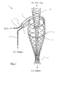
Anhand der Zeichnung soll ein Ausführungsbeispiel der Erfindung näher erläutert werden. Die einzige Zeichnung (
Die in
Beabstandet von der Entspannungsdüse 2 mündet in die Zuführung 4 des Zyklons 5 eine Austrittsdüse 7 für ein Kaltgas ein, die an eine thermisch isolierte Kaltgaszuleitung 8 angeschlossen ist. Beim Kaltgas handelt es sich beispielsweise um kalten gasförmigen Stickstoff, der (hier nicht gezeigt) im flüssigen Zustand in einem Tank bevorratet wird und nach Durchlaufen eines Verdampfers, beispielsweise eines hier nicht gezeigten Wärmetauschers zum Unterkühlen des flüssigen CO2 in der Zuleitung 3, der Austrittsdüse 7 mit einer Temperatur von unter minus 150°C (123 K) zugeführt wird. Alternativ kann auch flüssiger Stickstoff mit einer Temperatur von minus 196°C, (77 K) (1 bar) oder ein anderes kryogenes Gas im gasförmigen oder verflüssigten Zustand als Kaltgas zum Einsatz kommen. Der mit thermisch isolierten Wänden 9 ausgerüstete Zyklon 5 besitzt des weiteren in an sich bekannter Weise einen (geodätisch) nach unten gerichteten Produktaustritt 11 und einen mit dem Innern des Zyklons 5 im Bereich von dessen Achse strömungsverbundenen Gasaustritt 12. Entspannungsdüse 2 und Austrittsdüse 7 können im Übrigen auch Ausmündungen einer außenmischenden Zweistoffdüse darstellen.Spaced from the
Beim Betrieb der Vorrichtung 1 strömt flüssiges Kohlendioxid unter einem Druck von mehr als 5,18 bar abs., beispielsweise einem Druck zwischen 10 bis 30 bar, durch die Druckleitung 3 und entspannt an der Entspannungsdüse 2 unter Bildung eines Gemisches aus Kohlendioxidgas und Kohlendioxidschnee, wobei es sich auf eine Temperatur von -78,9°C (194 K) abkühlt. Das Gemisch aus Kohlendioxidgas und Kohlendioxidschnee strömt über die Zuführung 4 in den Zyklon 5 ein. Zugleich wird ein kaltes kryogenes Gas, beispielsweise kalter gasförmiger Stickstoff, über die Kaltgaszuleitung 8 herangeführt und strömt an der Austrittsdüse 7 ebenfalls in die Zuführung 4 und von dort in den Zyklon 5. Entspannungsdüse 2 und Austrittsdüse 7 sind so angeordnet, dass die ihnen jeweils entweichenden Ströme im Wesentlichen parallel durch die Zuführung 4 strömen. Im Innern des Zyklons 5 kommt es aufgrund der dort vorherrschenden Strömungen zu einer innigen Vermischung von Kohlendioxidgas und Kohlendioxidpartikeln einerseits und Kaltgas andererseits. Aufgrund der tieferen Temperatur des Kaltgases werden die Kohlendioxidpartikel dabei auf eine Temperatur deutlich unterhalb der Sublimationstemperatur von Kohlendioxid bei Atmosphärendruck abgekühlt (unterkühlt), beispielsweise auf eine Temperatur von ca. -100°C (173 K). Durch die kreisförmigen Strömungen werden die Kohlendioxidpartikel aufgrund der Fliehkraft an die Kegelwände geschleudert und soweit abgebremst, dass sie sich aus der Strömung lösen und nach unten in Richtung des Produktaustritts 11 rieseln. Von dort werden sie beispielsweise auf die Oberfläche eines zu kühlenden Gegenstandes aufgetragen. Aufgrund der Unterkühlung der Kohlendioxidpartikel sublimiert das Kohlendioxid nicht unmittelbar beim Auftreffen auf den zu kühlenden Gegenstand, da ein Teil der dem Gegenstand entzogenen Wärme zur Aufwärmung der Kohlendioxidpartikel bis zum Erreichen der Sublimationstemperatur aufgewandt werden muss.During operation of the device 1 liquid carbon dioxide flows under a pressure of more than 5.18 bar abs., For example, a pressure between 10 to 30 bar, through the
Das am Gasaustritt 12 entweichende kalte, überwiegend aus gasförmigem Stickstoff und gasförmigem Kohlendioxid bestehende Gas wird bevorzugt aufgefangen und beispielsweise zur Vorkühlung des flüssigen Kohlendioxids in der Druckleitung 3 eingesetzt. Alternativ kann zumindest ein Teilstrom des aus dem Gasaustritt 12 entweichenden Gasgemisches rückgeführt und in die Kaltgaszuleitung 8, die Zuführung 4 des Zyklons 5 und/oder in direkt in den Zyklon 5 eingeleitet werden, um die Restkälte des Gasgemisches zur Unterkühlung der Kohlendioxidpartikel zu nutzen.The escaping at the
Weiterhin kann der Produktaustritt 11 in einem hier gleichfalls nicht gezeigten Schneehorn integriert sein, dass im weiteren Verfahrensablauf beispielsweise für eine flächige Verteilung der aus dem Produktaustritt 11 austretenden unterkühlten Kohlendioxidpartikel auf die zu kühlende Oberfläche sorgt.
Claims (8)
dadurch gekennzeichnet,
dass der aus der Kohlendioxid-Entspannungsdüse (2) austretende Strom aus Kohlendioxidschnee und Kohlendioxidgas in einer Kühl- und Trenneinrichtung (5) mit einem aus einer Kaltgas-Austrittsdüse (7) austretenden Strom eines Kaltgases durchmischt und unterkühlt wird, und anschließend die Kohlendioxidteilchen von dem gasförmigem Gemisch aus Kohlendioxidgas und Kaltgas zumindest teilweise getrennt werden.A process for cooling products, wherein liquid carbon dioxide introduced under pressure is depressurized at a carbon dioxide expansion nozzle (2) to carbon dioxide gas and carbon dioxide snow and the carbon dioxide snow is used to cool a product,
characterized,
in that the stream of carbon dioxide snow and carbon dioxide gas emerging from the carbon dioxide expansion nozzle (2) is mixed with a stream of cold gas leaving a cold gas outlet nozzle (7) and subcooled, and then the carbon dioxide particles of the gaseous mixture of carbon dioxide gas and cold gas are at least partially separated.
Priority Applications (1)
| Application Number | Priority Date | Filing Date | Title |
|---|---|---|---|
| PL13163560T PL2656741T3 (en) | 2012-04-27 | 2013-04-12 | Method and device for cooling products |
Applications Claiming Priority (1)
| Application Number | Priority Date | Filing Date | Title |
|---|---|---|---|
| DE102012008592A DE102012008592A1 (en) | 2012-04-27 | 2012-04-27 | Method and device for cooling products |
Publications (3)
| Publication Number | Publication Date |
|---|---|
| EP2656741A2 true EP2656741A2 (en) | 2013-10-30 |
| EP2656741A3 EP2656741A3 (en) | 2017-11-29 |
| EP2656741B1 EP2656741B1 (en) | 2020-10-28 |
Family
ID=48095687
Family Applications (1)
| Application Number | Title | Priority Date | Filing Date |
|---|---|---|---|
| EP13163560.9A Active EP2656741B1 (en) | 2012-04-27 | 2013-04-12 | Method and device for cooling products |
Country Status (5)
| Country | Link |
|---|---|
| EP (1) | EP2656741B1 (en) |
| DE (1) | DE102012008592A1 (en) |
| ES (1) | ES2841066T3 (en) |
| HU (1) | HUE053040T2 (en) |
| PL (1) | PL2656741T3 (en) |
Cited By (2)
| Publication number | Priority date | Publication date | Assignee | Title |
|---|---|---|---|---|
| DE102014018981A1 (en) | 2014-12-18 | 2016-06-23 | Messer France S.A.S | Method and apparatus for producing supercooled carbon dioxide snow |
| EP3742070A4 (en) * | 2018-01-19 | 2021-10-20 | The Doshisha | Cyclone refrigeration device, cyclone coolness/heat recovery unit, and heat pump system provided with said cyclone refrigeration device or cyclone coolness/heat recovery unit |
Families Citing this family (1)
| Publication number | Priority date | Publication date | Assignee | Title |
|---|---|---|---|---|
| EP4083545A1 (en) * | 2021-04-01 | 2022-11-02 | L'Air Liquide, société anonyme pour l'Étude et l'Exploitation des procédés Georges Claude | New low pressure carbon snow injector |
Citations (2)
| Publication number | Priority date | Publication date | Assignee | Title |
|---|---|---|---|---|
| EP1887296A2 (en) | 2006-08-08 | 2008-02-13 | Linde Aktiengesellschaft | Device and method for the supply of a mixture of cryogenic and cryogenic or non-cryogenic agents into a freezer or cooler unit |
| US20100047424A1 (en) | 2006-05-18 | 2010-02-25 | L'air Liquide Societe Anonyme Pour L'etude Et L'exploitation Des Procedes Georges Claude | Use of a Mixture of Carbon Dioxide Snow and Liquid Nitrogen in Quick Freezing Applications |
Family Cites Families (3)
| Publication number | Priority date | Publication date | Assignee | Title |
|---|---|---|---|---|
| FR2253193A1 (en) * | 1973-12-03 | 1975-06-27 | Air Liquide | Refrigeration of prods partic food prods - using carbon dioxide snow |
| US8691308B2 (en) * | 2009-05-21 | 2014-04-08 | American Air Liquide, Inc. | Method and system for treating food items with an additive and solid carbon dioxide |
| FR2953370B1 (en) * | 2009-12-08 | 2012-08-03 | Air Liquide | METHOD AND INSTALLATION FOR COOLING AND / OR FREEZING PRODUCTS, IN PARTICULAR FOOD PRODUCTS, USING THE INJECTION OF TWO CRYOGENIC LIQUIDS |
-
2012
- 2012-04-27 DE DE102012008592A patent/DE102012008592A1/en not_active Withdrawn
-
2013
- 2013-04-12 EP EP13163560.9A patent/EP2656741B1/en active Active
- 2013-04-12 HU HUE13163560A patent/HUE053040T2/en unknown
- 2013-04-12 PL PL13163560T patent/PL2656741T3/en unknown
- 2013-04-12 ES ES13163560T patent/ES2841066T3/en active Active
Patent Citations (2)
| Publication number | Priority date | Publication date | Assignee | Title |
|---|---|---|---|---|
| US20100047424A1 (en) | 2006-05-18 | 2010-02-25 | L'air Liquide Societe Anonyme Pour L'etude Et L'exploitation Des Procedes Georges Claude | Use of a Mixture of Carbon Dioxide Snow and Liquid Nitrogen in Quick Freezing Applications |
| EP1887296A2 (en) | 2006-08-08 | 2008-02-13 | Linde Aktiengesellschaft | Device and method for the supply of a mixture of cryogenic and cryogenic or non-cryogenic agents into a freezer or cooler unit |
Cited By (2)
| Publication number | Priority date | Publication date | Assignee | Title |
|---|---|---|---|---|
| DE102014018981A1 (en) | 2014-12-18 | 2016-06-23 | Messer France S.A.S | Method and apparatus for producing supercooled carbon dioxide snow |
| EP3742070A4 (en) * | 2018-01-19 | 2021-10-20 | The Doshisha | Cyclone refrigeration device, cyclone coolness/heat recovery unit, and heat pump system provided with said cyclone refrigeration device or cyclone coolness/heat recovery unit |
Also Published As
| Publication number | Publication date |
|---|---|
| EP2656741B1 (en) | 2020-10-28 |
| DE102012008592A1 (en) | 2013-10-31 |
| HUE053040T2 (en) | 2021-06-28 |
| PL2656741T3 (en) | 2021-04-19 |
| EP2656741A3 (en) | 2017-11-29 |
| ES2841066T3 (en) | 2021-07-07 |
Similar Documents
| Publication | Publication Date | Title |
|---|---|---|
| EP0744992A1 (en) | Process for preparing particles or powders | |
| DE102005037080A1 (en) | Method and apparatus for cooling cement or cementitious powders | |
| EP2657631B1 (en) | Method and device for cooling products | |
| EP2656741B1 (en) | Method and device for cooling products | |
| DE102015101415A1 (en) | Process and plant for the purification of raw gases by means of physical gas scrubbing | |
| EP2667116B1 (en) | Method and device for cooling | |
| EP1612495B1 (en) | Method and apparatus for cooling products | |
| DE102004018133B3 (en) | Dry ice beam arrangement e.g. for cleaning of surfaces, has source for liquid CO2, nozzle jet with nozzle exit opening for dry ice particle jet as well as line for transfer of CO2 of source to nozzle jet | |
| DE2152793C3 (en) | Process for the production of a freeze-dried coffee extract powder with a bulk density of 200 to 250 g / l and the color of ground coffee | |
| DE1170435B (en) | Process for the liquefaction of a gas to be stored in the liquid state under low pressure | |
| DE102004062670B4 (en) | Method and device for cooling cement | |
| WO2016097018A1 (en) | Method and device for producing subcooled carbon dioxide snow | |
| DE102004011194A1 (en) | Process and apparatus for producing solid carbon dioxide particles | |
| DE102018002750B4 (en) | Device for cooling products | |
| DE4113512A1 (en) | Freeze drying and powdering food prods. - by withdrawing cooling medium e.g. carbon di:oxide, from crystallising chamber and compressing, liquefying and recirculating to the chamber | |
| EP3180163B1 (en) | Jet cutting device and jet cutting method | |
| DE2061184C (en) | Process for grinding grainy materials, in particular plastic granules, at low temperatures | |
| WO2006045305A2 (en) | Method and device for producing solid particles from liquids, in particular liquid carbon dioxide | |
| EP2657630A2 (en) | Method and device for producing cooled products | |
| DE102010047544A1 (en) | Method for extracting of liquid helium from feed fraction containing helium, nitrogen and methane and/or oxygen in liquid helium trailer, involves subjecting nitrogen-containing fraction to cryogenic adsorptive cleaning process | |
| DE2256790A1 (en) | Deep dreezing extract or suspension - directly in powder form by contact with liquefied gas spray obviating crushing or grinding | |
| DE4436384C2 (en) | Method and device for liquefying gases and gas mixtures | |
| DE840561C (en) | Process for cleaning and cooling compressed gas mixtures to be separated | |
| DE1927801B2 (en) | PROCESS FOR THE PRODUCTION OF GRANULES BY FREEZE-DRYING | |
| DE1108669B (en) | Process for the formation of solid spheres from melts of substances that are solid at ordinary temperature by running the melt into a coolant |
Legal Events
| Date | Code | Title | Description |
|---|---|---|---|
| PUAI | Public reference made under article 153(3) epc to a published international application that has entered the european phase |
Free format text: ORIGINAL CODE: 0009012 |
|
| AK | Designated contracting states |
Kind code of ref document: A2 Designated state(s): AL AT BE BG CH CY CZ DE DK EE ES FI FR GB GR HR HU IE IS IT LI LT LU LV MC MK MT NL NO PL PT RO RS SE SI SK SM TR |
|
| AX | Request for extension of the european patent |
Extension state: BA ME |
|
| PUAL | Search report despatched |
Free format text: ORIGINAL CODE: 0009013 |
|
| AK | Designated contracting states |
Kind code of ref document: A3 Designated state(s): AL AT BE BG CH CY CZ DE DK EE ES FI FR GB GR HR HU IE IS IT LI LT LU LV MC MK MT NL NO PL PT RO RS SE SI SK SM TR |
|
| AX | Request for extension of the european patent |
Extension state: BA ME |
|
| RIC1 | Information provided on ipc code assigned before grant |
Ipc: A23L 3/375 20060101AFI20171025BHEP Ipc: F25D 3/12 20060101ALI20171025BHEP |
|
| STAA | Information on the status of an ep patent application or granted ep patent |
Free format text: STATUS: REQUEST FOR EXAMINATION WAS MADE |
|
| 17P | Request for examination filed |
Effective date: 20180529 |
|
| RAX | Requested extension states of the european patent have changed |
Extension state: BA Payment date: 20180529 Extension state: ME Payment date: 20180529 |
|
| RBV | Designated contracting states (corrected) |
Designated state(s): AL AT BE BG CH CY CZ DE DK EE ES FI FR GB GR HR HU IE IS IT LI LT LU LV MC MK MT NL NO PL PT RO RS SE SI SK SM TR |
|
| GRAP | Despatch of communication of intention to grant a patent |
Free format text: ORIGINAL CODE: EPIDOSNIGR1 |
|
| STAA | Information on the status of an ep patent application or granted ep patent |
Free format text: STATUS: GRANT OF PATENT IS INTENDED |
|
| INTG | Intention to grant announced |
Effective date: 20200624 |
|
| GRAS | Grant fee paid |
Free format text: ORIGINAL CODE: EPIDOSNIGR3 |
|
| RIN1 | Information on inventor provided before grant (corrected) |
Inventor name: TEBIB, EMIR Inventor name: GOCKEL, FRANK |
|
| GRAA | (expected) grant |
Free format text: ORIGINAL CODE: 0009210 |
|
| STAA | Information on the status of an ep patent application or granted ep patent |
Free format text: STATUS: THE PATENT HAS BEEN GRANTED |
|
| AK | Designated contracting states |
Kind code of ref document: B1 Designated state(s): AL AT BE BG CH CY CZ DE DK EE ES FI FR GB GR HR HU IE IS IT LI LT LU LV MC MK MT NL NO PL PT RO RS SE SI SK SM TR |
|
| AX | Request for extension of the european patent |
Extension state: BA ME |
|
| REG | Reference to a national code |
Ref country code: GB Ref legal event code: FG4D Free format text: NOT ENGLISH |
|
| REG | Reference to a national code |
Ref country code: CH Ref legal event code: EP |
|
| REG | Reference to a national code |
Ref country code: AT Ref legal event code: REF Ref document number: 1327286 Country of ref document: AT Kind code of ref document: T Effective date: 20201115 |
|
| REG | Reference to a national code |
Ref country code: DE Ref legal event code: R096 Ref document number: 502013015238 Country of ref document: DE |
|
| REG | Reference to a national code |
Ref country code: IE Ref legal event code: FG4D Free format text: LANGUAGE OF EP DOCUMENT: GERMAN |
|
| REG | Reference to a national code |
Ref country code: NL Ref legal event code: FP |
|
| PG25 | Lapsed in a contracting state [announced via postgrant information from national office to epo] |
Ref country code: NO Free format text: LAPSE BECAUSE OF FAILURE TO SUBMIT A TRANSLATION OF THE DESCRIPTION OR TO PAY THE FEE WITHIN THE PRESCRIBED TIME-LIMIT Effective date: 20210128 Ref country code: PT Free format text: LAPSE BECAUSE OF FAILURE TO SUBMIT A TRANSLATION OF THE DESCRIPTION OR TO PAY THE FEE WITHIN THE PRESCRIBED TIME-LIMIT Effective date: 20210301 Ref country code: FI Free format text: LAPSE BECAUSE OF FAILURE TO SUBMIT A TRANSLATION OF THE DESCRIPTION OR TO PAY THE FEE WITHIN THE PRESCRIBED TIME-LIMIT Effective date: 20201028 Ref country code: RS Free format text: LAPSE BECAUSE OF FAILURE TO SUBMIT A TRANSLATION OF THE DESCRIPTION OR TO PAY THE FEE WITHIN THE PRESCRIBED TIME-LIMIT Effective date: 20201028 Ref country code: GR Free format text: LAPSE BECAUSE OF FAILURE TO SUBMIT A TRANSLATION OF THE DESCRIPTION OR TO PAY THE FEE WITHIN THE PRESCRIBED TIME-LIMIT Effective date: 20210129 |
|
| REG | Reference to a national code |
Ref country code: LT Ref legal event code: MG4D |
|
| PG25 | Lapsed in a contracting state [announced via postgrant information from national office to epo] |
Ref country code: BG Free format text: LAPSE BECAUSE OF FAILURE TO SUBMIT A TRANSLATION OF THE DESCRIPTION OR TO PAY THE FEE WITHIN THE PRESCRIBED TIME-LIMIT Effective date: 20210128 Ref country code: IS Free format text: LAPSE BECAUSE OF FAILURE TO SUBMIT A TRANSLATION OF THE DESCRIPTION OR TO PAY THE FEE WITHIN THE PRESCRIBED TIME-LIMIT Effective date: 20210228 Ref country code: LV Free format text: LAPSE BECAUSE OF FAILURE TO SUBMIT A TRANSLATION OF THE DESCRIPTION OR TO PAY THE FEE WITHIN THE PRESCRIBED TIME-LIMIT Effective date: 20201028 Ref country code: SE Free format text: LAPSE BECAUSE OF FAILURE TO SUBMIT A TRANSLATION OF THE DESCRIPTION OR TO PAY THE FEE WITHIN THE PRESCRIBED TIME-LIMIT Effective date: 20201028 |
|
| REG | Reference to a national code |
Ref country code: HU Ref legal event code: AG4A Ref document number: E053040 Country of ref document: HU |
|
| PG25 | Lapsed in a contracting state [announced via postgrant information from national office to epo] |
Ref country code: HR Free format text: LAPSE BECAUSE OF FAILURE TO SUBMIT A TRANSLATION OF THE DESCRIPTION OR TO PAY THE FEE WITHIN THE PRESCRIBED TIME-LIMIT Effective date: 20201028 |
|
| REG | Reference to a national code |
Ref country code: ES Ref legal event code: FG2A Ref document number: 2841066 Country of ref document: ES Kind code of ref document: T3 Effective date: 20210707 |
|
| REG | Reference to a national code |
Ref country code: DE Ref legal event code: R097 Ref document number: 502013015238 Country of ref document: DE |
|
| PG25 | Lapsed in a contracting state [announced via postgrant information from national office to epo] |
Ref country code: SM Free format text: LAPSE BECAUSE OF FAILURE TO SUBMIT A TRANSLATION OF THE DESCRIPTION OR TO PAY THE FEE WITHIN THE PRESCRIBED TIME-LIMIT Effective date: 20201028 Ref country code: CZ Free format text: LAPSE BECAUSE OF FAILURE TO SUBMIT A TRANSLATION OF THE DESCRIPTION OR TO PAY THE FEE WITHIN THE PRESCRIBED TIME-LIMIT Effective date: 20201028 Ref country code: EE Free format text: LAPSE BECAUSE OF FAILURE TO SUBMIT A TRANSLATION OF THE DESCRIPTION OR TO PAY THE FEE WITHIN THE PRESCRIBED TIME-LIMIT Effective date: 20201028 Ref country code: SK Free format text: LAPSE BECAUSE OF FAILURE TO SUBMIT A TRANSLATION OF THE DESCRIPTION OR TO PAY THE FEE WITHIN THE PRESCRIBED TIME-LIMIT Effective date: 20201028 Ref country code: RO Free format text: LAPSE BECAUSE OF FAILURE TO SUBMIT A TRANSLATION OF THE DESCRIPTION OR TO PAY THE FEE WITHIN THE PRESCRIBED TIME-LIMIT Effective date: 20201028 Ref country code: LT Free format text: LAPSE BECAUSE OF FAILURE TO SUBMIT A TRANSLATION OF THE DESCRIPTION OR TO PAY THE FEE WITHIN THE PRESCRIBED TIME-LIMIT Effective date: 20201028 |
|
| PG25 | Lapsed in a contracting state [announced via postgrant information from national office to epo] |
Ref country code: DK Free format text: LAPSE BECAUSE OF FAILURE TO SUBMIT A TRANSLATION OF THE DESCRIPTION OR TO PAY THE FEE WITHIN THE PRESCRIBED TIME-LIMIT Effective date: 20201028 |
|
| PLBE | No opposition filed within time limit |
Free format text: ORIGINAL CODE: 0009261 |
|
| STAA | Information on the status of an ep patent application or granted ep patent |
Free format text: STATUS: NO OPPOSITION FILED WITHIN TIME LIMIT |
|
| 26N | No opposition filed |
Effective date: 20210729 |
|
| PG25 | Lapsed in a contracting state [announced via postgrant information from national office to epo] |
Ref country code: AL Free format text: LAPSE BECAUSE OF FAILURE TO SUBMIT A TRANSLATION OF THE DESCRIPTION OR TO PAY THE FEE WITHIN THE PRESCRIBED TIME-LIMIT Effective date: 20201028 Ref country code: IT Free format text: LAPSE BECAUSE OF FAILURE TO SUBMIT A TRANSLATION OF THE DESCRIPTION OR TO PAY THE FEE WITHIN THE PRESCRIBED TIME-LIMIT Effective date: 20201028 |
|
| PG25 | Lapsed in a contracting state [announced via postgrant information from national office to epo] |
Ref country code: SI Free format text: LAPSE BECAUSE OF FAILURE TO SUBMIT A TRANSLATION OF THE DESCRIPTION OR TO PAY THE FEE WITHIN THE PRESCRIBED TIME-LIMIT Effective date: 20201028 Ref country code: MC Free format text: LAPSE BECAUSE OF FAILURE TO SUBMIT A TRANSLATION OF THE DESCRIPTION OR TO PAY THE FEE WITHIN THE PRESCRIBED TIME-LIMIT Effective date: 20201028 |
|
| GBPC | Gb: european patent ceased through non-payment of renewal fee |
Effective date: 20210412 |
|
| PG25 | Lapsed in a contracting state [announced via postgrant information from national office to epo] |
Ref country code: LU Free format text: LAPSE BECAUSE OF NON-PAYMENT OF DUE FEES Effective date: 20210412 |
|
| REG | Reference to a national code |
Ref country code: DE Ref legal event code: R081 Ref document number: 502013015238 Country of ref document: DE Owner name: MESSER SE & CO. KGAA, DE Free format text: FORMER OWNERS: MESSER FRANCE S.A.S., PUTEAUX, FR; MESSER GROUP GMBH, 65812 BAD SODEN, DE Ref country code: DE Ref legal event code: R081 Ref document number: 502013015238 Country of ref document: DE Owner name: MESSER FRANCE S.A.S, FR Free format text: FORMER OWNERS: MESSER FRANCE S.A.S., PUTEAUX, FR; MESSER GROUP GMBH, 65812 BAD SODEN, DE |
|
| PG25 | Lapsed in a contracting state [announced via postgrant information from national office to epo] |
Ref country code: LI Free format text: LAPSE BECAUSE OF NON-PAYMENT OF DUE FEES Effective date: 20210430 Ref country code: CH Free format text: LAPSE BECAUSE OF NON-PAYMENT OF DUE FEES Effective date: 20210430 Ref country code: GB Free format text: LAPSE BECAUSE OF NON-PAYMENT OF DUE FEES Effective date: 20210412 |
|
| PG25 | Lapsed in a contracting state [announced via postgrant information from national office to epo] |
Ref country code: IE Free format text: LAPSE BECAUSE OF NON-PAYMENT OF DUE FEES Effective date: 20210412 |
|
| PG25 | Lapsed in a contracting state [announced via postgrant information from national office to epo] |
Ref country code: IS Free format text: LAPSE BECAUSE OF FAILURE TO SUBMIT A TRANSLATION OF THE DESCRIPTION OR TO PAY THE FEE WITHIN THE PRESCRIBED TIME-LIMIT Effective date: 20210228 |
|
| PGFP | Annual fee paid to national office [announced via postgrant information from national office to epo] |
Ref country code: FR Payment date: 20230309 Year of fee payment: 11 |
|
| PGFP | Annual fee paid to national office [announced via postgrant information from national office to epo] |
Ref country code: PL Payment date: 20230314 Year of fee payment: 11 Ref country code: BE Payment date: 20230315 Year of fee payment: 11 |
|
| PG25 | Lapsed in a contracting state [announced via postgrant information from national office to epo] |
Ref country code: CY Free format text: LAPSE BECAUSE OF FAILURE TO SUBMIT A TRANSLATION OF THE DESCRIPTION OR TO PAY THE FEE WITHIN THE PRESCRIBED TIME-LIMIT Effective date: 20201028 |
|
| PGFP | Annual fee paid to national office [announced via postgrant information from national office to epo] |
Ref country code: ES Payment date: 20230511 Year of fee payment: 11 Ref country code: DE Payment date: 20230430 Year of fee payment: 11 |
|
| PGFP | Annual fee paid to national office [announced via postgrant information from national office to epo] |
Ref country code: HU Payment date: 20230320 Year of fee payment: 11 Ref country code: AT Payment date: 20230327 Year of fee payment: 11 |
|
| PGFP | Annual fee paid to national office [announced via postgrant information from national office to epo] |
Ref country code: NL Payment date: 20240315 Year of fee payment: 12 |
|
| PG25 | Lapsed in a contracting state [announced via postgrant information from national office to epo] |
Ref country code: MK Free format text: LAPSE BECAUSE OF FAILURE TO SUBMIT A TRANSLATION OF THE DESCRIPTION OR TO PAY THE FEE WITHIN THE PRESCRIBED TIME-LIMIT Effective date: 20201028 |