EP2655834B1 - Injection aperture for a steam power plant - Google Patents
Injection aperture for a steam power plant Download PDFInfo
- Publication number
- EP2655834B1 EP2655834B1 EP12704399.0A EP12704399A EP2655834B1 EP 2655834 B1 EP2655834 B1 EP 2655834B1 EP 12704399 A EP12704399 A EP 12704399A EP 2655834 B1 EP2655834 B1 EP 2655834B1
- Authority
- EP
- European Patent Office
- Prior art keywords
- injection
- injection line
- line
- aperture
- steam
- Prior art date
- Legal status (The legal status is an assumption and is not a legal conclusion. Google has not performed a legal analysis and makes no representation as to the accuracy of the status listed.)
- Not-in-force
Links
- 238000002347 injection Methods 0.000 title claims description 132
- 239000007924 injection Substances 0.000 title claims description 132
- XLYOFNOQVPJJNP-UHFFFAOYSA-N water Substances O XLYOFNOQVPJJNP-UHFFFAOYSA-N 0.000 claims description 30
- 238000000034 method Methods 0.000 claims description 8
- 238000001816 cooling Methods 0.000 claims description 3
- 230000001105 regulatory effect Effects 0.000 claims 4
- 238000011161 development Methods 0.000 description 5
- 230000018109 developmental process Effects 0.000 description 5
- 239000000498 cooling water Substances 0.000 description 2
- 230000003628 erosive effect Effects 0.000 description 2
- 230000007423 decrease Effects 0.000 description 1
- 230000009977 dual effect Effects 0.000 description 1
- 230000035515 penetration Effects 0.000 description 1
- 230000003716 rejuvenation Effects 0.000 description 1
- 239000000243 solution Substances 0.000 description 1
Images
Classifications
-
- F—MECHANICAL ENGINEERING; LIGHTING; HEATING; WEAPONS; BLASTING
- F01—MACHINES OR ENGINES IN GENERAL; ENGINE PLANTS IN GENERAL; STEAM ENGINES
- F01K—STEAM ENGINE PLANTS; STEAM ACCUMULATORS; ENGINE PLANTS NOT OTHERWISE PROVIDED FOR; ENGINES USING SPECIAL WORKING FLUIDS OR CYCLES
- F01K9/00—Plants characterised by condensers arranged or modified to co-operate with the engines
- F01K9/04—Plants characterised by condensers arranged or modified to co-operate with the engines with dump valves to by-pass stages
-
- F—MECHANICAL ENGINEERING; LIGHTING; HEATING; WEAPONS; BLASTING
- F28—HEAT EXCHANGE IN GENERAL
- F28C—HEAT-EXCHANGE APPARATUS, NOT PROVIDED FOR IN ANOTHER SUBCLASS, IN WHICH THE HEAT-EXCHANGE MEDIA COME INTO DIRECT CONTACT WITHOUT CHEMICAL INTERACTION
- F28C3/00—Other direct-contact heat-exchange apparatus
- F28C3/06—Other direct-contact heat-exchange apparatus the heat-exchange media being a liquid and a gas or vapour
-
- B—PERFORMING OPERATIONS; TRANSPORTING
- B01—PHYSICAL OR CHEMICAL PROCESSES OR APPARATUS IN GENERAL
- B01F—MIXING, e.g. DISSOLVING, EMULSIFYING OR DISPERSING
- B01F25/00—Flow mixers; Mixers for falling materials, e.g. solid particles
- B01F25/30—Injector mixers
- B01F25/31—Injector mixers in conduits or tubes through which the main component flows
- B01F25/313—Injector mixers in conduits or tubes through which the main component flows wherein additional components are introduced in the centre of the conduit
- B01F25/3133—Injector mixers in conduits or tubes through which the main component flows wherein additional components are introduced in the centre of the conduit characterised by the specific design of the injector
- B01F25/31332—Ring, torus, toroidal or coiled configurations
Definitions
- the invention relates to an injection orifice for mixing water and steam in a pipeline, wherein means for injecting water are provided in the injection orifice. Furthermore, the invention relates to a method for cooling a vapor, wherein the vapor flows through an injection orifice.
- steam turbines are fluidly connected via comparatively complicated pipelines to a steam generator.
- hot steam is generated, which is usually led to a high-pressure or medium-pressure turbine section.
- the steam generated by the steam generator flows directly to the high-pressure or medium-pressure turbine section.
- the steam must not necessarily flow directly to the turbine, but must be diverted to the condenser.
- the condenser the steam is converted back into water.
- diverter stations are used in these power plants described above, whose task is to direct the steam coming from the steam generator completely or partially directly into the condenser.
- the bypass station is used in addition to the regular continuous operation during the so-called start-up or shutdown.
- a diverter station displays the document WO2010 / 034659A2 .
- the steam is conducted via the bypass station to the condenser, the steam is passed via a diverter valve and a short pipe to an injection orifice. After flowing through the bypass valve, the short pipe and the injection orifice, the pressure of the steam decreases.
- the steam is cooled to be controlled with the condenser to a tuned level.
- the single-stage injection orifice is for a maximum injection quantity designed for water. Under unfavorable circumstances, this can lead to a poor mixing of the steam with the water in the partial load operation of the bypass station, when comparatively little cooling water is required. This could lead to erosion and temperature problems in the downstream condenser.
- the invention begins, whose task is to provide a way to optimally adapt the steam parameters, especially to be able to adapt to load cases.
- an injection orifice for mixing water and steam in a pipeline according to claim 1, wherein in the aperture a first injection line and a second injection line for injection of water is formed in an injection orifice flow channel, wherein the injection orifice flow channel through a inside injection port flow surface is formed on the injection orifice and the second injection line is arranged in the flow direction after the first injection line.
- the object is achieved by a method for cooling a vapor according to claim 9, wherein the steam flows through an injection orifice, wherein water is injected into the steam via a first injection line and a second injection line.
- the invention is based on the idea that in addition to a singular injection known in the prior art, a dual injection with two injection lines to a better Mixing of the water with the steam leads. This tunes the steam parameters better to the level of the condenser.
- the injection via the first injection line and the second injection line takes place in two stages. This means that 0% - 60% of the injection takes place in the first injection line during a start-up process in which not the full amount of water is needed via a control. For example, in load shedding, etc., the second stage is additionally turned on so that the second stage represented by the second injection pipe realizes the remaining capacity of 60% -100%.
- the modified and inventive injection orifice can not only inject sufficient cooling water mass flow at 100% load, but also ensure a part-load operation of Dampfumleitstation better mixing of the water with the steam.
- the injection port flow-side surface of the injection port on the inside is designed as a Laval nozzle. This basically means that the flow cross-section first tapers and then increases. As a result, the pressure distribution in the injection orifice is optimized.
- the injection orifice is substantially rotationally symmetrical to a rotational symmetry axis and the first injection line is arranged at an angle ⁇ 1 with respect to the injection orifice flow surface, wherein the second injection line is arranged at an angle ⁇ 2 with respect to the injection orifice flow surface, the angles ⁇ 1 and ⁇ 2 can assume values between 10 ° and 80 °.
- Optimum mixing of the steam jet with the water injection jet is possible if the two flow directions (of the steam jet and the water injection jet) are not disposed at an obtuse angle. It would be better to mix at an angle between 10 ° and 80 °. Further advantageous angles are in the range of 20 ° to 70 ° and between 30 ° and 60 °.
- angles ⁇ 1 and ⁇ 2 are substantially identical.
- the first injection line and the second injection line can be connected to a common injection line.
- one valve can be used in the first injection line and in the second injection line.
- a control valve shall be taken into account.
- the first injection line and the second injection line are fluidically connected via a common injection line.
- the second injection line is initially blocked via the valve, so that water can be injected only via the first injection line.
- the second control valve is opened so that it is possible to let up to 100% of the water injection amount flow into the injection orifice, thereby enabling better mixing with the steam jet.
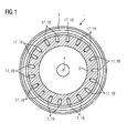
- the FIG. 1 shows a view of an injection orifice 1 seen in a flow direction 2.
- the flow direction 2 in this case shows perpendicular to the plane.
- the injection orifice 1 is arranged within a pipeline 3, this pipeline 3 being arranged in a bypass station in a steam power plant or in a gas turbine power plant. Through this pipe 3 flows a vapor which has been generated in a steam generator.
- the injection orifice 1 is formed substantially rotationally symmetrical to a rotational symmetry axis 4.
- the injection orifice 1 has, within the pipeline 3, an injection orifice flow surface 5 which serves as what is shown in FIG FIG. 2 it can be seen, Laval nozzle is formed.
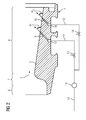
- the FIG. 2 shows a cross-sectional view of the injection orifice 1.
- the injection orifice 1 is substantially characterized in that the injection orifice flow surface 5 is similar to a Laval nozzle.
- the Laval nozzle in a first region 6 has a comparatively large flow cross-section.
- the first region 6 is adjoined by a tapering region 7, in which the flow cross section is reduced.
- a continuous region 8 adjoins, in which the flow channel is continuously expanded.
- a first injection line 9 and a second injection line 10 are arranged.
- the first region 6, the tapering region 7 and the continuous region 8 are viewed in the flow direction 2, arranged one behind the other.
- the first injection line 9 is inclined at an angle ⁇ 1 , which is substantially opposite the injection orifice flow surface 5 is arranged.
- the second injection line 10 is formed at an angle ⁇ 2 with respect to the inflow-flow surface 5.
- the angle ⁇ 1 can assume values between 10 ° - 80 °, 20 ° - 70 °, 30 ° - 60 °.
- the angle ⁇ 2 can assume values between 10 ° - 80 °, 20 ° - 70 ° and 30 ° - 60 °.
- the angles ⁇ 1 and ⁇ 2 may be substantially identical.
- the first injection line 9 opens into a first supply line 11.
- the second injection line 10 opens into a second supply line 12.
- a control valve 13 is arranged in the first supply line 11.
- a control valve 14 is arranged in the second supply line 12.
- the first supply line 11 and the second supply line 12 open into a common injection line 15.
- a measuring device 16 is arranged, which determines the flow rate.
- the second injection line 10 is arranged in the flow direction 2 after the first injection line 9.
- control valve 14 is initially closed, so that no water is flowed into the steam jet via the second injection line 2. If a water capacity of 0% - 60% is required in the steam jet, the control valve 13 is opened, wherein a control regulates the flow rate in the first injection line 9 in the steam jet.
- the control valve 14 is opened, so that a capacity of up to 100% in the steam jet is possible. Therefore, in the second injection pipe 10, the capacity of 60% - 100% is adopted.
- first bore 17 in the injection orifice 1 is arranged between the first injection line 9 and the first supply line 11.
- second bore 18 in the injection orifice 1 is arranged between the second injection line 10 and the second supply line 12.
Landscapes
- Engineering & Computer Science (AREA)
- Mechanical Engineering (AREA)
- General Engineering & Computer Science (AREA)
- Chemical & Material Sciences (AREA)
- Combustion & Propulsion (AREA)
- Nozzles (AREA)
- Control Of Turbines (AREA)
Description
Die Erfindung betrifft eine Einspritzblende zur Vermischung von Wasser und Dampf in einer Rohrleitung, wobei in der Einspritzblende Mittel zur Einspritzung von Wasser vorgesehen sind. Des Weiteren betrifft die Erfindung ein Verfahren zum Abkühlen eines Dampfes, wobei der Dampf durch eine Einspritzblende strömt.The invention relates to an injection orifice for mixing water and steam in a pipeline, wherein means for injecting water are provided in the injection orifice. Furthermore, the invention relates to a method for cooling a vapor, wherein the vapor flows through an injection orifice.
In Dampfkraftwerken sowie in Gas- und Dampfturbinenanlagen werden Dampfturbinen über vergleichsweise komplizierte Rohrleitungen mit einem Dampferzeuger strömungstechnisch verbunden. Im Dampferzeuger wird heißer Dampf erzeugt, der in der Regel zu einer Hochdruck- bzw. Mitteldruck-Teilturbine geführt wird. In einem regelmäßigen Dauerbetrieb strömt der vom Dampferzeuger erzeugte Dampf direkt zu der Hochdruck- bzw. Mitteldruck-Teilturbine. Es gibt allerdings Lastfälle, bei denen der Dampf nicht zwingend direkt zur Turbine strömen darf, sondern umgeleitet werden muss zum Kondensator. Im Kondensator wird der Dampf wieder in Wasser umgewandelt. Dazu werden sogenannte Umleitstationen in diesen vorbeschriebenen Kraftwerken eingesetzt, deren Aufgabe darin besteht, den vom Dampferzeuger kommenden Dampf ganz oder teilweise direkt in den Kondensator zu leiten. Des Weiteren wird die Umleitstation neben dem regulären Dauerbetrieb während der sogenannten Anfahr- oder Abfahrvorgänge verwendet.In steam power plants as well as in gas and steam turbine plants, steam turbines are fluidly connected via comparatively complicated pipelines to a steam generator. In the steam generator hot steam is generated, which is usually led to a high-pressure or medium-pressure turbine section. In a regular continuous operation, the steam generated by the steam generator flows directly to the high-pressure or medium-pressure turbine section. However, there are load cases in which the steam must not necessarily flow directly to the turbine, but must be diverted to the condenser. In the condenser, the steam is converted back into water. For this purpose, so-called diverter stations are used in these power plants described above, whose task is to direct the steam coming from the steam generator completely or partially directly into the condenser. Furthermore, the bypass station is used in addition to the regular continuous operation during the so-called start-up or shutdown.
Eine Umleitstation zeigt das Dokument
Sofern der Dampf über die Umleitstation zum Kondensator geführt wird, wird der Dampf über ein Umleitventil und einer kurzen Rohrleitung zu einer Einspritzblende geleitet. Nach Durchströmen des Umleitventils, der kurzen Rohrleitung und der Einspritzblende sinkt der Druck des Dampfes. Mittels einer Wassereinspritzung wird der Dampf gekühlt, um mit dem Kondensator auf ein abgestimmtes Niveau geregelt zu werden. Die einstufige Einspritzblende wird für eine maximale Einspritzmenge an Wasser ausgelegt. Dies kann unter ungünstigen Umständen dazu führen, dass im Teillastbetrieb der Umleitstation, wenn vergleichsweise wenig Kühlwasser benötigt wird, es zu einer schlechten Vermischung des Dampfes mit dem Wasser kommt. Dies könnte zu Erosions- und Temperaturproblemen im stromabwärts befindlichen Kondensator führen.If the steam is conducted via the bypass station to the condenser, the steam is passed via a diverter valve and a short pipe to an injection orifice. After flowing through the bypass valve, the short pipe and the injection orifice, the pressure of the steam decreases. By means of a water injection, the steam is cooled to be controlled with the condenser to a tuned level. The single-stage injection orifice is for a maximum injection quantity designed for water. Under unfavorable circumstances, this can lead to a poor mixing of the steam with the water in the partial load operation of the bypass station, when comparatively little cooling water is required. This could lead to erosion and temperature problems in the downstream condenser.
Die Auslegung der Einspritzblende und der Wassereinspritzung lediglich für einen Arbeitspunkt ist dementsprechend keine optimale Lösung beim Einsatz in Kraftwerken.The design of the injection orifice and the water injection only for one operating point is therefore not an optimal solution when used in power plants.
An dieser Stelle setzt die Erfindung an, deren Aufgabe es ist, eine Möglichkeit anzugeben, die Dampfparameter optimal anpassen zu können, insbesondere an Lastfälle anpassen zu können.At this point, the invention begins, whose task is to provide a way to optimally adapt the steam parameters, especially to be able to adapt to load cases.
Gelöst wird diese Aufgabe durch eine Einspritzblende zur Vermischung von Wasser und Dampf in einer Rohrleitung gemäß Anspruch 1, wobei in der Blende eine erste Einspritzleitung und eine zweite Einspritzleitung zur Einspritzung von Wasser in einen Einspritzblende-Strömungskanal ausgebildet ist, wobei der Einspritzblenden-Strömungskanal durch eine innenseitige Einspritzblenden-Strömungsoberfläche auf der Einspritzblende gebildet ist und die zweite Einspritzleitung in Strömungsrichtung nach der ersten Einspritzleitung angeordnet ist.This object is achieved by an injection orifice for mixing water and steam in a pipeline according to claim 1, wherein in the aperture a first injection line and a second injection line for injection of water is formed in an injection orifice flow channel, wherein the injection orifice flow channel through a inside injection port flow surface is formed on the injection orifice and the second injection line is arranged in the flow direction after the first injection line.
Des Weiteren wird die Aufgabe gelöst durch ein Verfahren zum Abkühlen eines Dampfes gemäß Anspruch 9, wobei der Dampf durch eine Einspritz-blende strömt, wobei Wasser über eine erste Einspritzleitung und einer zweiten Einspritzleitung in den Dampf eingespritzt wird.Furthermore, the object is achieved by a method for cooling a vapor according to
Vorteilhafte Weiterbildungen sind in den Unteransprüchen angegeben.Advantageous developments are specified in the subclaims.
Die Erfindung geht von dem Gedanken aus, dass neben einer im Stand der Technik bekannten singulären Einspritzung eine duale Einspritzung mit zwei Einspritzleitungen zu einer besseren Durchmischung des Wassers mit dem Dampf führt. Dadurch werden die Dampfparameter besser an das Niveau des Kondensators abgestimmt. Die Einspritzung über die erste Einspritzleitung und die zweite Einspritzleitung erfolgt zweistufig. Das bedeutet, dass während eines Anfahrvorganges, bei der nicht die volle Wassermenge benötigt wird, in der ersten Einspritzleitung 0% - 60% der Einspritzung über eine Regelung erfolgt. Bei beispielsweise Lastabwürfen usw. wird die zweite Stufe zusätzlich eingeschaltet, so dass die zweite Stufe, die durch die zweite Einspritzleitung dargestellt wird, die restliche Kapazität von 60% - 100% realisiert.The invention is based on the idea that in addition to a singular injection known in the prior art, a dual injection with two injection lines to a better Mixing of the water with the steam leads. This tunes the steam parameters better to the level of the condenser. The injection via the first injection line and the second injection line takes place in two stages. This means that 0% - 60% of the injection takes place in the first injection line during a start-up process in which not the full amount of water is needed via a control. For example, in load shedding, etc., the second stage is additionally turned on so that the second stage represented by the second injection pipe realizes the remaining capacity of 60% -100%.
Die Eindringtiefe des Wasserstrahls in den Dampfstrahl wird dadurch während der An- und Abfahrvorgänge verbessert. Die Folge ist, dass Temperatur- und Erosionsprobleme im Kondensator vermieden werden können. Damit wird die modifizierte und erfindungsgemäße Einspritzblende nicht nur einen ausreichenden Kühlwassermassenstrom bei 100% Last einspritzen können, sondern auch eine bei Teillastbetrieb der Dampfumleitstation bessere Vermischung des Wassers mit dem Dampf gewährleisten.The penetration depth of the water jet into the steam jet is thereby improved during start-up and shut-down operations. The result is that temperature and erosion problems in the condenser can be avoided. Thus, the modified and inventive injection orifice can not only inject sufficient cooling water mass flow at 100% load, but also ensure a part-load operation of Dampfumleitstation better mixing of the water with the steam.
In einer ersten vorteilhaften Weiterbildung ist die innenseitige Einspritzblenden-Strömungsoberfläche der Einspritzblende als Lavaldüse ausgebildet. Das bedeutet im Grunde, dass der Strömungsquerschnitt sich zuerst verjüngt und anschließend vergrößert. Dies führt dazu, dass die Druckverteilung in der Einspritzblende optimiert wird.In a first advantageous development, the injection port flow-side surface of the injection port on the inside is designed as a Laval nozzle. This basically means that the flow cross-section first tapers and then increases. As a result, the pressure distribution in the injection orifice is optimized.
In einer weiteren vorteilhaften Weiterbildung ist die Einspritzblende im Wesentlichen rotationssymmetrisch zu einer Rotationssymmetrieachse ausgebildet und die erste Einspritzleitung unter einem Winkel α1 gegenüber der Einspritzblenden-Strömungsoberfläche angeordnet, wobei die zweite Einspritzleitung unter einem Winkel α2 gegenüber der Einspritzblenden-Strömungsoberfläche angeordnet ist, wobei die Winkel α1 und α2 Werte zwischen 10° und 80° annehmen können. Eine optimale Durchmischung des Dampfstrahls mit dem Wassereinspritzstrahl ist möglich, wenn die beiden Strömungsrichtungen (des Dampfstrahls und des Wassereinspritzstrahls) nicht unter einem stumpfen Winkel angeordnet sind. Besser wäre eine Durchmischung unter einem Winkel zwischen 10° und 80°. Weitere vorteilhafte Winkel liegen in Bereichen von 20° bis 70° sowie zwischen 30° und 60°.In a further advantageous development, the injection orifice is substantially rotationally symmetrical to a rotational symmetry axis and the first injection line is arranged at an angle α1 with respect to the injection orifice flow surface, wherein the second injection line is arranged at an angle α2 with respect to the injection orifice flow surface, the angles α1 and α2 can assume values between 10 ° and 80 °. Optimum mixing of the steam jet with the water injection jet is possible if the two flow directions (of the steam jet and the water injection jet) are not disposed at an obtuse angle. It would be better to mix at an angle between 10 ° and 80 °. Further advantageous angles are in the range of 20 ° to 70 ° and between 30 ° and 60 °.
In einer weiteren vorteilhaften Weiterbildung sind die Winkel α1 und α2 im Wesentlichen identisch.In a further advantageous development, the angles α1 and α2 are substantially identical.
In einer weiteren vorteilhaften Weiterbildung der erfindungsgemäßen Vorrichtung ist die erste Einspritzleitung und die zweite Einspritzleitung mit einer gemeinsamen Einspritzleitung verbindbar. Bei dieser Realisierung kann in der ersten Einspritzleitung und in der zweiten Einspritzleitung jeweils ein Ventil eingesetzt werden. Für die erste Einspritzleitung, die für die erste Stufe verantwortlich ist und eine Kapazität von 0% bis 60% der Gesamtmenge in der gemeinsamen Einspritzleitung abdeckt, ist ein Regelventil zu berücksichtigen.In a further advantageous development of the device according to the invention, the first injection line and the second injection line can be connected to a common injection line. In this realization, in each case one valve can be used in the first injection line and in the second injection line. For the first injection line, which is responsible for the first stage and covers a capacity of 0% to 60% of the total quantity in the common injection line, a control valve shall be taken into account.
Für die zweite Einspritzleitung, die für die Kapazität von 60% bis 100% eingesetzt wird, genügt ein Steuerventil.For the second injection line, which is used for the capacity of 60% to 100%, a control valve is sufficient.
Im erfindungsgemäßen Verfahren sind die erste Einspritzleitung und die zweite Einspritzleitung über eine gemeinsame Einspritzleitung strömungstechnisch verbunden. Im erfindungsgemäßen Verfahren wird zunächst die zweite Einspritzleitung über das Ventil versperrt, so dass lediglich über die erste Einspritzleitung Wasser eingespritzt werden kann.In the method according to the invention, the first injection line and the second injection line are fluidically connected via a common injection line. In the method according to the invention, the second injection line is initially blocked via the valve, so that water can be injected only via the first injection line.
Sobald eine erhöhte Kapazität an Wasser benötigt wird, wird das zweite Steuerventil geöffnet, so dass die Möglichkeit besteht, bis zu 100% der Wassereinspritzmenge in die Einspritzblende hineinströmen zu lassen, um dadurch eine bessere Vermischung mit dem Dampfstrahl zu ermöglichen.As soon as an increased capacity of water is required, the second control valve is opened so that it is possible to let up to 100% of the water injection amount flow into the injection orifice, thereby enabling better mixing with the steam jet.
Die Erfindung wird anhand eines Ausführungsbeispiels näher erläutert. Bauteile mit gleichen Bezugszeichen weisen im Wesentlichen die gleiche Wirkungsweise auf.The invention will be explained in more detail with reference to an embodiment. Components with the same reference numbers have essentially the same mode of action.
Es zeigen:
- Figur 1
- eine Draufsicht in Strömungsrichtung auf eine Einspritzblende;
- Figur 2
- eine Querschnittsansicht der Einspritzblende.
- FIG. 1
- a plan view in the flow direction on an injection orifice;
- FIG. 2
- a cross-sectional view of the injection orifice.
Die
Die
Während des Betriebs wird das Steuer-Ventil 14 zunächst geschlossen, so dass über die zweite Einspritzleitung 2 kein Wasser in den Dampfstrahl eingeströmt wird. Sofern im Dampfstrahl eine Wasserkapazität von 0% - 60% benötigt wird, wird das Regel-Ventil 13 geöffnet, wobei eine Regelung die Durchflussmenge in der ersten Einspritzleitung 9 in den Dampfstrahl regelt.During operation, the
Sofern eine erhöhte Kapazität an Wasser im Dampfstrahl benötigt wird, wird das Steuer-Ventil 14 geöffnet, so dass eine Kapazität von bis zu 100% in den Dampfstrahl möglich ist. Daher wird in der zweiten Einspritzleitung 10 die Kapazität von 60% - 100% übernommen.If an increased capacity of water in the steam jet is required, the
Zwischen der ersten Einspritzleitung 9 und der ersten Zuführleitung 11 ist eine erste Bohrung 17 in der Einspritzblende 1 angeordnet. Zwischen der zweiten Einspritzleitung 10 und der zweiten Zuführleitung 12 ist eine zweite Bohrung 18 in der Einspritzblende 1 angeordnet.Between the
Claims (11)
- Injection aperture (1) for mixing water and steam in a pipe (3),
wherein the steam flows in a flow direction (2),
wherein in the injection aperture (1) there are formed a first injection line (9) and a second injection line (10) for injecting water into an injection aperture flow duct, wherein the injection aperture flow duct is formed by an internal injection aperture flow surface (5) on the injection aperture (1),
characterized in that
the second injection line (10) is arranged after the first injection line (9), as seen in the flow direction (2), wherein the first injection line (9) opens into a first supply line (11) in which there is arranged a regulating valve (13),
wherein the second injection line (10) opens into a second supply line (12) in which there is arranged a control valve (14),
wherein the control valve (14) and the regulating valve (13) are designed such that, during operation, at first no steam flows via the second injection line (10). - Injection aperture (1) according to Claim 1,
wherein the regulating valve (13) is designed such that, in the case of a required water capacity of 0% to 60%, the regulating valve (13) is opened and a regulator regulates the throughflow quantity in the first injection line (9). - Injection aperture (1) according to Claim 2,
wherein the control valve (14) is designed such that, in the case of a required water capacity of up to 100%, the control valve (14) is opened. - Injection aperture (1) according to one of the preceding claims,
wherein the internal injection aperture flow surface (5) is designed as a de Laval nozzle. - Injection aperture (1) according to one of the preceding claims,
wherein the injection aperture flow duct is designed such that, in a flow direction (2) of the inflowing steam, it first narrows and then widens. - Injection aperture (1) according to one of the preceding claims,
wherein the injection aperture (1) is designed essentially axisymmetrically with respect to an axis of rotational symmetry (4) and the first injection line (9) is arranged at an angle α1 with respect to the injection aperture flow surface (5),
wherein the second injection line (10) is arranged at an angle α2 with respect to the injection aperture flow surface (5),
wherein α1 and α2 can adopt values between 10° and 80°. - Injection aperture according to Claim 6,
wherein α1 and α2 are essentially identical. - Injection aperture (1) according to one of the preceding claims,
wherein the first injection line (9) and the second injection line (10) can be connected to a common injection line (15). - Method for cooling steam,
wherein the steam flows through an injection aperture (1), wherein water is injected into the steam via a first injection line (9) and a second injection line (10), wherein the second injection line (10) is at first closed and water is injected only via the first injection line (9),
wherein the first injection line (9) and the second injection line (10) are fluidically connected to a common injection line (15) and
wherein the first injection line (9) injects into the steam 0% - 60% of the capacity of the water which can be made to flow in the common injection line (15). - Method according to Claim 9,
wherein the second injection line (10) injects into the steam the remaining 40% - 100% of the capacity of the water which can be made to flow in the common injection line. - Method according to either of Claims 9 and 10,
wherein a first valve (13) is arranged in the first injection line (9) and a second valve (14) is arranged in the second injection line (10).
Priority Applications (1)
| Application Number | Priority Date | Filing Date | Title |
|---|---|---|---|
| EP12704399.0A EP2655834B1 (en) | 2011-03-14 | 2012-02-09 | Injection aperture for a steam power plant |
Applications Claiming Priority (3)
| Application Number | Priority Date | Filing Date | Title |
|---|---|---|---|
| EP11158049A EP2500549A1 (en) | 2011-03-14 | 2011-03-14 | Injection aperture for a steam power plant |
| PCT/EP2012/052192 WO2012123194A1 (en) | 2011-03-14 | 2012-02-09 | Injection aperture for a steam power plant |
| EP12704399.0A EP2655834B1 (en) | 2011-03-14 | 2012-02-09 | Injection aperture for a steam power plant |
Publications (2)
| Publication Number | Publication Date |
|---|---|
| EP2655834A1 EP2655834A1 (en) | 2013-10-30 |
| EP2655834B1 true EP2655834B1 (en) | 2015-10-28 |
Family
ID=44357958
Family Applications (2)
| Application Number | Title | Priority Date | Filing Date |
|---|---|---|---|
| EP11158049A Withdrawn EP2500549A1 (en) | 2011-03-14 | 2011-03-14 | Injection aperture for a steam power plant |
| EP12704399.0A Not-in-force EP2655834B1 (en) | 2011-03-14 | 2012-02-09 | Injection aperture for a steam power plant |
Family Applications Before (1)
| Application Number | Title | Priority Date | Filing Date |
|---|---|---|---|
| EP11158049A Withdrawn EP2500549A1 (en) | 2011-03-14 | 2011-03-14 | Injection aperture for a steam power plant |
Country Status (3)
| Country | Link |
|---|---|
| EP (2) | EP2500549A1 (en) |
| CN (1) | CN103443420B (en) |
| WO (1) | WO2012123194A1 (en) |
Family Cites Families (5)
| Publication number | Priority date | Publication date | Assignee | Title |
|---|---|---|---|---|
| US4372125A (en) * | 1980-12-22 | 1983-02-08 | General Electric Company | Turbine bypass desuperheater control system |
| JPS595811A (en) * | 1982-07-01 | 1984-01-12 | Toshiba Corp | Low pressure turbine by-pass device |
| DE3240453A1 (en) * | 1982-11-02 | 1984-05-03 | Kraftwerk Union AG, 4330 Mülheim | STEAM TURBINE CONDENSER WITH AT LEAST ONE REDUCTION STEAM INTRODUCTION INTO THE STEAM DOME |
| CN86207574U (en) * | 1986-10-13 | 1987-08-19 | 长春市盐城科技开发咨询处 | Direct contact heater with laval nozzle |
| EP2213847A1 (en) * | 2008-09-24 | 2010-08-04 | Siemens Aktiengesellschaft | Steam power assembly for creating electrical energy |
-
2011
- 2011-03-14 EP EP11158049A patent/EP2500549A1/en not_active Withdrawn
-
2012
- 2012-02-09 CN CN201280013635.4A patent/CN103443420B/en not_active Expired - Fee Related
- 2012-02-09 WO PCT/EP2012/052192 patent/WO2012123194A1/en not_active Ceased
- 2012-02-09 EP EP12704399.0A patent/EP2655834B1/en not_active Not-in-force
Also Published As
| Publication number | Publication date |
|---|---|
| EP2500549A1 (en) | 2012-09-19 |
| CN103443420A (en) | 2013-12-11 |
| CN103443420B (en) | 2016-05-18 |
| WO2012123194A1 (en) | 2012-09-20 |
| EP2655834A1 (en) | 2013-10-30 |
Similar Documents
| Publication | Publication Date | Title |
|---|---|---|
| DE102008029941B4 (en) | Steam power plant and method for controlling the power of a steam power plant | |
| DE102006045034A1 (en) | A water cooled constant temperature liquid circulating device and method for controlling the temperature of the circulating liquid | |
| EP3049639B1 (en) | Gas turbine with a bypass line for improved fuel line flushing, and method for flushing a gas turbine | |
| DE102009026053A1 (en) | Overload valve for a steam turbine and associated method | |
| EP2726785A1 (en) | Bypass steam line | |
| DE102011011123B4 (en) | Steam plant and process for configuring the steam plant | |
| EP2129879A2 (en) | Method for operating a multi-step steam turbine | |
| EP2918793A1 (en) | Control concept for district heating decoupling in a steam power plant | |
| DE102011014120A1 (en) | Apparatus for introducing gas stream into turbine of exhaust gas turbocharger or turbo-compound system through exhaust pipe, has gas supply line for gas stream, where connection is formed by multiple bores, which work together with slider | |
| EP2655834B1 (en) | Injection aperture for a steam power plant | |
| EP3643396A1 (en) | Continuously operating and fluid-respiring fluid mixing machine and method for operating same | |
| EP2900944A2 (en) | Gas and steam turbine system having feed-water partial-flow degasser | |
| DE3919074A1 (en) | Pure-water supply system - has insert in ring main reducing pressure with pipe connected | |
| EP2829693A1 (en) | Turbine condenser for a steam turbine | |
| WO2013020829A1 (en) | Bypass steam station | |
| EP3087257A1 (en) | Steam power installation comprising valve-stem leakage steam line | |
| EP1784558A1 (en) | Steam turbine | |
| DE102018129954A1 (en) | Mixing device for a fuel injection system of an internal combustion engine | |
| WO2023036569A1 (en) | Device and method for recirculating anode gas in an anode circuit of a fuel cell system, and fuel cell system | |
| DE102010007662A1 (en) | Geothermal energy distributor for use with geothermal or ground probes, is formed of collecting body with two connecting pieces and connection opening, where connecting pieces are arranged along longitudinal axis of collecting body | |
| EP2478276A1 (en) | Valve for a continuous-flow machine | |
| EP3296506A1 (en) | Assembly for feed of an additional mass flow into a main mass flow | |
| WO2023036570A1 (en) | Device and method for recirculating anode gas in an anode circuit of a fuel cell system, and fuel cell system | |
| DE102021212308A1 (en) | Device and operating method for recirculating anode gas in an anode circuit of a fuel cell system, fuel cell system | |
| EP3109420A1 (en) | Method for cooling a fluid flow engine |
Legal Events
| Date | Code | Title | Description |
|---|---|---|---|
| PUAI | Public reference made under article 153(3) epc to a published international application that has entered the european phase |
Free format text: ORIGINAL CODE: 0009012 |
|
| 17P | Request for examination filed |
Effective date: 20130722 |
|
| AK | Designated contracting states |
Kind code of ref document: A1 Designated state(s): AL AT BE BG CH CY CZ DE DK EE ES FI FR GB GR HR HU IE IS IT LI LT LU LV MC MK MT NL NO PL PT RO RS SE SI SK SM TR |
|
| 17Q | First examination report despatched |
Effective date: 20140423 |
|
| DAX | Request for extension of the european patent (deleted) | ||
| RIC1 | Information provided on ipc code assigned before grant |
Ipc: F01D 19/00 20060101ALI20150408BHEP Ipc: F28C 3/06 20060101ALI20150408BHEP Ipc: F02C 7/141 20060101AFI20150408BHEP Ipc: F01K 9/04 20060101ALI20150408BHEP Ipc: B01F 5/04 20060101ALI20150408BHEP |
|
| GRAP | Despatch of communication of intention to grant a patent |
Free format text: ORIGINAL CODE: EPIDOSNIGR1 |
|
| INTG | Intention to grant announced |
Effective date: 20150521 |
|
| GRAS | Grant fee paid |
Free format text: ORIGINAL CODE: EPIDOSNIGR3 |
|
| GRAA | (expected) grant |
Free format text: ORIGINAL CODE: 0009210 |
|
| AK | Designated contracting states |
Kind code of ref document: B1 Designated state(s): AL AT BE BG CH CY CZ DE DK EE ES FI FR GB GR HR HU IE IS IT LI LT LU LV MC MK MT NL NO PL PT RO RS SE SI SK SM TR |
|
| REG | Reference to a national code |
Ref country code: GB Ref legal event code: FG4D Free format text: NOT ENGLISH |
|
| REG | Reference to a national code |
Ref country code: CH Ref legal event code: EP |
|
| REG | Reference to a national code |
Ref country code: AT Ref legal event code: REF Ref document number: 758083 Country of ref document: AT Kind code of ref document: T Effective date: 20151115 |
|
| REG | Reference to a national code |
Ref country code: IE Ref legal event code: FG4D Free format text: LANGUAGE OF EP DOCUMENT: GERMAN |
|
| REG | Reference to a national code |
Ref country code: DE Ref legal event code: R096 Ref document number: 502012005087 Country of ref document: DE |
|
| REG | Reference to a national code |
Ref country code: CH Ref legal event code: NV Representative=s name: SIEMENS SCHWEIZ AG, CH |
|
| REG | Reference to a national code |
Ref country code: FR Ref legal event code: PLFP Year of fee payment: 5 |
|
| REG | Reference to a national code |
Ref country code: LT Ref legal event code: MG4D |
|
| REG | Reference to a national code |
Ref country code: NL Ref legal event code: MP Effective date: 20151028 |
|
| PG25 | Lapsed in a contracting state [announced via postgrant information from national office to epo] |
Ref country code: NO Free format text: LAPSE BECAUSE OF FAILURE TO SUBMIT A TRANSLATION OF THE DESCRIPTION OR TO PAY THE FEE WITHIN THE PRESCRIBED TIME-LIMIT Effective date: 20160128 Ref country code: ES Free format text: LAPSE BECAUSE OF FAILURE TO SUBMIT A TRANSLATION OF THE DESCRIPTION OR TO PAY THE FEE WITHIN THE PRESCRIBED TIME-LIMIT Effective date: 20151028 Ref country code: NL Free format text: LAPSE BECAUSE OF FAILURE TO SUBMIT A TRANSLATION OF THE DESCRIPTION OR TO PAY THE FEE WITHIN THE PRESCRIBED TIME-LIMIT Effective date: 20151028 Ref country code: HR Free format text: LAPSE BECAUSE OF FAILURE TO SUBMIT A TRANSLATION OF THE DESCRIPTION OR TO PAY THE FEE WITHIN THE PRESCRIBED TIME-LIMIT Effective date: 20151028 Ref country code: LT Free format text: LAPSE BECAUSE OF FAILURE TO SUBMIT A TRANSLATION OF THE DESCRIPTION OR TO PAY THE FEE WITHIN THE PRESCRIBED TIME-LIMIT Effective date: 20151028 Ref country code: IS Free format text: LAPSE BECAUSE OF FAILURE TO SUBMIT A TRANSLATION OF THE DESCRIPTION OR TO PAY THE FEE WITHIN THE PRESCRIBED TIME-LIMIT Effective date: 20160228 |
|
| PGFP | Annual fee paid to national office [announced via postgrant information from national office to epo] |
Ref country code: CZ Payment date: 20160208 Year of fee payment: 5 Ref country code: IT Payment date: 20160225 Year of fee payment: 5 |
|
| PG25 | Lapsed in a contracting state [announced via postgrant information from national office to epo] |
Ref country code: RS Free format text: LAPSE BECAUSE OF FAILURE TO SUBMIT A TRANSLATION OF THE DESCRIPTION OR TO PAY THE FEE WITHIN THE PRESCRIBED TIME-LIMIT Effective date: 20151028 Ref country code: SE Free format text: LAPSE BECAUSE OF FAILURE TO SUBMIT A TRANSLATION OF THE DESCRIPTION OR TO PAY THE FEE WITHIN THE PRESCRIBED TIME-LIMIT Effective date: 20151028 Ref country code: FI Free format text: LAPSE BECAUSE OF FAILURE TO SUBMIT A TRANSLATION OF THE DESCRIPTION OR TO PAY THE FEE WITHIN THE PRESCRIBED TIME-LIMIT Effective date: 20151028 Ref country code: GR Free format text: LAPSE BECAUSE OF FAILURE TO SUBMIT A TRANSLATION OF THE DESCRIPTION OR TO PAY THE FEE WITHIN THE PRESCRIBED TIME-LIMIT Effective date: 20160129 Ref country code: PL Free format text: LAPSE BECAUSE OF FAILURE TO SUBMIT A TRANSLATION OF THE DESCRIPTION OR TO PAY THE FEE WITHIN THE PRESCRIBED TIME-LIMIT Effective date: 20151028 Ref country code: BE Free format text: LAPSE BECAUSE OF NON-PAYMENT OF DUE FEES Effective date: 20160229 Ref country code: LV Free format text: LAPSE BECAUSE OF FAILURE TO SUBMIT A TRANSLATION OF THE DESCRIPTION OR TO PAY THE FEE WITHIN THE PRESCRIBED TIME-LIMIT Effective date: 20151028 Ref country code: PT Free format text: LAPSE BECAUSE OF FAILURE TO SUBMIT A TRANSLATION OF THE DESCRIPTION OR TO PAY THE FEE WITHIN THE PRESCRIBED TIME-LIMIT Effective date: 20160229 |
|
| PGFP | Annual fee paid to national office [announced via postgrant information from national office to epo] |
Ref country code: FR Payment date: 20160212 Year of fee payment: 5 |
|
| PGFP | Annual fee paid to national office [announced via postgrant information from national office to epo] |
Ref country code: CH Payment date: 20160502 Year of fee payment: 5 Ref country code: DE Payment date: 20160420 Year of fee payment: 5 |
|
| REG | Reference to a national code |
Ref country code: DE Ref legal event code: R097 Ref document number: 502012005087 Country of ref document: DE |
|
| PG25 | Lapsed in a contracting state [announced via postgrant information from national office to epo] |
Ref country code: SK Free format text: LAPSE BECAUSE OF FAILURE TO SUBMIT A TRANSLATION OF THE DESCRIPTION OR TO PAY THE FEE WITHIN THE PRESCRIBED TIME-LIMIT Effective date: 20151028 Ref country code: RO Free format text: LAPSE BECAUSE OF FAILURE TO SUBMIT A TRANSLATION OF THE DESCRIPTION OR TO PAY THE FEE WITHIN THE PRESCRIBED TIME-LIMIT Effective date: 20151028 Ref country code: SM Free format text: LAPSE BECAUSE OF FAILURE TO SUBMIT A TRANSLATION OF THE DESCRIPTION OR TO PAY THE FEE WITHIN THE PRESCRIBED TIME-LIMIT Effective date: 20151028 Ref country code: EE Free format text: LAPSE BECAUSE OF FAILURE TO SUBMIT A TRANSLATION OF THE DESCRIPTION OR TO PAY THE FEE WITHIN THE PRESCRIBED TIME-LIMIT Effective date: 20151028 Ref country code: DK Free format text: LAPSE BECAUSE OF FAILURE TO SUBMIT A TRANSLATION OF THE DESCRIPTION OR TO PAY THE FEE WITHIN THE PRESCRIBED TIME-LIMIT Effective date: 20151028 |
|
| PLBE | No opposition filed within time limit |
Free format text: ORIGINAL CODE: 0009261 |
|
| STAA | Information on the status of an ep patent application or granted ep patent |
Free format text: STATUS: NO OPPOSITION FILED WITHIN TIME LIMIT |
|
| PG25 | Lapsed in a contracting state [announced via postgrant information from national office to epo] |
Ref country code: LU Free format text: LAPSE BECAUSE OF FAILURE TO SUBMIT A TRANSLATION OF THE DESCRIPTION OR TO PAY THE FEE WITHIN THE PRESCRIBED TIME-LIMIT Effective date: 20160209 Ref country code: MC Free format text: LAPSE BECAUSE OF FAILURE TO SUBMIT A TRANSLATION OF THE DESCRIPTION OR TO PAY THE FEE WITHIN THE PRESCRIBED TIME-LIMIT Effective date: 20151028 |
|
| 26N | No opposition filed |
Effective date: 20160729 |
|
| GBPC | Gb: european patent ceased through non-payment of renewal fee |
Effective date: 20160209 |
|
| PG25 | Lapsed in a contracting state [announced via postgrant information from national office to epo] |
Ref country code: SI Free format text: LAPSE BECAUSE OF FAILURE TO SUBMIT A TRANSLATION OF THE DESCRIPTION OR TO PAY THE FEE WITHIN THE PRESCRIBED TIME-LIMIT Effective date: 20151028 |
|
| REG | Reference to a national code |
Ref country code: IE Ref legal event code: MM4A |
|
| PG25 | Lapsed in a contracting state [announced via postgrant information from national office to epo] |
Ref country code: IE Free format text: LAPSE BECAUSE OF NON-PAYMENT OF DUE FEES Effective date: 20160209 Ref country code: GB Free format text: LAPSE BECAUSE OF NON-PAYMENT OF DUE FEES Effective date: 20160209 |
|
| PG25 | Lapsed in a contracting state [announced via postgrant information from national office to epo] |
Ref country code: MT Free format text: LAPSE BECAUSE OF FAILURE TO SUBMIT A TRANSLATION OF THE DESCRIPTION OR TO PAY THE FEE WITHIN THE PRESCRIBED TIME-LIMIT Effective date: 20151028 |
|
| REG | Reference to a national code |
Ref country code: DE Ref legal event code: R119 Ref document number: 502012005087 Country of ref document: DE |
|
| REG | Reference to a national code |
Ref country code: CH Ref legal event code: PL |
|
| PG25 | Lapsed in a contracting state [announced via postgrant information from national office to epo] |
Ref country code: CZ Free format text: LAPSE BECAUSE OF NON-PAYMENT OF DUE FEES Effective date: 20170209 Ref country code: CH Free format text: LAPSE BECAUSE OF NON-PAYMENT OF DUE FEES Effective date: 20170228 Ref country code: LI Free format text: LAPSE BECAUSE OF NON-PAYMENT OF DUE FEES Effective date: 20170228 |
|
| REG | Reference to a national code |
Ref country code: FR Ref legal event code: ST Effective date: 20171031 |
|
| PG25 | Lapsed in a contracting state [announced via postgrant information from national office to epo] |
Ref country code: FR Free format text: LAPSE BECAUSE OF NON-PAYMENT OF DUE FEES Effective date: 20170228 Ref country code: DE Free format text: LAPSE BECAUSE OF NON-PAYMENT OF DUE FEES Effective date: 20170901 |
|
| PG25 | Lapsed in a contracting state [announced via postgrant information from national office to epo] |
Ref country code: IT Free format text: LAPSE BECAUSE OF NON-PAYMENT OF DUE FEES Effective date: 20170209 |
|
| REG | Reference to a national code |
Ref country code: AT Ref legal event code: MM01 Ref document number: 758083 Country of ref document: AT Kind code of ref document: T Effective date: 20170209 |
|
| PG25 | Lapsed in a contracting state [announced via postgrant information from national office to epo] |
Ref country code: AT Free format text: LAPSE BECAUSE OF NON-PAYMENT OF DUE FEES Effective date: 20170209 Ref country code: CY Free format text: LAPSE BECAUSE OF FAILURE TO SUBMIT A TRANSLATION OF THE DESCRIPTION OR TO PAY THE FEE WITHIN THE PRESCRIBED TIME-LIMIT Effective date: 20151028 Ref country code: HU Free format text: LAPSE BECAUSE OF FAILURE TO SUBMIT A TRANSLATION OF THE DESCRIPTION OR TO PAY THE FEE WITHIN THE PRESCRIBED TIME-LIMIT; INVALID AB INITIO Effective date: 20120209 |
|
| PG25 | Lapsed in a contracting state [announced via postgrant information from national office to epo] |
Ref country code: TR Free format text: LAPSE BECAUSE OF FAILURE TO SUBMIT A TRANSLATION OF THE DESCRIPTION OR TO PAY THE FEE WITHIN THE PRESCRIBED TIME-LIMIT Effective date: 20151028 Ref country code: MK Free format text: LAPSE BECAUSE OF FAILURE TO SUBMIT A TRANSLATION OF THE DESCRIPTION OR TO PAY THE FEE WITHIN THE PRESCRIBED TIME-LIMIT Effective date: 20151028 |
|
| PG25 | Lapsed in a contracting state [announced via postgrant information from national office to epo] |
Ref country code: BG Free format text: LAPSE BECAUSE OF FAILURE TO SUBMIT A TRANSLATION OF THE DESCRIPTION OR TO PAY THE FEE WITHIN THE PRESCRIBED TIME-LIMIT Effective date: 20151028 |
|
| PG25 | Lapsed in a contracting state [announced via postgrant information from national office to epo] |
Ref country code: AL Free format text: LAPSE BECAUSE OF FAILURE TO SUBMIT A TRANSLATION OF THE DESCRIPTION OR TO PAY THE FEE WITHIN THE PRESCRIBED TIME-LIMIT Effective date: 20151028 |