EP2653901A1 - Imaging apparatus - Google Patents
Imaging apparatus Download PDFInfo
- Publication number
- EP2653901A1 EP2653901A1 EP13164238.1A EP13164238A EP2653901A1 EP 2653901 A1 EP2653901 A1 EP 2653901A1 EP 13164238 A EP13164238 A EP 13164238A EP 2653901 A1 EP2653901 A1 EP 2653901A1
- Authority
- EP
- European Patent Office
- Prior art keywords
- lens group
- lens element
- lens
- front lens
- optical axis
- Prior art date
- Legal status (The legal status is an assumption and is not a legal conclusion. Google has not performed a legal analysis and makes no representation as to the accuracy of the status listed.)
- Withdrawn
Links
Images


Classifications
-
- G—PHYSICS
- G02—OPTICS
- G02B—OPTICAL ELEMENTS, SYSTEMS OR APPARATUS
- G02B7/00—Mountings, adjusting means, or light-tight connections, for optical elements
- G02B7/02—Mountings, adjusting means, or light-tight connections, for optical elements for lenses
- G02B7/04—Mountings, adjusting means, or light-tight connections, for optical elements for lenses with mechanism for focusing or varying magnification
- G02B7/10—Mountings, adjusting means, or light-tight connections, for optical elements for lenses with mechanism for focusing or varying magnification by relative axial movement of several lenses, e.g. of varifocal objective lens
- G02B7/102—Mountings, adjusting means, or light-tight connections, for optical elements for lenses with mechanism for focusing or varying magnification by relative axial movement of several lenses, e.g. of varifocal objective lens controlled by a microcomputer
-
- G—PHYSICS
- G02—OPTICS
- G02B—OPTICAL ELEMENTS, SYSTEMS OR APPARATUS
- G02B13/00—Optical objectives specially designed for the purposes specified below
- G02B13/001—Miniaturised objectives for electronic devices, e.g. portable telephones, webcams, PDAs, small digital cameras
- G02B13/0055—Miniaturised objectives for electronic devices, e.g. portable telephones, webcams, PDAs, small digital cameras employing a special optical element
- G02B13/0065—Miniaturised objectives for electronic devices, e.g. portable telephones, webcams, PDAs, small digital cameras employing a special optical element having a beam-folding prism or mirror
-
- G—PHYSICS
- G02—OPTICS
- G02B—OPTICAL ELEMENTS, SYSTEMS OR APPARATUS
- G02B13/00—Optical objectives specially designed for the purposes specified below
- G02B13/001—Miniaturised objectives for electronic devices, e.g. portable telephones, webcams, PDAs, small digital cameras
- G02B13/009—Miniaturised objectives for electronic devices, e.g. portable telephones, webcams, PDAs, small digital cameras having zoom function
-
- G—PHYSICS
- G02—OPTICS
- G02B—OPTICAL ELEMENTS, SYSTEMS OR APPARATUS
- G02B15/00—Optical objectives with means for varying the magnification
- G02B15/14—Optical objectives with means for varying the magnification by axial movement of one or more lenses or groups of lenses relative to the image plane for continuously varying the equivalent focal length of the objective
- G02B15/143—Optical objectives with means for varying the magnification by axial movement of one or more lenses or groups of lenses relative to the image plane for continuously varying the equivalent focal length of the objective having three groups only
- G02B15/1435—Optical objectives with means for varying the magnification by axial movement of one or more lenses or groups of lenses relative to the image plane for continuously varying the equivalent focal length of the objective having three groups only the first group being negative
- G02B15/143507—Optical objectives with means for varying the magnification by axial movement of one or more lenses or groups of lenses relative to the image plane for continuously varying the equivalent focal length of the objective having three groups only the first group being negative arranged -++
-
- G—PHYSICS
- G02—OPTICS
- G02B—OPTICAL ELEMENTS, SYSTEMS OR APPARATUS
- G02B27/00—Optical systems or apparatus not provided for by any of the groups G02B1/00 - G02B26/00, G02B30/00
- G02B27/64—Imaging systems using optical elements for stabilisation of the lateral and angular position of the image
- G02B27/646—Imaging systems using optical elements for stabilisation of the lateral and angular position of the image compensating for small deviations, e.g. due to vibration or shake
-
- G—PHYSICS
- G02—OPTICS
- G02B—OPTICAL ELEMENTS, SYSTEMS OR APPARATUS
- G02B7/00—Mountings, adjusting means, or light-tight connections, for optical elements
- G02B7/02—Mountings, adjusting means, or light-tight connections, for optical elements for lenses
- G02B7/023—Mountings, adjusting means, or light-tight connections, for optical elements for lenses permitting adjustment
-
- G—PHYSICS
- G03—PHOTOGRAPHY; CINEMATOGRAPHY; ANALOGOUS TECHNIQUES USING WAVES OTHER THAN OPTICAL WAVES; ELECTROGRAPHY; HOLOGRAPHY
- G03B—APPARATUS OR ARRANGEMENTS FOR TAKING PHOTOGRAPHS OR FOR PROJECTING OR VIEWING THEM; APPARATUS OR ARRANGEMENTS EMPLOYING ANALOGOUS TECHNIQUES USING WAVES OTHER THAN OPTICAL WAVES; ACCESSORIES THEREFOR
- G03B17/00—Details of cameras or camera bodies; Accessories therefor
- G03B17/02—Bodies
- G03B17/17—Bodies with reflectors arranged in beam forming the photographic image, e.g. for reducing dimensions of camera
-
- G—PHYSICS
- G03—PHOTOGRAPHY; CINEMATOGRAPHY; ANALOGOUS TECHNIQUES USING WAVES OTHER THAN OPTICAL WAVES; ELECTROGRAPHY; HOLOGRAPHY
- G03B—APPARATUS OR ARRANGEMENTS FOR TAKING PHOTOGRAPHS OR FOR PROJECTING OR VIEWING THEM; APPARATUS OR ARRANGEMENTS EMPLOYING ANALOGOUS TECHNIQUES USING WAVES OTHER THAN OPTICAL WAVES; ACCESSORIES THEREFOR
- G03B30/00—Camera modules comprising integrated lens units and imaging units, specially adapted for being embedded in other devices, e.g. mobile phones or vehicles
-
- G—PHYSICS
- G03—PHOTOGRAPHY; CINEMATOGRAPHY; ANALOGOUS TECHNIQUES USING WAVES OTHER THAN OPTICAL WAVES; ELECTROGRAPHY; HOLOGRAPHY
- G03B—APPARATUS OR ARRANGEMENTS FOR TAKING PHOTOGRAPHS OR FOR PROJECTING OR VIEWING THEM; APPARATUS OR ARRANGEMENTS EMPLOYING ANALOGOUS TECHNIQUES USING WAVES OTHER THAN OPTICAL WAVES; ACCESSORIES THEREFOR
- G03B5/00—Adjustment of optical system relative to image or object surface other than for focusing
- G03B5/02—Lateral adjustment of lens
-
- G—PHYSICS
- G03—PHOTOGRAPHY; CINEMATOGRAPHY; ANALOGOUS TECHNIQUES USING WAVES OTHER THAN OPTICAL WAVES; ELECTROGRAPHY; HOLOGRAPHY
- G03B—APPARATUS OR ARRANGEMENTS FOR TAKING PHOTOGRAPHS OR FOR PROJECTING OR VIEWING THEM; APPARATUS OR ARRANGEMENTS EMPLOYING ANALOGOUS TECHNIQUES USING WAVES OTHER THAN OPTICAL WAVES; ACCESSORIES THEREFOR
- G03B5/00—Adjustment of optical system relative to image or object surface other than for focusing
- G03B5/06—Swinging lens about normal to the optical axis
-
- H—ELECTRICITY
- H04—ELECTRIC COMMUNICATION TECHNIQUE
- H04N—PICTORIAL COMMUNICATION, e.g. TELEVISION
- H04N23/00—Cameras or camera modules comprising electronic image sensors; Control thereof
- H04N23/50—Constructional details
- H04N23/55—Optical parts specially adapted for electronic image sensors; Mounting thereof
-
- H—ELECTRICITY
- H04—ELECTRIC COMMUNICATION TECHNIQUE
- H04N—PICTORIAL COMMUNICATION, e.g. TELEVISION
- H04N23/00—Cameras or camera modules comprising electronic image sensors; Control thereof
- H04N23/60—Control of cameras or camera modules
-
- H—ELECTRICITY
- H04—ELECTRIC COMMUNICATION TECHNIQUE
- H04N—PICTORIAL COMMUNICATION, e.g. TELEVISION
- H04N23/00—Cameras or camera modules comprising electronic image sensors; Control thereof
- H04N23/60—Control of cameras or camera modules
- H04N23/68—Control of cameras or camera modules for stable pick-up of the scene, e.g. compensating for camera body vibrations
- H04N23/682—Vibration or motion blur correction
- H04N23/685—Vibration or motion blur correction performed by mechanical compensation
- H04N23/687—Vibration or motion blur correction performed by mechanical compensation by shifting the lens or sensor position
-
- G—PHYSICS
- G03—PHOTOGRAPHY; CINEMATOGRAPHY; ANALOGOUS TECHNIQUES USING WAVES OTHER THAN OPTICAL WAVES; ELECTROGRAPHY; HOLOGRAPHY
- G03B—APPARATUS OR ARRANGEMENTS FOR TAKING PHOTOGRAPHS OR FOR PROJECTING OR VIEWING THEM; APPARATUS OR ARRANGEMENTS EMPLOYING ANALOGOUS TECHNIQUES USING WAVES OTHER THAN OPTICAL WAVES; ACCESSORIES THEREFOR
- G03B2205/00—Adjustment of optical system relative to image or object surface other than for focusing
- G03B2205/0007—Movement of one or more optical elements for control of motion blur
- G03B2205/0015—Movement of one or more optical elements for control of motion blur by displacing one or more optical elements normal to the optical axis
Definitions
- the present invention relates to an imaging apparatus equipped with an anti-shake (image shake correction/image stabilizing) system.
- mobile electronic devices which are designed mainly for taking still/moving photographic images, such as digital cameras (still-video cameras) and digital camcorders (motion-video cameras), and other mobile electronic devices which are designed to be capable of taking such photographic images as a subsidiary function, such as mobile phones equipped with a camera and personal digital assistants (PDAs) equipped with a camera, have become widespread.
- an imaging unit imaging apparatus
- an image sensor image pickup device
- a photographing optical system for guiding light emanating from a photographic object (object-emanated light) to the image sensor
- an imaging unit with a bending optical system which reflects (bends) light rays using a reflecting surface of a reflector such as a prism or a mirror.
- imaging units tend to be equipped with a so-called anti-shake (image shake correction) system that is designed to reduce image shake on an image plane that is caused by vibrations such as hand shake.
- anti-shake image shake correction
- the following four different types of imaging units are known in the art as imaging units using a bending optical system which are equipped with an anti-shake system: a first type (disclosed in Japanese Unexamined Patent Publication Nos. 2009-86319 and 2008-268700 ) in which an image sensor is moved in directions orthogonal to an image plane to reduce image shake, a second type (disclosed in Japanese Unexamined Patent Publication No. 2010-128384 and Japanese Patent No.
- the first type of anti-shake system tends to become complicated in structure and tends to increase in cost because a circuit board connected to the image sensor is moved so as to follow movements of the image sensor, which requires electrical components around the image sensor also to be movable components in addition to the image sensor.
- the periphery of the imaging surface of the image sensor is required to be dust tight; however, in small imaging units intended for being incorporated into a mobile phone or a personal digital assistant, it is difficult to secure sufficient space for allowing the image sensor to perform an anti-shake (image shake correction/image-stabilizing) operation while maintaining the dust-tight structure of the image sensor.
- the second type of anti-shake system has a structure such that the moving direction of the lens group, disposed behind the reflector, during an anti-shake operation corresponds to the direction of the thickness of the imaging unit (i.e., the forward/rearward direction of the imaging unit, wherein the direction toward an object to be photographed refers to the forward (front) direction of the imaging unit), and hence, there is a problem with providing enough space to house such an anti-shake structure in a slimmed-down imaging unit. In other words, the slimming of the imaging unit is limited if this type of anti-shake system is used. There is a similar problem also in the type of anti-shake system in which an image sensor is moved, instead of a lens group, in the direction of the thickness of the imaging unit.
- the third type of anti-shake system requires a large space for allowing the reflector or the lens group to move in oblique directions, and accordingly, the imaging unit easily enlarged in size.
- the fourth type of anti-shake system requires a larger space for allowing the entire imaging unit to be obliquely moved to reduce image shake.
- the present invention has been devised in view of the above mentioned drawbacks and provides an imaging apparatus which can carry out image-shake correction (image stabilization) while achieving miniaturization of the imaging apparatus, especially reduction in thickness thereof.
- an imaging apparatus including a front lens group, which constitutes part of an imaging optical system of the imaging apparatus, provided at a fixed position with respect to an optical axis direction, wherein the front lens group includes at least one front lens element, and a reflector, in that order from an object side, wherein the reflector reflects light rays exiting from the front lens element; a movable lens group, which constitutes another part of the imaging optical system, provided closer to the image plane side than the front lens group and movable along the optical axis; a support member which supports at least the reflector of the front lens group; a movable frame which supports the front lens element of the front lens group and is supported by the support member to be movable along a plane orthogonal to the optical axis of the front lens element; and a driver which drives the movable frame in the plane, in accordance with vibrations applied to the photographing optical system, to reduce image shake on the image plane.
- the front lens group prefferably includes at least one rear lens element onto which the light rays reflected by the reflector are incident.
- the front lens element of the front lens group can have an arbitrary refractive power, it is desirable for the front lens element of the front lens group to have a negative refractive power.
- the photographing optical system prefferably includes a zoom lens system which varies a focal length thereof by moving the movable lens group in the optical axis direction.
- the front lens group prefferably has a negative refractive power and for the movable lens group to include a second lens group having a positive refractive power and a third lens group having a positive refractive power, in that order from the object side.
- the reflector of the front lens group prefferably includes a prism.
- Satisfying condition (1) makes it possible to achieve miniaturization of the imaging apparatus while providing a moderate (suitable) clearance between the front lens element and the reflector which prevents the front lens element and the reflector from interfering with each other.
- the support member prefferably includes a frame body having a box shape which supports the movable lens group in a manner to allow the movable lens group to move in the optical axis direction; and a support frame which fixedly supports the reflector, is fixed to the frame body, and supports the movable frame in a manner to allow the movable frame to move in the plane orthogonal to the optical axis of the front lens element.
- the imaging apparatus prefferably includes a second reflector which is provided between the movable lens group and the image plane and reflects light rays, exiting from the movable lens group, toward the image plane.
- the imaging apparatus prefferably includes an image sensor which lies on the image plane.
- Satisfying condition (2) makes the optical performance of the imaging apparatus difficult to deteriorate and also makes it possible to prevent the imaging apparatus from enlarging in size.
- an anti-shake operation is performed by moving the front lens element, which is located in front of the reflector of the front lens group, in directions orthogonal to an optical axis, and accordingly, miniaturization of the imaging apparatus, especially slimming down thereof in the forward/rearward direction can be efficiently achieved even though the imaging apparatus incorporates an anti-shake system.
- an imaging unit (imaging apparatus) 10 will be discussed below with reference to FIGS. 1 through 8 .
- forward and rearward directions, leftward and rightward directions, and upward and downward directions are determined with reference to the directions of the double-headed arrows shown in the drawings.
- the object side corresponds to the front side.
- the imaging unit 10 has a laterally elongated shape which is slim in the forward/rearward direction and long in the leftward/rightward direction.
- the imaging unit 10 is provided with a first lens group (front lens group) G1, a second lens group (movable lens group) G2 and a third lens group (movable lens group) G3.
- the first lens group G1 is provided with a first prism (reflector) L11 and the imaging unit 10 is provided with a second prism (second reflector) L12 on the right-hand side of the third lens group G3, and the imaging unit 10 is configured as a bending optical system which reflects (bends) light rays at substantially right angles at each of the first prism L11 and the second prism L12.
- the first lens group G1 is configured of a first lens element (front lens element) L1, the first prism L11, a second lens element (rear lens element) L2 and a third lens element (rear lens element) L3.
- the first lens element L1 is positioned in front of (on the object side of) an incident surface L11-a of the first prism L11, while the second lens element L2 and the third lens element L3 are positioned on the right-hand side (image plane side) of an exit surface L11-c of the first prism L11.
- the first lens element L1 is a negative lens element (planoconcave lens element), the exit surface of which that faces the first prism L11 is formed as a concave surface
- the second lens element L2 is a negative lens element (biconcave lens element), the incident and exit surfaces of which are each formed as a concave surface
- the third lens element L3 is a positive lens element (meniscus lens element), the incident surface of which is formed as a convex surface
- the first lens group G1 has a negative refractive power overall.
- the second lens group G2 is configured of a fourth lens element L4 and a fifth lens element L5.
- the fourth lens element L4 is a positive lens element (biconvex lens element), the incident and exit surfaces of which are each formed as a convex surface
- the fifth lens element L5 is a negative lens element (meniscus lens element), the incident and exit surfaces of which are formed as a convex surface and a concave surface, respectively
- the second lens group G2 has a positive refractive power overall.
- the third lens group G3 is configured of a sixth lens element L6 that is a positive lens element (planoconvex lens element), the exit surface of which is formed as a convex surface.
- the third lens group G3 has a positive refractive power.
- Light rays which emanate from the photographic object to be incident on the first lens element L1 along a first optical axis O1 extending in the rearward direction are reflected by a reflecting surface L11-c of the first prism L11 in a direction along a second optical axis 02 (extending in the rightward direction) to pass through each of the second through sixth lens elements L2, L3, L4, L5 and L6 that lie on the second optical axis 02.
- the light rays exiting from the sixth lens element L6 are reflected by a reflecting surface L12-c of the second prism L12 in a direction along a third optical axis 03 (extending in the forward direction) to be formed on the imaging surface of an image sensor IS.
- the first optical axis O1 and the third optical axis 03 are substantially parallel to each other and lie, together with the second optical axis 02, on a common plane (an imaginary plane P shown in FIGS. 4 , 5 and 7 ).
- the imaging optical system of the imaging unit 10 is a zoom lens system, and a zooming operation (power-varying operation) is performed by moving the second lens group G2 and the third lens group G3 along the second optical axis 02. In addition, a focusing operation is performed by moving the third lens group G3 along the second optical axis 02.
- the imaging optical system of the imaging unit 10 is a zoom lens system configured of three lens groups having negative power, positive power and positive power, respectively, in that order from the object side; additionally, the position of the first lens group G1 in the optical axis direction is fixed during zooming, while the second lens group G2 and the third lens group G3 are movable lens groups which move along the second optical axis 02 during zooming.
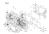
- the imaging unit 10 is provided with a body module 11, a first lens-group unit 12, a board module 13, a front cover 14 and a rear cover 15.
- the body module 11 is provided with a housing (support member/ frame body) 16 made of synthetic resin, and the second lens group G2, the third lens group G3 and the second prism L12 that constitute elements of the imaging optical system are held by the housing 16 therein.
- the housing 16 is a box-shaped member which is elongated in the leftward/rightward direction and small in thickness (slim) in the forward/rearward direction.
- the housing 16 is provided at the left end thereof with a mounting recess 17.
- the housing 16 is provided, on the front side thereof in a section positioned on the right side of the mounting recess 17, with an accommodating recess (internal space) 18 that is substantially rectangular in cross sectional shape.
- the housing 16 is provided between the mounting recess 17 and the accommodating recess 18 with a partition wall 19.
- the housing 16 is provided at a center of the partition wall 19 with a communication hole (through-hole) 20, via which the mounting recess 17 and the accommodating recess 18 are communicatively connected with each other.
- the housing 16 is provided, on the right side of the accommodating recess 18, with a positioning recess 22 having a substantially rectangular shape, in a front view.
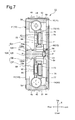
- the positioning recess 22 is positioned at a forward position with respect to the base surface of the accommodating recess 18 (see FIG. 6 ).
- a packing 23 made of an elastically deformable material is positioned in the positioning recess 22 and supported thereby.
- the packing 23 is in the shape of a rectangular frame which is fitted into the positioning recess 22.
- the packing 23 is provided at the bottom (in the base) thereof with a through-hole 24.
- the housing 16 is provided in the positioning recess 22 with a prism mounting recess 25 which is open at the front and left sides.
- the housing 16 is provided, around the front edge of the inner peripheral surface of the accommodating recess 18, with a board support surface 27 which is positioned at a rearward position with respect to the frontmost end of the housing 16 and lies in a plane orthogonal to the forward/rearward direction.
- the housing 16 is further provided, on the board support surface 27 at two different positions thereon, with two lock projections 28, respectively, which project forward from the board support surface 27.
- the housing 16 is provided on each of the upper and lower sides thereof with three engaging recesses 29A, 29B and 29C and two engaging projections 30 and 31.
- the housing 16 is further provided on the right side thereof with an upper and lower pair of engaging projections 32 (see FIG. 5 ) and an engaging projection 33 (see FIG. 6 ).
- the second prism L12 is fit-engaged into the prism mounting recess 25 and fixed thereto.
- the second prism L12 is provided with an incident surface L12-a, an exit surface L12-b and the reflecting surface L12-c.
- the incident surface L12-a is positioned on the second optical axis 02 and faces leftward
- the exit surface L12-b is positioned on the third optical axis 03 and faces forward
- the reflecting surface L12-a is angled at substantially 45 degrees with respect to the incident surface L12-a and the exit surface L12-b.
- the second lens group G2 and the third lens group G3 are supported to be positioned on the second optical axis 02 on the left-hand side of the incident surface L12-a of the second prism L12.
- the body module 11 is provided with a first rod 36 and a second rod 37, each of which is made of metal and extends linearly in the leftward/rightward direction.
- the first rod 36 and the second rod 37 are each fixed at both ends thereof to an inner surface of the right side wall of the housing 16 and the partition wall 19 so that the first rod 36 and the second rod 37 are aligned in the upward/downward direction.
- the fourth lens element L4 and the fifth lens element L5, which constitute the second lens group G2 are fit-engaged into and fixed to a lens holding hole formed through the second lens group frame 34 in the leftward/rightward direction. Additionally, a nut holding portion 34a (see FIG.
- the body module 11 is provided with a first motor M1 (see FIG. 5 ) which is fixed to the housing 16 in an upper part of the prism mounting recess 25.
- the first motor M1 is a stepping motor.
- the first motor M1 is provided with a rotary drive shaft M1a which extends linearly leftwards, and a male thread formed on the rotary drive shaft M1a is screw-engaged with the female screw hole of the driven nut 38. Accordingly, forward and reverse rotations of the rotary drive shaft M1a of the first motor M1 cause the second lens group frame 34 (the second lens group G2) to move linearly in the leftward/rightward direction along the first rod 36 and the second rod 37.
- a through-hole formed through a lower part of a third lens group frame 35 made of synthetic resin and positioned on the right-hand side of the second lens group frame 34 is fitted onto the second rod 37, while a rotation stop groove formed on an upper end of the third lens group frame 35 is engaged with the first rod 36, and accordingly, the third lens group frame 35 is slidable in the leftward/rightward direction along the first rod 36 and the second rod 37 (while being prevented from rotating about the second rod 37).
- the sixth lens element L6, which constitutes an element of the third lens group G3 is fit-engaged into and fixed to a lens holding hole formed through the third lens group frame 35 in the leftward/rightward direction, a nut holding portion 35a (see FIG.
- the body module 11 is provided with a second motor M2 (see FIG. 5 ) which is fixed to the housing 16 in a lower part of the prism mounting recess 25.
- the second motor M2 is a stepping motor which is identical in specifications to the first motor M1.
- the second motor M2 is provided with a rotary drive shaft M2a (identical in specifications to the rotary drive shaft M1a) which extends linearly leftwards, and a male thread formed on the rotary drive shaft M2a is screw-engaged with the female screw hole of the driven nut 39. Accordingly, forward and reverse rotations of the rotary drive shaft M2a of the second motor M2 cause the third lens group frame 39 (the third lens group G3) to move linearly in the leftward/rightward direction along the first rod 36 and the second rod 37.
- the body module 11 is provided with a light shield frame 120 and a light shield frame 121 which are slidably supported by the first rod 36 and the second rod 37, respectively.
- the light shield frames 120 and 121 are positioned between the third lens group frame 35 (the third lens group G3) and the prism mounting recess 25 (the second prism L12), the body module 11 is provided between the light shield frame 120 and the second lens group frame 34 with a compression coil spring 122 which enables the light shield frame 120 to be held at a proper position in the slidable direction thereof, and the body module 11 is provided between the light shield frame 121 and the third lens group frame 35 with a compression coil spring 123 which enables the light shield frame 121 to be held at a proper position in the slidable direction thereof.
- Each of the light shield frames 120 and 121 is provided at a center thereof with a rectangular aperture, which extends therethrough in the leftward/rightward direction, and is further provided with a frame portion which surrounds the rectangular aperture.
- the rectangular apertures of the light shield frames 120 and 121 allow the light rays traveling from the third lens group G3 (the sixth lens element L6) to the second prism L12 to pass through the light shield frames 120 and 121, while the frame portions of the light shield frames 120 and 121 shield unwanted light.
- the first lens-group unit 12 is provided with a first lens frame (movable frame) 40 which holds the first lens element L1 and a base frame (support member/support frame) 41 which holds the first prism L11, the second lens element L2 and the third lens element L3.
- the base frame 41 is provided with a prism mounting recess 42 which is open at the front and left sides, and the first prism L11 is fit-engaged into the prism mounting recess 42 and fixed thereto.
- the first prism L11 is provided with the incident surface L11-a, the exit surface L11-b and the reflecting surface L11-c as described above.
- the incident surface L11-a is positioned on the first optical axis O1 and faces forward
- the exit surface L11-b is positioned on the second optical axis 02 and faces rightward
- the reflecting surface L11-c is positioned at a substantially 45 degree angle with respect to the incident surface L11-a and the exit surface L11-b.
- the base frame 41 is further provided with a lens holding portion 43 which extends through the base frame 41 in the rightward direction from the prism mounting recess 42, and the second lens element L2 and the third lens element L3 are fit-engaged into the lens holding portion 43.
- the base frame 41 is provided with a pair of flanges 44 which project upward and downward, respectively.
- Each flange 44 is in the shape of a letter L (or an inverted L) in a front view as shown in FIG. 5 .
- a screw insertion hole 45 extends in the leftward/rightward direction through a wall (vertical wall) of each flange 44 which extends in the upward/downward direction.
- An engaging projection 46 is provided on, and projects from, an outer surface of a wall (horizontal wall) of each flange 44 on a part thereof that extends in the leftward/rightward direction.
- each flange 44 the right side of the vertical wall of the flange 44, through which the screw insertion hole 45 is open, is formed as a flat spacer holding surface 47, and a screw seat 48 which surrounds the screw insertion hole 45 is formed on the left side of the vertical wall of the flange 44, which is on the opposite side of the flange 44 from the spacer holding surface 47.
- the base frame 41 is provided, on the left end thereof, with an upper and lower pair of outer walls 49.
- the base frame 41 is provided in the vicinity of the upper and lower pair of outer walls 49 with an upper and lower pair of anti-shake sensor support portions 55 and 56, respectively (see FIGS. 3 and 7 ).
- Each of the anti-shake sensor support portions 55 and 56 is in the shape of a substantially rectangular recess which faces toward the rear of the base frame 41 (leftward with respect to FIG. 7 ).
- a portion of the base frame 41 from the pair of flanges 44 rightward has a shape that enables the portion of the base frame 41 to be fitted into the mounting recess 17.
- the left ends of the first rod 36 and the second rod 37 project leftward from the partition wall 19 of the housing 16 (a state where the left end of the first rod 36 projects leftward from the partition wall 19 is shown in FIG. 2 ).
- the left ends of the first rod 36 and the second rod 37 that project from the partition wall 19 are inserted into positioning holes (not shown) formed in the base frame 41 to thereby fix the positions of the base frame 41 in the forward/rearward direction and the upward/downward direction.
- the lens holding portion 43 of the base frame 41 is fitted into the communication hole 20 of the partition wall 19 of the housing 16, and the exit surface of the third lens element L3 that constitutes an element of the first lens group G1 faces the incident surface of the fourth lens element L4 that constitutes an element of the second lens group G2.
- a pair of flange support seats 50 are formed on the housing 16 at positions immediately above and below the mounting recess 17, respectively, and a screw hole 51 is formed in each flange support seat 50 so that the axis of the screw hole 51 extends in the leftward/rightward direction.
- the pair of flange support seats 50 face the spacer holding surfaces 47 of the pair of flanges 44 of the base frame 41, and the position of the base frame 41 relative to the housing 16 in the leftward/rightward direction is determined by the distance between the spacer holding surfaces 47 of the pair of flanges 44 and the pair of flange support seats 50.
- a pair of spacers 52 for adjustment of the aforementioned distance are installed and held between the pair of flanges 44 (the spacer holding surfaces 47) and the pair of flange support seats 50, respectively.
- Each spacer 52 is in the shape of a rectangular plate and is provided with a screw insertion groove 53 which is formed (recessed) toward the center of the spacer 52 from one side thereof.
- Various types of spacers 52 having different thicknesses are prepared in advance, and a pair of spacers 52 having an appropriate thickness are selected from these spacers 52 and inserted in between the spacer holding surfaces 47 of the pair of flanges 44 and the pair of flange support seats 50.
- the relative position between the first lens group G1 and the second lens group G2 in a direction along the second optical axis 02 can be changed by changing the thickness of each spacer 52 (by replacing each spacer 52 by another spacer 52 having a different thickness). More specifically, the distance between the third lens element L3 and the fourth lens element L4 is changed.
- the effect of flange back adjustment on the entire imaging optical system is obtained by a change in the position of the first lens group G1, which has a predetermined refractive power, in the optical axis direction.
- the imaging unit 10 is provided with an anti-shake (image shake correction/image-stabilizing) system that reduces image shake on an image plane which is caused by vibrations such as hand shake.
- This anti-shake system drives the first lens element L1 of the first lens group G1 in a plane orthogonal to the first optical axis O1, more specifically, the anti-shake system drives the first lens frame 40 relative to the base frame 41 in this orthogonal plane.
- the base frame 41 is provided around the prism mounting recess 42 with two movement limit projections (movement limiter) 60 which project forwardly and three ball support holes 61, which are bottomed holes that are open toward the front.
- the three ball support holes 61 are arranged at substantially equi-intervals in a circumferential direction about the first optical axis O1.
- the base frame 41 is further provided with three spring hook projections 62.
- the first lens frame 40 is provided with a cylindrical lens holding portion 63 and provided, at different positions around the lens holding portion 63 with three flanges 64, respectively, which project radially outwards.
- Three ball contact surfaces 66 are formed on the rear surfaces of the flanges 64, respectively, and three guide balls (anti-shake guide members) 67 are held between the ball contact surfaces 66 and the bottom surfaces of the ball support holes 61, respectively.
- the ball contact surfaces 66 are flat surfaces substantially orthogonal to the first optical axis O1.
- the guide balls 67 are loosely fitted into the ball support holes 61, respectively. When positioned in the vicinity of the center of the associated support hole 61, each guide ball 67 does not come in contact with the inner wall of the associated ball support hole 61.
- the first lens frame 40 is provided, at different circumferential positions on the outer periphery thereof, with three spring hook projections 68, respectively, and three extension springs 69 are extended and installed between the spring hook projections 68 and the spring hook projections 62 that are formed on the base 41, respectively.
- the first lens frame 40 is biased in a direction to approach the base frame 41 (i.e., is biased rearward) by the biasing force of the extension springs 69 to make the ball contact surfaces 66 press against the guide balls 67, respectively, to thereby prevent the first lens frame 40 from moving rearward.
- the ball contact surfaces 66 are in point contact with the guide balls 67, respectively, and the first lens frame 40 can move in directions orthogonal to the first optical axis O1 by making the ball contact surfaces 66 slidingly contact the guide balls 67 (or while making the guide balls 67 roll when the guide balls 67 are not in contact with the inner walls of the ball support holes 61, respectively).
- the prism mounting recess 42, the flanges 44 and the outer walls 49 of the base frame 41 are formed to have shapes so as not to interfere with the movement of the first lens frame 40.
- the first lens frame 40 is further provided with two movement limit holes 70 into which the movement limit projections 60 of the base frame 41 are inserted, respectively.
- the inner wall of each movement limit hole 70 is rectangular, generally square in shape in a plane substantially orthogonal to the first optical axis O1.
- the direction of one of the two diagonal lines across the inner wall of each movement limit hole 70 in a plane orthogonal to the first optical axis O1 refers to the X-axis direction and the direction of the other diagonal line refers to the Y-axis direction.
- the X-axis direction generally coincides with the upward/downward direction of the imaging unit 10
- the Y-axis direction generally coincides with the leftward/rightward direction of the imaging unit 10.
- the first lens frame 40 can move relative to the base frame 41 in a plane orthogonal to the first optical axis O1 within a range until the movement limit projections 60 come into contact with the inner walls of the movement limit holes 70, respectively.
- the first lens frame 40 is driven by an electromagnetic actuator.
- This electromagnetic actuator is provided with two permanent magnets (elements of a driver) 71 and 72 which are supported by the first lens frame 40 and two coils (elements of the driver) 74 and 75 which are supported by a circuit board 73 of the board module 13.
- the permanent magnets 71 and 72 are fixed to magnet holding portions 76 and 77, respectively, which are provided on the first lens frame 40.
- the rear surfaces of the magnet holding portions 76 and 77 are shaped to superpose the front surfaces of the anti-shake sensor support portions 55 and 56 of the base frame 41, respectively, with the first lens frame 40 and the base frame 41 combined (see FIG. 7 ).
- the permanent magnets 71 and 72 are substantially identical in shape and size to each other.
- Each of the permanent magnets 71 and 72 is in the shape of a narrow, thin rectangular plate.
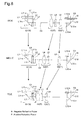
- the permanent magnets 71 and 72 are arranged symmetrically with respect to the imaginary plane P (see FIGS. 4 , 5 and 7 ) in which the first optical axis O1, the second optical axis 02 and the third optical axis 03 lie. More specifically, opposite sides of a magnetic pole boundary line Q1 (see FIG. 5 ) of the permanent magnet 71, which extends in the lengthwise direction thereof and passes through an approximate center of the permanent magnet 71 with respect to the width thereof, are magnetized into north and south poles, respectively, while opposite sides of a magnetic pole boundary line Q2 (see FIG.
- the magnetic pole boundary line Q1 defines a boundary between north and south poles of the permanent magnet 71
- the magnetic pole boundary line Q2 defines a boundary between north and south poles of the permanent magnet 72.
- the magnetic pole boundary line Q1 of the permanent magnet 71 and the magnetic pole boundary line Q2 of the permanent magnet 72 are inclined to each other so that the distance therebetween (i.e., the distance from the imaginary plane P) gradually increases in a direction from left to right.
- the inclination angles of the magnetic pole boundaries line Q1 and Q2 of the permanent magnets 71 and 72 with respect to the imaginary plane P are set to approximately ⁇ 45 degrees, respectively. Namely, the lengthwise directions (the magnetic pole boundary lines Q1 and Q2) of the permanent magnets 71 and 72 are substantially orthogonal to each other. Since the set screws 54 which fix the base frame 41 to the housing 16 are positioned in the vicinity of the permanent magnets 71 and 72, each set screw 54 is made of a nonmetal such as resin or a nonmagnetic (magnetically non-attracted) metal so that no influence is exerted on the anti-shake driving operation of the electromagnetic actuator.
- the board module 13 is provided with a circuit board 73 made of a flat plate, the front shape thereof corresponding to the front shape of a combination of the accommodating recess 18 of the housing 16 and the first lens-group unit 12.
- the circuit board 73 lies in a plane orthogonal to the forward/rearward direction.
- a printed circuit is formed on the rear surface of the circuit board 73 and connected to a flexible wiring board FL which extends rightward from the circuit board 73.
- the image sensor IS is fixed to the rear of the circuit board 73 at a position in the vicinity of the right end thereof, and a plurality of terminals (not shown) provided on the image sensor IS are fixedly connected to the printed circuit by soldering.
- the surface of the image sensor IS which faces rearwardly is formed as an imaging surface, the entire surface of which is covered by a cover glass.
- the image sensor IS and the cover glass are shown as a single body.
- the circuit board 73 is provided, in the vicinity of two diagonally opposite corners thereof, with two circular holes 80, respectively.
- the circuit board 73 is further provided in the vicinity of the left end thereof with a photographing aperture 81 which is formed through the circuit board 73 in the forward/rearward direction.
- each of the coils 74 and 75 is an air-core coil which includes a pair of elongated portions that are substantially parallel to each other and a pair of curved (U-shaped) portions which connect the pair of elongated portions at the respective ends thereof.
- the coils 74 and 75 are substantially identical in shape and size to each other.
- the circuit board 73 is further provided at the left end thereof with two sensor support arms 82 and 83. Each of the two sensor support arms 82 and 83 firstly projects rearward and subsequently bends to extend substantially parallel to a plane in which the circuit board 73 lies.
- An anti-shake sensor 84 is supported by the sensor support arm 82 on the front surface thereof and faces the rear of the coil 74.
- An anti-shake sensor 85 is supported by the sensor support arm 83 on the front surface thereof and faces the rear of the coil 75.
- the board module 13 is mounted to the body module 11 (the housing 16), to which the first lens-group unit 12 is mounted.
- the front opening of the accommodating recess 18 is closed to make an outer peripheral portion of the rear surface of the circuit board 73 come in contact with the board support surface 27 with the circular holes 80 of the circuit board 73 respectively fitted on the engaging projections 28 of the housing 16 (the front surfaces of the circuit board 73 and the housing 16 substantially lie in a plane).
- the image sensor IS cover glass comes into contact with the packing 23 as shown in FIG. 6 , so that the periphery of the imaging surface of the image sensor IS is sealed up by the packing 23.
- the optical path between the exit surface L12-b of the second prism L12 and the image sensor IS is secured via the through-hole 24 of the packing 23.
- the first lens element L1 is exposed forward through the photographing aperture 81 of the circuit board 73, and the first lens frame 40 is prevented from coming off forward by a plate surface of the circuit board 73 around the photographing aperture 81.
- the lengthwise direction of the coil 74 is substantially parallel to the magnetic pole boundary line Q1 of the permanent magnet 71 and the lengthwise direction of the coil 75 is substantially parallel to the magnetic pole boundary line Q2 of the permanent magnet 72.
- the coils 74 and 75 are connected to the printed circuit formed on the rear surface of the circuit board 73.
- the control of power that is applied to the coils 74 and 75 is performed by a control circuit (not shown).
- a driving force is generated in a direction substantially orthogonal to the magnetic pole boundary line Q1 of the permanent magnet 71 (i.e., orthogonal to the lengthwise direction of the coil 74) in a plane orthogonal to the optical axis O upon the coil 74 being energized.
- this driving force is shown by a double-headed arrow F1 in FIGS. 4 and 5 .
- a driving force is generated in a direction substantially orthogonal to the magnetic pole boundary line Q2 of the permanent magnet 72 (i.e., orthogonal to the lengthwise direction of the coil 75) in a plane orthogonal to the optical axis O upon the coil 75 being energized.
- the direction of action of this driving force is shown by a double-headed arrow F2 in FIGS. 4 and 5 .
- each of the two aforementioned driving forces intersects both the X-axis direction and the Y-axis direction at an angle of approximately 45 degrees, so that the first lens frame 40 can be moved to any arbitrary position in a plane orthogonal to the first optical axis O1 with respect to the base frame 41 (and the body module 11 and the board module 13 that are fixed with respect to the base frame 41) by controlling the passage of current through each of the coils 74 and 75.
- the moving range of the first lens frame 40 is limited by engagement of the inner walls of the two movement limit holes 70 with the two movement limit projections 60, respectively.
- Each of the two anti-shake sensors 84 and 85 is a magnetic sensor (Hall sensor) and connected to the aforementioned printed circuit that is formed on the rear surface of the circuit board 73.
- the anti-shake sensor 84 enters the anti-shake sensor support portion 55 of the base frame 41 from the rear side to be positioned behind the permanent magnet 71
- the anti-shake sensor 85 enters the anti-shake sensor support portion 56 of the base frame 41 from rear to be positioned behind the permanent magnet 72.
- Variation in position of the permanent magnet 71 in accordance with movement of the first lens frame 40 that is caused by the electromagnetic actuator causes the output of the anti-shake sensor 84 to vary
- variation in position of the permanent magnet 72 in accordance with movement of the first lens frame 40 that is caused by the electromagnetic actuator causes the output of the anti-shake sensor 85 to vary
- the position of the first lens frame 40 can be detected from the output variations of the two anti-shake sensors 84 and 85.
- the front cover 14 is a press-molded sheet metal product and is integrally provided with a base 90, an upper and lower pair of engaging lugs 91, an upper and lower pair of engaging lugs 92 and an upper and lower pair of side engaging lugs 93.
- the base 90 is formed as a planar member orthogonal to the forward/rearward direction.
- the upper engaging lug 91 and the upper engaging lug 92 extend rearward from the upper edge of the base 90, and the lower engaging lug 91 and the lower engaging lug 92 extend rearward from the lower edge of the base 90.
- the pair of side engaging lugs 93 extend rearward from the right edge of the base 90.
- a rectangular engaging hole 91a, a rectangular engaging hole 92a and a rectangular engaging hole 93a are formed through each of the upper and lower engaging lugs 91, each of the upper and lower engaging lugs 92 and each of the side engaging lugs 93, respectively.
- the base 90 is provided at the right end thereof with three pressure leaves 94 each of which is resiliently deformable in the forward/rearward direction.
- Each pressure leaf 94 in a free state lies in a plane in which the other part of the base 90 lies.
- Each pressure leaf 94 is provided in the vicinity of the free end thereof with a pressure projection 94a which projects rearward.
- the base 90 is provided in the vicinity of the left end thereof with a photographing aperture 95 which is formed therethrough in the forward/rearward direction.
- the rear cover 15 is a press-molded sheet metal product and is integrally provided with a base 100, an upper and lower pair of engaging lugs 101, an upper and lower pair of engaging lugs 102, a side engaging lug 103 and a support lug 104.
- the base 100 is formed as a planar member orthogonal to the forward/rearward direction.
- the upper engaging lug 101 and the upper engaging lug 102 extend forward from the upper edge of the base 100, and the lower engaging lug 101 and the lower engaging lug 102 extend forward from the lower edge of the base 100.
- the side engaging lug 103 extends forward from the right edge of the base 100, and the support lug 104 projects from the left end of the base 100.
- a rectangular engaging hole 101a is formed through each of the upper and lower engaging lugs 101, and a rectangular engaging hole 103a is formed through the side engaging lug 103.
- the support lug 104 is provided with a base portion 105, a pair of upright walls 106 and a pair of sensor support walls 107.
- the base portion 105 is continuous with and projects leftward from the base 100, the pair of upright walls 106 project forward from the upper and lower ends of the base portion 105, respectively, and the pair of sensor support walls 107 extend vertically in opposite directions away from each other from the front edges of the pair of upright walls 106, respectively.
- An engaging hole 106a is formed through each upright wall 106.
- the base frame 41 that constitutes an element of the first lens-group unit 12 is provided with a support protrusion 78 which projects rearward to be fit-engaged into a portion (recessed portion) of the support lug 104 which is surrounded by the base portion 105 and the pair of upright walls 106.
- the support protrusion 78 is provided on upper and lower sides thereof with two (upper and lower) engaging projections 78a, respectively, which are engaged with the engaging holes 106a of the pair of upright walls 106, respectively.
- the front cover 14 is mounted to the front of the board module 13 with a rectangular light shielding sheet 108 held between the front cover 14 and the front of the board module 13.
- the light shielding sheet 108 can be omitted if sufficient light-tightness can be ensured without the light shielding sheet 108.
- the front cover 14 is fixed to the housing 16 by making the base 90 cover the circuit board 73 from front while engaging the upper and lower engaging lugs 91 with the upper and lower engaging recesses 29A of the housing 16, respectively, engaging the upper and lower engaging holes 91a of the upper and lower engaging lugs 91 with the upper and lower engaging projections 30 of the housing 16, respectively, and engaging the engaging holes 93a of the upper and lower side engaging lugs 93 with the upper and lower engaging projections 32 of the housing 16, respectively.
- the front cover 14 is fixed to the base frame 41 by engaging the engaging holes 92a of the upper and lower engaging lugs 92 with the upper and lower engaging projections 46 of the base frame 41 while sliding the upper and lower engaging lugs 92 on the upper surface of the upper flange 44 and the lower surface of the lower flange 44, respectively.
- each pressure leaf 94 Upon the front cover 14 fixed to the housing 16, the pressure projection 94a of each pressure leaf 94 comes into contact with a front surface of the circuit board 73 and thereupon a rearward pressing force (biasing force) acts on the front surface of the circuit board 73 from the pressure leaves 94 resiliently deformed slightly forwards, so that the circuit board 73 (the board module 13) is precisely positioned and held at a predetermined position in the forward/rearward direction relative to the housing 16 (the body module 11).
- biasing force biasing force
- the photographing aperture 95 that is formed in the front cover 14 is formed to correspond in position and shape to the photographing aperture 81 of the circuit board 73, so that the photographing aperture 95 is communicatively connected to the photographing aperture 81 and so that the first lens element L1 is exposed toward the front of the imaging unit 10 through the photographing apertures 81 and 95 in a state where the front cover 14 is mounted to the front of the board module 13.
- the rear cover 15 is mounted to the rear sides of the body module 11 and the first lens-group unit 12.
- the rear cover 15 is fixed to the housing 16 by making the base 100 cover the rear side of the housing 16 while engaging each of the upper and lower engaging lugs 101 and each of the upper and lower engaging lugs 102 with the associated engaging recess 29B and the associated engaging recess 29C of the housing 16, respectively, engaging the engaging hole 101a of each engaging lug 101 with the associated engaging projection 31 of the housing 16, and engaging the engaging hole 103a of the side engaging lug 103 of the rear cover 15 with the engaging projection 33 (see FIG. 6 ) that is formed on the right side of the housing 16. Additionally, as shown in FIG.
- the rear cover 15 is fixed to the base frame 41 by making the base 100 of the rear cover 15 cover the base frame 41 from rear while engaging the support protrusion 78 of the base frame 41 in the recessed portion of the support lug 104 of the rear cover 15 that is formed by the base portion 105 and the pair of upright walls 106 of the support lug 104 of the rear cover 15, and engaging the upper and lower engaging projections 78a of the support protrusion 78 in the upper and lower engaging holes 106a, respectively.
- the pair of sensor support walls 107 face the rear surfaces of the sensor support arms 82 and 83 of the circuit board 73 to prevent the sensor support arms 82 and 83 from being deformed rearward.
- the upper and lower sensor support walls 107 are resiliently deformed to press the sensor support arms 82 and 83 lightly forward to hold the anti-shake sensors 84 and 85 in the anti-shake sensor support portions 55 and 56, respectively. With this structure, each of the anti-shake sensors 84 and 85 is precisely held at a predetermined position.
- the imaging unit 10 that is completely assembled as described above is directed toward an object located in front of the imaging unit 10, light reflected by the object (light emanating from a photographic object) enters the first prism L11 through the incident surface L11-a after passing through the first lens element L1 and is reflected at an angle of 90 degrees by the reflecting surface L11-c of the first prism L11 to travel toward the exit surface L11-b.
- the reflected light that emerges from the exit surface L11-b of the first prism L11 enters the second prism L12 from the incident surface L12-a after passing through the lens elements L2 through L6, and is reflected at an angle of 90 degrees by the reflecting surface L12-c of the second prism L12 to travel toward the exit surface L12-b. Subsequently, the reflected light that emerges from the exit surface L12-b is captured (received) by the imaging surface of the image sensor IS.
- a zooming operation of the imaging optical system is performed by moving the second lens group G2 (the lens elements L4 and L5) and the third lens group G3 (the lens element L6) along the first rod 36 and the second rod 37 using the first motor M1 and the second motor M2.
- a focusing operation of the imaging optical system is performed by moving the third lens group G3 (the lens element L6) along the first rod 36 and the second rod 37 using the second motor M2.
- FIG. 8 shows different states of the imaging optical system set at the wide-angle extremity, an intermediate focal length, and the telephoto extremity.
- the positions of the first lens group G1, the second prism L12 and the image sensor IS do not vary while the distance (the distance in a direction along the second optical axis 02) between the first lens group G1 and the second lens group G2 gradually decreases.
- the distance between the second lens group G2 and the third lens group G3 increases from the wide-angle extremity to the intermediate focal length and decreases from the intermediate focal length to the telephoto-extremity.
- an anti-shake (image shake correction/ image-stabilizing) operation is performed using the first lens element L1 of the first lens group G1 that is positioned in front of the first prism L11.
- the anti-shake system supports the first lens frame 40 in a manner to allow the first lens frame 40 to move relative to the base frame 41, which is fixed with respect to the housing 16, in a plane orthogonal to the first optical axis O1 and drives the first lens frame 40 using the electromagnetic actuator.
- the first lens frame 40 is located on the front side of the imaging unit 10 in the vicinity of the left end thereof.
- the housing 16 is formed to create a predetermined space (clearance) between the housing 16 and the first lens frame 40 to prevent the partition wall 19 and the flange support seat 50 from interfering with the first lens frame 40 even when the first lens frame 40 moves within the moving range defined by the anti-shake system.
- the incident surface of the first lens element L1 is substantially flush with the front surface of the base 90 of the front cover 14, with the lens holding portion 63 of the first lens frame 40 inserted into the photographing aperture 81 of the circuit board 73 and the photographing aperture 95 of the front cover 14 as shown in FIG.
- each photographing aperture 81 and 95 is also set so as not to interfere with the first lens frame 40 even when the first lens frame 40 moves within the moving range defined by the anti-shake system. Accordingly, the first lens frame 40 can reliably be made to perform an anti-shake operation without any interference from any other elements of the imaging unit 10.
- the moving direction of the first lens element L1 during an anti-shake operation is orthogonal to the first optical axis O1. Accordingly, the first lens frame 40 that holds the first lens element L1 does not move in the forward/rearward direction that corresponds to the direction of the thickness of the imaging unit 10.
- the support mechanism (which is configured of the movement limit projections 60, the ball support holes 61, the ball contact surfaces 66, the guide balls 67, the movement limit holes 70) and the driver (the permanent magnets 71 and 72, the coils 74 and 75) that are for moving the first lens frame 40 relative to the base frame 41 are arranged at positions about the first optical axis O1 which surround the first lens element L1, so that the installation space for the support mechanism and the driver can be small with respect to the forward/rearward direction of the imaging unit 10. Accordingly, the selection of the first lens element L1 as an anti-shake optical element makes it possible to slim down the imaging unit 10 while providing the imaging unit 10 with an anti-shake system.
- the first lens element L1 that supports the first lens frame 40 does not need to be connected to the circuit board 73, unlike an electrical component such as the imaging sensor IS, so that the supporting structure for the first lens frame 40 does not become complicated by routing of a flexible wiring board, or a flexible wiring board does not exert resistance on the first lens element L1 during an anti-shake operation.
- the image sensor IS and the circuit board 73 would be connected to each other via a flexible wiring board after the image sensor IS is supported by the circuit board 73.
- the flexible wiring board is required to have a sufficient length so as not to provide resistance to movement of the image sensor IS; however, there is not much space around the image sensor IS, so that the flexible wiring board would interfere with other members if the flexible wiring board is made long. To prevent this problem from occurring, if the image sensor IS and the circuit board 73 are spaced from each other in the forward/rearward direction, this spacing becomes in conflict with the slimming down of the imaging unit 10.
- the selection of the front lens element(s), corresponding to the first lens element L1, as an anti-shake optical element avoids the above described problems and makes it possible to achieve a simple anti-shake system which contributes to the slimming down of the imaging unit 10. Since only the front lens element (s) that is positioned on the object side of the first prism L11 is driven during the anti-shake control, rather than the entire first lens group G1, there is the advantage that the moving parts of the anti-shake system can be made compact and the driving load thereon can be small.
- the anti-shake optical element is not limited to one lens element
- the present invention can also be applied to a configuration in which a plurality of lens elements (anti-shake optical elements) provided on the object side of the first prism L11 are driven to perform anti-shake control. Therefore, although the description hereinbelow describes a configuration in which only the first lens element L1 is described as the first lens element L1, a configuration in which a plurality of lens elements are driven (moved) to perform anti-shake control is also applicable by replacing the term "first lens element L1" with "front lens elements".
- the first prism L11 that operates only to reflect the incident light rays is disposed between the front lens element (first lens element L1) used for anti-shake operation and the second lens element L2 (that are optical elements having refractive power) in the first lens group G1 in the present embodiment, the distance between the front lens element (first lens element L1) and the second lens element L2 is great, so that the deterioration in aberration is small even if the front lens element (first lens element L1) is solely moved to perform anti-shake control.
- first lens element L1 and the second lens element L2 which are spaced far from each other in the optical axis direction with the first prism L11 positioned therebetween, are treated as different lens groups, even though the aberration is controlled over the entire first lens group G1, which extends from the front lens element (first lens element L1) to the third lens element L3, as a part of a zoom lens system; hence, only the front lens element that is positioned on the object side of the first prism L11 is set as an optical element used for anti-shake operation in the present embodiment.
- the length in an optical axis direction (the distance between the image plane and the lens element closest to the object side) varies when a zooming operation or a barrel retracting operation is performed
- the length of the optical path from the incident surface of the front lens element (first lens element L1) to the image plane (the imaging surface of the image sensor IS) in the imaging unit 10 is constant at all times. Therefore, it is possible to embed the imaging unit 10 into a mobile electronic device and cover the front of the front lens element (first lens element L1) with a protection glass or the like, and no practical problem arises even if the front lens element (first lens element L1), of the optical system of the imaging unit 10, that is located closest to the object side is driven to cancel out image shake.
- optical conditions will be hereinafter described based on a configuration in which only one first lens element L1 is provided in front (on the object side) of the first prism L11, however the optical conditions are also applicable to a configuration in which a plurality of lens elements (anti-shake optical elements/first lens elements L1) are provided in front (on the object side) of the first prism L11, as mentioned above.
- first lens element L1 and the first prism L11 it is required to secure a sufficient distance (amount of clearance) between the first lens element L1 and the first prism L11 to prevent the first lens element L1 and the first prism L11 (or the first lens frame 40 and the base frame 41) from interfering with each other when the first lens element L1 is moved in directions orthogonal to the first optical axis O1.
- the distance between the first lens element L1 and the first prism L11 is made excessively large, the size of the imaging unit 10 in the direction of the thickness thereof (the forward/rearward direction) becomes great. Accordingly, it is required to determine the distance between the first lens element L1 and the first prism L11 while taking the balance between this distance and the size of the imaging unit 10 into account.
- the first lens element L1 is provided with an incident surface L1-a which faces the object side and a concave surface L1-b, constituting an exit surface, which is located on the image plane side.
- the concave surface L1-b is an effective optical surface of the first lens element L1 that is located on the image surface side, and the first lens element L1 is provided around the concave surface L1-b with a rim L1-c.
- a rear end surface L1-d of the rim L1-c is a portion of the first lens element L1 which is the closest to the incident surface L11-a of the first prism L11.
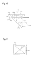
- the rear end surface L1-d of the first lens element L1 is a flat surface which lies in a plane substantially orthogonal to the first optical axis O1. It is desirable that the following condition (1) be satisfied: 1 ⁇ D / S ⁇ 1 ⁇ 10
- D designates the distance between the rear end surface L1-d and the incident surface L11-a in the direction along the first optical axis O1 (see FIG. 10 )
- S1 designates the amount of movement of the first lens element L1 when the shake correction angle is 0.5 degrees.
- the amount of movement of the first lens element L1 when the shake correction angle is 0.5 degrees is determined by the focal length of the first lens element L1. Since the focal length of the first lens element L1 is determined according to the overall structure of the imaging optical system, the focal length of the first lens element L1 results in being selectively determined based on the balance between the focal length of the first lens element L1 and the entire size of the imaging unit 10 that accommodates an imaging optical system.
- the rear end of the first lens element L1 is formed as the rear end surface L1-d that is a flat surface substantially orthogonal to the first optical axis O1 in the above illustrated embodiments, condition (1) is also effective in a structure in which the rear end of the first lens element L1 does not have such a flat surface.
- the "D" in condition (1) is the distance from the rear end of the front lens element that is provided closest to the image side (closest to the first prism L1) to the incident surface L11-a of the first prism L11.
- Table 1 shows the numerical values of the first through fourth embodiments, which satisfy condition (1): [TABLE 1] S1 [mm] D [mm] D/S1 Embod.1 0.062 0.150 2.419 Embod.2 0.075 0.236 3.147 Embod.3 0.053 0.238 4.491 Embod.4 0.091 0.281 3.088
- condition (1) it is further desirable for the condition 1 ⁇ D/S1 ⁇ 6 to be satisfied.
- the maximum amount of movement of the first lens element L1 for image shake correction is determined in consideration of the optical performance and the magnitude of the imaging unit 10. Accordingly, it is desirable for the following condition (2) to be satisfied: S / Y ⁇ 0.2 wherein S designates the maximum amount of movement of the first lens element L1 along a plane orthogonal to the first optical axis O1 (the maximum amount of movement of the first lens frame 40 that is mechanically limited by the two movement limit projections 60 and the two movement limit holes 70), and Y designates the diagonal image height on the image sensor IS.
- the diagonal image height Y denotes the length of one half of a diagonal line of the effective light receiving area IS-a of the image sensor IS.
- condition (2) If condition (2) is not satisfied, the amount of movement of the first lens element L1 during an anti-shake operation becomes excessively great, consequently exceeding a range in which deterioration of optical performance and reduction of brightness at the edge of image field are allowable. Additionally, if condition (2) is not satisfied, it is required to secure a large space for movement of the first lens element L1 because the first lens element L1 also mechanically moves, which increases the size of the imaging unit 10. If condition (2) is satisfied, optical performance does not easily deteriorate while the imaging unit 10 can be prevented from being enlarged.
- Table 2 shows the numerical values of the first through fourth embodiments, which satisfy condition (2): [TABLE 2] S [mm] Y [mm]
- the present invention can also be applied to a type of imaging optical system like an imaging unit 210 shown in FIG. 9 that includes no reflector such as a prism between a movable lens group (the second lens group G2 and the third lens group G3) and the image sensor IS.
- a sensor support space 225 is formed at a position corresponding to the position at which the prism mounting recess 25 is formed in the previous embodiment of the imaging unit 10, and the image sensor IS is installed in the sensor support space 225 so that the imaging surface of the imaging sensor IS faces leftward.
- the image sensor IS lies on the second optical axis 02, and the light rays emerging from the third lens group G3 (the sixth lens element L6) are incident on the image sensor IS without being reflected.
- the imaging unit 210 that includes such an L-shaped optical path, the above described effects are obtained by making the first lens element L1 serve as an anti-shake optical element.
- the image sensor IS is made to serve as an anti-shake optical element, the possibility of the housing 16 increasing in size in the forward/rearward direction is great, similar to the case where the second lens group G2 or the third lens group G3 is made to serve as an anti-shake optical element, and accordingly, the present invention is suitable for achieve the slimming down of the imaging unit 210 (reduction in size in the forward/rearward direction).
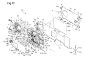
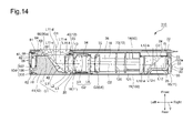
- FIGS. 12 through 14 show another embodiment of the imaging unit.
- the mechanism which makes the base frame 41 support the first lens frame 40 in a manner to allow the first lens frame 40 to move in the imaging unit 310 is different from that provided in each of the previous embodiments of the imaging units.
- the three guide balls 67 are held between the first lens frame 40 and the base frame 41 in each of the above described imaging units 10 and 210, whereas a sliding sheet 86 is held between the first lens frame 40 and the base frame 41 in the imaging unit 310. As shown in FIGS.
- a sliding projection 87 is formed on each of the three flanges 64 of the first lens frame 40 to project rearward, i.e., in a direction to approach the base frame 41 (note that only one sliding projection 87 appears in each of FIGS. 13 and 14 ).
- the rear ends of the three sliding projections 87 are formed as surfaces lying in a plane orthogonal to the first optical axis O1.
- the base frame 41 is provided, at three positions respectively facing the flanges 64 of the first lens frame 40, with three support surfaces 88 which lie in a plane orthogonal to the first optical axis O1.
- the base frame 41 is provided, on two of the three support surfaces 88 which are positioned on the vertically opposite sides of the prism mounting recess 42, with two positioning projections 89, respectively.
- the sliding sheet 86 is a thin plate member which is substantially U-shaped in a front view, including three contact portions 86a and a frame-shaped connecting portion 86b which connects the three contact portions 86a.
- the sliding sheet 86 is made of a material having a low skin friction resistance (e.g., polytetrafluoroethylene).
- the sliding sheet 86 is provided with two positioning holes 86c, in which the positioning projections 89 of the base frame 41 are engaged.
- each contact portion 86a is held between the first lens frame 40 and the base 41 by the biasing force of the extension springs 69 while being sandwiched from between the sliding projection 87 of the associated flange 64 of the first lens frame 40 and the associated support surface 88 of the base frame 41.
- the first lens frame 40 can be driven smoothly relative to the base frame 41 to reduce image shake by sandwiching the low slide-resistant sliding sheet 86 between the first lens frame 40 and the base 41, similar to the above described case using the three guide balls 67.
- the sliding sheet 86 consists of a single member including the three contact portions 86a and the frame-shaped connecting portion 86b that connects the three contact portions 86a, the number of elements is small, so that the sliding sheet 86 can be easily installed.
- the sliding sheet 86 is in the shape of a thin plate, which makes it easy to slim down the camera (reduce the size of the camera in the forward/rearward direction).
- the structure in which the sliding sheet 86 is sandwiched between the three sliding projections 87 and the three support surfaces 88 also has the advantage of not requiring the first lens frame 40 or the base frame 41 to have a complicated shape.
- the present invention has been described based on the above illustrated embodiments, the present invention is not limited solely thereto; various modifications to the above illustrated embodiments is possible.
- the base frame 41 is formed as a separate member from the housing 16 in the above illustrated embodiments of the imaging units, it is possible to provide a single support member which corresponds to a combination of the base frame 41 and the housing 16 and to make this single support member support all the optical elements except the first lens element L1.
- the first lens element L1 in the above illustrated embodiments can be replaced by two or more than two front lens elements which are arranged in front of the first prism L11.
- the distances between the front lens elements installed in front of the first prism L11 are small, and accordingly, to prevent the aberration from deteriorating it is advisable to perform anti-shake control by moving all the plurality of front lens elements that are arranged in front of the first prism L11 in directions orthogonal to the first optical axis O1.
- a lens element of the plurality of front lens elements has an extremely weak refractive power so as not to influence aberrations, a configuration is possible in which such a weak powered lens element is not moved during anti-shake control.
- the number of lens elements arranged behind the first prism L11 in the first lens group G1 can be one or more than two. Additionally, it is possible to modify the first G1 so that no lens element is provided behind the first prism L11.
- the length of the optical path from the incident surface of the first lens element L1 to the image plane in the imaging unit 10 is constant at all times in the above described embodiments.
- the first lens element L1 that is the closest to the object side is generally a negative lens.
- the lens (front lens element) for use in anti-shake control in the imaging apparatus according to the present invention can be a positive lens. Regardless of whether the power of the front lens element is negative or positive, any lens element can be adopted as the front lens as long as it has a refractive power.
- the distance from the reflector (the incident surface L11-a of the first prism L11) to the rear end of the rim or the apex of the convex surface, whichever is closest to the reflector, of such a front lens element is "D" of condition (1).
- the mechanism for mechanically determining "S" in condition (2) is not limited to the configuration described in the embodiments, alternative mechanisms, etc., are possible.
- the imaging optical system of the above illustrated embodiment of the imaging unit 10 is a zoom lens (variable power optical system) which performs a zooming operation by moving the second lens group G2 and the third lens group G3 along the second optical axis 02
- the present invention is also applicable to an imaging apparatus which incorporates an imaging optical system having no power varying capability.
- the photographing optical system in each of the above described embodiments of the imaging units uses at least one prism as a reflector that bends an optical path
- the prism can be replaced by a different type of reflector such as a mirror.
- the bending angle (reflection angle) of an optical axis by the reflector can be an angle other than 90 degrees.
- each of the above described embodiments of the imaging units can be modified to use only two extension springs 69.
- each of the above described embodiments of the imaging units can be modified so that it has no biaser like the extension springs 69.
Abstract
Description
- The present invention relates to an imaging apparatus equipped with an anti-shake (image shake correction/image stabilizing) system.
- In recent years, mobile electronic devices which are designed mainly for taking still/moving photographic images, such as digital cameras (still-video cameras) and digital camcorders (motion-video cameras), and other mobile electronic devices which are designed to be capable of taking such photographic images as a subsidiary function, such as mobile phones equipped with a camera and personal digital assistants (PDAs) equipped with a camera, have become widespread. In these types of mobile electronic devices, it is common to provide the mobile electronic device therein with an imaging unit (imaging apparatus) which is configured so that an image sensor (image pickup device) and a photographing optical system, for guiding light emanating from a photographic object (object-emanated light) to the image sensor, are accommodated in a hollow housing of the imaging unit. Additionally, in recent years, the demand to slim down this type of imaging unit has become stronger due to further progress in the slimming down of mobile electronic devices. In order to slim down an imaging unit, it is known to provide an imaging unit with a bending optical system which reflects (bends) light rays using a reflecting surface of a reflector such as a prism or a mirror.
- In addition, imaging units tend to be equipped with a so-called anti-shake (image shake correction) system that is designed to reduce image shake on an image plane that is caused by vibrations such as hand shake. The following four different types of imaging units are known in the art as imaging units using a bending optical system which are equipped with an anti-shake system: a first type (disclosed in Japanese Unexamined Patent Publication Nos.
2009-86319 2008-268700 2010-128384 4, 789, 655 2007-228005 2010-204341 2006-330439 4,717,529 2006-166202 2006-259247 - The first type of anti-shake system tends to become complicated in structure and tends to increase in cost because a circuit board connected to the image sensor is moved so as to follow movements of the image sensor, which requires electrical components around the image sensor also to be movable components in addition to the image sensor. In addition, the periphery of the imaging surface of the image sensor is required to be dust tight; however, in small imaging units intended for being incorporated into a mobile phone or a personal digital assistant, it is difficult to secure sufficient space for allowing the image sensor to perform an anti-shake (image shake correction/image-stabilizing) operation while maintaining the dust-tight structure of the image sensor.
- The second type of anti-shake system has a structure such that the moving direction of the lens group, disposed behind the reflector, during an anti-shake operation corresponds to the direction of the thickness of the imaging unit (i.e., the forward/rearward direction of the imaging unit, wherein the direction toward an object to be photographed refers to the forward (front) direction of the imaging unit), and hence, there is a problem with providing enough space to house such an anti-shake structure in a slimmed-down imaging unit. In other words, the slimming of the imaging unit is limited if this type of anti-shake system is used. There is a similar problem also in the type of anti-shake system in which an image sensor is moved, instead of a lens group, in the direction of the thickness of the imaging unit.
- The third type of anti-shake system requires a large space for allowing the reflector or the lens group to move in oblique directions, and accordingly, the imaging unit easily enlarged in size. The fourth type of anti-shake system requires a larger space for allowing the entire imaging unit to be obliquely moved to reduce image shake.
- The present invention has been devised in view of the above mentioned drawbacks and provides an imaging apparatus which can carry out image-shake correction (image stabilization) while achieving miniaturization of the imaging apparatus, especially reduction in thickness thereof.
- According to an aspect of the present invention, an imaging apparatus is provided, including a front lens group, which constitutes part of an imaging optical system of the imaging apparatus, provided at a fixed position with respect to an optical axis direction, wherein the front lens group includes at least one front lens element, and a reflector, in that order from an object side, wherein the reflector reflects light rays exiting from the front lens element; a movable lens group, which constitutes another part of the imaging optical system, provided closer to the image plane side than the front lens group and movable along the optical axis; a support member which supports at least the reflector of the front lens group; a movable frame which supports the front lens element of the front lens group and is supported by the support member to be movable along a plane orthogonal to the optical axis of the front lens element; and a driver which drives the movable frame in the plane, in accordance with vibrations applied to the photographing optical system, to reduce image shake on the image plane.
- It is desirable for the front lens group to include at least one rear lens element onto which the light rays reflected by the reflector are incident.
- Although the front lens element of the front lens group can have an arbitrary refractive power, it is desirable for the front lens element of the front lens group to have a negative refractive power.
- It is desirable for the photographing optical system to include a zoom lens system which varies a focal length thereof by moving the movable lens group in the optical axis direction.
- It is desirable for the front lens group to have a negative refractive power and for the movable lens group to include a second lens group having a positive refractive power and a third lens group having a positive refractive power, in that order from the object side.
- It is desirable for the reflector of the front lens group to include a prism.
- It is desirable for the following condition (1) to be satisfied:

wherein D designates the distance between the front lens element and the reflector in the optical axis direction, and S1 designates an amount of movement of the front lens element when a shake correction angle is 0.5 degrees. - Satisfying condition (1) makes it possible to achieve miniaturization of the imaging apparatus while providing a moderate (suitable) clearance between the front lens element and the reflector which prevents the front lens element and the reflector from interfering with each other.
- It is desirable for the support member to include a frame body having a box shape which supports the movable lens group in a manner to allow the movable lens group to move in the optical axis direction; and a support frame which fixedly supports the reflector, is fixed to the frame body, and supports the movable frame in a manner to allow the movable frame to move in the plane orthogonal to the optical axis of the front lens element.
- It is desirable for the imaging apparatus to include a second reflector which is provided between the movable lens group and the image plane and reflects light rays, exiting from the movable lens group, toward the image plane.
- It is desirable for the imaging apparatus to include an image sensor which lies on the image plane.
- It is desirable for the following condition (2) to be satisfied:
- (2) |S/Y|<0.2, wherein S designates a maximum amount of movement of the front lens element along a plane orthogonal to the optical axis, and Y designates a diagonal image height of an effective light receiving area of the image sensor.
- Satisfying condition (2) makes the optical performance of the imaging apparatus difficult to deteriorate and also makes it possible to prevent the imaging apparatus from enlarging in size.
- According to the present invention, an anti-shake operation is performed by moving the front lens element, which is located in front of the reflector of the front lens group, in directions orthogonal to an optical axis, and accordingly, miniaturization of the imaging apparatus, especially slimming down thereof in the forward/rearward direction can be efficiently achieved even though the imaging apparatus incorporates an anti-shake system.
- The present invention will be described below in detail with reference to the accompanying drawings in which:
-
FIG. 1 is a perspective view of an embodiment of an imaging unit according to the present invention; -
FIG. 2 is an exploded perspective view of the imaging unit; -
FIG. 3 is an exploded perspective view of a first lens-group unit of the imaging unit; -
FIG. 4 is a front elevational view of the imaging unit; -
FIG. 5 is a front elevational view of the imaging unit from which a front cover and a board module are removed; -
FIG. 6 is a transverse sectional view taken along the line VI-VI shown inFIG. 4 ; -
FIG. 7 is a longitudinal sectional view taken along the line VII-VII shown inFIG. 4 ; -
FIG. 8 shows sectional side elevational views of an imaging optical system provided in the imaging unit, schematically showing different states of the imaging optical system at the wide-angle extremity, an intermediate focal length and the telephoto extremity; -
FIG. 9 is a view similar to that ofFIG. 6 , showing another embodiment of the imaging unit which is not provided in the imaging optical system thereof with the second prism that the previous embodiment of the imaging unit has; -
FIG. 10 is a cross sectional view of a first lens element and a first prism that are arranged along a first optical axis and serves as elements of the imaging optical system in each of the above described embodiments of the imaging units; -
FIG. 11 is an elevational view of the image sensor shown inFIGS. 2 ,4 ,6 and9 , viewed from the light-receiving surface side; -
FIG. 12 is a view similar to that ofFIG. 2 , illustrating another embodiment of the imaging unit in which the mechanism which supports a first lens frame for the first lens element in a manner to allow the first lens frame to move is different from that provided in each of the previous embodiments of the imaging units; -
FIG. 13 is a view similar of that ofFIG. 3 , illustrating the first lens-group unit that constitutes part of the imaging unit shown inFIG. 12 ; and -
FIG. 14 is a cross sectional view, similar to those shown inFIGS. 6 and9 , of the imaging unit shown inFIG. 12 that is taken along a second optical axis. - An embodiment of an imaging unit (imaging apparatus) 10 according to the present invention will be discussed below with reference to
FIGS. 1 through 8 . In the following descriptions, forward and rearward directions, leftward and rightward directions, and upward and downward directions are determined with reference to the directions of the double-headed arrows shown in the drawings. The object side corresponds to the front side. As shown by the outward appearance of theimaging unit 10 inFIGS. 1 and4 , theimaging unit 10 has a laterally elongated shape which is slim in the forward/rearward direction and long in the leftward/rightward direction. - As shown in
FIGS. 6 and8 , theimaging unit 10 is provided with a first lens group (front lens group) G1, a second lens group (movable lens group) G2 and a third lens group (movable lens group) G3. The first lens group G1 is provided with a first prism (reflector) L11 and theimaging unit 10 is provided with a second prism (second reflector) L12 on the right-hand side of the third lens group G3, and theimaging unit 10 is configured as a bending optical system which reflects (bends) light rays at substantially right angles at each of the first prism L11 and the second prism L12. The first lens group G1 is configured of a first lens element (front lens element) L1, the first prism L11, a second lens element (rear lens element) L2 and a third lens element (rear lens element) L3. The first lens element L1 is positioned in front of (on the object side of) an incident surface L11-a of the first prism L11, while the second lens element L2 and the third lens element L3 are positioned on the right-hand side (image plane side) of an exit surface L11-c of the first prism L11. The first lens element L1 is a negative lens element (planoconcave lens element), the exit surface of which that faces the first prism L11 is formed as a concave surface, the second lens element L2 is a negative lens element (biconcave lens element), the incident and exit surfaces of which are each formed as a concave surface, the third lens element L3 is a positive lens element (meniscus lens element), the incident surface of which is formed as a convex surface, and the first lens group G1 has a negative refractive power overall. The second lens group G2 is configured of a fourth lens element L4 and a fifth lens element L5. The fourth lens element L4 is a positive lens element (biconvex lens element), the incident and exit surfaces of which are each formed as a convex surface, and the fifth lens element L5 is a negative lens element (meniscus lens element), the incident and exit surfaces of which are formed as a convex surface and a concave surface, respectively, and the second lens group G2 has a positive refractive power overall. The third lens group G3 is configured of a sixth lens element L6 that is a positive lens element (planoconvex lens element), the exit surface of which is formed as a convex surface. The third lens group G3 has a positive refractive power. - Light rays which emanate from the photographic object to be incident on the first lens element L1 along a first optical axis O1 extending in the rearward direction are reflected by a reflecting surface L11-c of the first prism L11 in a direction along a second optical axis 02 (extending in the rightward direction) to pass through each of the second through sixth lens elements L2, L3, L4, L5 and L6 that lie on the second
optical axis 02. Subsequently, the light rays exiting from the sixth lens element L6 are reflected by a reflecting surface L12-c of the second prism L12 in a direction along a third optical axis 03 (extending in the forward direction) to be formed on the imaging surface of an image sensor IS. The first optical axis O1 and the thirdoptical axis 03 are substantially parallel to each other and lie, together with the secondoptical axis 02, on a common plane (an imaginary plane P shown inFIGS. 4 ,5 and7 ). The imaging optical system of theimaging unit 10 is a zoom lens system, and a zooming operation (power-varying operation) is performed by moving the second lens group G2 and the third lens group G3 along the secondoptical axis 02. In addition, a focusing operation is performed by moving the third lens group G3 along the secondoptical axis 02. Accordingly, the imaging optical system of theimaging unit 10 is a zoom lens system configured of three lens groups having negative power, positive power and positive power, respectively, in that order from the object side; additionally, the position of the first lens group G1 in the optical axis direction is fixed during zooming, while the second lens group G2 and the third lens group G3 are movable lens groups which move along the secondoptical axis 02 during zooming. - As shown in
FIGS. 1 and2 , theimaging unit 10 is provided with abody module 11, a first lens-group unit 12, aboard module 13, afront cover 14 and arear cover 15. - The
body module 11 is provided with a housing (support member/ frame body) 16 made of synthetic resin, and the second lens group G2, the third lens group G3 and the second prism L12 that constitute elements of the imaging optical system are held by thehousing 16 therein. Thehousing 16 is a box-shaped member which is elongated in the leftward/rightward direction and small in thickness (slim) in the forward/rearward direction. Thehousing 16 is provided at the left end thereof with a mountingrecess 17. Thehousing 16 is provided, on the front side thereof in a section positioned on the right side of the mountingrecess 17, with an accommodating recess (internal space) 18 that is substantially rectangular in cross sectional shape. Thehousing 16 is provided between the mountingrecess 17 and theaccommodating recess 18 with apartition wall 19. Thehousing 16 is provided at a center of thepartition wall 19 with a communication hole (through-hole) 20, via which the mountingrecess 17 and theaccommodating recess 18 are communicatively connected with each other. Thehousing 16 is provided, on the right side of theaccommodating recess 18, with apositioning recess 22 having a substantially rectangular shape, in a front view. Thepositioning recess 22 is positioned at a forward position with respect to the base surface of the accommodating recess 18 (seeFIG. 6 ). A packing 23 made of an elastically deformable material is positioned in thepositioning recess 22 and supported thereby. The packing 23 is in the shape of a rectangular frame which is fitted into thepositioning recess 22. The packing 23 is provided at the bottom (in the base) thereof with a through-hole 24. Thehousing 16 is provided in thepositioning recess 22 with aprism mounting recess 25 which is open at the front and left sides. Thehousing 16 is provided, around the front edge of the inner peripheral surface of theaccommodating recess 18, with aboard support surface 27 which is positioned at a rearward position with respect to the frontmost end of thehousing 16 and lies in a plane orthogonal to the forward/rearward direction. Thehousing 16 is further provided, on theboard support surface 27 at two different positions thereon, with twolock projections 28, respectively, which project forward from theboard support surface 27. Thehousing 16 is provided on each of the upper and lower sides thereof with threeengaging recesses engaging projections housing 16 is further provided on the right side thereof with an upper and lower pair of engaging projections 32 (seeFIG. 5 ) and an engaging projection 33 (seeFIG. 6 ). - The second prism L12 is fit-engaged into the
prism mounting recess 25 and fixed thereto. The second prism L12 is provided with an incident surface L12-a, an exit surface L12-b and the reflecting surface L12-c. The incident surface L12-a is positioned on the secondoptical axis 02 and faces leftward, the exit surface L12-b is positioned on the thirdoptical axis 03 and faces forward, and the reflecting surface L12-a is angled at substantially 45 degrees with respect to the incident surface L12-a and the exit surface L12-b. With the second prism L12 fixed to theprism mounting recess 25, the exit surface L12-b is forwardly exposed through the through-hole 24 of the packing 23. - The second lens group G2 and the third lens group G3 are supported to be positioned on the second
optical axis 02 on the left-hand side of the incident surface L12-a of the second prism L12. Thebody module 11 is provided with afirst rod 36 and asecond rod 37, each of which is made of metal and extends linearly in the leftward/rightward direction. Thefirst rod 36 and thesecond rod 37 are each fixed at both ends thereof to an inner surface of the right side wall of thehousing 16 and thepartition wall 19 so that thefirst rod 36 and thesecond rod 37 are aligned in the upward/downward direction. A through-hole formed on an upper part of a secondlens group frame 34, made of synthetic resin, is fitted onto thefirst rod 36, while a rotation stop groove formed in a lower end of the secondlens group frame 34 is engaged with thesecond rod 37. Since this engagement of the aforementioned rotation stop groove with thesecond rod 37 prevents the secondlens group frame 34 from rotating about thefirst rod 36, the secondlens group frame 34 is slidable in the leftward/rightward along thefirst rod 36 and thesecond rod 37. The fourth lens element L4 and the fifth lens element L5, which constitute the second lens group G2, are fit-engaged into and fixed to a lens holding hole formed through the secondlens group frame 34 in the leftward/rightward direction. Additionally, anut holding portion 34a (seeFIG. 5 ) is formed at the upper end of the secondlens group frame 34, and a driven nut 38 (seeFIG. 5 ) having a female screw hole, the axis of which extends in the leftward/rightward direction, is engaged with thenut holding portion 34a so as not to rotate (a portion of thenut holding portion 34a constitutes a rotation stop for the driven nut 38). Thenut holding portion 34a and the drivennut 38 are resiliently connected to each other by atorsion spring 130. Thebody module 11 is provided with a first motor M1 (seeFIG. 5 ) which is fixed to thehousing 16 in an upper part of theprism mounting recess 25. The first motor M1 is a stepping motor. The first motor M1 is provided with a rotary drive shaft M1a which extends linearly leftwards, and a male thread formed on the rotary drive shaft M1a is screw-engaged with the female screw hole of the drivennut 38. Accordingly, forward and reverse rotations of the rotary drive shaft M1a of the first motor M1 cause the second lens group frame 34 (the second lens group G2) to move linearly in the leftward/rightward direction along thefirst rod 36 and thesecond rod 37. - A through-hole formed through a lower part of a third
lens group frame 35 made of synthetic resin and positioned on the right-hand side of the secondlens group frame 34 is fitted onto thesecond rod 37, while a rotation stop groove formed on an upper end of the thirdlens group frame 35 is engaged with thefirst rod 36, and accordingly, the thirdlens group frame 35 is slidable in the leftward/rightward direction along thefirst rod 36 and the second rod 37 (while being prevented from rotating about the second rod 37). The sixth lens element L6, which constitutes an element of the third lens group G3, is fit-engaged into and fixed to a lens holding hole formed through the thirdlens group frame 35 in the leftward/rightward direction, anut holding portion 35a (seeFIG. 5 ) is formed at the lower end of the thirdlens group frame 35, and a driven nut 39 (seeFIG. 5 ) having a female screw hole, the axis of which extends in the leftward/rightward direction, is engaged with thenut holding portion 35a so as not to rotate (a portion of thenut holding portion 35a constitutes a rotation stop for the driven nut 39). Thenut holding portion 35a and the drivennut 39 are resiliently connected to each other by atorsion spring 131. Thebody module 11 is provided with a second motor M2 (seeFIG. 5 ) which is fixed to thehousing 16 in a lower part of theprism mounting recess 25. The second motor M2 is a stepping motor which is identical in specifications to the first motor M1. The second motor M2 is provided with a rotary drive shaft M2a (identical in specifications to the rotary drive shaft M1a) which extends linearly leftwards, and a male thread formed on the rotary drive shaft M2a is screw-engaged with the female screw hole of the drivennut 39. Accordingly, forward and reverse rotations of the rotary drive shaft M2a of the second motor M2 cause the third lens group frame 39 (the third lens group G3) to move linearly in the leftward/rightward direction along thefirst rod 36 and thesecond rod 37. - The
body module 11 is provided with alight shield frame 120 and alight shield frame 121 which are slidably supported by thefirst rod 36 and thesecond rod 37, respectively. The light shield frames 120 and 121 are positioned between the third lens group frame 35 (the third lens group G3) and the prism mounting recess 25 (the second prism L12), thebody module 11 is provided between thelight shield frame 120 and the secondlens group frame 34 with acompression coil spring 122 which enables thelight shield frame 120 to be held at a proper position in the slidable direction thereof, and thebody module 11 is provided between thelight shield frame 121 and the thirdlens group frame 35 with acompression coil spring 123 which enables thelight shield frame 121 to be held at a proper position in the slidable direction thereof. Each of the light shield frames 120 and 121 is provided at a center thereof with a rectangular aperture, which extends therethrough in the leftward/rightward direction, and is further provided with a frame portion which surrounds the rectangular aperture. The rectangular apertures of the light shield frames 120 and 121 allow the light rays traveling from the third lens group G3 (the sixth lens element L6) to the second prism L12 to pass through the light shield frames 120 and 121, while the frame portions of the light shield frames 120 and 121 shield unwanted light. - As shown in
FIG. 3 , the first lens-group unit 12 is provided with a first lens frame (movable frame) 40 which holds the first lens element L1 and a base frame (support member/support frame) 41 which holds the first prism L11, the second lens element L2 and the third lens element L3. As shown inFIG. 6 , thebase frame 41 is provided with aprism mounting recess 42 which is open at the front and left sides, and the first prism L11 is fit-engaged into theprism mounting recess 42 and fixed thereto. The first prism L11 is provided with the incident surface L11-a, the exit surface L11-b and the reflecting surface L11-c as described above. The incident surface L11-a is positioned on the first optical axis O1 and faces forward, the exit surface L11-b is positioned on the secondoptical axis 02 and faces rightward, and the reflecting surface L11-c is positioned at a substantially 45 degree angle with respect to the incident surface L11-a and the exit surface L11-b. Thebase frame 41 is further provided with alens holding portion 43 which extends through thebase frame 41 in the rightward direction from theprism mounting recess 42, and the second lens element L2 and the third lens element L3 are fit-engaged into thelens holding portion 43. - The
base frame 41 is provided with a pair offlanges 44 which project upward and downward, respectively. Eachflange 44 is in the shape of a letter L (or an inverted L) in a front view as shown inFIG. 5 . A screw insertion hole 45 (seeFIG. 3 ) extends in the leftward/rightward direction through a wall (vertical wall) of eachflange 44 which extends in the upward/downward direction. An engagingprojection 46 is provided on, and projects from, an outer surface of a wall (horizontal wall) of eachflange 44 on a part thereof that extends in the leftward/rightward direction. In eachflange 44, the right side of the vertical wall of theflange 44, through which thescrew insertion hole 45 is open, is formed as a flatspacer holding surface 47, and ascrew seat 48 which surrounds thescrew insertion hole 45 is formed on the left side of the vertical wall of theflange 44, which is on the opposite side of theflange 44 from thespacer holding surface 47. Thebase frame 41 is provided, on the left end thereof, with an upper and lower pair ofouter walls 49. In addition, thebase frame 41 is provided in the vicinity of the upper and lower pair ofouter walls 49 with an upper and lower pair of anti-shakesensor support portions FIGS. 3 and7 ). Each of the anti-shakesensor support portions FIG. 7 ). - As shown in
FIG. 5 , a portion of thebase frame 41 from the pair offlanges 44 rightward has a shape that enables the portion of thebase frame 41 to be fitted into the mountingrecess 17. The left ends of thefirst rod 36 and thesecond rod 37 project leftward from thepartition wall 19 of the housing 16 (a state where the left end of thefirst rod 36 projects leftward from thepartition wall 19 is shown inFIG. 2 ). When thebase frame 41 is fit-engaged into the mountingrecess 17, the left ends of thefirst rod 36 and thesecond rod 37 that project from thepartition wall 19 are inserted into positioning holes (not shown) formed in thebase frame 41 to thereby fix the positions of thebase frame 41 in the forward/rearward direction and the upward/downward direction. In addition, thelens holding portion 43 of thebase frame 41 is fitted into thecommunication hole 20 of thepartition wall 19 of thehousing 16, and the exit surface of the third lens element L3 that constitutes an element of the first lens group G1 faces the incident surface of the fourth lens element L4 that constitutes an element of the second lens group G2. - A pair of flange support seats 50 are formed on the
housing 16 at positions immediately above and below the mountingrecess 17, respectively, and a screw hole 51 is formed in eachflange support seat 50 so that the axis of the screw hole 51 extends in the leftward/rightward direction. The pair of flange support seats 50 face the spacer holding surfaces 47 of the pair offlanges 44 of thebase frame 41, and the position of thebase frame 41 relative to thehousing 16 in the leftward/rightward direction is determined by the distance between the spacer holding surfaces 47 of the pair offlanges 44 and the pair of flange support seats 50. A pair ofspacers 52 for adjustment of the aforementioned distance are installed and held between the pair of flanges 44 (the spacer holding surfaces 47) and the pair of flange support seats 50, respectively. Eachspacer 52 is in the shape of a rectangular plate and is provided with ascrew insertion groove 53 which is formed (recessed) toward the center of thespacer 52 from one side thereof. Various types ofspacers 52 having different thicknesses are prepared in advance, and a pair ofspacers 52 having an appropriate thickness are selected from thesespacers 52 and inserted in between the spacer holding surfaces 47 of the pair offlanges 44 and the pair of flange support seats 50. Thereafter, the screw shafts of two setscrews 54 are screwed into the screw holes 51 of the pair of flange support seats 50 through the screw insertion holes 45 of the pair offlanges 44 and thescrew insertion grooves 53 of the pair ofspacers 52, respectively, and theset screws 54 are tightened until the heads of the two setscrews 54 comes into contact with the twoscrew seats 48, respectively. This secures thebase frame 41 to thehousing 16. The relative position between the first lens group G1 and the second lens group G2 in a direction along the secondoptical axis 02 can be changed by changing the thickness of each spacer 52 (by replacing eachspacer 52 by anotherspacer 52 having a different thickness). More specifically, the distance between the third lens element L3 and the fourth lens element L4 is changed. The effect of flange back adjustment on the entire imaging optical system is obtained by a change in the position of the first lens group G1, which has a predetermined refractive power, in the optical axis direction. - The
imaging unit 10 is provided with an anti-shake (image shake correction/image-stabilizing) system that reduces image shake on an image plane which is caused by vibrations such as hand shake. This anti-shake system drives the first lens element L1 of the first lens group G1 in a plane orthogonal to the first optical axis O1, more specifically, the anti-shake system drives thefirst lens frame 40 relative to thebase frame 41 in this orthogonal plane. Thebase frame 41 is provided around theprism mounting recess 42 with two movement limit projections (movement limiter) 60 which project forwardly and three ball support holes 61, which are bottomed holes that are open toward the front. The three ball support holes 61 are arranged at substantially equi-intervals in a circumferential direction about the first optical axis O1. Thebase frame 41 is further provided with threespring hook projections 62. - The
first lens frame 40 is provided with a cylindricallens holding portion 63 and provided, at different positions around thelens holding portion 63 with threeflanges 64, respectively, which project radially outwards. Three ball contact surfaces 66 (seeFIGS. 6 and7 ) are formed on the rear surfaces of theflanges 64, respectively, and three guide balls (anti-shake guide members) 67 are held between the ball contact surfaces 66 and the bottom surfaces of the ball support holes 61, respectively. The ball contact surfaces 66 are flat surfaces substantially orthogonal to the first optical axis O1. Theguide balls 67 are loosely fitted into the ball support holes 61, respectively. When positioned in the vicinity of the center of the associatedsupport hole 61, eachguide ball 67 does not come in contact with the inner wall of the associatedball support hole 61. - The
first lens frame 40 is provided, at different circumferential positions on the outer periphery thereof, with threespring hook projections 68, respectively, and three extension springs 69 are extended and installed between thespring hook projections 68 and thespring hook projections 62 that are formed on thebase 41, respectively. Thefirst lens frame 40 is biased in a direction to approach the base frame 41 (i.e., is biased rearward) by the biasing force of the extension springs 69 to make the ball contact surfaces 66 press against theguide balls 67, respectively, to thereby prevent thefirst lens frame 40 from moving rearward. In this state, the ball contact surfaces 66 are in point contact with theguide balls 67, respectively, and thefirst lens frame 40 can move in directions orthogonal to the first optical axis O1 by making theball contact surfaces 66 slidingly contact the guide balls 67 (or while making theguide balls 67 roll when theguide balls 67 are not in contact with the inner walls of the ball support holes 61, respectively). Theprism mounting recess 42, theflanges 44 and theouter walls 49 of thebase frame 41 are formed to have shapes so as not to interfere with the movement of thefirst lens frame 40. - The
first lens frame 40 is further provided with two movement limit holes 70 into which themovement limit projections 60 of thebase frame 41 are inserted, respectively. As shown inFIGS. 4 and5 , the inner wall of eachmovement limit hole 70 is rectangular, generally square in shape in a plane substantially orthogonal to the first optical axis O1. In the following descriptions, the direction of one of the two diagonal lines across the inner wall of eachmovement limit hole 70 in a plane orthogonal to the first optical axis O1 refers to the X-axis direction and the direction of the other diagonal line refers to the Y-axis direction. The X-axis direction generally coincides with the upward/downward direction of theimaging unit 10, and the Y-axis direction generally coincides with the leftward/rightward direction of theimaging unit 10. Thefirst lens frame 40 can move relative to thebase frame 41 in a plane orthogonal to the first optical axis O1 within a range until themovement limit projections 60 come into contact with the inner walls of the movement limit holes 70, respectively. - The
first lens frame 40 is driven by an electromagnetic actuator. This electromagnetic actuator is provided with two permanent magnets (elements of a driver) 71 and 72 which are supported by thefirst lens frame 40 and two coils (elements of the driver) 74 and 75 which are supported by acircuit board 73 of theboard module 13. Thepermanent magnets magnet holding portions first lens frame 40. The rear surfaces of themagnet holding portions sensor support portions base frame 41, respectively, with thefirst lens frame 40 and thebase frame 41 combined (seeFIG. 7 ). Thepermanent magnets permanent magnets permanent magnets FIGS. 4 ,5 and7 ) in which the first optical axis O1, the secondoptical axis 02 and the thirdoptical axis 03 lie. More specifically, opposite sides of a magnetic pole boundary line Q1 (seeFIG. 5 ) of thepermanent magnet 71, which extends in the lengthwise direction thereof and passes through an approximate center of thepermanent magnet 71 with respect to the width thereof, are magnetized into north and south poles, respectively, while opposite sides of a magnetic pole boundary line Q2 (seeFIG. 5 ) of thepermanent magnet 72, which extends in the lengthwise direction thereof and passes through an approximate center of thepermanent magnet 72 with respect to the width thereof, are magnetized into north and south poles, respectively. In other words, the magnetic pole boundary line Q1 defines a boundary between north and south poles of thepermanent magnet 71, while the magnetic pole boundary line Q2 defines a boundary between north and south poles of thepermanent magnet 72. The magnetic pole boundary line Q1 of thepermanent magnet 71 and the magnetic pole boundary line Q2 of thepermanent magnet 72 are inclined to each other so that the distance therebetween (i.e., the distance from the imaginary plane P) gradually increases in a direction from left to right. The inclination angles of the magnetic pole boundaries line Q1 and Q2 of thepermanent magnets permanent magnets set screws 54 which fix thebase frame 41 to thehousing 16 are positioned in the vicinity of thepermanent magnets set screw 54 is made of a nonmetal such as resin or a nonmagnetic (magnetically non-attracted) metal so that no influence is exerted on the anti-shake driving operation of the electromagnetic actuator. - The
board module 13 is provided with acircuit board 73 made of a flat plate, the front shape thereof corresponding to the front shape of a combination of theaccommodating recess 18 of thehousing 16 and the first lens-group unit 12. Thecircuit board 73 lies in a plane orthogonal to the forward/rearward direction. A printed circuit is formed on the rear surface of thecircuit board 73 and connected to a flexible wiring board FL which extends rightward from thecircuit board 73. The image sensor IS is fixed to the rear of thecircuit board 73 at a position in the vicinity of the right end thereof, and a plurality of terminals (not shown) provided on the image sensor IS are fixedly connected to the printed circuit by soldering. The surface of the image sensor IS which faces rearwardly is formed as an imaging surface, the entire surface of which is covered by a cover glass. InFIG. 6 , the image sensor IS and the cover glass are shown as a single body. Thecircuit board 73 is provided, in the vicinity of two diagonally opposite corners thereof, with twocircular holes 80, respectively. Thecircuit board 73 is further provided in the vicinity of the left end thereof with a photographingaperture 81 which is formed through thecircuit board 73 in the forward/rearward direction. - The
coils circuit board 73 in the vicinity of the left end thereof. As shown inFIG. 4 , each of thecoils coils circuit board 73 is further provided at the left end thereof with twosensor support arms sensor support arms circuit board 73 lies. Ananti-shake sensor 84 is supported by thesensor support arm 82 on the front surface thereof and faces the rear of thecoil 74. Ananti-shake sensor 85 is supported by thesensor support arm 83 on the front surface thereof and faces the rear of thecoil 75. - The
board module 13 is mounted to the body module 11 (the housing 16), to which the first lens-group unit 12 is mounted. When theboard module 13 is mounted to thebody module 11, the front opening of theaccommodating recess 18 is closed to make an outer peripheral portion of the rear surface of thecircuit board 73 come in contact with theboard support surface 27 with thecircular holes 80 of thecircuit board 73 respectively fitted on the engagingprojections 28 of the housing 16 (the front surfaces of thecircuit board 73 and thehousing 16 substantially lie in a plane). Thereupon, the image sensor IS (cover glass) comes into contact with the packing 23 as shown inFIG. 6 , so that the periphery of the imaging surface of the image sensor IS is sealed up by the packing 23. The optical path between the exit surface L12-b of the second prism L12 and the image sensor IS is secured via the through-hole 24 of the packing 23. The first lens element L1 is exposed forward through the photographingaperture 81 of thecircuit board 73, and thefirst lens frame 40 is prevented from coming off forward by a plate surface of thecircuit board 73 around the photographingaperture 81. - In the above described mounted state of the
board module 13 to thebody module 11, the lengthwise direction of thecoil 74 is substantially parallel to the magnetic pole boundary line Q1 of thepermanent magnet 71 and the lengthwise direction of thecoil 75 is substantially parallel to the magnetic pole boundary line Q2 of thepermanent magnet 72. Thecoils circuit board 73. The control of power that is applied to thecoils coil 74 being energized. The direction of action of this driving force is shown by a double-headed arrow F1 inFIGS. 4 and5 . On the other hand, a driving force is generated in a direction substantially orthogonal to the magnetic pole boundary line Q2 of the permanent magnet 72 (i.e., orthogonal to the lengthwise direction of the coil 75) in a plane orthogonal to the optical axis O upon thecoil 75 being energized. The direction of action of this driving force is shown by a double-headed arrow F2 inFIGS. 4 and5 . The direction of action of each of the two aforementioned driving forces intersects both the X-axis direction and the Y-axis direction at an angle of approximately 45 degrees, so that thefirst lens frame 40 can be moved to any arbitrary position in a plane orthogonal to the first optical axis O1 with respect to the base frame 41 (and thebody module 11 and theboard module 13 that are fixed with respect to the base frame 41) by controlling the passage of current through each of thecoils first lens frame 40 is limited by engagement of the inner walls of the two movement limit holes 70 with the twomovement limit projections 60, respectively. - Each of the two
anti-shake sensors circuit board 73. As shown inFIG. 7 , when theboard module 13 is mounted to thebody module 11 and the first lens-group unit 12, theanti-shake sensor 84 enters the anti-shakesensor support portion 55 of thebase frame 41 from the rear side to be positioned behind thepermanent magnet 71, while theanti-shake sensor 85 enters the anti-shakesensor support portion 56 of thebase frame 41 from rear to be positioned behind thepermanent magnet 72. Variation in position of thepermanent magnet 71 in accordance with movement of thefirst lens frame 40 that is caused by the electromagnetic actuator causes the output of theanti-shake sensor 84 to vary, while variation in position of thepermanent magnet 72 in accordance with movement of thefirst lens frame 40 that is caused by the electromagnetic actuator causes the output of theanti-shake sensor 85 to vary, and the position of thefirst lens frame 40 can be detected from the output variations of the twoanti-shake sensors - Assembly of the
imaging unit 10 is completed by fixing thefront cover 14 and therear cover 15 to the above described combination of thebody module 11, the first lens-group unit 12 and theboard module 13. Thefront cover 14 is a press-molded sheet metal product and is integrally provided with abase 90, an upper and lower pair of engaginglugs 91, an upper and lower pair of engaginglugs 92 and an upper and lower pair ofside engaging lugs 93. Thebase 90 is formed as a planar member orthogonal to the forward/rearward direction. The upper engaginglug 91 and the upper engaginglug 92 extend rearward from the upper edge of thebase 90, and the lower engaginglug 91 and the lower engaginglug 92 extend rearward from the lower edge of thebase 90. The pair ofside engaging lugs 93 extend rearward from the right edge of thebase 90. A rectangularengaging hole 91a, a rectangularengaging hole 92a and a rectangularengaging hole 93a are formed through each of the upper and lowerengaging lugs 91, each of the upper and lowerengaging lugs 92 and each of theside engaging lugs 93, respectively. Thebase 90 is provided at the right end thereof with three pressure leaves 94 each of which is resiliently deformable in the forward/rearward direction. Eachpressure leaf 94 in a free state lies in a plane in which the other part of the base 90 lies. Eachpressure leaf 94 is provided in the vicinity of the free end thereof with apressure projection 94a which projects rearward. Thebase 90 is provided in the vicinity of the left end thereof with a photographingaperture 95 which is formed therethrough in the forward/rearward direction. - The
rear cover 15 is a press-molded sheet metal product and is integrally provided with abase 100, an upper and lower pair of engaginglugs 101, an upper and lower pair of engaginglugs 102, aside engaging lug 103 and asupport lug 104. Thebase 100 is formed as a planar member orthogonal to the forward/rearward direction. The upperengaging lug 101 and the upper engaginglug 102 extend forward from the upper edge of thebase 100, and the lowerengaging lug 101 and the lowerengaging lug 102 extend forward from the lower edge of thebase 100. Theside engaging lug 103 extends forward from the right edge of thebase 100, and thesupport lug 104 projects from the left end of thebase 100. A rectangularengaging hole 101a is formed through each of the upper and lowerengaging lugs 101, and a rectangularengaging hole 103a is formed through theside engaging lug 103. As shown inFIG. 7 , thesupport lug 104 is provided with abase portion 105, a pair ofupright walls 106 and a pair ofsensor support walls 107. Thebase portion 105 is continuous with and projects leftward from thebase 100, the pair ofupright walls 106 project forward from the upper and lower ends of thebase portion 105, respectively, and the pair ofsensor support walls 107 extend vertically in opposite directions away from each other from the front edges of the pair ofupright walls 106, respectively. Anengaging hole 106a is formed through eachupright wall 106. Thebase frame 41 that constitutes an element of the first lens-group unit 12 is provided with asupport protrusion 78 which projects rearward to be fit-engaged into a portion (recessed portion) of thesupport lug 104 which is surrounded by thebase portion 105 and the pair ofupright walls 106. Thesupport protrusion 78 is provided on upper and lower sides thereof with two (upper and lower) engagingprojections 78a, respectively, which are engaged with the engagingholes 106a of the pair ofupright walls 106, respectively. - The
front cover 14 is mounted to the front of theboard module 13 with a rectangularlight shielding sheet 108 held between thefront cover 14 and the front of theboard module 13. Thelight shielding sheet 108 can be omitted if sufficient light-tightness can be ensured without thelight shielding sheet 108. Thefront cover 14 is fixed to thehousing 16 by making the base 90 cover thecircuit board 73 from front while engaging the upper and lowerengaging lugs 91 with the upper and lowerengaging recesses 29A of thehousing 16, respectively, engaging the upper and lower engagingholes 91a of the upper and lowerengaging lugs 91 with the upper and lowerengaging projections 30 of thehousing 16, respectively, and engaging the engagingholes 93a of the upper and lowerside engaging lugs 93 with the upper and lowerengaging projections 32 of thehousing 16, respectively. Additionally, thefront cover 14 is fixed to thebase frame 41 by engaging the engagingholes 92a of the upper and lowerengaging lugs 92 with the upper and lowerengaging projections 46 of thebase frame 41 while sliding the upper and lowerengaging lugs 92 on the upper surface of theupper flange 44 and the lower surface of thelower flange 44, respectively. Upon thefront cover 14 fixed to thehousing 16, thepressure projection 94a of eachpressure leaf 94 comes into contact with a front surface of thecircuit board 73 and thereupon a rearward pressing force (biasing force) acts on the front surface of thecircuit board 73 from the pressure leaves 94 resiliently deformed slightly forwards, so that the circuit board 73 (the board module 13) is precisely positioned and held at a predetermined position in the forward/rearward direction relative to the housing 16 (the body module 11). The photographingaperture 95 that is formed in thefront cover 14 is formed to correspond in position and shape to the photographingaperture 81 of thecircuit board 73, so that the photographingaperture 95 is communicatively connected to the photographingaperture 81 and so that the first lens element L1 is exposed toward the front of theimaging unit 10 through the photographingapertures front cover 14 is mounted to the front of theboard module 13. - The
rear cover 15 is mounted to the rear sides of thebody module 11 and the first lens-group unit 12. Therear cover 15 is fixed to thehousing 16 by making the base 100 cover the rear side of thehousing 16 while engaging each of the upper and lowerengaging lugs 101 and each of the upper and lowerengaging lugs 102 with the associated engagingrecess 29B and the associated engagingrecess 29C of thehousing 16, respectively, engaging the engaginghole 101a of eachengaging lug 101 with the associated engagingprojection 31 of thehousing 16, and engaging the engaginghole 103a of theside engaging lug 103 of therear cover 15 with the engaging projection 33 (seeFIG. 6 ) that is formed on the right side of thehousing 16. Additionally, as shown inFIG. 7 , therear cover 15 is fixed to thebase frame 41 by making thebase 100 of therear cover 15 cover thebase frame 41 from rear while engaging thesupport protrusion 78 of thebase frame 41 in the recessed portion of thesupport lug 104 of therear cover 15 that is formed by thebase portion 105 and the pair ofupright walls 106 of thesupport lug 104 of therear cover 15, and engaging the upper and lowerengaging projections 78a of thesupport protrusion 78 in the upper and lower engagingholes 106a, respectively. Thereupon, the pair ofsensor support walls 107 face the rear surfaces of thesensor support arms circuit board 73 to prevent thesensor support arms sensor support walls 107 are resiliently deformed to press thesensor support arms anti-shake sensors sensor support portions anti-shake sensors - If the
imaging unit 10 that is completely assembled as described above is directed toward an object located in front of theimaging unit 10, light reflected by the object (light emanating from a photographic object) enters the first prism L11 through the incident surface L11-a after passing through the first lens element L1 and is reflected at an angle of 90 degrees by the reflecting surface L11-c of the first prism L11 to travel toward the exit surface L11-b. Subsequently, the reflected light that emerges from the exit surface L11-b of the first prism L11 enters the second prism L12 from the incident surface L12-a after passing through the lens elements L2 through L6, and is reflected at an angle of 90 degrees by the reflecting surface L12-c of the second prism L12 to travel toward the exit surface L12-b. Subsequently, the reflected light that emerges from the exit surface L12-b is captured (received) by the imaging surface of the image sensor IS. - A zooming operation of the imaging optical system is performed by moving the second lens group G2 (the lens elements L4 and L5) and the third lens group G3 (the lens element L6) along the
first rod 36 and thesecond rod 37 using the first motor M1 and the second motor M2. A focusing operation of the imaging optical system is performed by moving the third lens group G3 (the lens element L6) along thefirst rod 36 and thesecond rod 37 using the second motor M2.FIG. 8 shows different states of the imaging optical system set at the wide-angle extremity, an intermediate focal length, and the telephoto extremity. When the zooming operation is performed to change the focal length from the wide-angle extremity toward the telephoto extremity, the positions of the first lens group G1, the second prism L12 and the image sensor IS do not vary while the distance (the distance in a direction along the second optical axis 02) between the first lens group G1 and the second lens group G2 gradually decreases. The distance between the second lens group G2 and the third lens group G3 (the distance in a direction along the second optical axis 02) increases from the wide-angle extremity to the intermediate focal length and decreases from the intermediate focal length to the telephoto-extremity. - In the
imaging unit 10, an anti-shake (image shake correction/ image-stabilizing) operation is performed using the first lens element L1 of the first lens group G1 that is positioned in front of the first prism L11. As described above, the anti-shake system supports thefirst lens frame 40 in a manner to allow thefirst lens frame 40 to move relative to thebase frame 41, which is fixed with respect to thehousing 16, in a plane orthogonal to the first optical axis O1 and drives thefirst lens frame 40 using the electromagnetic actuator. As shown inFIG. 6 , thefirst lens frame 40 is located on the front side of theimaging unit 10 in the vicinity of the left end thereof. Although thepartition wall 19 and theflange support seat 50 of thehousing 16 are arranged around thefirst lens frame 40, thehousing 16 is formed to create a predetermined space (clearance) between thehousing 16 and thefirst lens frame 40 to prevent thepartition wall 19 and theflange support seat 50 from interfering with thefirst lens frame 40 even when thefirst lens frame 40 moves within the moving range defined by the anti-shake system. In addition, the incident surface of the first lens element L1 is substantially flush with the front surface of thebase 90 of thefront cover 14, with thelens holding portion 63 of thefirst lens frame 40 inserted into the photographingaperture 81 of thecircuit board 73 and the photographingaperture 95 of thefront cover 14 as shown inFIG. 6 ; the size of each photographingaperture first lens frame 40 even when thefirst lens frame 40 moves within the moving range defined by the anti-shake system. Accordingly, thefirst lens frame 40 can reliably be made to perform an anti-shake operation without any interference from any other elements of theimaging unit 10. - The moving direction of the first lens element L1 during an anti-shake operation is orthogonal to the first optical axis O1. Accordingly, the
first lens frame 40 that holds the first lens element L1 does not move in the forward/rearward direction that corresponds to the direction of the thickness of theimaging unit 10. In addition, the support mechanism (which is configured of themovement limit projections 60, the ball support holes 61, the ball contact surfaces 66, theguide balls 67, the movement limit holes 70) and the driver (thepermanent magnets coils 74 and 75) that are for moving thefirst lens frame 40 relative to thebase frame 41 are arranged at positions about the first optical axis O1 which surround the first lens element L1, so that the installation space for the support mechanism and the driver can be small with respect to the forward/rearward direction of theimaging unit 10. Accordingly, the selection of the first lens element L1 as an anti-shake optical element makes it possible to slim down theimaging unit 10 while providing theimaging unit 10 with an anti-shake system. For instance, assuming an anti-shake system which moves the second lens group G2 or the third lens group G3 in directions orthogonal to the secondoptical axis 02 to cancel out image shake, unlike the present embodiment, allowing room for thesecond lens frame 34 or thethird lens frame 35 and installing the driver forsecond lens frame 34 or thethird lens frame 35 require a greater installation space for the anti-shake system in thehousing 16 in the forward/rearward direction than that in the above described illustrated embodiment, thus increasing the thickness of theimaging unit 10. - The first lens element L1 that supports the
first lens frame 40 does not need to be connected to thecircuit board 73, unlike an electrical component such as the imaging sensor IS, so that the supporting structure for thefirst lens frame 40 does not become complicated by routing of a flexible wiring board, or a flexible wiring board does not exert resistance on the first lens element L1 during an anti-shake operation. - For instance, unlike the present embodiment, assuming an anti-shake system which moves the image sensor IS in directions orthogonal to the third
optical axis 03 to cancel out image shake, the image sensor IS and thecircuit board 73 would be connected to each other via a flexible wiring board after the image sensor IS is supported by thecircuit board 73. In this case, the flexible wiring board is required to have a sufficient length so as not to provide resistance to movement of the image sensor IS; however, there is not much space around the image sensor IS, so that the flexible wiring board would interfere with other members if the flexible wiring board is made long. To prevent this problem from occurring, if the image sensor IS and thecircuit board 73 are spaced from each other in the forward/rearward direction, this spacing becomes in conflict with the slimming down of theimaging unit 10. - The selection of the front lens element(s), corresponding to the first lens element L1, as an anti-shake optical element avoids the above described problems and makes it possible to achieve a simple anti-shake system which contributes to the slimming down of the
imaging unit 10. Since only the front lens element (s) that is positioned on the object side of the first prism L11 is driven during the anti-shake control, rather than the entire first lens group G1, there is the advantage that the moving parts of the anti-shake system can be made compact and the driving load thereon can be small. Note that, in the illustrated embodiments, although only the first lens element (anti-shake optical element) L1 is provided on the object side of the first prism L11, the anti-shake optical element is not limited to one lens element, the present invention can also be applied to a configuration in which a plurality of lens elements (anti-shake optical elements) provided on the object side of the first prism L11 are driven to perform anti-shake control. Therefore, although the description hereinbelow describes a configuration in which only the first lens element L1 is described as the first lens element L1, a configuration in which a plurality of lens elements are driven (moved) to perform anti-shake control is also applicable by replacing the term "first lens element L1" with "front lens elements". - In typical anti-shake systems, if only a lens element of (or part of) a lens group is driven in directions orthogonal to an optical axis, the aberration of the photographing optical system deteriorates, which may cause the photographing optical system to become impractical to use. In this connection, since the first prism L11 that operates only to reflect the incident light rays is disposed between the front lens element (first lens element L1) used for anti-shake operation and the second lens element L2 (that are optical elements having refractive power) in the first lens group G1 in the present embodiment, the distance between the front lens element (first lens element L1) and the second lens element L2 is great, so that the deterioration in aberration is small even if the front lens element (first lens element L1) is solely moved to perform anti-shake control. Accordingly, a satisfactory optical performance can be secured for an anti-shake operation even if the front lens element (first lens element L1) and the second lens element L2, which are spaced far from each other in the optical axis direction with the first prism L11 positioned therebetween, are treated as different lens groups, even though the aberration is controlled over the entire first lens group G1, which extends from the front lens element (first lens element L1) to the third lens element L3, as a part of a zoom lens system; hence, only the front lens element that is positioned on the object side of the first prism L11 is set as an optical element used for anti-shake operation in the present embodiment.
- Unlike telescopic lens barrels in which the length in an optical axis direction (the distance between the image plane and the lens element closest to the object side) varies when a zooming operation or a barrel retracting operation is performed, the length of the optical path from the incident surface of the front lens element (first lens element L1) to the image plane (the imaging surface of the image sensor IS) in the
imaging unit 10 is constant at all times. Therefore, it is possible to embed theimaging unit 10 into a mobile electronic device and cover the front of the front lens element (first lens element L1) with a protection glass or the like, and no practical problem arises even if the front lens element (first lens element L1), of the optical system of theimaging unit 10, that is located closest to the object side is driven to cancel out image shake. - In the optical configuration in which the front lens element is used as an anti-shake optical element, it is desirable that optical conditions which will be discussed hereinafter be satisfied. Note that optical conditions will be hereinafter described based on a configuration in which only one first lens element L1 is provided in front (on the object side) of the first prism L11, however the optical conditions are also applicable to a configuration in which a plurality of lens elements (anti-shake optical elements/first lens elements L1) are provided in front (on the object side) of the first prism L11, as mentioned above.
- First, it is required to secure a sufficient distance (amount of clearance) between the first lens element L1 and the first prism L11 to prevent the first lens element L1 and the first prism L11 (or the
first lens frame 40 and the base frame 41) from interfering with each other when the first lens element L1 is moved in directions orthogonal to the first optical axis O1. On the other hand, if the distance between the first lens element L1 and the first prism L11 is made excessively large, the size of theimaging unit 10 in the direction of the thickness thereof (the forward/rearward direction) becomes great. Accordingly, it is required to determine the distance between the first lens element L1 and the first prism L11 while taking the balance between this distance and the size of theimaging unit 10 into account. - As shown in
FIG. 10 , the first lens element L1 is provided with an incident surface L1-a which faces the object side and a concave surface L1-b, constituting an exit surface, which is located on the image plane side. The concave surface L1-b is an effective optical surface of the first lens element L1 that is located on the image surface side, and the first lens element L1 is provided around the concave surface L1-b with a rim L1-c. A rear end surface L1-d of the rim L1-c is a portion of the first lens element L1 which is the closest to the incident surface L11-a of the first prism L11. The rear end surface L1-d of the first lens element L1 is a flat surface which lies in a plane substantially orthogonal to the first optical axis O1. It is desirable that the following condition (1) be satisfied:
- wherein D designates the distance between the rear end surface L1-d and the incident surface L11-a in the direction along the first optical axis O1 (see
FIG. 10 ), and S1 designates the amount of movement of the first lens element L1 when the shake correction angle is 0.5 degrees. - The amount of movement of the first lens element L1 when the shake correction angle is 0.5 degrees is determined by the focal length of the first lens element L1. Since the focal length of the first lens element L1 is determined according to the overall structure of the imaging optical system, the focal length of the first lens element L1 results in being selectively determined based on the balance between the focal length of the first lens element L1 and the entire size of the
imaging unit 10 that accommodates an imaging optical system. Accordingly, by setting the distance between the first lens element L1 and the first prism L11 to a value which satisfies condition (1) with reference to the amount of movement of the first lens element L1, it is possible to secure a required distance between the first lens element L1 and the first prism L11 while taking the balance between this distance and the entire size of theimaging unit 10 into account. More specifically, if the value D/S1 in condition (1) is equal to or greater than the upper limit (=10), the distance between the first lens element L1 and the first prism L11 becomes excessively great, which becomes an obstacle to the slimming down (reduction in size in the forward/rearward direction) of theimaging unit 10. If the value D/S1 in condition (1) is equal to or smaller than the lower limit (=1), the distance between the first lens element L1 and the first prism L11 becomes excessively small, which may cause the first lens element L1 and thefirst prism 11, or thefirst lens frame 40 and thebase frame 41 to interfere with each other during an anti-shake operation. Although the rear end of the first lens element L1 is formed as the rear end surface L1-d that is a flat surface substantially orthogonal to the first optical axis O1 in the above illustrated embodiments, condition (1) is also effective in a structure in which the rear end of the first lens element L1 does not have such a flat surface. - If a plurality of front lens elements are provided, the "D" in condition (1) is the distance from the rear end of the front lens element that is provided closest to the image side (closest to the first prism L1) to the incident surface L11-a of the first prism L11.
- Table 1 shows the numerical values of the first through fourth embodiments, which satisfy condition (1):
[TABLE 1] S1 [mm] D [mm] D/S1 Embod.1 0.062 0.150 2.419 Embod.2 0.075 0.236 3.147 Embod.3 0.053 0.238 4.491 Embod.4 0.091 0.281 3.088 - As can be understood from Table 1, in regard to condition (1), it is further desirable for the
condition 1<D/S1<6 to be satisfied. - In addition, it is desirable for the maximum amount of movement of the first lens element L1 for image shake correction to be determined in consideration of the optical performance and the magnitude of the
imaging unit 10. Accordingly, it is desirable for the following condition (2) to be satisfied:
wherein S designates the maximum amount of movement of the first lens element L1 along a plane orthogonal to the first optical axis O1 (the maximum amount of movement of thefirst lens frame 40 that is mechanically limited by the twomovement limit projections 60 and the two movement limit holes 70), and Y designates the diagonal image height on the image sensor IS. - As shown in
FIG. 11 , the diagonal image height Y denotes the length of one half of a diagonal line of the effective light receiving area IS-a of the image sensor IS. - If condition (2) is not satisfied, the amount of movement of the first lens element L1 during an anti-shake operation becomes excessively great, consequently exceeding a range in which deterioration of optical performance and reduction of brightness at the edge of image field are allowable. Additionally, if condition (2) is not satisfied, it is required to secure a large space for movement of the first lens element L1 because the first lens element L1 also mechanically moves, which increases the size of the
imaging unit 10. If condition (2) is satisfied, optical performance does not easily deteriorate while theimaging unit 10 can be prevented from being enlarged. - Table 2 shows the numerical values of the first through fourth embodiments, which satisfy condition (2):
[TABLE 2] S [mm] Y [mm] | S/Y | Embod.1 0.370 2.856 0.13 Embod.2 0.451 3.600 0.13 Embod.3 0.320 2.856 0.11 Embod.4 0.546 2.856 0.19 - The present invention can also be applied to a type of imaging optical system like an
imaging unit 210 shown inFIG. 9 that includes no reflector such as a prism between a movable lens group (the second lens group G2 and the third lens group G3) and the image sensor IS. In theimaging unit 210 shown inFIG. 9 , asensor support space 225 is formed at a position corresponding to the position at which theprism mounting recess 25 is formed in the previous embodiment of theimaging unit 10, and the image sensor IS is installed in thesensor support space 225 so that the imaging surface of the imaging sensor IS faces leftward. The image sensor IS lies on the secondoptical axis 02, and the light rays emerging from the third lens group G3 (the sixth lens element L6) are incident on the image sensor IS without being reflected. Also in theimaging unit 210 that includes such an L-shaped optical path, the above described effects are obtained by making the first lens element L1 serve as an anti-shake optical element. In theimaging unit 210 in particular, if the image sensor IS is made to serve as an anti-shake optical element, the possibility of thehousing 16 increasing in size in the forward/rearward direction is great, similar to the case where the second lens group G2 or the third lens group G3 is made to serve as an anti-shake optical element, and accordingly, the present invention is suitable for achieve the slimming down of the imaging unit 210 (reduction in size in the forward/rearward direction). -
FIGS. 12 through 14 show another embodiment of the imaging unit. The mechanism which makes thebase frame 41 support thefirst lens frame 40 in a manner to allow thefirst lens frame 40 to move in theimaging unit 310 is different from that provided in each of the previous embodiments of the imaging units. The threeguide balls 67 are held between thefirst lens frame 40 and thebase frame 41 in each of the above describedimaging units sheet 86 is held between thefirst lens frame 40 and thebase frame 41 in theimaging unit 310. As shown inFIGS. 13 and14 , a slidingprojection 87 is formed on each of the threeflanges 64 of thefirst lens frame 40 to project rearward, i.e., in a direction to approach the base frame 41 (note that only one slidingprojection 87 appears in each ofFIGS. 13 and14 ). The rear ends of the three slidingprojections 87 are formed as surfaces lying in a plane orthogonal to the first optical axis O1. Thebase frame 41 is provided, at three positions respectively facing theflanges 64 of thefirst lens frame 40, with threesupport surfaces 88 which lie in a plane orthogonal to the first optical axis O1. Thebase frame 41 is provided, on two of the threesupport surfaces 88 which are positioned on the vertically opposite sides of theprism mounting recess 42, with twopositioning projections 89, respectively. As shown inFIG. 13 , the slidingsheet 86 is a thin plate member which is substantially U-shaped in a front view, including threecontact portions 86a and a frame-shaped connectingportion 86b which connects the threecontact portions 86a. The slidingsheet 86 is made of a material having a low skin friction resistance (e.g., polytetrafluoroethylene). The slidingsheet 86 is provided with twopositioning holes 86c, in which thepositioning projections 89 of thebase frame 41 are engaged. In a state where the slidingsheet 86 is positioned by engagement between thepositioning projections 89 and thepositioning holes 86c, eachcontact portion 86a is held between thefirst lens frame 40 and the base 41 by the biasing force of the extension springs 69 while being sandwiched from between the slidingprojection 87 of the associatedflange 64 of thefirst lens frame 40 and the associatedsupport surface 88 of thebase frame 41. - In the
imaging unit 310, thefirst lens frame 40 can be driven smoothly relative to thebase frame 41 to reduce image shake by sandwiching the low slide-resistant slidingsheet 86 between thefirst lens frame 40 and thebase 41, similar to the above described case using the threeguide balls 67. Since the slidingsheet 86 consists of a single member including the threecontact portions 86a and the frame-shaped connectingportion 86b that connects the threecontact portions 86a, the number of elements is small, so that the slidingsheet 86 can be easily installed. In addition, the slidingsheet 86 is in the shape of a thin plate, which makes it easy to slim down the camera (reduce the size of the camera in the forward/rearward direction). The structure in which the slidingsheet 86 is sandwiched between the three slidingprojections 87 and the threesupport surfaces 88 also has the advantage of not requiring thefirst lens frame 40 or thebase frame 41 to have a complicated shape. - Although the present invention has been described based on the above illustrated embodiments, the present invention is not limited solely thereto; various modifications to the above illustrated embodiments is possible. For instance, although the
base frame 41 is formed as a separate member from thehousing 16 in the above illustrated embodiments of the imaging units, it is possible to provide a single support member which corresponds to a combination of thebase frame 41 and thehousing 16 and to make this single support member support all the optical elements except the first lens element L1. - Although a modified embodiment of the optical system which is arranged extending toward the object side from the first lens group G1 and which does not include the second prism has been illustrated with reference to
FIG. 9 , still another modified embodiment of the same optical system can also be adopted. For instance, although the second lens group G2 and the third lens group G3 are lens groups which are supported to be movable on the secondoptical axis 02 in the above illustrated embodiments, the present invention can also be applied to another type of imaging optical system which includes more than two movable lens groups on the secondoptical axis 02. - In addition, it is possible to change the number of lenses installed in front of (on the object side) or behind (on the image plane side) the first prism L11 in the first lens group G1.
- As described above, the first lens element L1 in the above illustrated embodiments can be replaced by two or more than two front lens elements which are arranged in front of the first prism L11. In this case, the distances between the front lens elements installed in front of the first prism L11 are small, and accordingly, to prevent the aberration from deteriorating it is advisable to perform anti-shake control by moving all the plurality of front lens elements that are arranged in front of the first prism L11 in directions orthogonal to the first optical axis O1. However, if a lens element of the plurality of front lens elements has an extremely weak refractive power so as not to influence aberrations, a configuration is possible in which such a weak powered lens element is not moved during anti-shake control. Furthermore, it is also possible to provide the plurality of front lens elements as a cemented lens, or a hybrid lens formed from glass and plastic lens materials.
- Additionally, although the second lens element L2 and the third lens element L3 are arranged behind the first prism L11 in the above illustrated embodiments, the number of lens elements arranged behind the first prism L11 in the first lens group G1 can be one or more than two. Additionally, it is possible to modify the first G1 so that no lens element is provided behind the first prism L11.
- As mentioned above, the length of the optical path from the incident surface of the first lens element L1 to the image plane in the imaging unit 10 (210, 310) is constant at all times in the above described embodiments. In this type of imaging optical system, the first lens element L1 that is the closest to the object side is generally a negative lens. However, the lens (front lens element) for use in anti-shake control in the imaging apparatus according to the present invention can be a positive lens. Regardless of whether the power of the front lens element is negative or positive, any lens element can be adopted as the front lens as long as it has a refractive power. In the case where the surface on the image side of the front lens element is a convex surface, the distance from the reflector (the incident surface L11-a of the first prism L11) to the rear end of the rim or the apex of the convex surface, whichever is closest to the reflector, of such a front lens element is "D" of condition (1).
- Furthermore, in the illustrated embodiments, although the amount of movement of the first lens element L1 along a plane orthogonal to the optical axis (corresponding to "S" in condition (2)) is determined by the
movement limit projections 60 and the movement limit holes 70, the mechanism for mechanically determining "S" in condition (2) is not limited to the configuration described in the embodiments, alternative mechanisms, etc., are possible. - Additionally, although the imaging optical system of the above illustrated embodiment of the imaging unit 10 (210, 310) is a zoom lens (variable power optical system) which performs a zooming operation by moving the second lens group G2 and the third lens group G3 along the second
optical axis 02, the present invention is also applicable to an imaging apparatus which incorporates an imaging optical system having no power varying capability. For instance, it is possible to modify the imaging unit 10 (210, 310) such that the second lens group G2 and the third lens group G3 do not move for a zooming operation and that the second lens group G2 or the third lens group G3 moves solely for a focusing operation. - Additionally, although the photographing optical system in each of the above described embodiments of the imaging units uses at least one prism as a reflector that bends an optical path, the prism can be replaced by a different type of reflector such as a mirror. Additionally, the bending angle (reflection angle) of an optical axis by the reflector can be an angle other than 90 degrees.
- Although the three extension springs 69 are used to couple the
first lens frame 40 to thebase frame 41 in each of the above described embodiments of the imaging units, the number of the extension springs 69 can be changed. For instance, each of the above described embodiments of the imaging units can be modified to use only two extension springs 69. Additionally, in the case where thefirst lens frame 40 is securely prevented from coming off thebase plate 41 forward and where sufficient clearance can be secured between thefirst lens frame 40 and thefront cover 14, each of the above described embodiments of the imaging units can be modified so that it has no biaser like the extension springs 69. - Obvious changes may be made in the specific embodiments of the present invention described herein, such modifications being within the spirit and scope of the invention claimed. It is indicated that all matter contained herein is illustrative and does not limit the scope of the present invention.
Claims (11)
- An imaging apparatus comprising:a front lens group, which constitutes part of an imaging optical system of said imaging apparatus, provided at a fixed position with respect to an optical axis direction, wherein said front lens group includes at least one front lens element, and a reflector, in that order from an object side, wherein said reflector reflects light rays exiting from said front lens element;a movable lens group, which constitutes another part of said imaging optical system, provided closer to the image plane side than said front lens group and movable along the optical axis;a support member which supports at least said reflector of said front lens group;a movable frame which supports said front lens element of said front lens group and is supported by said support member to be movable along a plane orthogonal to the optical axis of said front lens element; anda driver which drives said movable frame in said plane, in accordance with vibrations applied to said photographing optical system, to reduce image shake on said image plane.
- The imaging apparatus according to claim 1, wherein said front lens group comprises at least one rear lens element onto which said light rays reflected by said reflector are incident.
- The imaging apparatus according to claim 1, wherein said front lens element of said front lens group has negative refractive power.
- The imaging apparatus according to claim 1, wherein said photographing optical system comprises a zoom lens system which varies a focal length thereof by moving said movable lens group in said optical axis direction.
- The imaging apparatus according to claim 1, wherein said front lens group has a negative refractive power and wherein said movable lens group comprises a second lens group having a positive refractive power and a third lens group having a positive refractive power, in that order from said object side.
- The imaging apparatus according to claim 1, wherein said reflector of said front lens group comprises a prism.
- The imaging apparatus according to claim 1, wherein the following condition (1) is satisfied:

wherein D designates the distance between said front lens element and said reflector in said optical axis direction, and
S1 designates an amount of movement of said front lens element when a shake correction angle is 0.5 degrees. - The imaging apparatus according to claim 1, wherein said support member comprises:a frame body having a box shape which supports said movable lens group in a manner to allow said movable lens group to move in said optical axis direction; anda support frame which fixedly supports said reflector, is fixed to said frame body, and supports said movable frame in a manner to allow said movable frame to move in said plane orthogonal to the optical axis of said front lens element.
- The imaging apparatus according to claim 1, further comprising a second reflector which is provided between said movable lens group and said image plane and reflects light rays, exiting from said movable lens group, toward said image plane.
- The imaging apparatus according to claim 1, further comprising an image sensor which lies on said image plane.
- The imaging apparatus according to claim 10, wherein the following condition (2) is satisfied:

wherein S designates a maximum amount of movement of said front lens element along a plane orthogonal to said optical axis, and
Y designates a diagonal image height of an effective light receiving area of said image sensor.
Applications Claiming Priority (1)
| Application Number | Priority Date | Filing Date | Title |
|---|---|---|---|
| JP2012096933 | 2012-04-20 |
Publications (1)
| Publication Number | Publication Date |
|---|---|
| EP2653901A1 true EP2653901A1 (en) | 2013-10-23 |
Family
ID=48190107
Family Applications (1)
| Application Number | Title | Priority Date | Filing Date |
|---|---|---|---|
| EP13164238.1A Withdrawn EP2653901A1 (en) | 2012-04-20 | 2013-04-18 | Imaging apparatus |
Country Status (5)
| Country | Link |
|---|---|
| US (2) | US9204049B2 (en) |
| EP (1) | EP2653901A1 (en) |
| JP (1) | JP2013238848A (en) |
| KR (1) | KR20130118817A (en) |
| CN (2) | CN103376613B (en) |
Cited By (6)
| Publication number | Priority date | Publication date | Assignee | Title |
|---|---|---|---|---|
| WO2018130898A1 (en) * | 2017-01-12 | 2018-07-19 | Corephotonics Ltd. | Compact folded camera |
| CN108535840A (en) * | 2015-04-16 | 2018-09-14 | 核心光电有限公司 | The magazine auto-focusing of compact type folding formula and optical image stabilization |
| WO2019102313A1 (en) | 2017-11-23 | 2019-05-31 | Corephotonics Ltd. | Compact folded camera structure |
| CN110737077A (en) * | 2019-11-29 | 2020-01-31 | Oppo广东移动通信有限公司 | Optical lens and electronic device |
| WO2020237450A1 (en) * | 2019-05-27 | 2020-12-03 | Huawei Technologies Co., Ltd. | Imaging device and information terminal |
| EP3738303A4 (en) * | 2019-01-03 | 2021-04-21 | Corephotonics Ltd. | Multi-aperture cameras with at least one two state zoom camera |
Families Citing this family (123)
| Publication number | Priority date | Publication date | Assignee | Title |
|---|---|---|---|---|
| US9485495B2 (en) | 2010-08-09 | 2016-11-01 | Qualcomm Incorporated | Autofocus for stereo images |
| US9438889B2 (en) | 2011-09-21 | 2016-09-06 | Qualcomm Incorporated | System and method for improving methods of manufacturing stereoscopic image sensors |
| JP5985353B2 (en) * | 2011-11-08 | 2016-09-06 | Hoya株式会社 | Imaging unit |
| JP2013114167A (en) * | 2011-11-30 | 2013-06-10 | Jvc Kenwood Corp | Imaging apparatus |
| JP2013238848A (en) * | 2012-04-20 | 2013-11-28 | Hoya Corp | Imaging apparatus |
| KR101991719B1 (en) * | 2012-06-29 | 2019-06-21 | 엘지이노텍 주식회사 | Camera Module |
| US9398264B2 (en) | 2012-10-19 | 2016-07-19 | Qualcomm Incorporated | Multi-camera system using folded optics |
| CN113259565B (en) | 2012-11-28 | 2023-05-19 | 核心光电有限公司 | Multi-aperture imaging system |
| US9185291B1 (en) | 2013-06-13 | 2015-11-10 | Corephotonics Ltd. | Dual aperture zoom digital camera |
| CN108549119A (en) | 2013-07-04 | 2018-09-18 | 核心光电有限公司 | Small-sized focal length lens external member |
| US9857568B2 (en) | 2013-07-04 | 2018-01-02 | Corephotonics Ltd. | Miniature telephoto lens assembly |
| CN109120823B (en) | 2013-08-01 | 2020-07-14 | 核心光电有限公司 | Thin multi-aperture imaging system with auto-focus and method of use thereof |
| US10178373B2 (en) | 2013-08-16 | 2019-01-08 | Qualcomm Incorporated | Stereo yaw correction using autofocus feedback |
| CN103513412B (en) * | 2013-09-16 | 2015-10-07 | 华为终端有限公司 | Periscope type lens and terminal device |
| JP2015099360A (en) | 2013-10-17 | 2015-05-28 | Hoya株式会社 | Imaging device |
| JP2015099359A (en) * | 2013-10-17 | 2015-05-28 | Hoya株式会社 | Imaging device |
| JP2015099361A (en) | 2013-10-17 | 2015-05-28 | Hoya株式会社 | Imaging device |
| US9591221B2 (en) * | 2014-01-08 | 2017-03-07 | Apple Inc. | Magnetic camera component mounting in cameras |
| JP6231416B2 (en) * | 2014-03-20 | 2017-11-15 | Hoya株式会社 | Imaging device |
| US9335560B2 (en) | 2014-01-30 | 2016-05-10 | Hoya Corporation | Imaging apparatus |
| JP6235388B2 (en) * | 2014-03-20 | 2017-11-22 | Hoya株式会社 | Imaging device |
| US9338357B2 (en) | 2014-01-30 | 2016-05-10 | Hoya Corporation | Imaging apparatus |
| JP6198621B2 (en) | 2014-01-30 | 2017-09-20 | Hoya株式会社 | Imaging device |
| US9383550B2 (en) | 2014-04-04 | 2016-07-05 | Qualcomm Incorporated | Auto-focus in low-profile folded optics multi-camera system |
| US9374516B2 (en) | 2014-04-04 | 2016-06-21 | Qualcomm Incorporated | Auto-focus in low-profile folded optics multi-camera system |
| CN103901587B (en) * | 2014-04-15 | 2017-04-12 | 中山联合光电科技有限公司 | Optical system structure |
| JP6258767B2 (en) | 2014-04-23 | 2018-01-10 | Hoya株式会社 | Imaging optical system |
| CN103955049A (en) * | 2014-05-21 | 2014-07-30 | 中山联合光电科技有限公司 | Optical fixed-focal-length system |
| US10013764B2 (en) | 2014-06-19 | 2018-07-03 | Qualcomm Incorporated | Local adaptive histogram equalization |
| US9549107B2 (en) | 2014-06-20 | 2017-01-17 | Qualcomm Incorporated | Autofocus for folded optic array cameras |
| US9541740B2 (en) | 2014-06-20 | 2017-01-10 | Qualcomm Incorporated | Folded optic array camera using refractive prisms |
| US9819863B2 (en) | 2014-06-20 | 2017-11-14 | Qualcomm Incorporated | Wide field of view array camera for hemispheric and spherical imaging |
| US9294672B2 (en) | 2014-06-20 | 2016-03-22 | Qualcomm Incorporated | Multi-camera system using folded optics free from parallax and tilt artifacts |
| US9386222B2 (en) | 2014-06-20 | 2016-07-05 | Qualcomm Incorporated | Multi-camera system using folded optics free from parallax artifacts |
| US9392188B2 (en) | 2014-08-10 | 2016-07-12 | Corephotonics Ltd. | Zoom dual-aperture camera with folded lens |
| CN104199240A (en) * | 2014-09-04 | 2014-12-10 | 成都凯裕电子电器有限公司 | Anti-jitter optical module mounted to mobile terminal |
| CN104184931A (en) * | 2014-09-04 | 2014-12-03 | 成都凯裕电子电器有限公司 | Optical module installed on mobile terminal and with adjustable light extraction angle |
| CN104199234A (en) * | 2014-09-04 | 2014-12-10 | 成都凯裕电子电器有限公司 | Anti-jitter optical module installed on mobile terminal |
| JP2016057468A (en) * | 2014-09-10 | 2016-04-21 | Hoya株式会社 | Bending imaging device |
| JP6382066B2 (en) * | 2014-10-27 | 2018-08-29 | Hoya株式会社 | Imaging device |
| JP6481242B2 (en) * | 2014-10-29 | 2019-03-13 | 新シコー科技株式会社 | LENS DRIVE DEVICE, CAMERA DEVICE, AND ELECTRONIC DEVICE |
| US9832381B2 (en) | 2014-10-31 | 2017-11-28 | Qualcomm Incorporated | Optical image stabilization for thin cameras |
| TWI537628B (en) * | 2014-11-12 | 2016-06-11 | 台灣東電化股份有限公司 | Slimed lens module |
| JP6483417B2 (en) * | 2014-11-27 | 2019-03-13 | Hoya株式会社 | Imaging device |
| US9366879B1 (en) * | 2014-12-02 | 2016-06-14 | Hutchinson Technology Incorporated | Camera lens suspension with polymer bearings |
| WO2016108093A1 (en) | 2015-01-03 | 2016-07-07 | Corephotonics Ltd. | Miniature telephoto lens module and a camera utilizing such a lens module |
| CN104635404A (en) * | 2015-01-22 | 2015-05-20 | 广东欧珀移动通信有限公司 | Optical zooming camera module and mobile terminal provided with optical zooming camera module |
| JP2016148772A (en) * | 2015-02-12 | 2016-08-18 | Hoya株式会社 | Image pickup apparatus |
| CN105527782A (en) * | 2015-02-13 | 2016-04-27 | 福州瑞芯微电子股份有限公司 | Portable electronic equipment, image shooting structure of portable electronic equipment, and method for obtaining images |
| US9454016B1 (en) | 2015-03-06 | 2016-09-27 | Hutchinson Technology Incorporated | Camera lens suspension with integrated electrical leads |
| US9619137B2 (en) * | 2015-03-26 | 2017-04-11 | Motorola Mobility Llc | Portable device touchscreen optimization |
| CN107533208B (en) | 2015-05-28 | 2019-09-13 | 核心光电有限公司 | Two-way stiffness for optical image stabilization and auto-focusing in Based on Dual-Aperture digital camera |
| TWI569640B (en) * | 2015-06-23 | 2017-02-01 | 台灣東電化股份有限公司 | Camera module |
| KR102143309B1 (en) | 2015-08-13 | 2020-08-11 | 코어포토닉스 리미티드 | Dual aperture zoom camera with video support and switching/non-switching dynamic control |
| KR101740815B1 (en) * | 2015-10-14 | 2017-05-26 | 삼성전기주식회사 | Optical Imaging System |
| EP3398324B1 (en) | 2015-12-29 | 2022-05-11 | Corephotonics Ltd. | Dual-aperture zoom digital camera with automatic adjustable tele field of view |
| CN107219710B (en) * | 2016-03-21 | 2020-12-08 | 深圳富泰宏精密工业有限公司 | Multi-lens system and portable electronic device with same |
| CN116661090A (en) * | 2016-05-10 | 2023-08-29 | 台湾东电化股份有限公司 | Lens system |
| KR102002718B1 (en) | 2016-05-30 | 2019-10-18 | 코어포토닉스 리미티드 | Rotary Ball-Guid Voice Coil Motor |
| WO2017214583A1 (en) | 2016-06-09 | 2017-12-14 | Hutchinson Technology Incorporated | Shape memory alloy wire attachment structures with adhesive for a suspension assembly |
| EP3381181B1 (en) | 2016-06-19 | 2022-04-06 | Corephotonics Ltd. | Frame synchronization in a dual-aperture camera system |
| EP4224233A1 (en) | 2016-07-07 | 2023-08-09 | Corephotonics Ltd. | Linear ball guided voice coil motor for folded optic |
| WO2018007951A1 (en) | 2016-07-07 | 2018-01-11 | Corephotonics Ltd. | Dual-camera system with improved video smooth transition by image blending |
| TWI616675B (en) | 2016-07-14 | 2018-03-01 | 大立光電股份有限公司 | Optical photographing assembly, image capturing apparatus and electronic device |
| KR102367554B1 (en) * | 2016-07-26 | 2022-02-25 | 자화전자(주) | Apparatus for driving zoom lens |
| US20180041668A1 (en) * | 2016-08-05 | 2018-02-08 | Microsoft Technology Licensing, Llc | Digital camera focus assembly |
| CN114051092A (en) | 2016-12-28 | 2022-02-15 | 核心光电有限公司 | Actuator with extended light folding element scanning range and folding camera comprising same |
| KR102046472B1 (en) * | 2017-02-15 | 2019-11-19 | 삼성전기주식회사 | Mirror Module for OIS and Camera module including the same |
| KR102004802B1 (en) * | 2017-02-23 | 2019-07-29 | 삼성전기주식회사 | Mirror Module for OIS and Camera module including the same |
| US10645286B2 (en) | 2017-03-15 | 2020-05-05 | Corephotonics Ltd. | Camera with panoramic scanning range |
| KR102029532B1 (en) * | 2017-06-12 | 2019-10-07 | 삼성전기주식회사 | Lens driving apparatus and camera module including the same |
| CN107135344B (en) * | 2017-06-15 | 2022-12-16 | 惠州萨至德光电科技有限公司 | Miniature optical zoom module |
| KR102067069B1 (en) * | 2017-06-16 | 2020-01-16 | 삼성전기주식회사 | Camera module |
| WO2019048904A1 (en) | 2017-09-06 | 2019-03-14 | Corephotonics Ltd. | Combined stereoscopic and phase detection depth mapping in a dual aperture camera |
| KR102449876B1 (en) * | 2017-09-20 | 2022-09-30 | 삼성전자주식회사 | Optical lens assembly and electronic apparatus having the same |
| KR102427818B1 (en) | 2017-09-29 | 2022-08-01 | 삼성전자주식회사 | A camera module and an electronic device comprising a magnet capable of fixing a position of lens by using magnetic force |
| US10951834B2 (en) | 2017-10-03 | 2021-03-16 | Corephotonics Ltd. | Synthetically enlarged camera aperture |
| KR102145896B1 (en) | 2017-12-14 | 2020-08-19 | 엘지전자 주식회사 | Dual prism device, and camera including the same |
| CN110352371B (en) | 2018-02-05 | 2022-05-13 | 核心光电有限公司 | Folding camera device capable of reducing height allowance |
| US11640047B2 (en) | 2018-02-12 | 2023-05-02 | Corephotonics Ltd. | Folded camera with optical image stabilization |
| KR102287544B1 (en) * | 2018-03-30 | 2021-08-09 | 삼성전기주식회사 | Reflection module and camera module including the same |
| KR102115583B1 (en) * | 2018-03-30 | 2020-05-27 | 삼성전기주식회사 | Reflection module and camera module including the same |
| US10694168B2 (en) | 2018-04-22 | 2020-06-23 | Corephotonics Ltd. | System and method for mitigating or preventing eye damage from structured light IR/NIR projector systems |
| KR20200135778A (en) | 2018-04-23 | 2020-12-03 | 코어포토닉스 리미티드 | An optical-path folding-element with an extended two degree of freedom rotation range |
| KR102581599B1 (en) * | 2018-05-11 | 2023-09-25 | 엘지전자 주식회사 | Prism module, camera, and image display apparatus including the same |
| WO2019216681A1 (en) * | 2018-05-11 | 2019-11-14 | 엘지전자 주식회사 | Prism module, camera comprising same, and image display device |
| CN108521541B (en) * | 2018-06-14 | 2024-04-12 | Oppo广东移动通信有限公司 | Camera component and electronic device applying same |
| US11064098B2 (en) * | 2018-06-15 | 2021-07-13 | Guangdong Oppo Mobile Telecommunications Corp., Ltd. | Camera module, camera assembly and electronic device |
| CN111316346B (en) | 2018-08-04 | 2022-11-29 | 核心光电有限公司 | Switchable continuous display information system above camera |
| US11635596B2 (en) | 2018-08-22 | 2023-04-25 | Corephotonics Ltd. | Two-state zoom folded camera |
| CN109407441B (en) * | 2018-11-22 | 2020-05-12 | 信利光电股份有限公司 | Non-rotating shaft anti-shake reflection module and periscopic module |
| CN111919057B (en) | 2019-01-07 | 2021-08-31 | 核心光电有限公司 | Rotating mechanism with sliding joint |
| CN109633854B (en) * | 2019-01-08 | 2020-09-29 | 瑞声通讯科技(常州)有限公司 | Image collector and mobile electronic equipment |
| CN116990928A (en) | 2019-02-25 | 2023-11-03 | 核心光电有限公司 | Camera and multiple camera comprising same |
| KR102494006B1 (en) | 2019-03-09 | 2023-01-30 | 코어포토닉스 리미티드 | System and method for dynamic stereoscopic calibration |
| CN110248006B (en) * | 2019-06-28 | 2021-04-23 | 武汉当代华路光电技术有限公司 | Light and thin 3D camera of mobile phone |
| CN110346911B (en) * | 2019-06-30 | 2021-09-24 | 瑞声光学解决方案私人有限公司 | Image pickup optical lens |
| CN110933266B (en) * | 2019-07-15 | 2021-12-21 | 华为技术有限公司 | Image pickup apparatus, method and adjustment element |
| KR102425865B1 (en) | 2019-07-31 | 2022-07-27 | 코어포토닉스 리미티드 | System and method for creating background blur in camera panning or motion |
| JP7381241B2 (en) * | 2019-08-01 | 2023-11-15 | ニデックインスツルメンツ株式会社 | optical unit |
| US11668999B2 (en) * | 2019-08-14 | 2023-06-06 | Guangzhou Luxvisions Innovation Technology Limited | Optical imaging apparatus |
| JP7385334B2 (en) | 2019-08-16 | 2023-11-22 | Hoya株式会社 | Optical elements and optical devices |
| TWI707188B (en) | 2019-09-18 | 2020-10-11 | 大立光電股份有限公司 | Camera module and electronic device |
| US11659135B2 (en) | 2019-10-30 | 2023-05-23 | Corephotonics Ltd. | Slow or fast motion video using depth information |
| US11656538B2 (en) | 2019-11-25 | 2023-05-23 | Corephotonics Ltd. | Folded zoom camera module with adaptive aperture |
| US11949976B2 (en) | 2019-12-09 | 2024-04-02 | Corephotonics Ltd. | Systems and methods for obtaining a smart panoramic image |
| WO2021116851A2 (en) | 2019-12-09 | 2021-06-17 | Corephotonics Ltd. | Systems and methods for obtaining a smart panoramic image |
| JP6960983B2 (en) * | 2019-12-25 | 2021-11-05 | エーエーシー オプティックス ソリューションズ ピーティーイー リミテッド | Imaging device with image stabilization function |
| EP3872551A1 (en) * | 2020-02-27 | 2021-09-01 | Aptiv Technologies Limited | Optical device and method of manufacturing the same |
| KR102345114B1 (en) * | 2020-03-13 | 2021-12-30 | 삼성전기주식회사 | Camera Module |
| KR20220003550A (en) | 2020-04-26 | 2022-01-10 | 코어포토닉스 리미티드 | Temperature Control for Hall Bar Sensor Calibration |
| CN113671676B (en) * | 2020-05-13 | 2022-09-02 | 宁波舜宇光电信息有限公司 | Optical imaging lens, camera module and camera device |
| EP4058978A4 (en) | 2020-05-17 | 2022-12-28 | Corephotonics Ltd. | Image stitching in the presence of a full field of view reference image |
| CN117572549A (en) | 2020-05-30 | 2024-02-20 | 核心光电有限公司 | System and method for obtaining ultra-macro images |
| US11637977B2 (en) | 2020-07-15 | 2023-04-25 | Corephotonics Ltd. | Image sensors and sensing methods to obtain time-of-flight and phase detection information |
| WO2022013753A1 (en) | 2020-07-15 | 2022-01-20 | Corephotonics Ltd. | Point of view aberrations correction in a scanning folded camera |
| EP4065934A4 (en) | 2020-07-31 | 2023-07-26 | Corephotonics Ltd. | Hall sensor-magnet geometry for large stroke linear position sensing |
| TWI738514B (en) | 2020-09-16 | 2021-09-01 | 大陽科技股份有限公司 | Camera module using reflecting element and electronic device |
| US20220404635A1 (en) | 2020-11-10 | 2022-12-22 | Beijing Xiaomi Mobile Software Co., Ltd. | Optical imaging system, method for performing optical image stabilization |
| US11803106B2 (en) | 2020-12-01 | 2023-10-31 | Corephotonics Ltd. | Folded camera with continuously adaptive zoom factor |
| JP2022136419A (en) * | 2021-03-08 | 2022-09-21 | 日本電産サンキョー株式会社 | Optical unit with shake correction function |
| EP4204885A4 (en) * | 2021-06-08 | 2024-03-06 | Corephotonics Ltd | Systems and cameras for tilting a focal plane of a super-macro image |
| CN114466119A (en) * | 2021-12-24 | 2022-05-10 | 深圳市钒德电子有限公司 | Bridge-type contact power supply lens shielding element and electronic equipment |
Citations (13)
| Publication number | Priority date | Publication date | Assignee | Title |
|---|---|---|---|---|
| US5479236A (en) * | 1990-05-16 | 1995-12-26 | Canon Kabushiki Kaisha | Image stabilizing apparatus |
| US20060067672A1 (en) * | 2004-09-21 | 2006-03-30 | Canon Kabushiki Kaisha | Photographing apparatus and control method therefor |
| JP2006166202A (en) | 2004-12-09 | 2006-06-22 | Konica Minolta Photo Imaging Inc | Optical device and digital camera |
| JP2006259247A (en) | 2005-03-17 | 2006-09-28 | Pentax Corp | Image shake correction device |
| US20060268431A1 (en) * | 2005-05-27 | 2006-11-30 | Konica Minolta Photo Imaging, Inc. | Optical unit and image pickup apparatus having the same |
| JP2007228005A (en) | 2006-02-21 | 2007-09-06 | Casio Comput Co Ltd | Digital camera |
| EP1962496A2 (en) * | 2007-02-26 | 2008-08-27 | HOYA Corporation | Imaging device with circuit board mounting image sensor and image processing circuit |
| JP2008268700A (en) | 2007-04-24 | 2008-11-06 | Konica Minolta Opto Inc | Lens barrel and imaging apparatus |
| JP2009086319A (en) | 2007-09-28 | 2009-04-23 | Fujinon Corp | Vibration control unit, photographing unit, and photographing device |
| JP2010128384A (en) | 2008-11-28 | 2010-06-10 | Nidec Copal Corp | Image blur correction device, imaging lens unit, and camera unit |
| JP2010204341A (en) | 2009-03-03 | 2010-09-16 | Nikon Corp | Camera |
| JP4717529B2 (en) | 2005-06-28 | 2011-07-06 | キヤノン株式会社 | Optical system tilt drive mechanism |
| JP4789655B2 (en) | 2006-03-03 | 2011-10-12 | キヤノン株式会社 | Vibration correction device, lens barrel, and optical device |
Family Cites Families (15)
| Publication number | Priority date | Publication date | Assignee | Title |
|---|---|---|---|---|
| JP3238555B2 (en) * | 1993-12-01 | 2001-12-17 | キヤノン株式会社 | Lens barrel with image stabilization function |
| US6829011B1 (en) * | 1999-09-02 | 2004-12-07 | Olympus Optical Co., Ltd. | Electronic imaging device |
| JP2007199208A (en) * | 2006-01-24 | 2007-08-09 | Olympus Imaging Corp | Camera |
| JP2009282051A (en) * | 2006-09-06 | 2009-12-03 | Nikon Vision Co Ltd | Shake-proof telescope |
| JP2009020509A (en) * | 2007-06-12 | 2009-01-29 | Nikon Corp | Optical device |
| JP2009216839A (en) * | 2008-03-07 | 2009-09-24 | Fujinon Corp | Zoom lens and imaging apparatus |
| US20110181740A1 (en) | 2008-09-30 | 2011-07-28 | Hiroyuki Watanabe | Image blur correction device, imaging lens unit, and camera unit |
| JP2012120303A (en) * | 2010-11-30 | 2012-06-21 | Panasonic Corp | Actuator, and driving device and imaging apparatus including the same |
| JP2012189840A (en) | 2011-03-11 | 2012-10-04 | Hoya Corp | Zoom lens system |
| JP5797570B2 (en) | 2012-01-19 | 2015-10-21 | Hoya株式会社 | Optical element position control device |
| JP2013238848A (en) * | 2012-04-20 | 2013-11-28 | Hoya Corp | Imaging apparatus |
| JP5997992B2 (en) * | 2012-09-25 | 2016-09-28 | Hoya株式会社 | Imaging device |
| JP5797627B2 (en) * | 2012-09-25 | 2015-10-21 | Hoya株式会社 | Imaging device |
| JP6114050B2 (en) * | 2013-02-04 | 2017-04-12 | Hoya株式会社 | Imaging device |
| JP6114049B2 (en) * | 2013-02-04 | 2017-04-12 | Hoya株式会社 | Imaging device |
-
2013
- 2013-04-08 JP JP2013080498A patent/JP2013238848A/en not_active Withdrawn
- 2013-04-10 US US13/859,916 patent/US9204049B2/en not_active Expired - Fee Related
- 2013-04-18 EP EP13164238.1A patent/EP2653901A1/en not_active Withdrawn
- 2013-04-19 CN CN201310137073.0A patent/CN103376613B/en not_active Expired - Fee Related
- 2013-04-19 CN CN2013201993440U patent/CN203350572U/en not_active Expired - Fee Related
- 2013-04-19 KR KR1020130043470A patent/KR20130118817A/en not_active Application Discontinuation
-
2015
- 2015-10-28 US US14/925,026 patent/US10048507B2/en not_active Expired - Fee Related
Patent Citations (14)
| Publication number | Priority date | Publication date | Assignee | Title |
|---|---|---|---|---|
| US5479236A (en) * | 1990-05-16 | 1995-12-26 | Canon Kabushiki Kaisha | Image stabilizing apparatus |
| US20060067672A1 (en) * | 2004-09-21 | 2006-03-30 | Canon Kabushiki Kaisha | Photographing apparatus and control method therefor |
| JP2006166202A (en) | 2004-12-09 | 2006-06-22 | Konica Minolta Photo Imaging Inc | Optical device and digital camera |
| JP2006259247A (en) | 2005-03-17 | 2006-09-28 | Pentax Corp | Image shake correction device |
| US20060268431A1 (en) * | 2005-05-27 | 2006-11-30 | Konica Minolta Photo Imaging, Inc. | Optical unit and image pickup apparatus having the same |
| JP2006330439A (en) | 2005-05-27 | 2006-12-07 | Konica Minolta Photo Imaging Inc | Lens unit and imaging apparatus using lens unit |
| JP4717529B2 (en) | 2005-06-28 | 2011-07-06 | キヤノン株式会社 | Optical system tilt drive mechanism |
| JP2007228005A (en) | 2006-02-21 | 2007-09-06 | Casio Comput Co Ltd | Digital camera |
| JP4789655B2 (en) | 2006-03-03 | 2011-10-12 | キヤノン株式会社 | Vibration correction device, lens barrel, and optical device |
| EP1962496A2 (en) * | 2007-02-26 | 2008-08-27 | HOYA Corporation | Imaging device with circuit board mounting image sensor and image processing circuit |
| JP2008268700A (en) | 2007-04-24 | 2008-11-06 | Konica Minolta Opto Inc | Lens barrel and imaging apparatus |
| JP2009086319A (en) | 2007-09-28 | 2009-04-23 | Fujinon Corp | Vibration control unit, photographing unit, and photographing device |
| JP2010128384A (en) | 2008-11-28 | 2010-06-10 | Nidec Copal Corp | Image blur correction device, imaging lens unit, and camera unit |
| JP2010204341A (en) | 2009-03-03 | 2010-09-16 | Nikon Corp | Camera |
Cited By (8)
| Publication number | Priority date | Publication date | Assignee | Title |
|---|---|---|---|---|
| CN108535840A (en) * | 2015-04-16 | 2018-09-14 | 核心光电有限公司 | The magazine auto-focusing of compact type folding formula and optical image stabilization |
| WO2018130898A1 (en) * | 2017-01-12 | 2018-07-19 | Corephotonics Ltd. | Compact folded camera |
| WO2019102313A1 (en) | 2017-11-23 | 2019-05-31 | Corephotonics Ltd. | Compact folded camera structure |
| EP3513110A4 (en) * | 2017-11-23 | 2019-12-18 | Corephotonics Ltd. | Compact folded camera structure |
| EP4250695A3 (en) * | 2017-11-23 | 2023-11-22 | Corephotonics Ltd. | Compact folded camera structure |
| EP3738303A4 (en) * | 2019-01-03 | 2021-04-21 | Corephotonics Ltd. | Multi-aperture cameras with at least one two state zoom camera |
| WO2020237450A1 (en) * | 2019-05-27 | 2020-12-03 | Huawei Technologies Co., Ltd. | Imaging device and information terminal |
| CN110737077A (en) * | 2019-11-29 | 2020-01-31 | Oppo广东移动通信有限公司 | Optical lens and electronic device |
Also Published As
| Publication number | Publication date |
|---|---|
| US9204049B2 (en) | 2015-12-01 |
| CN103376613B (en) | 2017-10-20 |
| CN203350572U (en) | 2013-12-18 |
| US20160062136A1 (en) | 2016-03-03 |
| CN103376613A (en) | 2013-10-30 |
| US20130278785A1 (en) | 2013-10-24 |
| JP2013238848A (en) | 2013-11-28 |
| US10048507B2 (en) | 2018-08-14 |
| KR20130118817A (en) | 2013-10-30 |
Similar Documents
| Publication | Publication Date | Title |
|---|---|---|
| US10048507B2 (en) | Imaging apparatus | |
| US8837929B2 (en) | Imaging apparatus | |
| US9025945B2 (en) | Imaging apparatus | |
| US9606370B2 (en) | Imaging apparatus | |
| US9635264B2 (en) | Imaging apparatus | |
| US9423629B2 (en) | Imaging apparatus | |
| US9338357B2 (en) | Imaging apparatus | |
| US9020334B1 (en) | Imaging apparatus | |
| US9335560B2 (en) | Imaging apparatus | |
| US8836856B2 (en) | Imaging unit with prisms and image sensor | |
| KR20120033279A (en) | Imaging unit | |
| US9063347B2 (en) | Imaging apparatus | |
| KR20060028648A (en) | Camera lens-positioning device using shape memory alloy and camera using the same | |
| US9063346B2 (en) | Imaging apparatus | |
| JP2021103271A (en) | Imaging apparatus with camera-shake correction function | |
| US7808731B2 (en) | Lens guide mechanism, lens barrel, and image pickup apparatus | |
| JP5997993B2 (en) | Imaging device | |
| JP5401853B2 (en) | Lens barrel and optical equipment | |
| JP2007212821A (en) | Lens barrel |
Legal Events
| Date | Code | Title | Description |
|---|---|---|---|
| PUAI | Public reference made under article 153(3) epc to a published international application that has entered the european phase |
Free format text: ORIGINAL CODE: 0009012 |
|
| AK | Designated contracting states |
Kind code of ref document: A1 Designated state(s): AL AT BE BG CH CY CZ DE DK EE ES FI FR GB GR HR HU IE IS IT LI LT LU LV MC MK MT NL NO PL PT RO RS SE SI SK SM TR |
|
| AX | Request for extension of the european patent |
Extension state: BA ME |
|
| RIN1 | Information on inventor provided before grant (corrected) |
Inventor name: NOMURA, HIROSHI Inventor name: NAKAMURA, TOSHIKI |
|
| 17P | Request for examination filed |
Effective date: 20140423 |
|
| RBV | Designated contracting states (corrected) |
Designated state(s): AL AT BE BG CH CY CZ DE DK EE ES FI FR GB GR HR HU IE IS IT LI LT LU LV MC MK MT NL NO PL PT RO RS SE SI SK SM TR |
|
| STAA | Information on the status of an ep patent application or granted ep patent |
Free format text: STATUS: THE APPLICATION HAS BEEN WITHDRAWN |
|
| 18W | Application withdrawn |
Effective date: 20170228 |