EP2653852B1 - Analyse spectrale de milieux de croissance biologique - Google Patents
Analyse spectrale de milieux de croissance biologique Download PDFInfo
- Publication number
- EP2653852B1 EP2653852B1 EP13176772.5A EP13176772A EP2653852B1 EP 2653852 B1 EP2653852 B1 EP 2653852B1 EP 13176772 A EP13176772 A EP 13176772A EP 2653852 B1 EP2653852 B1 EP 2653852B1
- Authority
- EP
- European Patent Office
- Prior art keywords
- images
- biological growth
- biological
- growth medium
- spectral
- Prior art date
- Legal status (The legal status is an assumption and is not a legal conclusion. Google has not performed a legal analysis and makes no representation as to the accuracy of the status listed.)
- Not-in-force
Links
- 239000001963 growth medium Substances 0.000 title claims description 164
- 238000010183 spectrum analysis Methods 0.000 title description 5
- 230000003595 spectral effect Effects 0.000 claims description 100
- 238000003384 imaging method Methods 0.000 claims description 52
- 230000005670 electromagnetic radiation Effects 0.000 claims description 50
- 238000000034 method Methods 0.000 claims description 50
- 210000004349 growth plate Anatomy 0.000 claims description 43
- 238000001429 visible spectrum Methods 0.000 claims description 36
- 238000012545 processing Methods 0.000 claims description 22
- 244000005700 microbiome Species 0.000 claims description 16
- 238000005286 illumination Methods 0.000 description 77
- 239000003124 biologic agent Substances 0.000 description 73
- 230000004044 response Effects 0.000 description 25
- 238000010191 image analysis Methods 0.000 description 14
- 230000001580 bacterial effect Effects 0.000 description 13
- 238000010606 normalization Methods 0.000 description 13
- 238000011081 inoculation Methods 0.000 description 12
- 230000008569 process Effects 0.000 description 12
- 239000003795 chemical substances by application Substances 0.000 description 10
- 239000002609 medium Substances 0.000 description 10
- 241000894006 Bacteria Species 0.000 description 9
- 238000001514 detection method Methods 0.000 description 9
- 239000000523 sample Substances 0.000 description 9
- 238000004458 analytical method Methods 0.000 description 8
- 235000013305 food Nutrition 0.000 description 8
- 238000011534 incubation Methods 0.000 description 8
- 238000012360 testing method Methods 0.000 description 8
- 238000010586 diagram Methods 0.000 description 7
- 230000007547 defect Effects 0.000 description 6
- 239000006101 laboratory sample Substances 0.000 description 5
- 230000003287 optical effect Effects 0.000 description 5
- 240000004808 Saccharomyces cerevisiae Species 0.000 description 4
- 230000032683 aging Effects 0.000 description 3
- 238000010790 dilution Methods 0.000 description 3
- 239000012895 dilution Substances 0.000 description 3
- 238000004519 manufacturing process Methods 0.000 description 3
- 235000015097 nutrients Nutrition 0.000 description 3
- 241000589876 Campylobacter Species 0.000 description 2
- 241000588921 Enterobacteriaceae Species 0.000 description 2
- 241000588724 Escherichia coli Species 0.000 description 2
- 241000186781 Listeria Species 0.000 description 2
- 241000191967 Staphylococcus aureus Species 0.000 description 2
- 241001148470 aerobic bacillus Species 0.000 description 2
- 239000003086 colorant Substances 0.000 description 2
- 238000011109 contamination Methods 0.000 description 2
- 238000013500 data storage Methods 0.000 description 2
- 239000000463 material Substances 0.000 description 2
- 230000007246 mechanism Effects 0.000 description 2
- 239000012472 biological sample Substances 0.000 description 1
- 239000008280 blood Substances 0.000 description 1
- 210000004369 blood Anatomy 0.000 description 1
- 210000000080 chela (arthropods) Anatomy 0.000 description 1
- 238000004590 computer program Methods 0.000 description 1
- 238000003745 diagnosis Methods 0.000 description 1
- 238000005516 engineering process Methods 0.000 description 1
- 230000002708 enhancing effect Effects 0.000 description 1
- 238000002474 experimental method Methods 0.000 description 1
- 229910052736 halogen Inorganic materials 0.000 description 1
- 150000002367 halogens Chemical class 0.000 description 1
- BHEPBYXIRTUNPN-UHFFFAOYSA-N hydridophosphorus(.) (triplet) Chemical compound [PH] BHEPBYXIRTUNPN-UHFFFAOYSA-N 0.000 description 1
- 239000000976 ink Substances 0.000 description 1
- 239000002054 inoculum Substances 0.000 description 1
- 238000003780 insertion Methods 0.000 description 1
- 230000037431 insertion Effects 0.000 description 1
- 238000002372 labelling Methods 0.000 description 1
- 238000007726 management method Methods 0.000 description 1
- 238000012986 modification Methods 0.000 description 1
- 230000004048 modification Effects 0.000 description 1
- 239000005022 packaging material Substances 0.000 description 1
- 230000002093 peripheral effect Effects 0.000 description 1
- 238000003908 quality control method Methods 0.000 description 1
- 238000002310 reflectometry Methods 0.000 description 1
- 239000004065 semiconductor Substances 0.000 description 1
- 230000001360 synchronised effect Effects 0.000 description 1
Images


Classifications
-
- G—PHYSICS
- G06—COMPUTING; CALCULATING OR COUNTING
- G06V—IMAGE OR VIDEO RECOGNITION OR UNDERSTANDING
- G06V20/00—Scenes; Scene-specific elements
- G06V20/60—Type of objects
- G06V20/69—Microscopic objects, e.g. biological cells or cellular parts
-
- C—CHEMISTRY; METALLURGY
- C12—BIOCHEMISTRY; BEER; SPIRITS; WINE; VINEGAR; MICROBIOLOGY; ENZYMOLOGY; MUTATION OR GENETIC ENGINEERING
- C12M—APPARATUS FOR ENZYMOLOGY OR MICROBIOLOGY; APPARATUS FOR CULTURING MICROORGANISMS FOR PRODUCING BIOMASS, FOR GROWING CELLS OR FOR OBTAINING FERMENTATION OR METABOLIC PRODUCTS, i.e. BIOREACTORS OR FERMENTERS
- C12M41/00—Means for regulation, monitoring, measurement or control, e.g. flow regulation
- C12M41/30—Means for regulation, monitoring, measurement or control, e.g. flow regulation of concentration
- C12M41/36—Means for regulation, monitoring, measurement or control, e.g. flow regulation of concentration of biomass, e.g. colony counters or by turbidity measurements
-
- C—CHEMISTRY; METALLURGY
- C12—BIOCHEMISTRY; BEER; SPIRITS; WINE; VINEGAR; MICROBIOLOGY; ENZYMOLOGY; MUTATION OR GENETIC ENGINEERING
- C12M—APPARATUS FOR ENZYMOLOGY OR MICROBIOLOGY; APPARATUS FOR CULTURING MICROORGANISMS FOR PRODUCING BIOMASS, FOR GROWING CELLS OR FOR OBTAINING FERMENTATION OR METABOLIC PRODUCTS, i.e. BIOREACTORS OR FERMENTERS
- C12M41/00—Means for regulation, monitoring, measurement or control, e.g. flow regulation
- C12M41/48—Automatic or computerized control
-
- C—CHEMISTRY; METALLURGY
- C12—BIOCHEMISTRY; BEER; SPIRITS; WINE; VINEGAR; MICROBIOLOGY; ENZYMOLOGY; MUTATION OR GENETIC ENGINEERING
- C12Q—MEASURING OR TESTING PROCESSES INVOLVING ENZYMES, NUCLEIC ACIDS OR MICROORGANISMS; COMPOSITIONS OR TEST PAPERS THEREFOR; PROCESSES OF PREPARING SUCH COMPOSITIONS; CONDITION-RESPONSIVE CONTROL IN MICROBIOLOGICAL OR ENZYMOLOGICAL PROCESSES
- C12Q1/00—Measuring or testing processes involving enzymes, nucleic acids or microorganisms; Compositions therefor; Processes of preparing such compositions
- C12Q1/02—Measuring or testing processes involving enzymes, nucleic acids or microorganisms; Compositions therefor; Processes of preparing such compositions involving viable microorganisms
- C12Q1/04—Determining presence or kind of microorganism; Use of selective media for testing antibiotics or bacteriocides; Compositions containing a chemical indicator therefor
- C12Q1/06—Quantitative determination
-
- G—PHYSICS
- G01—MEASURING; TESTING
- G01N—INVESTIGATING OR ANALYSING MATERIALS BY DETERMINING THEIR CHEMICAL OR PHYSICAL PROPERTIES
- G01N21/00—Investigating or analysing materials by the use of optical means, i.e. using sub-millimetre waves, infrared, visible or ultraviolet light
- G01N21/17—Systems in which incident light is modified in accordance with the properties of the material investigated
- G01N21/25—Colour; Spectral properties, i.e. comparison of effect of material on the light at two or more different wavelengths or wavelength bands
- G01N21/31—Investigating relative effect of material at wavelengths characteristic of specific elements or molecules, e.g. atomic absorption spectrometry
- G01N21/35—Investigating relative effect of material at wavelengths characteristic of specific elements or molecules, e.g. atomic absorption spectrometry using infrared light
- G01N21/359—Investigating relative effect of material at wavelengths characteristic of specific elements or molecules, e.g. atomic absorption spectrometry using infrared light using near infrared light
-
- G—PHYSICS
- G01—MEASURING; TESTING
- G01N—INVESTIGATING OR ANALYSING MATERIALS BY DETERMINING THEIR CHEMICAL OR PHYSICAL PROPERTIES
- G01N33/00—Investigating or analysing materials by specific methods not covered by groups G01N1/00 - G01N31/00
- G01N33/48—Biological material, e.g. blood, urine; Haemocytometers
- G01N33/483—Physical analysis of biological material
- G01N33/487—Physical analysis of biological material of liquid biological material
- G01N33/48707—Physical analysis of biological material of liquid biological material by electrical means
- G01N33/48735—Investigating suspensions of cells, e.g. measuring microbe concentration
Definitions
- Bio safety is a paramount concern in modern society. Testing for biological contamination in foods or other materials has become an important and sometimes mandatory requirement for developers and distributors of food products. Biological testing is also used to identify bacteria or other agents in laboratory samples such as blood samples taken from medical patients, laboratory samples developed for experimental purposes, and other types of biological samples. Various techniques and devices can be utilized to improve biological testing and to streamline and standardize the biological testing process.
- biological growth media in the form of growth plates have been developed by 3M Company (hereafter "3M") of St. Paul, Minnesota.
- Biological growth plates are sold by 3M under the trade name PETRIFILM plates.
- Biological growth plates can be utilized to facilitate the rapid growth and detection or enumeration of bacteria or other biological agents commonly associated with food contamination, including, for example, aerobic bacteria, E. coli, coliform, Enterobacteriaceae, yeast, mold, Staphylococcus aureus , Listeria, Campylobacter, and other biological agents.
- the use of PETRIFILM plates, or other biological growth media can simplify bacterial testing of food samples.
- Biological growth media can be used to identify the presence of bacteria so that corrective measures can be performed (in the case of food testing) or proper diagnosis can be made (in the case of medical use). In other applications, biological growth media may be used to rapidly grow bacteria or other biological agents in laboratory samples, e.g., for experimental purposes.
- Biological growth medium processing systems refer to systems used to process biological growth media.
- Biological growth medium processing systems may be used enumerate bacterial colonies, or the amount of a particular biological agent on a biological growth medium.
- a food sample or laboratory sample can be placed on a biological growth medium, and then the medium can be inserted into an incubation chamber. After incubation, the biological growth medium can be introduced into a biological reader, which generates one or more images of the biological growth medium. The images can then be analyzed, e.g., via a computer, for automated enumeration of bacterial growth.
- biological growth medium processing systems automate the detection and enumeration of bacteria or other biological agents on a biological growth medium, and thereby improve the biological testing process by reducing human error.
- the spectral responses of biological growth media can be used to identify and count biological agents from images of biological growth media.
- the biological growth media may be illuminated with two or more different wavelengths of electromagnetic radiation, and images of the biological growth media can be captured under these different illuminations.
- the spectral reflectance values in one or more first images e.g., associated with pixel locations
- the first images are associated with a different wavelength of illumination than the second images.
- the normalization may allow for better identification of biological agents that manifest on the biological growth media. In this way, spectral analysis and normalization may improve automated detection of biological agents.
- the first images may be generated under an illumination of light in a first range of wavelengths
- the second images may be generated under illumination of light in a second range of wavelengths.
- the spectral response of biological agents and the spectral response of the background may differ in the different ranges of wavelengths.
- the second images can be used to normalize the first images, which may improve the ability to distinguish the background of the biological media from biological agents that manifest on the media.
- the illumination used for the first images may be within a visible spectrum, and the illumination used for the second images may be outside the visible spectrum.
- This disclosure provides a method according to the present invention comprising illuminating the biological growth plate with first electromagnetic radiation that is within the visible spectrum; using an imaging device to generate one or more first images of the biological growth plate illuminated with the first electromagnetic radiation; illuminating the biological growth plate with second electromagnetic radiation that is between 800-900 nm; using the imaging device to generate one or more second images of the biological growth plate illuminated with the second electromagnetic radiation; normalizing spectral reflectance values in the one or more first images based on the one or more second images; identifying the microorganism colonies based on the normalized spectral reflectance values; and counting the identified microorganism colonies.
- a system comprising an imaging unit that illuminates a biological growth medium with electromagnetic radiation that is outside a visible spectrum, and generates one or more images of the biological growth medium illuminated with the electromagnetic radiation outside the visible spectrum, and a computer that counts the biological agents on the biological growth medium based on the one or more images.
- a system comprising an imaging unit that illuminates a biological growth medium with first electromagnetic radiation, generates one or more first images of the biological growth medium illuminated with the first electromagnetic radiation, illuminates the biological growth medium with second electromagnetic radiation, and generates one or more second images of the biological growth medium illuminated with the second electromagnetic radiation.
- the system also includes a computer that normalizes spectral reflectance values in the one or more first images based on the one or more second images, identifies the biological agents based on the normalized spectral reflectance values, and counts the identified biological agents.
- a system comprising means for illuminating a biological growth medium with electromagnetic radiation that is outside a visible spectrum, means for generating one or more images of the biological growth medium illuminated with the electromagnetic radiation outside the visible spectrum, and means for counting biological agents on the biological growth medium based on the one or more images.
- a system comprising means for illuminating a biological growth medium with first electromagnetic radiation, means for generating one or more first images of the biological growth medium illuminated with the first electromagnetic radiation, means for illuminating the biological growth medium with second electromagnetic radiation, means for generating one or more second images of the biological growth medium illuminated with the second electromagnetic radiation, means for normalizing spectral reflectance values in the one or more first images based on the one or more second images, means for identifying the biological agents based on the normalized spectral reflectance values, and means for counting the identified biological agents.
- a computer-readable medium comprising instructions that upon execution in a computer of a biological growth medium processing system cause the computer to receive one or more images of the biological growth medium, the one or more images having been generated during illumination of the biological growth medium with the electromagnetic radiation outside the visible spectrum, and count biological agents on the biological growth medium based on the one or more images.
- a computer-readable medium comprising instructions that upon execution in a computer of a biological growth medium processing system cause the computer to receive one or more first images of the biological growth medium, the one or more first images having been generated during illumination of the biological growth medium with first electromagnetic radiation, receive one or more second images of the biological growth medium, the one or more second images having been generated during illumination of the biological growth medium with second electromagnetic radiation, normalize spectral reflectance values in the one or more first images based on the one or more second images, identify the biological agents based on the normalized spectral reflectance values, and count the identified biological agents.
- Biological growth media comprise at least one nutrient to support the growth of microorganisms and, optionally, may comprise at least one indicator to facilitate the detection of a specific microorganism or group of microorganisms.
- measured spectral reflectance values of biological growth media can be used to identify and count biological agents from images of biological growth media.
- spectral reflectance values of the biological growth media in two or more different wavelength ranges may be used to identify and count biological agents.
- the biological growth media may be illuminated with two or more different wavelengths of electromagnetic radiation, and images of the biological growth media can be captured under these different illuminations.
- the spectral reflectance values in one or more first images can be normalized based on the spectral reflectance values in one or more second images in order to better identify biological agents that manifest on the biological growth media.
- the spectral reflectance value of a first image at a specific pixel location can be normalized based on the spectral reflectance values in one or more second images at that same pixel location.
- the normalization may use ratios, in which case, ratios of the spectral reflectance values at pixel locations in first images to the spectral reflectance values at the same pixel locations in second images can be used to identify the biological agents and to identify background areas of the biological growth media. In this way, spectral analysis may improve automated detection of biological agents.
- the first images are generated under an illumination of light in a first range of wavelengths
- the second images are generated under illumination of light in a second range of wavelengths.
- the spectral response of biological agents relative and the background areas may differ in the different illuminations.
- the first images can be normalized based on the second images, thereby improving an ability to distinguish the background of the biological media from biological agents that manifest on the media.
- the spectral reflectance values associated with biological agents and with background areas may differ in the different wavelength ranges. Normalization techniques can exploit this observed phenomenon to improve enumeration of biological agents.
- the illumination used for the first images is within a visible spectrum
- the illumination used for the second images is between 700 and 1000 nm.
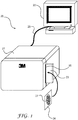
- FIG. 1 is a perspective view of an exemplary biological growth medium processing system 20 capable of implementing one or more of the techniques of this disclosure during the processing of biological growth medium 24.
- System 20 comprises an imaging unit 21 coupled to a computer 22.
- Imaging unit 21 captures images of biological growth medium 24 under two or more different illumination settings (e.g., under different wavelengths of illumination), and computer 22 processes the images to identify and count biological agents on biological growth medium 24.
- illumination settings e.g., under different wavelengths of illumination
- computer 22 processes the images to identify and count biological agents on biological growth medium 24.
- white light and color filters, or other techniques may be used to facilitate illumination at different wavelengths.
- computer 22 and imaging unit 21 are illustrated as separate units, the techniques of this disclosure could also be implemented by a fully integrated system or device in which imaging unit 21 and computer 22 are incorporated into a common device, i.e., a fully integrated biological reader. Furthermore, the techniques of this disclosure could also be used in a modular system that includes one or more imaging units, one or more incubation units, one or more inoculation units, one or more identification element (ID) readers, ID labelers, and/or other devices that operate in a modular processing pipeline associated with biological growth medium 24.
- ID identification element
- imaging unit 21 may include an ID reader to read ID elements (not shown in FIG. 1 ) from biological growth medium 24.
- the ID elements may identify the plate type of biological growth medium 24 and allow computer 22 to select or adjust the image analysis based on the plate type.
- other types of information may also be coded or mapped to ID elements.
- FIG. 2 shows one exemplary biological growth plate that includes an ID element in the form of a bar code. FIG. 2 is discussed in greater detail below.
- computer 22 may include a microprocessor that executes software for image analysis of biological growth medium 24. Accordingly, computer 22 may also include memory to store various types of information, such as image analysis algorithms that execute techniques consistent with the teaching of this disclosure.
- computer 22 may comprise a personal computer (PC), desktop computer, laptop computer, handheld computer, workstation, or the like. Software programs may be loaded on computer 22 to facilitate image analysis of images of biological growth medium 24 generated by imaging unit 21.
- imaging unit 21 is coupled to computer 22 via interface 25.
- Interface 25 may comprise a Universal Serial Bus (USB) interface, a Universal Serial Bus 2 (USB2) interface, an IEEE 1394 FireWire interface, a Small Computer System Interface (SCSI) interface, an Advance Technology Attachment (ATA) interface, a serial ATA interface, a Peripheral Component Interconnect (PCI) interface, a serial or parallel interface, or the like.
- USB Universal Serial Bus
- USB2 Universal Serial Bus 2
- SCSI Small Computer System Interface
- ATA Advance Technology Attachment
- serial ATA interface serial ATA interface
- PCI Peripheral Component Interconnect
- Imaging unit 21 is designed to receive a biological growth medium 24.
- imaging unit 21 includes a housing that defines an input slot 28 for receiving biological growth medium 24.
- a guide mechanism 23 may be formed on the housing to aid insertion of biological growth medium 24 into imaging unit 21.
- Imaging unit 21 also includes an ejection slot (not shown), through which biological growth medium 24 is ejected following imaging of biological growth medium 24.
- Imaging unit 21 may also include other features, such as a display screen (not shown) to display the progress or results of analysis of the biological growth plate to a user. The techniques of this disclosure, however, could be used with a wide variety of other types of imaging devices.
- Imaging unit 21 houses imaging components, such as illumination sources and one or more cameras.
- imaging unit 21 houses a 2-dimensional monochromatic camera for generating one or more monochromatic images of an inserted biological growth medium 24.
- the illumination sources in imaging unit 21 may provide for illumination in two or more different wavelengths of electromagnetic radiation.
- the illumination sources in imaging unit 21 may illuminate the front and/or back sides of biological growth medium 24 during imaging.
- the illuminators can illuminate biological growth medium 24 with two or more different wavelengths of light, and different images of biological growth medium 24 can be generated under the different wavelengths of illumination.
- a transparent platen may be housed within imaging unit 21 to define an imaging location for biological growth medium 24 relative to the camera.
- Imaging unit 21 may communicate the images to computer 22, which may include a processor for performing image analysis.
- Biological growth medium 24 may include a growth area 27 where bacteria or other agents manifest on biological growth medium 24.
- Growth area 27 may comprise a flat surface, a recessed well or any surface useful for biological growth.
- Biological growth medium 24 may be manufactured to included nutrients in growth area 27 to facilitate the rapid growth of a particular biological agent.
- a sample (such as a food sample or laboratory sample) may be added to growth area along with one or more dilution agents, if desired. This process of adding a sample (and possibly a dilution agent) to growth area 27 is referred to as inoculation, and may be performed manually by a user, or automatically by an inoculation unit (not shown in FIG. 1 ). Following inoculation, biological growth medium 24 may then be incubated in an incubation chamber or unit (not shown in FIG. 1 ).
- biological growth medium 24 is processed by imaging unit 21 in order to generate images in the manner described herein.
- imaging unit 21 generates at least two different images under two different wavelengths of illumination light.
- the images are sent from imaging unit 21 to computer 22, which performs image analysis.
- imaging unit 21 may generate first images under an illumination of light in a first range of wavelengths.
- imaging unit 21 may generate second images under illumination of light in a second range of wavelengths.
- biological growth medium 24 is illuminated with two or more different wavelengths of electromagnetic radiation, and images of the biological growth media are captured by imaging unit 21 under these different illuminations.
- the spectral reflectance values in one or more first images can be normalized based on the spectral reflectance values in one or more second images in order to better identify biological agents that manifest on the biological growth media.
- computer 22 uses ratios of the spectral reflectance values in first images to the spectral reflectance values in second images to identify the biological agents relative to a background of biological growth medium 24. In this way, computer 22 uses spectral analysis in the automated detection of biological agents.
- the spectral reflectance values may be given as percentages of reflectance of light at a particular wavelength, and may be associated with specific pixel locations (or specific areas) in the two different images.
- Computer 22 can normalize reflectance values at pixel locations of the first images based on reflectance values at pixel locations in the second images, thereby improving an ability of computer 22 to distinguish the background of biological growth medium 24 from biological agents that manifest on the biological growth medium 24.
- the reflectance values may represent the spectral reflectance of biological growth medium 24 at a given location under the illumination associated with the different images.
- the illumination used by imaging unit 21 for the first images may be within a visible spectrum, and the illumination used by imaging unit 21 for the second images may is between 700 and 1000 nm.
- the spectral response of biological growth medium 24 over a broad range of wavelengths may be exploited to improve automated readout.
- the images may be generated when biological growth medium 24 is in a fixed location to ensure that the pixels of the different images accurately align for purposes of normalization.
- a determination of whether a given sample being tested in biological growth medium 24 is acceptable, in terms of bacterial colony counts or other biological agents may depend on the number of bacterial colonies per unit area. Accordingly, images generated by imaging unit 21 can be analyzed by computer 22 and used to quantify the amount of bacterial colonies per unit area on biological growth medium 24. Moreover, the spectral analysis and normalization techniques described herein can improve the ability of computer 22 to distinguish bacterial colonies or other biological agents from background of biological growth medium 24. The size of individual colonies may also be factored into the analysis, if desired.
- FIG. 2 is a top view of an exemplary biological growth medium in the form of a biological growth plate 50.
- biological growth plate 50 may comprise biological growth plates sold by 3M under the trade name PETRIFILM plates.
- biological growth plate 50 may include an identification element 54 to facilitate automated processing of biological growth plate 50.
- Identification element 54 is illustrated as an optically readable pattern, e.g., a bar code. In other cases, however, identification element 54 may assume a wide variety of optical patterns such as characters, bar codes, two-dimensional bar codes, optical gratings, holograms, phosphorous inks and the like. Moreover, in some embodiments, identification element 54 may comprise visible or non-visible circuits or magnetic elements, which may be readable by magnetic or radio frequency techniques. For example, identification element 54 may comprise any of a wide variety of radio frequency identification (RFID) tags commonly used in many industries for inventory tracking purposes.
- RFID radio frequency identification
- Biological growth plate 50 may facilitate the rapid growth and detection and enumeration of bacteria or other biological agents including, for example, aerobic bacteria, E. coli, coliform, Enterobacteriaceae, yeast, mold, Staphylococcus aureus , Listeria, and campylobacter, and the like.
- aerobic bacteria E. coli, coliform, Enterobacteriaceae, yeast, mold, Staphylococcus aureus , Listeria, and campylobacter, and the like.
- PETRIFILM plates, or other growth media can simplify bacterial testing of food samples.
- biological growth plate 50 defines a growth area 52.
- a determination of whether a given sample being tested in plate 50 is acceptable, in terms of bacterial colony counts, may depend on the number of bacterial colonies per unit area.
- an automated system may process biological growth plate 50 to quantify the amount of bacterial colonies per unit area on plates 50 and may compare the amount, or "count," to a threshold.
- the threshold may represent, for example, a colony count which relates to an acceptable (or unacceptable) number of microorganisms in the original sample.
- the surface of biological growth plate 50 may contain one or more growth enhancing agents designed to facilitate the rapid growth of one or more types of bacteria or other biological agents.
- Biological growth plate 50 may be inoculated with a sample. Inoculation refers to the process of adding a sample of material being tested to the surface of biological growth plate 50 within growth area 52, possibly with a dilution agent. Inoculation may be performed manually or in an automated fashion. After inoculation, biological growth plate 50 can be inserted into an incubation chamber (not shown). In the incubation chamber, microorganisms such as bacteria, yeast, or mold grow on the nutrients in the biological growth plate 50 and, after a period of time, manifest themselves as colonies. The colonies (e.g., mold or other microorganisms), represented by various dots on biological growth plate 50 of FIG.
- area 58 associated with a biological agent may appear different than area 56 associated with a background of biological growth plate 50, particularly in the visible spectrum.
- first images may be generated under illumination by electromagnetic radiation in a first wavelength, e.g., light within the visible spectrum.
- One or more second images may be generated under illumination by electromagnetic radiation in a second wavelength, between 700 and 1000 nm.
- the ratio of spectral reflectance at individual pixel locations in the second image relative to corresponding pixel locations of the first image can aid in detecting area 58 associated with a biological agent relative to area 56 associated with a background.
- Area-based comparisons of area 58 relative to area 56, or possibly pixel-based ratios for every pixel location, can be used to determine whether area 58 (or the pixels within area 58) indeed corresponds to a bacterial colony that has grown on biological growth plate 50.
- a computer may calculate the ratio of reflectance values in the first images relative to the second images in area 58, and the ratio of reflectance values of the first images relative to the second images in area 56. These ratios may provide a more definite distinction between areas 58 and 56 than can be defined from one set of images alone.
- the process of defining theses ratios is referred to as normalization of the first images based on the second images. Such normalization can improve the ability to identify biological agents associated with area 58 relative to background associated with area 56. For example, at every pixel location (or possibly for sets of pixels within different areas), the ratios generated to normalize the first images may be compared to a threshold to determine whether that location corresponds to a biological agent or background. Other more complicated enumeration rules or techniques could also be applied to the calculated ratios at every pixel location (or at different areas defined by sets of pixel locations).
- the reflectance values may be measured in any type of units, and in some cases, may comprise unitless percentage values.
- FIG. 3 is a block diagram of a biological growth medium processing system 30, which may correspond to system 20 of FIG. 1 or another system, such as a fully integrated biological reader or a modular system.
- System 30 includes a computer 32, which may include a processor 33 coupled to memory 36. If desired, computer 32 may be coupled to an output device 38, such as a display screen. Computer 32 may also be coupled to other processing units (not shown) such as inoculation units, incubation units, ID readers, labeling devices, or the like.
- Imaging unit 31 is coupled to computer 32. Imaging unit 31 generates one or more images of a biological growth medium and provides the images to computer 32. Processor 33 processes the images based on image analysis algorithms stored in memory 36. For example, memory 36 may store various processor-executable software instructions that facilitate image analysis of the images generated by imaging unit 31. Processor 33 executes such instructions to carry out the techniques of this disclosure. Output device 38 receives the results determined by processor 33 and provides the results to a user.
- Memory 36 may also store a database 40, as well as database management software for the management of database 40.
- Database 40 of memory 36 can be used to associate the different types of information with different biological growth media.
- database 40 may be used to store spectral profiles associated with different types of biological growth plates. Such spectral profiles, for example, may be used in the processing of biological growth plates, and may possibly aid in distinguishing area 58 ( FIG. 2 ) associated with a biological agent relative to area 56 associated with a background. To generate such spectral profiles, the reflective response of exemplary biological growth media may be recorded via a spectrometer.
- Database 40 may store spectral profiles for a wide variety of different types of biological growth media, and database 40 may be updated from time to time with spectral profiles associated with new types of biological growth media.
- the spectral profiles associated with biological growth plates may aid in determining whether errors or defects exist in the biological media.
- Spectral profiles may be compared to measured data on the biological growth medium in order to identify manufacturer defects or use defects that render the biological growth media inaccurate.
- that medium may be flagged as including possible errors.
- errors for example, may be due to aging, manufacturing defects, or improper use by the lab technician or other user.
- improper or excessive inoculation on a biological growth medium may cause the biological growth medium to be overfilled with inoculants, possibly causing errors that can be detected by comparison of measured reflectance values to expected spectral profiles associated with the biological media.
- Each type of biological growth plate may define a unique spectral signature. If measured reflectance values in one or more areas do not match the expected values, as defined by the unique spectral signature, the medium may be flagged as including possible errors. In this way, biological growth media may be processed based on the spectral profiles in order to improve the integrity of the automated analysis of biological growth media.
- the spectral profiles might be used for other purposes, in addition to checking for clear errors due to aging, manufacturing defects or improper inoculation.
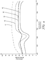
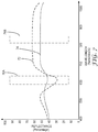
- FIG. 4 is a graph illustrating the spectral response associated with different locations on a biological growth medium.
- the graph of FIG. 4 provides a rough illustration of data gathered in an experiment performed with respect to a PETRIFILM Yeast and Mold Count Plate, hereinafter, referred to as "PETRIFILM YM Plate", commercially available from 3M Company of Saint Paul Minnesota.
- the PETRIFILM YM Plate was inoculated with mold (M6 Strain) and incubated according to the specification of the PETRIFILM YM Plate.
- An Ocean Optics model number USB4000 spectrometer was used to measure reflectivity of the PETRIFILM YM Plate under a Halogen light source.
- Line 41 corresponds to the spectral response associated with a background edge location (i.e., a first background location) on the PETRIFILM YM Plate.
- Line 42 corresponds to the spectral response associated with a biological agent (i.e., a first agent) formed on the PETRIFILM YM Plate.
- Line 43 corresponds to the spectral response associated with a non-edge background location (i.e., a second background location) on the PETRIFILM YM Plate.
- Line 44 corresponds to the spectral response associated with another non-edge background location (i.e., a third background location) on the PETRIFILM YM Plate.
- Line 45 corresponds to the spectral response associated with another biological agent (i.e., a second agent) formed on the PETRIFILM YM Plate.
- the spectral information in the visible spectrum between 400 nanometers to 700 nanometers, and specifically between 500 and 700 nanometers carries substantially all of the information that distinguishes lines 42 and 45 (corresponding to the biological agents) from lines 41, 43 and 44 (corresponding to different background locations). Furthermore, line 42 shows less reflectance than lines 43 and 44 in a substantial portion of the visible spectrum, but shows more reflectance than lines 43 and 44 at wavelengths above 700 nanometers. In wavelengths between 800 and 900 nanometers, all lines are approximately parallel.
- measured spectral reflectance at wavelengths between 700 and 1000 nanometers, or more specifically between 800 and 900 nanometers may be used to normalize the measured spectral reflectance in the visible spectrum between 400 and 700 nanometers.
- Expected or measured spectral characteristics of the biological growth medium in different ranges can be exploited by capturing first images of a biological growth medium under illumination at wavelengths in the visible spectrum (e.g., between approximately 500 and approximately 700 nanometers), and capturing second images of a biological growth medium under illumination at wavelengths outside the visible spectrum (e.g., between approximately 800 and approximately 900 nanometers).
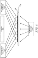
- FIG. 5 is a block diagram illustrating the illumination of a biological growth medium 115 within an illumination device, such as imaging unit 21 of FIG. 1 .
- the illumination device includes illumination sources 110A, 110B and 110C (collectively illumination sources 110).
- the illumination device also includes a camera 112, which may comprise a 2-dimensional monochromatic camera or another type of camera.
- Biological growth medium 115 may be held in an imaging location relative to camera 112.
- Biological growth medium 115 may reside on a transparent platen 114, or could be held in place by guide mechanisms, pincers, or other elements with or without the need for platen 114.
- Illumination sources 110 illuminate biological growth medium 115 with two or more different wavelengths of electromagnetic radiation
- camera 112 captures on or more images of biological growth medium 115 under each of these different illuminations.
- camera 112 may capture first images of biological growth medium 115 under illumination by illumination sources 110 with electromagnetic radiation in a first wavelength, e.g., light within the visible spectrum.
- Camera 112 may capture second images of biological growth medium 115 under illumination by illumination sources 110 with electromagnetic radiation in a second wavelength, e.g., light outside the visible spectrum.
- the first and second images may be captured when biological growth medium 115 is held in a fixed location relative to camera 112 to ensure that pixels of the first images correspond to pixels of the second images. These images can then be communicated from camera 112 to a computer for analysis.
- the computer (not shown in FIG. 4 ) can analyze the images and create ratios for every pixel location to normalize the reflectance values of the first images.
- the ratio of spectral reflectance values in a second image relative to a first image can aid in detecting areas of biological growth medium 115 associated with a biological agents relative to areas of biological growth medium 115 associated with a background.
- Illumination sources 110 may comprise any of a wide variety of devices or configurations. Illumination sources 110 may comprise florescent light sources with filters to define the proper wavelengths of illumination. Alternatively, illumination sources 110 may comprise semiconductor light sources, such as light emitting diodes. The light emitting diodes, for example, may be defined to create the wavelengths of illumination, or filters may be used for this purpose. Many other types of illumination sources could also be used. Although FIG. 5 shows illumination sources 110 positioned on the front side and backside of biological growth medium 115, illumination from only one side of biological growth medium 115 could be used in some cases. Indeed, a wide variety of configurations could be used to achieve two different wavelength ranges of illumination consistent with this disclosure.
- illumination source 110A produces the illumination at the first wavelength and illumination source 110B produces the illumination at the second wavelength.
- Illumination source 110C may provide backlighting in the two different wavelengths.
- each of illumination sources 110 may include elements capable of illuminating at the first and second wavelengths. Any number of different wavelength ranges may be used to define images under several different wavelengths of illumination.
- camera 112 Upon capturing the images, camera 112 sends the images to a computer for image analysis consistent with this disclosure. Again, the first and second images may be captured when biological growth medium 115 is held in a fixed location relative to camera 112 to ensure that pixels of the first images correspond to pixels of the second images.
- white light illumination may be used with optical filters, either stationary or in a filter wheel.
- white light illumination may be used with inserted optical filters on the image sensor in the form of a mask array, e.g., similar to a Bayer mask.
- the reflectance values of pixel locations in a first spectral image can be normalized based on the reflectance values for the same spatial pixel locations in one or more second spectral image.
- the first image may be associated with a different wavelength of illumination than the one or more second images. Additional images at different wavelengths of illumination may also be used.
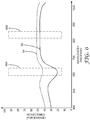
- FIG. 6 is a graph illustrating the spectral response associated with an element formed on a biological growth medium and the spectral response associated with a background area on the biological growth medium.
- line 64 corresponds to line 44 of FIG. 4
- line 65 corresponds to line 45 of FIG. 4 .
- Windows 66A and 66B may define the illumination wavelength ranges used to capture first images and second images respectively. For each of the images, the intensity of each pixel location may be determined, and a ratio of the intensities in windows 66A (associated with a first spectral image) and 66B (associated with a second spectral image) may be determined.
- This process may be viewed as normalizing the reflectance values of the first images associated with window 66A based on second images associated with window 66B. Such normalization by use of ratios can improve the ability to detect whether each given pixel is associated with a background or a biological agent.
- the expected spectral profile associated with backgrounds and agents may be programmed into the computer, and used to augment the analysis by providing expected values or expected ratios for pixels in the background and pixels associated with biological agents. In this way, expected spectral profiles may aid in identifying biological agents. As noted, the expected spectral profiles may also be used for quality control and detection of probably errors due to aging, manufacturing defects or improper inoculation.
- the techniques of this disclosure may significantly improve the ability to differentiate background from biological agents. Even if the absolute differences between reflectance of background and biological agents in images generated under the first illumination are not significant, the normalized differences may be significant. Accordingly, the normalization techniques of this disclosure may yield improvements in the ability to differentiate or distinguish background regions from biological agents that form on the biological growth medium. At every pixel location (or possibly for sets of pixels within different areas), the ratios generated to normalize the first images may be compared to a threshold to determine whether that location corresponds to a biological agent or background. Other more complicated enumeration rules or techniques could also be applied to the calculated ratios at every pixel location (or at different areas defined by sets of pixel locations).
- FIG. 7 is another graph illustrating the spectral response associated with an element formed on a biological growth medium and the spectral response associated with a background area on the biological growth medium.
- line 74 corresponds to line 44 of FIG. 4
- line 72 corresponds to line 42 of FIG. 4 .
- Windows 76A and 76B may define the illumination used to capture first images and second images respectively. For each of the images, the intensity of each pixel location may be determined, and a ratio of the intensities in windows 76A and 76B may be determined. This process may be viewed as normalizing the spectral reflectance values of the first images associated with window 76A based on spectral reflectance values of the second images associated with window 76B. The ratios, then, can be compared to one or more thresholds to determine whether the pixel locations correspond to biological agents or to background.
- this normalization by use of ratios can improve the ability to detect whether each given pixel is associated with a background or a biological agent.
- the expected spectral profile associated with backgrounds and agents may be programmed into the computer, and used to augment the analysis by providing expected values or expected ratios for pixels in the background and pixels associated with biological agents.
- the ability to differentiate background (associated with line 74) from biological agents (associated with line 72) may be improved significantly relative to an absolute comparison of values in one frequency range (e.g., defined by first window 76A).
- first window 76A an absolute comparison of values in one frequency range
- the normalized differences may be over thirty percent.
- the use of normalization techniques or ratios as outlined herein may yield more than 100 percent improvements in quantified differences of pixels associated with a biological agent relative to pixels in the background.
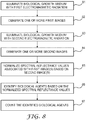
- FIG. 8 is a flow diagram illustrating a technique consistent with this disclosure.
- imaging unit 21 illuminates biological growth medium 24 with first electromagnetic radiation (as shown in step 81), and generates one or more first images of biological growth medium 24 illuminated with the first electromagnetic radiation (as shown in step 82).
- Imaging unit 21 also illuminates biological growth medium 24 with second electromagnetic radiation (as shown in step 83), and generates one or more second images of the biological growth medium illuminated with the second electromagnetic radiation (as shown in step 84).
- the generated images may be sent to computer 22 for image analysis.
- Computer 22 counts biological agents on biological growth medium 24 based on the first and second images.
- computer 22 normalizes spectral reflectance values in the one or more first images based on the one or more second images (as shown in step 85), identifies the biological agents based on the normalized spectral reflectance values (as shown in step 86), and counts the identified biological agents (as shown in step 87).
- computer 22 determines ratios of spectral reflectance values in the one or more first images to spectral reflectance values in the one or more second images, identifies the biological agents based on the ratios, and counts the identified biological agents.
- the first electromagnetic radiation may be within a visible spectrum, and the second electromagnetic radiation may be outside the visible spectrum.
- the first electromagnetic radiation may comprise light having a wavelength between approximately 500 and 700 nanometers
- the second electromagnetic radiation may comprise light having a wavelength between approximately 800 and 900 nanometers.
- computer 22 may store a spectral profile associated with the biological growth medium, in which case the identification of biological agents on biological growth medium 24 may be based on the first and second images and the stored spectral profile.
- the stored spectral profiles may be used to process the biological growth medium, possibly providing a quality check on the biological growth medium.
- Computer 22 may be updated with new spectral profiles, as new types of biological growth plates are developed.
- FIG. 9 is another flow diagram illustrating a technique consistent with this disclosure.
- imaging unit 21 illuminates biological growth medium 24 with electromagnetic radiation outside a visible spectrum (as shown in step 91), and generates one or more images of biological growth medium 24 illuminated with the electromagnetic radiation outside the visible spectrum (as shown in step 92).
- the generated images may be sent to computer 22 for image analysis, and computer 22 may count biological agents on biological growth medium 24 based on the one or more images (as shown in step 93).
- the electromagnetic radiation that is outside the visible spectrum may comprise light having a wavelength between approximately 700 and approximately 1000 nanometers, and more specifically between approximately 800 and approximately 900 nanometers. Images within the visible spectrum may also be generated, in which case, computer 22 may count biological agents on biological growth medium 24 based on one or more first images associated with illumination in the visible spectrum, and one or more second images associate with illumination outside the visible spectrum.
- the techniques described herein may be implemented in hardware, software, firmware, or any combination thereof. If implemented in software, the techniques may be realized at least in part by a computer-readable medium comprising instructions that, when executed by computer of a biological growth medium processing system, cause the computer to perform one or more of the techniques of this disclosure.
- the computer-readable data storage medium may form part of a computer program product, which may include packaging materials.
- the computer-readable medium may comprise random access memory (RAM) such as synchronous dynamic random access memory (SDRAM), read-only memory (ROM), non-volatile random access memory (NVRAM), electrically erasable programmable read-only memory (EEPROM), FLASH memory, magnetic or optical data storage media, and the like.
- RAM random access memory
- SDRAM synchronous dynamic random access memory
- ROM read-only memory
- NVRAM non-volatile random access memory
- EEPROM electrically erasable programmable read-only memory
- FLASH memory magnetic or optical data storage media, and the like.
- the computer-readable instructions may be executed in the computer of the system by one or more processors, general purpose microprocessors, ASICs, FPGAs, or other equivalent integrated or discrete logic circuitry. Accordingly, the term "processor,” as used herein may refer to any structure suitable for implementation of the techniques described herein.
- a computer-readable medium comprising instructions that upon execution in a computer of a biological growth medium processing system cause the computer to receive one or more images of the biological growth medium, the one or more images having been generated during illumination of the biological growth medium with the electromagnetic radiation outside the visible spectrum, and count biological agents on the biological growth medium based on the one or more images.
- this disclosure may provide a computer-readable medium comprising instructions that upon execution in a computer of a biological growth medium processing system cause the computer to receive one or more first images of the biological growth medium, the one or more first images having been generated during illumination of the biological growth medium with first electromagnetic radiation, receive one or more second images of the biological growth medium, the one or more second images having been generated during illumination of the biological growth medium with second electromagnetic radiation, normalize spectral reflectance values in the one or more first images based on the one or more second images, and count the biological agents based on the normalized spectral reflectance values.
- this disclosure may be directed to a circuit, such as an integrated circuit, ASIC, FPGA, logic, or various combinations thereof configured to perform one or more of the techniques described herein.
Claims (3)
- Procédé comprenant :l'éclairage d'une plaque de croissance biologique avec un premier rayonnement électromagnétique qui estau sein du spectre visible ;l'utilisation d'un dispositif d'imagerie pour générer une ou plusieurs premières images de la plaque de croissance biologique éclairée avec le premier rayonnement électromagnétique ;l'éclairage du milieu de croissance biologique avec un deuxième rayonnement électromagnétique ayant une longueur d'onde entre 700 et 1000 nanomètres ;l'utilisation d'un dispositif d'imagerie pour générer une ou plusieurs deuxièmes images de laplaque de croissance biologique éclairée avec le deuxième rayonnement électromagnétique ;la normalisation des valeurs de réflectance spectrale dans la ou les premières images sur la base de la ou des deuxièmes images ;l'identification de colonies de micro-organismes sur la base des valeurs normalisées de réflectance spectrale ; etla numération des colonies de micro-organismes identifiées.
- Procédé selon la revendication 1, comprenant en outre :la détermination de rapports de réflectance spectrale dans la ou les premières images à la réflectance spectrale dans la ou les deuxièmes images ;l'identification des colonies de micro-organismes sur la base des rapports ; etla numération des colonies de micro-organismes identifiées.
- Procédé selon la revendication 1, comprenant en outre :le stockage d'un profil spectral associé à la plaque de croissance biologique ; etle traitement de la plaque de croissance biologique sur la base du profil spectral stocké.
Applications Claiming Priority (2)
| Application Number | Priority Date | Filing Date | Title |
|---|---|---|---|
| US3945308P | 2008-03-26 | 2008-03-26 | |
| EP09724123.6A EP2271911B1 (fr) | 2008-03-26 | 2009-03-17 | Analyse spectrale de milieux de croissance biologique |
Related Parent Applications (2)
| Application Number | Title | Priority Date | Filing Date |
|---|---|---|---|
| EP09724123.6 Division | 2009-03-17 | ||
| EP09724123.6A Division EP2271911B1 (fr) | 2008-03-26 | 2009-03-17 | Analyse spectrale de milieux de croissance biologique |
Publications (3)
| Publication Number | Publication Date |
|---|---|
| EP2653852A2 EP2653852A2 (fr) | 2013-10-23 |
| EP2653852A3 EP2653852A3 (fr) | 2014-03-19 |
| EP2653852B1 true EP2653852B1 (fr) | 2018-04-25 |
Family
ID=41114585
Family Applications (2)
| Application Number | Title | Priority Date | Filing Date |
|---|---|---|---|
| EP13176772.5A Not-in-force EP2653852B1 (fr) | 2008-03-26 | 2009-03-17 | Analyse spectrale de milieux de croissance biologique |
| EP09724123.6A Not-in-force EP2271911B1 (fr) | 2008-03-26 | 2009-03-17 | Analyse spectrale de milieux de croissance biologique |
Family Applications After (1)
| Application Number | Title | Priority Date | Filing Date |
|---|---|---|---|
| EP09724123.6A Not-in-force EP2271911B1 (fr) | 2008-03-26 | 2009-03-17 | Analyse spectrale de milieux de croissance biologique |
Country Status (11)
| Country | Link |
|---|---|
| US (2) | US8417014B2 (fr) |
| EP (2) | EP2653852B1 (fr) |
| JP (1) | JP5608159B2 (fr) |
| KR (1) | KR20110005813A (fr) |
| CN (1) | CN101981430B (fr) |
| BR (1) | BRPI0907064A2 (fr) |
| CA (1) | CA2718314A1 (fr) |
| ES (1) | ES2434964T3 (fr) |
| MX (1) | MX2010010415A (fr) |
| TW (1) | TW200946896A (fr) |
| WO (1) | WO2009120532A2 (fr) |
Families Citing this family (21)
| Publication number | Priority date | Publication date | Assignee | Title |
|---|---|---|---|---|
| US8512975B2 (en) | 2008-07-24 | 2013-08-20 | Biomerieux, Inc. | Method for detection and characterization of a microorganism in a sample using time dependent spectroscopic measurements |
| US10167494B2 (en) | 2008-10-31 | 2019-01-01 | Biomerieux, Inc. | Method for detection, characterization and/or identification of microorganisms in a sealed container |
| AU2009333848B2 (en) | 2008-12-16 | 2016-02-18 | Biomerieux, Inc. | Methods for the characterization of microorganisms on solid or semi-solid media |
| US9025850B2 (en) * | 2010-06-25 | 2015-05-05 | Cireca Theranostics, Llc | Method for analyzing biological specimens by spectral imaging |
| US9129371B2 (en) * | 2010-06-25 | 2015-09-08 | Cireca Theranostics, Llc | Method for analyzing biological specimens by spectral imaging |
| US20140252237A1 (en) * | 2011-10-17 | 2014-09-11 | D.I. R. Technologies (Detection Ir) Ltd. | Methods of detecting the presence of microorganisms in a sample |
| JP5943314B2 (ja) * | 2013-03-22 | 2016-07-05 | 大日本印刷株式会社 | 画像解析システム、培地情報登録システム、プログラム及び衛生管理システム |
| ITMI20130692A1 (it) | 2013-04-26 | 2014-10-27 | Copan Italia Spa | Dispositivo e procedimento per il processamento automatico di piastre di coltura per campioni microbiologici |
| US9212996B2 (en) * | 2013-08-05 | 2015-12-15 | Tellspec, Inc. | Analyzing and correlating spectra, identifying samples and their ingredients, and displaying related personalized information |
| ES2867811T3 (es) | 2014-01-30 | 2021-10-20 | Bd Kiestra Bv | Sistema y método para obtener imágenes de muestras biológicas dispuestas en medios de cultivo |
| US10407654B1 (en) | 2014-03-21 | 2019-09-10 | Charm Sciences, Inc. | Growth plate devices, kits and assemblies |
| JP6845221B2 (ja) | 2015-04-23 | 2021-03-17 | ビーデー キーストラ ビー.ヴィー. | プレート培地上にストリークされた試料からの自動化された微生物コロニーカウントのための方法及びシステム |
| US10521910B2 (en) | 2015-04-23 | 2019-12-31 | Bd Kiestra B.V. | Colony contrast gathering |
| US10460439B1 (en) | 2015-08-12 | 2019-10-29 | Cireca Theranostics, Llc | Methods and systems for identifying cellular subtypes in an image of a biological specimen |
| US10563164B1 (en) | 2015-10-08 | 2020-02-18 | Charm Sciences, Inc. | Plate reader |
| US10988720B1 (en) | 2015-11-09 | 2021-04-27 | Charm Sciences, Inc. | Peel plate assembly |
| US9928403B2 (en) * | 2016-02-09 | 2018-03-27 | Molecular Devices, Llc | System and method for image analysis of multi-dimensional data |
| US10495563B1 (en) | 2016-04-28 | 2019-12-03 | Charm Sciences, Inc. | Plate reader observation methods and operation |
| CN107092907B (zh) * | 2017-05-31 | 2020-01-14 | 赵晓飞 | 面向血液细菌培养的生长曲线处理方法、装置及系统 |
| CN108760649A (zh) * | 2018-05-04 | 2018-11-06 | 中山康天晟合生物技术有限公司 | 一种培养基生产工艺 |
| JP7413775B2 (ja) * | 2019-12-26 | 2024-01-16 | 株式会社島津製作所 | イメージング分析データ処理方法及び装置 |
Citations (1)
| Publication number | Priority date | Publication date | Assignee | Title |
|---|---|---|---|---|
| US20040101951A1 (en) * | 2002-11-27 | 2004-05-27 | Albert Vent | Mounting platform for biological growth plate scanner |
Family Cites Families (18)
| Publication number | Priority date | Publication date | Assignee | Title |
|---|---|---|---|---|
| US102903A (en) * | 1870-05-10 | Improved brick-machine | ||
| US101951A (en) * | 1870-04-12 | Improvement in railway-switches | ||
| US53266A (en) * | 1866-03-20 | Improved apparatus for desulphurizing ores | ||
| US53265A (en) * | 1866-03-20 | Improvement in looms | ||
| US101954A (en) * | 1870-04-12 | Improvement in lubricators | ||
| US185178A (en) * | 1876-12-12 | Improvement in railroad-jacks | ||
| US6063590A (en) * | 1991-11-18 | 2000-05-16 | The United States Of America As Represented By The Administrator Of The U.S. Environmental Protection Agency | Membrane filter agar medium containing two enzyme substrates used for the simultaneous detection of total coliforms and E. coli. |
| DE69314959T2 (de) * | 1992-07-13 | 1998-06-18 | Minnesota Mining & Mfg | Verfahren zum zählen von objekten in einem rasterabgetasteten teilbild. |
| US7057721B2 (en) * | 2002-01-10 | 2006-06-06 | Chemimage Corporation | Wide field method for detecting pathogenic microorganisms |
| US7351574B2 (en) * | 2002-11-27 | 2008-04-01 | 3M Innovative Properties Company | Loading and ejection systems for biological growth plate scanner |
| US7298885B2 (en) * | 2002-11-27 | 2007-11-20 | 3M Innovative Properties Company | Biological growth plate scanner with automated image processing profile selection |
| US20040101954A1 (en) | 2002-11-27 | 2004-05-27 | Graessle Josef A. | Back side plate illumination for biological growth plate scanner |
| US20040102903A1 (en) | 2002-11-27 | 2004-05-27 | Graessle Josef A. | Biological growth plate scanner |
| KR101094590B1 (ko) * | 2002-11-27 | 2011-12-15 | 쓰리엠 이노베이티브 프로퍼티즈 컴파니 | 생물학적 생장판 스캐너용 적재 및 방출 시스템 |
| US7496225B2 (en) * | 2003-09-04 | 2009-02-24 | 3M Innovative Properties Company | Biological growth plate scanner with automated intake |
| US7298886B2 (en) | 2003-09-05 | 2007-11-20 | 3M Innovative Properties Company | Counting biological agents on biological growth plates |
| US8097416B2 (en) * | 2003-09-11 | 2012-01-17 | Ibis Biosciences, Inc. | Methods for identification of sepsis-causing bacteria |
| WO2006078943A2 (fr) * | 2005-01-19 | 2006-07-27 | Micro Beef Technologies, Ltd. | Procede et systeme permettant le suivi et la gestion d'animaux et/ou de produits alimentaires |
-
2009
- 2009-03-17 US US12/921,418 patent/US8417014B2/en not_active Expired - Fee Related
- 2009-03-17 MX MX2010010415A patent/MX2010010415A/es active IP Right Grant
- 2009-03-17 JP JP2011501905A patent/JP5608159B2/ja not_active Expired - Fee Related
- 2009-03-17 EP EP13176772.5A patent/EP2653852B1/fr not_active Not-in-force
- 2009-03-17 KR KR1020107023199A patent/KR20110005813A/ko not_active Application Discontinuation
- 2009-03-17 BR BRPI0907064-8A patent/BRPI0907064A2/pt not_active Application Discontinuation
- 2009-03-17 CN CN2009801107592A patent/CN101981430B/zh not_active Expired - Fee Related
- 2009-03-17 ES ES09724123T patent/ES2434964T3/es active Active
- 2009-03-17 CA CA2718314A patent/CA2718314A1/fr not_active Abandoned
- 2009-03-17 WO PCT/US2009/037359 patent/WO2009120532A2/fr active Application Filing
- 2009-03-17 EP EP09724123.6A patent/EP2271911B1/fr not_active Not-in-force
- 2009-03-25 TW TW098109786A patent/TW200946896A/zh unknown
-
2013
- 2013-03-04 US US13/783,511 patent/US8588505B2/en active Active
Patent Citations (1)
| Publication number | Priority date | Publication date | Assignee | Title |
|---|---|---|---|---|
| US20040101951A1 (en) * | 2002-11-27 | 2004-05-27 | Albert Vent | Mounting platform for biological growth plate scanner |
Also Published As
| Publication number | Publication date |
|---|---|
| CN101981430B (zh) | 2013-03-27 |
| US20110150314A1 (en) | 2011-06-23 |
| WO2009120532A3 (fr) | 2009-12-30 |
| JP5608159B2 (ja) | 2014-10-15 |
| EP2271911B1 (fr) | 2013-08-21 |
| ES2434964T3 (es) | 2013-12-18 |
| WO2009120532A2 (fr) | 2009-10-01 |
| MX2010010415A (es) | 2010-11-04 |
| BRPI0907064A2 (pt) | 2015-07-07 |
| EP2271911A4 (fr) | 2011-08-17 |
| EP2653852A3 (fr) | 2014-03-19 |
| JP2011515104A (ja) | 2011-05-19 |
| US20130177231A1 (en) | 2013-07-11 |
| EP2653852A2 (fr) | 2013-10-23 |
| US8588505B2 (en) | 2013-11-19 |
| KR20110005813A (ko) | 2011-01-19 |
| US8417014B2 (en) | 2013-04-09 |
| CA2718314A1 (fr) | 2009-10-01 |
| CN101981430A (zh) | 2011-02-23 |
| TW200946896A (en) | 2009-11-16 |
| EP2271911A2 (fr) | 2011-01-12 |
Similar Documents
| Publication | Publication Date | Title |
|---|---|---|
| EP2653852B1 (fr) | Analyse spectrale de milieux de croissance biologique | |
| US9809836B2 (en) | Method of differentiating microbial colonies in an image | |
| US9933446B2 (en) | Processing of biological growth media based on measured manufacturing characteristics | |
| EP2323070B1 (fr) | Numeration d'agents biologiques sur des plaques de croissance biologique | |
| US9916491B2 (en) | Method of detecting gas-producing microbial colonies | |
| US8417013B2 (en) | Information management in automated processing of biological growth media | |
| CN109415753B (zh) | 鉴定细菌革兰氏类型的方法和系统 | |
| MX2014010847A (es) | Método y sistema para la detección de crecimiento microbiano en un recipiente de especímenes. | |
| Abeysekera et al. | Digital pathology: Identifying spongiosis in unstained histopathology specimen |
Legal Events
| Date | Code | Title | Description |
|---|---|---|---|
| PUAI | Public reference made under article 153(3) epc to a published international application that has entered the european phase |
Free format text: ORIGINAL CODE: 0009012 |
|
| AC | Divisional application: reference to earlier application |
Ref document number: 2271911 Country of ref document: EP Kind code of ref document: P |
|
| AK | Designated contracting states |
Kind code of ref document: A2 Designated state(s): AT BE BG CH CY CZ DE DK EE ES FI FR GB GR HR HU IE IS IT LI LT LU LV MC MK MT NL NO PL PT RO SE SI SK TR |
|
| PUAL | Search report despatched |
Free format text: ORIGINAL CODE: 0009013 |
|
| AK | Designated contracting states |
Kind code of ref document: A3 Designated state(s): AT BE BG CH CY CZ DE DK EE ES FI FR GB GR HR HU IE IS IT LI LT LU LV MC MK MT NL NO PL PT RO SE SI SK TR |
|
| RIC1 | Information provided on ipc code assigned before grant |
Ipc: C12Q 1/06 20060101ALI20140212BHEP Ipc: G01N 21/01 20060101AFI20140212BHEP Ipc: C12M 1/34 20060101ALI20140212BHEP |
|
| 17P | Request for examination filed |
Effective date: 20140919 |
|
| RBV | Designated contracting states (corrected) |
Designated state(s): AT BE BG CH CY CZ DE DK EE ES FI FR GB GR HR HU IE IS IT LI LT LU LV MC MK MT NL NO PL PT RO SE SI SK TR |
|
| STAA | Information on the status of an ep patent application or granted ep patent |
Free format text: STATUS: EXAMINATION IS IN PROGRESS |
|
| 17Q | First examination report despatched |
Effective date: 20161107 |
|
| GRAP | Despatch of communication of intention to grant a patent |
Free format text: ORIGINAL CODE: EPIDOSNIGR1 |
|
| STAA | Information on the status of an ep patent application or granted ep patent |
Free format text: STATUS: GRANT OF PATENT IS INTENDED |
|
| INTG | Intention to grant announced |
Effective date: 20170927 |
|
| GRAS | Grant fee paid |
Free format text: ORIGINAL CODE: EPIDOSNIGR3 |
|
| GRAA | (expected) grant |
Free format text: ORIGINAL CODE: 0009210 |
|
| STAA | Information on the status of an ep patent application or granted ep patent |
Free format text: STATUS: THE PATENT HAS BEEN GRANTED |
|
| AC | Divisional application: reference to earlier application |
Ref document number: 2271911 Country of ref document: EP Kind code of ref document: P |
|
| AK | Designated contracting states |
Kind code of ref document: B1 Designated state(s): AT BE BG CH CY CZ DE DK EE ES FI FR GB GR HR HU IE IS IT LI LT LU LV MC MK MT NL NO PL PT RO SE SI SK TR |
|
| REG | Reference to a national code |
Ref country code: GB Ref legal event code: FG4D |
|
| REG | Reference to a national code |
Ref country code: CH Ref legal event code: EP |
|
| REG | Reference to a national code |
Ref country code: AT Ref legal event code: REF Ref document number: 993444 Country of ref document: AT Kind code of ref document: T Effective date: 20180515 |
|
| REG | Reference to a national code |
Ref country code: IE Ref legal event code: FG4D |
|
| REG | Reference to a national code |
Ref country code: DE Ref legal event code: R096 Ref document number: 602009052041 Country of ref document: DE |
|
| REG | Reference to a national code |
Ref country code: NL Ref legal event code: MP Effective date: 20180425 |
|
| REG | Reference to a national code |
Ref country code: LT Ref legal event code: MG4D |
|
| PG25 | Lapsed in a contracting state [announced via postgrant information from national office to epo] |
Ref country code: NL Free format text: LAPSE BECAUSE OF FAILURE TO SUBMIT A TRANSLATION OF THE DESCRIPTION OR TO PAY THE FEE WITHIN THE PRESCRIBED TIME-LIMIT Effective date: 20180425 |
|
| PG25 | Lapsed in a contracting state [announced via postgrant information from national office to epo] |
Ref country code: LT Free format text: LAPSE BECAUSE OF FAILURE TO SUBMIT A TRANSLATION OF THE DESCRIPTION OR TO PAY THE FEE WITHIN THE PRESCRIBED TIME-LIMIT Effective date: 20180425 Ref country code: PL Free format text: LAPSE BECAUSE OF FAILURE TO SUBMIT A TRANSLATION OF THE DESCRIPTION OR TO PAY THE FEE WITHIN THE PRESCRIBED TIME-LIMIT Effective date: 20180425 Ref country code: ES Free format text: LAPSE BECAUSE OF FAILURE TO SUBMIT A TRANSLATION OF THE DESCRIPTION OR TO PAY THE FEE WITHIN THE PRESCRIBED TIME-LIMIT Effective date: 20180425 Ref country code: BG Free format text: LAPSE BECAUSE OF FAILURE TO SUBMIT A TRANSLATION OF THE DESCRIPTION OR TO PAY THE FEE WITHIN THE PRESCRIBED TIME-LIMIT Effective date: 20180725 Ref country code: FI Free format text: LAPSE BECAUSE OF FAILURE TO SUBMIT A TRANSLATION OF THE DESCRIPTION OR TO PAY THE FEE WITHIN THE PRESCRIBED TIME-LIMIT Effective date: 20180425 Ref country code: NO Free format text: LAPSE BECAUSE OF FAILURE TO SUBMIT A TRANSLATION OF THE DESCRIPTION OR TO PAY THE FEE WITHIN THE PRESCRIBED TIME-LIMIT Effective date: 20180725 Ref country code: SE Free format text: LAPSE BECAUSE OF FAILURE TO SUBMIT A TRANSLATION OF THE DESCRIPTION OR TO PAY THE FEE WITHIN THE PRESCRIBED TIME-LIMIT Effective date: 20180425 |
|
| PG25 | Lapsed in a contracting state [announced via postgrant information from national office to epo] |
Ref country code: LV Free format text: LAPSE BECAUSE OF FAILURE TO SUBMIT A TRANSLATION OF THE DESCRIPTION OR TO PAY THE FEE WITHIN THE PRESCRIBED TIME-LIMIT Effective date: 20180425 Ref country code: GR Free format text: LAPSE BECAUSE OF FAILURE TO SUBMIT A TRANSLATION OF THE DESCRIPTION OR TO PAY THE FEE WITHIN THE PRESCRIBED TIME-LIMIT Effective date: 20180726 Ref country code: HR Free format text: LAPSE BECAUSE OF FAILURE TO SUBMIT A TRANSLATION OF THE DESCRIPTION OR TO PAY THE FEE WITHIN THE PRESCRIBED TIME-LIMIT Effective date: 20180425 |
|
| REG | Reference to a national code |
Ref country code: AT Ref legal event code: MK05 Ref document number: 993444 Country of ref document: AT Kind code of ref document: T Effective date: 20180425 |
|
| PG25 | Lapsed in a contracting state [announced via postgrant information from national office to epo] |
Ref country code: PT Free format text: LAPSE BECAUSE OF FAILURE TO SUBMIT A TRANSLATION OF THE DESCRIPTION OR TO PAY THE FEE WITHIN THE PRESCRIBED TIME-LIMIT Effective date: 20180827 |
|
| REG | Reference to a national code |
Ref country code: DE Ref legal event code: R097 Ref document number: 602009052041 Country of ref document: DE |
|
| PG25 | Lapsed in a contracting state [announced via postgrant information from national office to epo] |
Ref country code: SK Free format text: LAPSE BECAUSE OF FAILURE TO SUBMIT A TRANSLATION OF THE DESCRIPTION OR TO PAY THE FEE WITHIN THE PRESCRIBED TIME-LIMIT Effective date: 20180425 Ref country code: RO Free format text: LAPSE BECAUSE OF FAILURE TO SUBMIT A TRANSLATION OF THE DESCRIPTION OR TO PAY THE FEE WITHIN THE PRESCRIBED TIME-LIMIT Effective date: 20180425 Ref country code: CZ Free format text: LAPSE BECAUSE OF FAILURE TO SUBMIT A TRANSLATION OF THE DESCRIPTION OR TO PAY THE FEE WITHIN THE PRESCRIBED TIME-LIMIT Effective date: 20180425 Ref country code: EE Free format text: LAPSE BECAUSE OF FAILURE TO SUBMIT A TRANSLATION OF THE DESCRIPTION OR TO PAY THE FEE WITHIN THE PRESCRIBED TIME-LIMIT Effective date: 20180425 Ref country code: DK Free format text: LAPSE BECAUSE OF FAILURE TO SUBMIT A TRANSLATION OF THE DESCRIPTION OR TO PAY THE FEE WITHIN THE PRESCRIBED TIME-LIMIT Effective date: 20180425 Ref country code: AT Free format text: LAPSE BECAUSE OF FAILURE TO SUBMIT A TRANSLATION OF THE DESCRIPTION OR TO PAY THE FEE WITHIN THE PRESCRIBED TIME-LIMIT Effective date: 20180425 |
|
| PG25 | Lapsed in a contracting state [announced via postgrant information from national office to epo] |
Ref country code: IT Free format text: LAPSE BECAUSE OF FAILURE TO SUBMIT A TRANSLATION OF THE DESCRIPTION OR TO PAY THE FEE WITHIN THE PRESCRIBED TIME-LIMIT Effective date: 20180425 |
|
| PLBE | No opposition filed within time limit |
Free format text: ORIGINAL CODE: 0009261 |
|
| STAA | Information on the status of an ep patent application or granted ep patent |
Free format text: STATUS: NO OPPOSITION FILED WITHIN TIME LIMIT |
|
| 26N | No opposition filed |
Effective date: 20190128 |
|
| PG25 | Lapsed in a contracting state [announced via postgrant information from national office to epo] |
Ref country code: SI Free format text: LAPSE BECAUSE OF FAILURE TO SUBMIT A TRANSLATION OF THE DESCRIPTION OR TO PAY THE FEE WITHIN THE PRESCRIBED TIME-LIMIT Effective date: 20180425 |
|
| REG | Reference to a national code |
Ref country code: DE Ref legal event code: R119 Ref document number: 602009052041 Country of ref document: DE |
|
| PG25 | Lapsed in a contracting state [announced via postgrant information from national office to epo] |
Ref country code: MC Free format text: LAPSE BECAUSE OF FAILURE TO SUBMIT A TRANSLATION OF THE DESCRIPTION OR TO PAY THE FEE WITHIN THE PRESCRIBED TIME-LIMIT Effective date: 20180425 |
|
| REG | Reference to a national code |
Ref country code: CH Ref legal event code: PL |
|
| GBPC | Gb: european patent ceased through non-payment of renewal fee |
Effective date: 20190317 |
|
| PG25 | Lapsed in a contracting state [announced via postgrant information from national office to epo] |
Ref country code: LU Free format text: LAPSE BECAUSE OF NON-PAYMENT OF DUE FEES Effective date: 20190317 |
|
| REG | Reference to a national code |
Ref country code: BE Ref legal event code: MM Effective date: 20190331 |
|
| PG25 | Lapsed in a contracting state [announced via postgrant information from national office to epo] |
Ref country code: LI Free format text: LAPSE BECAUSE OF NON-PAYMENT OF DUE FEES Effective date: 20190331 Ref country code: IE Free format text: LAPSE BECAUSE OF NON-PAYMENT OF DUE FEES Effective date: 20190317 Ref country code: GB Free format text: LAPSE BECAUSE OF NON-PAYMENT OF DUE FEES Effective date: 20190317 Ref country code: DE Free format text: LAPSE BECAUSE OF NON-PAYMENT OF DUE FEES Effective date: 20191001 Ref country code: CH Free format text: LAPSE BECAUSE OF NON-PAYMENT OF DUE FEES Effective date: 20190331 |
|
| PG25 | Lapsed in a contracting state [announced via postgrant information from national office to epo] |
Ref country code: BE Free format text: LAPSE BECAUSE OF NON-PAYMENT OF DUE FEES Effective date: 20190331 |
|
| PG25 | Lapsed in a contracting state [announced via postgrant information from national office to epo] |
Ref country code: TR Free format text: LAPSE BECAUSE OF FAILURE TO SUBMIT A TRANSLATION OF THE DESCRIPTION OR TO PAY THE FEE WITHIN THE PRESCRIBED TIME-LIMIT Effective date: 20180425 |
|
| PG25 | Lapsed in a contracting state [announced via postgrant information from national office to epo] |
Ref country code: MT Free format text: LAPSE BECAUSE OF NON-PAYMENT OF DUE FEES Effective date: 20190317 |
|
| PGFP | Annual fee paid to national office [announced via postgrant information from national office to epo] |
Ref country code: FR Payment date: 20210210 Year of fee payment: 13 |
|
| PG25 | Lapsed in a contracting state [announced via postgrant information from national office to epo] |
Ref country code: CY Free format text: LAPSE BECAUSE OF FAILURE TO SUBMIT A TRANSLATION OF THE DESCRIPTION OR TO PAY THE FEE WITHIN THE PRESCRIBED TIME-LIMIT Effective date: 20180425 |
|
| PG25 | Lapsed in a contracting state [announced via postgrant information from national office to epo] |
Ref country code: IS Free format text: LAPSE BECAUSE OF FAILURE TO SUBMIT A TRANSLATION OF THE DESCRIPTION OR TO PAY THE FEE WITHIN THE PRESCRIBED TIME-LIMIT Effective date: 20180825 |
|
| PG25 | Lapsed in a contracting state [announced via postgrant information from national office to epo] |
Ref country code: HU Free format text: LAPSE BECAUSE OF FAILURE TO SUBMIT A TRANSLATION OF THE DESCRIPTION OR TO PAY THE FEE WITHIN THE PRESCRIBED TIME-LIMIT; INVALID AB INITIO Effective date: 20090317 |
|
| PG25 | Lapsed in a contracting state [announced via postgrant information from national office to epo] |
Ref country code: MK Free format text: LAPSE BECAUSE OF FAILURE TO SUBMIT A TRANSLATION OF THE DESCRIPTION OR TO PAY THE FEE WITHIN THE PRESCRIBED TIME-LIMIT Effective date: 20180425 |
|
| PG25 | Lapsed in a contracting state [announced via postgrant information from national office to epo] |
Ref country code: FR Free format text: LAPSE BECAUSE OF NON-PAYMENT OF DUE FEES Effective date: 20220331 |