EP2653794B2 - Rohrverbinder - Google Patents
Rohrverbinder Download PDFInfo
- Publication number
- EP2653794B2 EP2653794B2 EP13163342.2A EP13163342A EP2653794B2 EP 2653794 B2 EP2653794 B2 EP 2653794B2 EP 13163342 A EP13163342 A EP 13163342A EP 2653794 B2 EP2653794 B2 EP 2653794B2
- Authority
- EP
- European Patent Office
- Prior art keywords
- pipeline
- pipe
- pipe connector
- section
- housing part
- Prior art date
- Legal status (The legal status is an assumption and is not a legal conclusion. Google has not performed a legal analysis and makes no representation as to the accuracy of the status listed.)
- Active
Links
Images


Classifications
-
- F—MECHANICAL ENGINEERING; LIGHTING; HEATING; WEAPONS; BLASTING
- F24—HEATING; RANGES; VENTILATING
- F24D—DOMESTIC- OR SPACE-HEATING SYSTEMS, e.g. CENTRAL HEATING SYSTEMS; DOMESTIC HOT-WATER SUPPLY SYSTEMS; ELEMENTS OR COMPONENTS THEREFOR
- F24D19/00—Details
- F24D19/0097—Casings or frame structures for hydraulic components
-
- F—MECHANICAL ENGINEERING; LIGHTING; HEATING; WEAPONS; BLASTING
- F16—ENGINEERING ELEMENTS AND UNITS; GENERAL MEASURES FOR PRODUCING AND MAINTAINING EFFECTIVE FUNCTIONING OF MACHINES OR INSTALLATIONS; THERMAL INSULATION IN GENERAL
- F16L—PIPES; JOINTS OR FITTINGS FOR PIPES; SUPPORTS FOR PIPES, CABLES OR PROTECTIVE TUBING; MEANS FOR THERMAL INSULATION IN GENERAL
- F16L41/00—Branching pipes; Joining pipes to walls
- F16L41/02—Branch units, e.g. made in one piece, welded, riveted
- F16L41/03—Branch units, e.g. made in one piece, welded, riveted comprising junction pieces for four or more pipe members
-
- F—MECHANICAL ENGINEERING; LIGHTING; HEATING; WEAPONS; BLASTING
- F16—ENGINEERING ELEMENTS AND UNITS; GENERAL MEASURES FOR PRODUCING AND MAINTAINING EFFECTIVE FUNCTIONING OF MACHINES OR INSTALLATIONS; THERMAL INSULATION IN GENERAL
- F16L—PIPES; JOINTS OR FITTINGS FOR PIPES; SUPPORTS FOR PIPES, CABLES OR PROTECTIVE TUBING; MEANS FOR THERMAL INSULATION IN GENERAL
- F16L43/00—Bends; Siphons
- F16L43/008—Bends; Siphons made from plastic material
-
- F—MECHANICAL ENGINEERING; LIGHTING; HEATING; WEAPONS; BLASTING
- F16—ENGINEERING ELEMENTS AND UNITS; GENERAL MEASURES FOR PRODUCING AND MAINTAINING EFFECTIVE FUNCTIONING OF MACHINES OR INSTALLATIONS; THERMAL INSULATION IN GENERAL
- F16L—PIPES; JOINTS OR FITTINGS FOR PIPES; SUPPORTS FOR PIPES, CABLES OR PROTECTIVE TUBING; MEANS FOR THERMAL INSULATION IN GENERAL
- F16L47/00—Connecting arrangements or other fittings specially adapted to be made of plastics or to be used with pipes made of plastics
- F16L47/26—Connecting arrangements or other fittings specially adapted to be made of plastics or to be used with pipes made of plastics for branching pipes; for joining pipes to walls; Adaptors therefor
- F16L47/32—Branch units, e.g. made in one piece, welded, riveted
-
- F—MECHANICAL ENGINEERING; LIGHTING; HEATING; WEAPONS; BLASTING
- F16—ENGINEERING ELEMENTS AND UNITS; GENERAL MEASURES FOR PRODUCING AND MAINTAINING EFFECTIVE FUNCTIONING OF MACHINES OR INSTALLATIONS; THERMAL INSULATION IN GENERAL
- F16L—PIPES; JOINTS OR FITTINGS FOR PIPES; SUPPORTS FOR PIPES, CABLES OR PROTECTIVE TUBING; MEANS FOR THERMAL INSULATION IN GENERAL
- F16L9/00—Rigid pipes
- F16L9/22—Pipes composed of a plurality of segments
-
- F—MECHANICAL ENGINEERING; LIGHTING; HEATING; WEAPONS; BLASTING
- F24—HEATING; RANGES; VENTILATING
- F24D—DOMESTIC- OR SPACE-HEATING SYSTEMS, e.g. CENTRAL HEATING SYSTEMS; DOMESTIC HOT-WATER SUPPLY SYSTEMS; ELEMENTS OR COMPONENTS THEREFOR
- F24D19/00—Details
- F24D19/0002—Means for connecting central heating radiators to circulation pipes
Definitions
- the present invention relates to a pipe connector for a domestic installation having a housing and having at least one fluid-flowable pipe, wherein the housing consists of plastic and wherein at the ends of the at least one pipe connections for connection to further pipes are provided, wherein the housing at least two housing parts, wherein the first housing part has a lower pipeline section of the at least one pipeline, wherein the second housing part has an upper pipeline section of the at least one pipeline, wherein the lower pipeline section and / or the upper pipeline section of the at least one pipeline has at least one corner region, wherein a rounding is provided in the at least one corner region, wherein at least one further pipeline is provided, and wherein the first pipeline, the at least one further pipeline in an intersection region crosses. Furthermore, the invention relates to the use of a pipe connector in a drinking water, heating or cooling system.
- Pipe connection systems for domestic installation, in particular for heating systems, are usually made of gunmetal.
- gunmetal In addition to pipe connectors that connect two lines with each other, systems with four terminals are known, which are used for example as a connector of intersecting pipes.
- gunmetal is expensive to manufacture and also has the disadvantage that the production of a component, which is usually done by casting, due to the high copper content of gunmetal is very complex.
- the DE 2 412 303 relates to a piping manifold body for heating systems, which can be used optionally for single-pipe or twin-pipe central heating systems.
- An insert which can be installed in the manifold, separates two pipes in the area where they intersect.
- this manifold has the disadvantage that on the one hand it is very expensive to manufacture.
- a pipe constriction occurs in the crossing area, which causes a significant loss of flow.
- Pipe connectors made of plastic produced by casting are cast in one piece in the prior art by means of injection molding. In order to realize pipelines that can not be demoulded in a direction perpendicular to the mold, slides are used during the casting, which are removed from the mold in the direction of the longitudinal axis of the pipeline.
- the EP 2 420 629 A1 discloses a plastic housing consisting of two shell-shaped parts, which are produced by die-casting and which enclose a drinking water-conducting functional unit. In this case, the housing itself does not come into contact with the fluid flowing through the functional unit.
- WO 2011/066612 A1 discloses a system of fluid conduit components in an air conditioning system.
- the components may have plastic housing and connectable housing halves.
- the present invention has the object to provide a flow-optimized pipe connector made of plastic.
- the first housing part in the crossing region has a pipe segment of the first pipe and that the at least one further pipe in the crossing region has a ramp which is adapted to a fluid which flows through the at least one further pipe via the pipe segment to conduct the first pipeline.
- each pipeline section forms part of the cross section of the pipeline.
- a pipeline section is formed as a shell, which forms 50% of the cross section of the pipeline.
- the at least one pipe of the pipe connector may be formed, for example, as a straight connection or as a pipe bend or T-piece.
- a pipeline can be made by injection molding of a plastic housing consisting of two housing parts and that by the production of the pipe connector in at least two housing parts, which are joined together in a second step, a complex structure of the pipe connector can be realized.
- An injection-molded plastic housing is simple and inexpensive to manufacture. In addition, in contrast to housings, which are produced in a part by injection molding, no problems in demolding particular of parts having a complex structure, from the mold on.
- the lower pipeline section of the at least one pipeline can have at least one corner region, wherein a fillet is provided in the at least one corner region. This rounding off can reduce the formation of laminar flow vortices in the at least one pipeline and thus further optimize the flow behavior of the fluid within this pipeline.
- the upper pipe section of the at least one pipe may have at least one corner region, wherein in the at least one corner region, a fillet is provided.
- the at least two housing parts of the housing according to the invention are permanently joined together by gluing or welding.
- ultrasonic welding, vibration welding, heating element welding, laser welding or infrared welding are methods that are suitable for these purposes. Any other common joining method for plastic parts can also be used for this purpose.
- the lower pipe section of the first housing part and the upper pipe section of the second housing part together form the at least one pipeline.
- the pipe connector according to the invention can be installed to save space in a piping system in which the pipes are close together.
- heater body connections and floor heating pipes often have a small distance between the individual pipes.
- the lower and / or the upper pipeline section of the at least one further pipeline have at least one corner region, wherein a fillet is provided in the at least one corner region.
- the at least one further pipeline can be designed, for example, as a pipe bend or as a T-piece.
- the flow resistance of the fluid flowing through the at least one further pipeline can also be reduced further.
- the first pipe crosses the at least one further pipe in an intersection region.
- the first housing part in the crossing region on a pipe segment of the first pipe.
- the second housing part in the crossing region on a recess. In the connected state of the two housing parts thereby a cavity is formed above the pipe segment, so that it can be ensured that the fluid can flow around the pipe segment of the first pipe on one side.
- the at least one further pipeline has a ramp in the crossing area, which is suitable for directing a fluid which flows through the at least one further pipeline via the pipeline segment of the first pipeline.
- the ramp sets as little resistance to the flowing fluid, so that the flow behavior within the crossing region can be further optimized.
- a rounding is provided in at least one area of the edges of the ramp.
- the formation of laminar flow vortices at the edges can be further reduced by the rounding off.
- the rounding of at least one edge also contributes to the reduction of the flow resistance.
- the angle in the crossing region between the first pipeline and the at least one further pipeline is between 45 ° and 135 °.
- the angle is 90 °.
- the pipe connector can be easily installed in a pipe system.
- the crossing region may be designed so that no or only slight cross-sectional changes occur in both pipelines. If a cross-sectional change does occur, the change in cross section of the first pipeline in the crossing region is preferably less than 20%, in particular less than 10%. This ensures that the flow behavior of the fluid is not influenced too much, for example by a narrowing of the flow cross-section. Thus, the fluid can flow evenly through the first pipeline.
- the change in cross section of the at least one further pipeline in the crossing region may be less than 20%, in particular less than 10%.
- the pipe connector according to the invention can be particularly easily installed in piping systems in the floor or in the wall, in particular at locations where lines intersect.
- the at least one further pipeline has, in a next embodiment, at least two connections for the connection of the pipe connector with at least two further pipes.
- These connections can be designed as a compression connector or as a threaded connection.
- any other type of connection of two pipes, such as flanges or sleeves, may be provided for connection to other pipelines.
- a pipe connector according to any of the embodiments described above is preferably used in a drinking water, heating or cooling system.
- Fig. 1 shows a pipe connector with a housing 2 and with a fluid-flowable pipe 4.
- the housing 2 has a first housing part 18 and a second housing part 20, wherein the two housing parts 18 and 20 are joined together by gluing or welding.
- the pipe 4, which is formed from the two housing parts 18 and 20, is formed as a straight pipe 12.
- connections 6 and 8 of the compound of the pipe 4 with other pipes which are not shown here.
- These connections can be formed, for example, as a compression connector or as a threaded connection.
- any other type of connection of two pipes, such as flanges or sleeves, may be provided for connection to other pipelines.
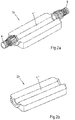
- Fig. 2a shows a first housing part 18 of a pipe connector.
- the first housing part 18 has a lower pipe section 4 ', wherein at the ends of the lower pipe section 4' terminals 6 and 8 are provided for connection to other pipes, which are not shown here.
- the lower pipe section 4 ' is formed as a straight pipe section.
- Fig. 2b shows a second housing part 20 of a pipe connector.
- the second housing part 20 has an upper pipe section 4 ", and this upper pipe section 4" is also formed as a straight pipe section.
- Fig. 3 shows a first housing part 18 of a pipe connector with a lower pipe section 14 'of a first pipe 14.
- the pipe 14 is formed in this embodiment as a pipe bend.
- the first housing part 18 has a lower pipe section 14 'of the pipe bend 14 and connections 6 and 8 for the connection of the pipe bend 14 with further pipes.
- a fillet 24 is provided, which optimizes the flow behavior of the fluid flowing through the pipe bend 14.
- a second housing part which is not shown here, has a corresponding upper pipe section (correspondingly denoted by 14 ") of the pipe bend, so that the pipe bend 14 is formed by the joining of the two housing parts.
- Fig. 4 shows a first housing part 18 of a pipe connector, wherein the pipe 16 is formed as a T-piece.
- the first housing part 18 has a lower pipe section 16 'and connections 6, 8 and 10 for connection to further pipelines.
- Fillets 24 are provided in corner regions 22 of the lower pipe section 16 ', which reduce the occurrence of disturbances of the laminar flow of the fluid flowing through the pipe 16 and thus optimize the flow behavior within the pipe 16.
- the second housing part has an upper pipe section (here corresponding to 16 "), which is designed to be a T-piece in accordance with the previously described lower pipe section 16 '.
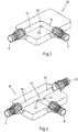
- a first housing part 18 of a first embodiment shows Fig. 5a ,
- a further pipe 28 is provided, wherein both pipes 4 and 28 are formed as straight pipes, which intersect in an intersection region 36.
- the first housing part 18 has a lower pipe section 12 'of the first pipe 12 and a lower pipe section 28' of the second pipe 28.
- the angle a between the lower pipe section 12 'and the lower pipe section 28' is 90 °.
- the first housing part 18 has a pipeline segment 5 of the first pipeline 4.
- a ramp 38 is provided in the crossing region 36, which has a one-sided flow around the pipe segment 5 of the first pipe 4.
- a ramp 38 is provided in the crossing region 36, which allows a one-sided flow around the pipe segment 5 of the first pipe 4.
- fillets 24 are provided in the region of the edges 40 of the ramp 38.
- Fig. 5b shows a second housing part 20 of the embodiment described above.
- the second housing part 20 has an upper pipe section 4 "of the first pipe 4 and an upper pipe section 28" of the second pipe 28, the upper pipe section 4 "of the first pipe 4 crossing the upper pipe section 28" of the second pipe 28 in an intersection area 36 , In the crossing region 36, the second housing part 20 has a recess 42.
- the housing parts 18, 20 form the Fig. 5a and 5b the pipes 4 and 28.
- the recess 42 in the crossing region 36 of the second housing part 20 can be ensured that the fluid flowing through the second pipe 28, the pipe segment 5 of the first pipe 4 can flow around, the flow cross-section is maintained or only slightly by 20%, preferably to 10%, can be reduced.
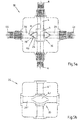
- Fig. 6a and b show a first housing part 18 and a second housing part 20 of a second embodiment of a pipe connector according to the invention, which put together a in Fig. 7 illustrated Form housing 2.
- two pipes 16 and 45 are provided, which are both formed as a tee.
- Fig. 6a shows the first housing part 18 with lower pipe sections 16 'and 45' of the pipes 16 and 45.
- fillets 24 are provided which minimize the flow resistance for the fluid flowing through the pipes 16 and 45.
- the lower pipe section 16 crosseses the lower pipe section 45'. The angle between the intersecting pipe sections is 90 °.
- the first housing part 18 has a pipeline segment 5 of the first pipeline 16. So that the fluid flowing through the second pipeline 45 can optimally flow around the pipeline segment 5 of the first pipeline 16 in the intersection region 36, a ramp 38 is provided which guides the fluid via the pipeline segment 5. In order to minimize the flow resistance, fillets 24 are provided in the region of the edges 40 of the ramp 38. At the ends of the lower pipe sections 16 'and 45', the first housing part 18 has connections 6, 8, 10, 44, 46 and 48 for connection to further pipelines.
- Fig. 6b shows a second housing part 20 of the second embodiment of the pipe connector according to the invention.
- the second housing part 20 has an upper pipe section 16 "of the first pipe 16 and an upper pipe section 45" of the second pipe 45, the upper pipe section 16 "crossing the upper pipe section 45" in an intersection area 36.
- corner regions 22 of the upper pipe sections 16 "and 45" fillets 24 are provided which further optimize the flow behavior of the fluid flowing through the pipe 16 and 45.
- the second housing part 20 has a recess 42.
- the two housing parts 18 and 20 form the Fig. 6a and 6b the pipes 16 and 45.
- Fig. 7 shows the housing 2 of the second embodiment, wherein the two housing parts 18, 20 of the Fig. 6a and 6b are joined together.
- the pipe connector shown has at the ends of the pipes 16 and 45 ports 6, 8, 10, 44, 46 and 48 for connection to other pipes, which are not shown here, on.
- This embodiment of a pipe connector according to the invention can be particularly well integrated into the laying of pipes in the floor or in the wall due to its low height.
Landscapes
- Engineering & Computer Science (AREA)
- General Engineering & Computer Science (AREA)
- Mechanical Engineering (AREA)
- Physics & Mathematics (AREA)
- Thermal Sciences (AREA)
- Chemical & Material Sciences (AREA)
- Combustion & Propulsion (AREA)
- Branch Pipes, Bends, And The Like (AREA)
- Quick-Acting Or Multi-Walled Pipe Joints (AREA)
Priority Applications (2)
| Application Number | Priority Date | Filing Date | Title |
|---|---|---|---|
| PL13163342T PL2653794T5 (pl) | 2012-04-16 | 2013-04-11 | Łącznik do rur |
| HRP20161072T HRP20161072T4 (hr) | 2012-04-16 | 2016-08-24 | Cijevni spojnik |
Applications Claiming Priority (1)
| Application Number | Priority Date | Filing Date | Title |
|---|---|---|---|
| DE102012103260.2A DE102012103260B4 (de) | 2012-04-16 | 2012-04-16 | Rohrverbinder |
Publications (4)
| Publication Number | Publication Date |
|---|---|
| EP2653794A2 EP2653794A2 (de) | 2013-10-23 |
| EP2653794A3 EP2653794A3 (de) | 2015-05-13 |
| EP2653794B1 EP2653794B1 (de) | 2016-06-29 |
| EP2653794B2 true EP2653794B2 (de) | 2019-06-26 |
Family
ID=48095658
Family Applications (1)
| Application Number | Title | Priority Date | Filing Date |
|---|---|---|---|
| EP13163342.2A Active EP2653794B2 (de) | 2012-04-16 | 2013-04-11 | Rohrverbinder |
Country Status (5)
| Country | Link |
|---|---|
| EP (1) | EP2653794B2 (pl) |
| DE (1) | DE102012103260B4 (pl) |
| DK (1) | DK2653794T4 (pl) |
| HR (1) | HRP20161072T4 (pl) |
| PL (1) | PL2653794T5 (pl) |
Families Citing this family (1)
| Publication number | Priority date | Publication date | Assignee | Title |
|---|---|---|---|---|
| TWI829260B (zh) | 2021-07-28 | 2024-01-11 | 美商艾克爾系統公司 | 模組化配件組件以及包含該組件的系統 |
Family Cites Families (7)
| Publication number | Priority date | Publication date | Assignee | Title |
|---|---|---|---|---|
| US3633943A (en) | 1970-02-13 | 1972-01-11 | Johns Manville | Fitting and method of making the same |
| DE2107387A1 (de) | 1970-02-23 | 1971-11-18 | Svenska Flaektfabriken Ab | Verfahren und Anordnung zur Verbindung von Bauteilen bei Ventilationsanlagen mit grossen Anforderungen auf Dichtheit |
| CH678221A5 (pl) | 1987-11-11 | 1991-08-15 | Fischer Ag Georg | |
| US6543404B2 (en) | 2001-04-04 | 2003-04-08 | Dow Global Technologies, Inc. | Adhesively bonded engine intake manifold assembly |
| JP2003148749A (ja) * | 2001-11-12 | 2003-05-21 | Tamai Kankyo Syst Kk | 分岐管箱 |
| AU2010327312B2 (en) | 2009-12-01 | 2016-05-26 | Air Diffusion Agencies Pty Ltd | Ducted heating, ventilation, and air conditioning (HVAC) component and system improvements |
| EP2420629B1 (de) * | 2010-07-28 | 2015-11-04 | Grohe AG | Sanitärarmatur |
-
2012
- 2012-04-16 DE DE102012103260.2A patent/DE102012103260B4/de active Active
-
2013
- 2013-04-11 PL PL13163342T patent/PL2653794T5/pl unknown
- 2013-04-11 DK DK13163342.2T patent/DK2653794T4/da active
- 2013-04-11 EP EP13163342.2A patent/EP2653794B2/de active Active
-
2016
- 2016-08-24 HR HRP20161072T patent/HRP20161072T4/hr unknown
Also Published As
| Publication number | Publication date |
|---|---|
| DE102012103260A1 (de) | 2013-10-17 |
| DK2653794T3 (da) | 2016-08-29 |
| HRP20161072T4 (hr) | 2019-11-15 |
| EP2653794A3 (de) | 2015-05-13 |
| EP2653794A2 (de) | 2013-10-23 |
| PL2653794T5 (pl) | 2019-12-31 |
| DK2653794T4 (da) | 2019-09-23 |
| PL2653794T3 (pl) | 2016-11-30 |
| DE102012103260B4 (de) | 2017-05-18 |
| EP2653794B1 (de) | 2016-06-29 |
| HRP20161072T1 (hr) | 2016-10-21 |
Similar Documents
| Publication | Publication Date | Title |
|---|---|---|
| DE102012201129A1 (de) | Vorrichtung zur Separation eines Fluid-Massenstroms | |
| DE102018126116A1 (de) | Hydraulischer Verteilerblock, hydraulisches Aggregat und Verfahren | |
| WO2014090805A1 (de) | Gehäuse und verfahren zur herstellung des gehäuses | |
| DE3125368A1 (de) | Rohrstutzen, insbesondere zur verbindung eines waermetauschers mit einem heizkreis | |
| WO2017190823A1 (de) | Verfahren zum herstellen eines gebogenen rohrförmigen verbindungselementes | |
| EP4706931A2 (de) | Strömungsoptimierte leitungsverbinderanordnung | |
| EP2489918B1 (de) | Modulares Fitting | |
| DE102019103210A1 (de) | Winkelstück zum fluidkommunizierenden Verbinden von Fluidleitungen eines Fahrzeugs | |
| EP3012084B1 (de) | Fitting | |
| EP2653794B2 (de) | Rohrverbinder | |
| EP2226545B1 (de) | Rohrleitungselement und Verwendung dafür | |
| EP2304305B1 (de) | Rohrreduzierstück aus einem kunststoffmaterial | |
| EP3987212B1 (de) | Abzweigstück für eine fluidleitung | |
| EP3695151A1 (de) | Verbinder | |
| EP3012553B1 (de) | Baueinheit für eine Heizungsanlage | |
| EP0777093A1 (de) | Verfahren zur Herstellung bestimmter Bereiche insbesondere von Anschlussarmaturen oder dergleichen | |
| EP3591268A1 (de) | Fluidleitungsverbinder mit fixiertem einsatzteil zur drosslung | |
| AT405097B (de) | Anschlussarmatur für den anschluss eines heizkörpers an ein zweirohr-verteilersystem einer heizungsanlage | |
| EP1031805A2 (de) | Klimatisierungselement | |
| WO2004033947A1 (de) | Wärmetauscher und verfahren zur herstellung eines wärmetauschers sowie stranggepresstes verbundprofil zur verwendung in einem solchen verfahren | |
| EP3404308B1 (de) | Fitting | |
| DE102006043801B4 (de) | Bauteil zum Kreuzen von mit einem Medium durchströmbaren Rohrleitungen | |
| DE102023105913A1 (de) | Verwendung einer Leitung, fluidische Anordnung und Sanitärarmatur | |
| DE102016100405A1 (de) | Steckverbindung zur Verbindung von Rohren mit ovalem Querschnitt | |
| AT404068B (de) | Heizungsventil, insbesondere für eine einrohrheizungsanlage |
Legal Events
| Date | Code | Title | Description |
|---|---|---|---|
| PUAI | Public reference made under article 153(3) epc to a published international application that has entered the european phase |
Free format text: ORIGINAL CODE: 0009012 |
|
| AK | Designated contracting states |
Kind code of ref document: A2 Designated state(s): AL AT BE BG CH CY CZ DE DK EE ES FI FR GB GR HR HU IE IS IT LI LT LU LV MC MK MT NL NO PL PT RO RS SE SI SK SM TR |
|
| AX | Request for extension of the european patent |
Extension state: BA ME |
|
| PUAL | Search report despatched |
Free format text: ORIGINAL CODE: 0009013 |
|
| AK | Designated contracting states |
Kind code of ref document: A3 Designated state(s): AL AT BE BG CH CY CZ DE DK EE ES FI FR GB GR HR HU IE IS IT LI LT LU LV MC MK MT NL NO PL PT RO RS SE SI SK SM TR |
|
| AX | Request for extension of the european patent |
Extension state: BA ME |
|
| RIC1 | Information provided on ipc code assigned before grant |
Ipc: F16L 43/00 20060101ALI20150408BHEP Ipc: F16L 41/03 20060101ALI20150408BHEP Ipc: F16L 41/00 20060101ALI20150408BHEP Ipc: F24D 19/00 20060101AFI20150408BHEP Ipc: F16L 47/32 20060101ALI20150408BHEP Ipc: F16L 9/22 20060101ALI20150408BHEP |
|
| 17P | Request for examination filed |
Effective date: 20150619 |
|
| RBV | Designated contracting states (corrected) |
Designated state(s): AL AT BE BG CH CY CZ DE DK EE ES FI FR GB GR HR HU IE IS IT LI LT LU LV MC MK MT NL NO PL PT RO RS SE SI SK SM TR |
|
| RAP1 | Party data changed (applicant data changed or rights of an application transferred) |
Owner name: VIEGA GMBH & CO. KG |
|
| GRAP | Despatch of communication of intention to grant a patent |
Free format text: ORIGINAL CODE: EPIDOSNIGR1 |
|
| INTG | Intention to grant announced |
Effective date: 20160210 |
|
| GRAS | Grant fee paid |
Free format text: ORIGINAL CODE: EPIDOSNIGR3 |
|
| GRAA | (expected) grant |
Free format text: ORIGINAL CODE: 0009210 |
|
| AK | Designated contracting states |
Kind code of ref document: B1 Designated state(s): AL AT BE BG CH CY CZ DE DK EE ES FI FR GB GR HR HU IE IS IT LI LT LU LV MC MK MT NL NO PL PT RO RS SE SI SK SM TR |
|
| REG | Reference to a national code |
Ref country code: GB Ref legal event code: FG4D Free format text: NOT ENGLISH |
|
| REG | Reference to a national code |
Ref country code: CH Ref legal event code: EP |
|
| REG | Reference to a national code |
Ref country code: AT Ref legal event code: REF Ref document number: 809427 Country of ref document: AT Kind code of ref document: T Effective date: 20160715 |
|
| REG | Reference to a national code |
Ref country code: IE Ref legal event code: FG4D Free format text: LANGUAGE OF EP DOCUMENT: GERMAN |
|
| REG | Reference to a national code |
Ref country code: DE Ref legal event code: R096 Ref document number: 502013003509 Country of ref document: DE |
|
| REG | Reference to a national code |
Ref country code: CH Ref legal event code: NV Representative=s name: SCHMAUDER AND PARTNER AG PATENT- UND MARKENANW, CH |
|
| REG | Reference to a national code |
Ref country code: HR Ref legal event code: TUEP Ref document number: P20161072 Country of ref document: HR Ref country code: NL Ref legal event code: FP |
|
| REG | Reference to a national code |
Ref country code: DK Ref legal event code: T3 Effective date: 20160822 |
|
| REG | Reference to a national code |
Ref country code: HR Ref legal event code: T1PR Ref document number: P20161072 Country of ref document: HR |
|
| REG | Reference to a national code |
Ref country code: LT Ref legal event code: MG4D |
|
| PG25 | Lapsed in a contracting state [announced via postgrant information from national office to epo] |
Ref country code: NO Free format text: LAPSE BECAUSE OF FAILURE TO SUBMIT A TRANSLATION OF THE DESCRIPTION OR TO PAY THE FEE WITHIN THE PRESCRIBED TIME-LIMIT Effective date: 20160929 Ref country code: FI Free format text: LAPSE BECAUSE OF FAILURE TO SUBMIT A TRANSLATION OF THE DESCRIPTION OR TO PAY THE FEE WITHIN THE PRESCRIBED TIME-LIMIT Effective date: 20160629 Ref country code: LT Free format text: LAPSE BECAUSE OF FAILURE TO SUBMIT A TRANSLATION OF THE DESCRIPTION OR TO PAY THE FEE WITHIN THE PRESCRIBED TIME-LIMIT Effective date: 20160629 |
|
| PG25 | Lapsed in a contracting state [announced via postgrant information from national office to epo] |
Ref country code: RS Free format text: LAPSE BECAUSE OF FAILURE TO SUBMIT A TRANSLATION OF THE DESCRIPTION OR TO PAY THE FEE WITHIN THE PRESCRIBED TIME-LIMIT Effective date: 20160629 Ref country code: LV Free format text: LAPSE BECAUSE OF FAILURE TO SUBMIT A TRANSLATION OF THE DESCRIPTION OR TO PAY THE FEE WITHIN THE PRESCRIBED TIME-LIMIT Effective date: 20160629 Ref country code: SE Free format text: LAPSE BECAUSE OF FAILURE TO SUBMIT A TRANSLATION OF THE DESCRIPTION OR TO PAY THE FEE WITHIN THE PRESCRIBED TIME-LIMIT Effective date: 20160629 Ref country code: GR Free format text: LAPSE BECAUSE OF FAILURE TO SUBMIT A TRANSLATION OF THE DESCRIPTION OR TO PAY THE FEE WITHIN THE PRESCRIBED TIME-LIMIT Effective date: 20160930 |
|
| PG25 | Lapsed in a contracting state [announced via postgrant information from national office to epo] |
Ref country code: RO Free format text: LAPSE BECAUSE OF FAILURE TO SUBMIT A TRANSLATION OF THE DESCRIPTION OR TO PAY THE FEE WITHIN THE PRESCRIBED TIME-LIMIT Effective date: 20160629 Ref country code: IS Free format text: LAPSE BECAUSE OF FAILURE TO SUBMIT A TRANSLATION OF THE DESCRIPTION OR TO PAY THE FEE WITHIN THE PRESCRIBED TIME-LIMIT Effective date: 20161029 Ref country code: EE Free format text: LAPSE BECAUSE OF FAILURE TO SUBMIT A TRANSLATION OF THE DESCRIPTION OR TO PAY THE FEE WITHIN THE PRESCRIBED TIME-LIMIT Effective date: 20160629 Ref country code: SK Free format text: LAPSE BECAUSE OF FAILURE TO SUBMIT A TRANSLATION OF THE DESCRIPTION OR TO PAY THE FEE WITHIN THE PRESCRIBED TIME-LIMIT Effective date: 20160629 |
|
| PG25 | Lapsed in a contracting state [announced via postgrant information from national office to epo] |
Ref country code: ES Free format text: LAPSE BECAUSE OF FAILURE TO SUBMIT A TRANSLATION OF THE DESCRIPTION OR TO PAY THE FEE WITHIN THE PRESCRIBED TIME-LIMIT Effective date: 20160629 Ref country code: PT Free format text: LAPSE BECAUSE OF FAILURE TO SUBMIT A TRANSLATION OF THE DESCRIPTION OR TO PAY THE FEE WITHIN THE PRESCRIBED TIME-LIMIT Effective date: 20161031 Ref country code: SM Free format text: LAPSE BECAUSE OF FAILURE TO SUBMIT A TRANSLATION OF THE DESCRIPTION OR TO PAY THE FEE WITHIN THE PRESCRIBED TIME-LIMIT Effective date: 20160629 |
|
| REG | Reference to a national code |
Ref country code: DE Ref legal event code: R026 Ref document number: 502013003509 Country of ref document: DE |
|
| PLBI | Opposition filed |
Free format text: ORIGINAL CODE: 0009260 |
|
| REG | Reference to a national code |
Ref country code: CH Ref legal event code: PUE Owner name: VIEGA TECHNOLOGY GMBH AND CO. KG, DE Free format text: FORMER OWNER: VIEGA GMBH AND CO. KG, DE |
|
| REG | Reference to a national code |
Ref country code: HR Ref legal event code: PPPP Ref document number: P20161072 Country of ref document: HR Owner name: VIEGA TECHNOLOGY GMBH & CO. KG, DE |
|
| REG | Reference to a national code |
Ref country code: FR Ref legal event code: PLFP Year of fee payment: 5 |
|
| 26 | Opposition filed |
Opponent name: POLOPLAST GMBH & CO. KG Effective date: 20170323 |
|
| PLAX | Notice of opposition and request to file observation + time limit sent |
Free format text: ORIGINAL CODE: EPIDOSNOBS2 |
|
| REG | Reference to a national code |
Ref country code: DE Ref legal event code: R082 Ref document number: 502013003509 Country of ref document: DE Representative=s name: COHAUSZ & FLORACK PATENT- UND RECHTSANWAELTE P, DE Ref country code: DE Ref legal event code: R081 Ref document number: 502013003509 Country of ref document: DE Owner name: VIEGA TECHNOLOGY GMBH & CO. KG, DE Free format text: FORMER OWNER: VIEGA GMBH & CO. KG, 57439 ATTENDORN, DE |
|
| REG | Reference to a national code |
Ref country code: AT Ref legal event code: PC Ref document number: 809427 Country of ref document: AT Kind code of ref document: T Owner name: VIEGA TECHNOLOGY GMBH & CO. KG, DE Effective date: 20170512 |
|
| REG | Reference to a national code |
Ref country code: NL Ref legal event code: PD Owner name: VIEGA TECHNOLOGY GMBH & CO. KG; DE Free format text: DETAILS ASSIGNMENT: CHANGE OF OWNER(S), ASSIGNMENT; FORMER OWNER NAME: VIEGA GMBH & CO. KG Effective date: 20170412 |
|
| RAP2 | Party data changed (patent owner data changed or rights of a patent transferred) |
Owner name: VIEGA TECHNOLOGY GMBH & CO. KG |
|
| PG25 | Lapsed in a contracting state [announced via postgrant information from national office to epo] |
Ref country code: SI Free format text: LAPSE BECAUSE OF FAILURE TO SUBMIT A TRANSLATION OF THE DESCRIPTION OR TO PAY THE FEE WITHIN THE PRESCRIBED TIME-LIMIT Effective date: 20160629 Ref country code: BG Free format text: LAPSE BECAUSE OF FAILURE TO SUBMIT A TRANSLATION OF THE DESCRIPTION OR TO PAY THE FEE WITHIN THE PRESCRIBED TIME-LIMIT Effective date: 20160929 |
|
| PLBB | Reply of patent proprietor to notice(s) of opposition received |
Free format text: ORIGINAL CODE: EPIDOSNOBS3 |
|
| REG | Reference to a national code |
Ref country code: FR Ref legal event code: TP Owner name: VIEGA TECHNOLOGY GMBH & CO. KG, DE Effective date: 20171013 |
|
| GBPC | Gb: european patent ceased through non-payment of renewal fee |
Effective date: 20170411 |
|
| REG | Reference to a national code |
Ref country code: IE Ref legal event code: MM4A |
|
| PG25 | Lapsed in a contracting state [announced via postgrant information from national office to epo] |
Ref country code: MC Free format text: LAPSE BECAUSE OF FAILURE TO SUBMIT A TRANSLATION OF THE DESCRIPTION OR TO PAY THE FEE WITHIN THE PRESCRIBED TIME-LIMIT Effective date: 20160629 |
|
| PG25 | Lapsed in a contracting state [announced via postgrant information from national office to epo] |
Ref country code: LU Free format text: LAPSE BECAUSE OF NON-PAYMENT OF DUE FEES Effective date: 20170411 Ref country code: GB Free format text: LAPSE BECAUSE OF NON-PAYMENT OF DUE FEES Effective date: 20170411 |
|
| REG | Reference to a national code |
Ref country code: FR Ref legal event code: PLFP Year of fee payment: 6 |
|
| PG25 | Lapsed in a contracting state [announced via postgrant information from national office to epo] |
Ref country code: IE Free format text: LAPSE BECAUSE OF NON-PAYMENT OF DUE FEES Effective date: 20170411 |
|
| PG25 | Lapsed in a contracting state [announced via postgrant information from national office to epo] |
Ref country code: MT Free format text: LAPSE BECAUSE OF FAILURE TO SUBMIT A TRANSLATION OF THE DESCRIPTION OR TO PAY THE FEE WITHIN THE PRESCRIBED TIME-LIMIT Effective date: 20160629 |
|
| PG25 | Lapsed in a contracting state [announced via postgrant information from national office to epo] |
Ref country code: AL Free format text: LAPSE BECAUSE OF FAILURE TO SUBMIT A TRANSLATION OF THE DESCRIPTION OR TO PAY THE FEE WITHIN THE PRESCRIBED TIME-LIMIT Effective date: 20160629 |
|
| REG | Reference to a national code |
Ref country code: HR Ref legal event code: ODRP Ref document number: P20161072 Country of ref document: HR Payment date: 20190321 Year of fee payment: 7 |
|
| PUAH | Patent maintained in amended form |
Free format text: ORIGINAL CODE: 0009272 |
|
| STAA | Information on the status of an ep patent application or granted ep patent |
Free format text: STATUS: PATENT MAINTAINED AS AMENDED |
|
| REG | Reference to a national code |
Ref country code: CH Ref legal event code: AELC |
|
| 27A | Patent maintained in amended form |
Effective date: 20190626 |
|
| AK | Designated contracting states |
Kind code of ref document: B2 Designated state(s): AL AT BE BG CH CY CZ DE DK EE ES FI FR GB GR HR HU IE IS IT LI LT LU LV MC MK MT NL NO PL PT RO RS SE SI SK SM TR |
|
| REG | Reference to a national code |
Ref country code: DE Ref legal event code: R102 Ref document number: 502013003509 Country of ref document: DE |
|
| PG25 | Lapsed in a contracting state [announced via postgrant information from national office to epo] |
Ref country code: HU Free format text: LAPSE BECAUSE OF FAILURE TO SUBMIT A TRANSLATION OF THE DESCRIPTION OR TO PAY THE FEE WITHIN THE PRESCRIBED TIME-LIMIT; INVALID AB INITIO Effective date: 20130411 |
|
| REG | Reference to a national code |
Ref country code: BE Ref legal event code: PD Owner name: VIEGA TECHNOLOGY GMBH & CO. KG; DE Free format text: DETAILS ASSIGNMENT: CHANGE OF OWNER(S), AFFECTATION / CESSION; FORMER OWNER NAME: VIEGA GMBH & CO. KG Effective date: 20170223 |
|
| REG | Reference to a national code |
Ref country code: NL Ref legal event code: FP |
|
| REG | Reference to a national code |
Ref country code: DK Ref legal event code: T4 Effective date: 20190916 |
|
| PG25 | Lapsed in a contracting state [announced via postgrant information from national office to epo] |
Ref country code: CY Free format text: LAPSE BECAUSE OF NON-PAYMENT OF DUE FEES Effective date: 20160629 |
|
| REG | Reference to a national code |
Ref country code: HR Ref legal event code: T4IZ Ref document number: P20161072 Country of ref document: HR |
|
| PG25 | Lapsed in a contracting state [announced via postgrant information from national office to epo] |
Ref country code: MK Free format text: LAPSE BECAUSE OF FAILURE TO SUBMIT A TRANSLATION OF THE DESCRIPTION OR TO PAY THE FEE WITHIN THE PRESCRIBED TIME-LIMIT Effective date: 20160629 |
|
| PG25 | Lapsed in a contracting state [announced via postgrant information from national office to epo] |
Ref country code: TR Free format text: LAPSE BECAUSE OF FAILURE TO SUBMIT A TRANSLATION OF THE DESCRIPTION OR TO PAY THE FEE WITHIN THE PRESCRIBED TIME-LIMIT Effective date: 20160629 |
|
| REG | Reference to a national code |
Ref country code: HR Ref legal event code: ODRP Ref document number: P20161072 Country of ref document: HR Payment date: 20200327 Year of fee payment: 8 |
|
| REG | Reference to a national code |
Ref country code: HR Ref legal event code: ODRP Ref document number: P20161072 Country of ref document: HR Payment date: 20210305 Year of fee payment: 9 |
|
| REG | Reference to a national code |
Ref country code: HR Ref legal event code: ODRP Ref document number: P20161072 Country of ref document: HR Payment date: 20220314 Year of fee payment: 10 |
|
| PGFP | Annual fee paid to national office [announced via postgrant information from national office to epo] |
Ref country code: PL Payment date: 20220405 Year of fee payment: 10 Ref country code: BE Payment date: 20220419 Year of fee payment: 10 Ref country code: AT Payment date: 20220420 Year of fee payment: 10 |
|
| REG | Reference to a national code |
Ref country code: HR Ref legal event code: ODRP Ref document number: P20161072 Country of ref document: HR Payment date: 20230301 Year of fee payment: 11 |
|
| PGFP | Annual fee paid to national office [announced via postgrant information from national office to epo] |
Ref country code: HR Payment date: 20230301 Year of fee payment: 11 |
|
| P01 | Opt-out of the competence of the unified patent court (upc) registered |
Effective date: 20230514 |
|
| REG | Reference to a national code |
Ref country code: AT Ref legal event code: MM01 Ref document number: 809427 Country of ref document: AT Kind code of ref document: T Effective date: 20230411 |
|
| REG | Reference to a national code |
Ref country code: BE Ref legal event code: MM Effective date: 20230430 |
|
| PG25 | Lapsed in a contracting state [announced via postgrant information from national office to epo] |
Ref country code: AT Free format text: LAPSE BECAUSE OF NON-PAYMENT OF DUE FEES Effective date: 20230411 |
|
| PG25 | Lapsed in a contracting state [announced via postgrant information from national office to epo] |
Ref country code: BE Free format text: LAPSE BECAUSE OF NON-PAYMENT OF DUE FEES Effective date: 20230430 |
|
| PGFP | Annual fee paid to national office [announced via postgrant information from national office to epo] |
Ref country code: CZ Payment date: 20240305 Year of fee payment: 12 |
|
| REG | Reference to a national code |
Ref country code: HR Ref legal event code: PBON Ref document number: P20161072 Country of ref document: HR Effective date: 20240411 |
|
| PG25 | Lapsed in a contracting state [announced via postgrant information from national office to epo] |
Ref country code: PL Free format text: LAPSE BECAUSE OF NON-PAYMENT OF DUE FEES Effective date: 20230411 |
|
| PG25 | Lapsed in a contracting state [announced via postgrant information from national office to epo] |
Ref country code: PL Free format text: LAPSE BECAUSE OF NON-PAYMENT OF DUE FEES Effective date: 20230411 |
|
| PG25 | Lapsed in a contracting state [announced via postgrant information from national office to epo] |
Ref country code: HR Free format text: LAPSE BECAUSE OF NON-PAYMENT OF DUE FEES Effective date: 20240411 |
|
| PG25 | Lapsed in a contracting state [announced via postgrant information from national office to epo] |
Ref country code: HR Free format text: LAPSE BECAUSE OF NON-PAYMENT OF DUE FEES Effective date: 20240411 |
|
| PGFP | Annual fee paid to national office [announced via postgrant information from national office to epo] |
Ref country code: NL Payment date: 20250425 Year of fee payment: 13 |
|
| PGFP | Annual fee paid to national office [announced via postgrant information from national office to epo] |
Ref country code: DE Payment date: 20250424 Year of fee payment: 13 |
|
| PGFP | Annual fee paid to national office [announced via postgrant information from national office to epo] |
Ref country code: DK Payment date: 20250429 Year of fee payment: 13 |
|
| PGFP | Annual fee paid to national office [announced via postgrant information from national office to epo] |
Ref country code: IT Payment date: 20250429 Year of fee payment: 13 |
|
| PGFP | Annual fee paid to national office [announced via postgrant information from national office to epo] |
Ref country code: FR Payment date: 20250424 Year of fee payment: 13 |
|
| PGFP | Annual fee paid to national office [announced via postgrant information from national office to epo] |
Ref country code: CH Payment date: 20250501 Year of fee payment: 13 |
|
| PG25 | Lapsed in a contracting state [announced via postgrant information from national office to epo] |
Ref country code: CZ Free format text: LAPSE BECAUSE OF NON-PAYMENT OF DUE FEES Effective date: 20250411 |