EP2653668A1 - Procédé de chargement et de déchargement d'un accumulateur thermique et installation pour le stockage et le dépôt d'énergie thermique appropriée à ce procédé - Google Patents
Procédé de chargement et de déchargement d'un accumulateur thermique et installation pour le stockage et le dépôt d'énergie thermique appropriée à ce procédé Download PDFInfo
- Publication number
- EP2653668A1 EP2653668A1 EP12164480.1A EP12164480A EP2653668A1 EP 2653668 A1 EP2653668 A1 EP 2653668A1 EP 12164480 A EP12164480 A EP 12164480A EP 2653668 A1 EP2653668 A1 EP 2653668A1
- Authority
- EP
- European Patent Office
- Prior art keywords
- heat exchanger
- heat
- working fluid
- cycle
- machine
- Prior art date
- Legal status (The legal status is an assumption and is not a legal conclusion. Google has not performed a legal analysis and makes no representation as to the accuracy of the status listed.)
- Withdrawn
Links
Images
Classifications
-
- F—MECHANICAL ENGINEERING; LIGHTING; HEATING; WEAPONS; BLASTING
- F25—REFRIGERATION OR COOLING; COMBINED HEATING AND REFRIGERATION SYSTEMS; HEAT PUMP SYSTEMS; MANUFACTURE OR STORAGE OF ICE; LIQUEFACTION SOLIDIFICATION OF GASES
- F25B—REFRIGERATION MACHINES, PLANTS OR SYSTEMS; COMBINED HEATING AND REFRIGERATION SYSTEMS; HEAT PUMP SYSTEMS
- F25B45/00—Arrangements for charging or discharging refrigerant
-
- F—MECHANICAL ENGINEERING; LIGHTING; HEATING; WEAPONS; BLASTING
- F01—MACHINES OR ENGINES IN GENERAL; ENGINE PLANTS IN GENERAL; STEAM ENGINES
- F01K—STEAM ENGINE PLANTS; STEAM ACCUMULATORS; ENGINE PLANTS NOT OTHERWISE PROVIDED FOR; ENGINES USING SPECIAL WORKING FLUIDS OR CYCLES
- F01K3/00—Plants characterised by the use of steam or heat accumulators, or intermediate steam heaters, therein
- F01K3/18—Plants characterised by the use of steam or heat accumulators, or intermediate steam heaters, therein having heaters
- F01K3/185—Plants characterised by the use of steam or heat accumulators, or intermediate steam heaters, therein having heaters using waste heat from outside the plant
-
- F—MECHANICAL ENGINEERING; LIGHTING; HEATING; WEAPONS; BLASTING
- F03—MACHINES OR ENGINES FOR LIQUIDS; WIND, SPRING, OR WEIGHT MOTORS; PRODUCING MECHANICAL POWER OR A REACTIVE PROPULSIVE THRUST, NOT OTHERWISE PROVIDED FOR
- F03D—WIND MOTORS
- F03D9/00—Adaptations of wind motors for special use; Combinations of wind motors with apparatus driven thereby; Wind motors specially adapted for installation in particular locations
- F03D9/10—Combinations of wind motors with apparatus storing energy
- F03D9/17—Combinations of wind motors with apparatus storing energy storing energy in pressurised fluids
-
- F—MECHANICAL ENGINEERING; LIGHTING; HEATING; WEAPONS; BLASTING
- F03—MACHINES OR ENGINES FOR LIQUIDS; WIND, SPRING, OR WEIGHT MOTORS; PRODUCING MECHANICAL POWER OR A REACTIVE PROPULSIVE THRUST, NOT OTHERWISE PROVIDED FOR
- F03D—WIND MOTORS
- F03D9/00—Adaptations of wind motors for special use; Combinations of wind motors with apparatus driven thereby; Wind motors specially adapted for installation in particular locations
- F03D9/10—Combinations of wind motors with apparatus storing energy
- F03D9/18—Combinations of wind motors with apparatus storing energy storing heat
-
- F—MECHANICAL ENGINEERING; LIGHTING; HEATING; WEAPONS; BLASTING
- F03—MACHINES OR ENGINES FOR LIQUIDS; WIND, SPRING, OR WEIGHT MOTORS; PRODUCING MECHANICAL POWER OR A REACTIVE PROPULSIVE THRUST, NOT OTHERWISE PROVIDED FOR
- F03D—WIND MOTORS
- F03D9/00—Adaptations of wind motors for special use; Combinations of wind motors with apparatus driven thereby; Wind motors specially adapted for installation in particular locations
- F03D9/20—Wind motors characterised by the driven apparatus
- F03D9/22—Wind motors characterised by the driven apparatus the apparatus producing heat
-
- F—MECHANICAL ENGINEERING; LIGHTING; HEATING; WEAPONS; BLASTING
- F03—MACHINES OR ENGINES FOR LIQUIDS; WIND, SPRING, OR WEIGHT MOTORS; PRODUCING MECHANICAL POWER OR A REACTIVE PROPULSIVE THRUST, NOT OTHERWISE PROVIDED FOR
- F03D—WIND MOTORS
- F03D9/00—Adaptations of wind motors for special use; Combinations of wind motors with apparatus driven thereby; Wind motors specially adapted for installation in particular locations
- F03D9/20—Wind motors characterised by the driven apparatus
- F03D9/28—Wind motors characterised by the driven apparatus the apparatus being a pump or a compressor
-
- F—MECHANICAL ENGINEERING; LIGHTING; HEATING; WEAPONS; BLASTING
- F22—STEAM GENERATION
- F22B—METHODS OF STEAM GENERATION; STEAM BOILERS
- F22B1/00—Methods of steam generation characterised by form of heating method
- F22B1/02—Methods of steam generation characterised by form of heating method by exploitation of the heat content of hot heat carriers
- F22B1/028—Steam generation using heat accumulators
-
- F—MECHANICAL ENGINEERING; LIGHTING; HEATING; WEAPONS; BLASTING
- F03—MACHINES OR ENGINES FOR LIQUIDS; WIND, SPRING, OR WEIGHT MOTORS; PRODUCING MECHANICAL POWER OR A REACTIVE PROPULSIVE THRUST, NOT OTHERWISE PROVIDED FOR
- F03D—WIND MOTORS
- F03D9/00—Adaptations of wind motors for special use; Combinations of wind motors with apparatus driven thereby; Wind motors specially adapted for installation in particular locations
- F03D9/20—Wind motors characterised by the driven apparatus
- F03D9/25—Wind motors characterised by the driven apparatus the apparatus being an electrical generator
-
- Y—GENERAL TAGGING OF NEW TECHNOLOGICAL DEVELOPMENTS; GENERAL TAGGING OF CROSS-SECTIONAL TECHNOLOGIES SPANNING OVER SEVERAL SECTIONS OF THE IPC; TECHNICAL SUBJECTS COVERED BY FORMER USPC CROSS-REFERENCE ART COLLECTIONS [XRACs] AND DIGESTS
- Y02—TECHNOLOGIES OR APPLICATIONS FOR MITIGATION OR ADAPTATION AGAINST CLIMATE CHANGE
- Y02E—REDUCTION OF GREENHOUSE GAS [GHG] EMISSIONS, RELATED TO ENERGY GENERATION, TRANSMISSION OR DISTRIBUTION
- Y02E10/00—Energy generation through renewable energy sources
- Y02E10/70—Wind energy
- Y02E10/72—Wind turbines with rotation axis in wind direction
-
- Y—GENERAL TAGGING OF NEW TECHNOLOGICAL DEVELOPMENTS; GENERAL TAGGING OF CROSS-SECTIONAL TECHNOLOGIES SPANNING OVER SEVERAL SECTIONS OF THE IPC; TECHNICAL SUBJECTS COVERED BY FORMER USPC CROSS-REFERENCE ART COLLECTIONS [XRACs] AND DIGESTS
- Y02—TECHNOLOGIES OR APPLICATIONS FOR MITIGATION OR ADAPTATION AGAINST CLIMATE CHANGE
- Y02E—REDUCTION OF GREENHOUSE GAS [GHG] EMISSIONS, RELATED TO ENERGY GENERATION, TRANSMISSION OR DISTRIBUTION
- Y02E60/00—Enabling technologies; Technologies with a potential or indirect contribution to GHG emissions mitigation
- Y02E60/16—Mechanical energy storage, e.g. flywheels or pressurised fluids
-
- Y—GENERAL TAGGING OF NEW TECHNOLOGICAL DEVELOPMENTS; GENERAL TAGGING OF CROSS-SECTIONAL TECHNOLOGIES SPANNING OVER SEVERAL SECTIONS OF THE IPC; TECHNICAL SUBJECTS COVERED BY FORMER USPC CROSS-REFERENCE ART COLLECTIONS [XRACs] AND DIGESTS
- Y02—TECHNOLOGIES OR APPLICATIONS FOR MITIGATION OR ADAPTATION AGAINST CLIMATE CHANGE
- Y02E—REDUCTION OF GREENHOUSE GAS [GHG] EMISSIONS, RELATED TO ENERGY GENERATION, TRANSMISSION OR DISTRIBUTION
- Y02E70/00—Other energy conversion or management systems reducing GHG emissions
- Y02E70/30—Systems combining energy storage with energy generation of non-fossil origin
Definitions
- the invention relates to a method for loading and unloading a heat accumulator, in which the following steps are preferably carried out alternately.
- the heat accumulator is warmed up by a working fluid, wherein prior to passing through the heat accumulator by a switched as a working machine first thermal fluid energy machine, an increase in pressure in the working fluid is generated and after passing through the heat accumulator, the working fluid is expanded.
- the heat storage is cooled by the same or another working fluid, wherein prior to passing through the heat accumulator an increase in pressure in the working fluid is generated and after passing through the heat accumulator, the working fluid via a connected as an engine second thermal fluid energy machine or the engine connected as the first thermal fluid energy machine is relaxed.
- the invention relates to a system for storage and release of thermal energy with a heat storage, wherein the heat storage can deliver the stored heat to a charging circuit for a working fluid and a discharge circuit for another or the same working fluid.
- the following units are interconnected in the order indicated by lines: A first thermal fluid energy machine connected as a working machine, the heat accumulator, a device for expanding the working fluid, in particular a first throttle, and a first heat exchanger.
- the following units are interconnected by conduits in the order given: the heat accumulator, a second thermal fluid energy machine connected as an engine or the first fluid energy machine connected as an engine, the first heat exchanger or a second heat exchanger and a pump.
- the method specified at the outset or the system suitable for carrying out the method can be used, for example, to convert overcapacities from the electrical network into thermal energy by means of the charging cycle and to store them in the heat store. If necessary, this process is reversed, so that the heat storage is discharged in a discharge cycle and can be obtained by means of thermal energy stream and fed into the network.
- thermal fluid energy machine used as a work machine is thus operated as a compressor or as a compressor.
- an engine performs work, wherein a thermal fluid energy machine for performing the work converts the thermal energy available in the working gas.
- the thermal fluid energy machine is thus operated as a motor.
- thermal fluid energy machine forms a generic term for machines that can extract thermal energy from or supply thermal energy to a working fluid.
- thermal energy is meant both thermal energy and cold energy.
- Thermal fluid energy machines (also referred to below as shorter as fluid energy machines) can be designed, for example, as reciprocating engines.
- hydrodynamic thermal fluid energy machines can be used, the wheels allow a continuous flow of the working gas.
- axially acting turbines or compressors are used.
- the object is to provide a method for charging and discharging a heat accumulator or a system for carrying out this method, with which or with the storage and recovery of energy can be done with relatively high efficiency and thereby creates a comparatively low cost of components ,
- both the charging cycle and the discharge cycle are designed as a Rankine process in which the working fluid is vaporized during the charging cycle via a first heat exchanger and during the discharge cycle over the first or a second Heat exchanger is condensed.
- the first heat exchanger and, in the case of a presence of the second heat exchanger this also produces a temperature compensation with the environment.
- one or two heat exchangers may be provided depending on whether separate circuits are provided for the heat exchangers in the case of the discharge cycle and the charge cycle, or both cycles take place in one and the same circuit. The same applies to the fluid energy machines.
- the advantage of using two different fluid energy machines has the advantage that one can be optimized for the loading cycle and the other for the unloading cycle. As a result, in particular the goal of increasing the overall efficiency is achieved. If a single fluid energy machine is used, although efficiency must be compromised, such a procedure could be carried out with a lower-cost system since components can be saved.
- the Rankine process which is synonymously also referred to as Clausius-Rankine process, can be operated in particular with a steam heat pump or with a steam turbine.
- the working medium is alternately gaseous and liquid, which advantageously the specific cycle work can be increased.
- a heat exchange with the environment is provided for the heat exchanger.
- the environment is to be understood as part of the ongoing process.
- the heat exchanger can be used both for receiving and for the delivery of thermal energy, if the running process is set so that the working fluid can be evaporated by absorbing heat from the environment, to be subsequently compressed via the first fluid energy machine can , and in the case of the discharge cycle, may be condensed by the release of heat to the environment after the working fluid has performed work via the second fluid energy machine.
- This can be z. B. by the choice of ammonia or water as the working fluid.
- ammonia has the advantage that, for example, at an ambient temperature of 15 ° C, an overheating of the ammonia vapor can be ensured.
- the choice of water as a working fluid has the advantage that its use involves little risk to the environment.
- both the charging cycle and the discharge cycle are designed as Rankine process in which the working fluid is vaporized during the charging cycle via a third heat exchanger and during the discharge cycle via a second heat exchanger is condensed.
- the third heat exchanger is warmed up by another working fluid with a lower boiling point, wherein before passing through the heat exchanger by a working machine switched as third thermal fluid energy machine, an increase in pressure in the other working fluid is generated and after passing through the heat exchanger, the other working fluid is expanded.
- the invention provides that the first heat exchanger and the second heat exchanger produce a temperature compensation with the environment.
- the advantages already mentioned above are achieved. It is also possible an exchange of heat with the environment, which components can be saved.
- the advantage can be achieved that can be dispensed with ammonia as the working fluid and yet water can be used in the circuit of the third heat exchanger, without having to give up the possibility of overheating.
- This is achieved by a two-stage charging cycle, wherein the charging cycle at the first, connected to the environment heat exchanger, for example, can advantageously be operated with carbon dioxide.
- This is also a substance whose use is harmless in terms of environmental risks.
- this can already be overheated at lower temperatures, wherein the heating of the third heat exchanger takes place by passing through the Rankine process in the carbon dioxide cycle.
- the energy provided by the third heat exchanger is above the temperature level of the environment, so that in the water cycle overheating of the water vapor can occur at technically realizable pressure conditions.
- a particularly advantageous embodiment of the invention is obtained when water is used as the heat transfer medium from the environment.
- This water can for example be taken from a river.
- the water can be in a simple way lead to the first and second heat exchanger.
- the object is achieved according to the invention with the above-mentioned system incidentally in that the first heat exchanger and in the event of the presence of the second heat exchanger and this also guarantee a heat exchange with the environment.
- This advantageously repairs the system to make the above-mentioned method feasible.
- the above benefits apply accordingly.
- the following units are connected by lines in the order given: connected as a working machine third thermal fluid energy machine, the third heat exchanger, a device for relaxation the working fluid, in particular a second throttle and a first heat exchanger.
- the first heat exchanger and the second heat exchanger ensure heat exchange with the environment of the system, whereby the advantages already mentioned above can be achieved and in particular the system is repaired to implement one of the above-mentioned methods.
- the charging circuit and the discharge circuit run at least partially through the same lines.
- the lines are traversed both in the discharge cycle and in the charging cycle.
- the plant is always used either only for storing thermal energy or for delivering thermal energy through the heat storage (corresponding to the charging cycle and the discharge cycle). This is justified by the fact that either the condition exists that superfluous energy is available for charging the heat storage or the need arises by the stored energy from the heat storage, for example, in electrical energy is to be implemented.
- Operating both the charge and discharge cycle at the same time is technically meaningful.
- the same lines for the charging circuit and the unloading circuit are provided at least within the heat accumulator. This considerably reduces the outlay for the generation of the heat accumulator, since the largest possible surface area for heat transfer must be made available in it through the lines.
- the volume, which must be provided when using two piping systems in the heat storage for one of the piping systems, in the case of use of a piping system with the heat storage medium can be filled, which advantageously a more compact design is possible.
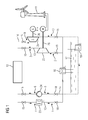
- FIG. 1 is a system to recognize, with the excess electrical energy of a wind power plant 11 can be converted into thermal energy, which can be stored in a heat storage 12.
- the heat storage can be made in a manner not shown, for example, from a cast concrete body in which a channel system is provided, which can be traversed by a working medium.
- the electrical energy of the wind power plant 11 is fed via a motor M in the system.
- the heat accumulator 12 can be discharged, which ultimately can be generated via a generator G electrical energy.
- a charging circuit 13 and a discharge circuit 14 are realized in the system. These consist of schematic shown lines in which a working fluid, such as ammonia, can circulate.
- valves 15 either the charging circuit 13 or the discharge circuit 14 is activated by a connection to the heat accumulator 12 is made. Furthermore, in the charging and discharging circuit, a first heat exchanger 16 is provided, which can be fed with river water of a schematically indicated flow 17. Also for the connection of the first heat exchanger 16 valves 18 are provided so that it can be used in the charging circuit 13 and the discharge circuit 14 for use. Instead of the valves 18, as shown in phantom, a second heat exchanger 19 can be used. In the field of heat exchangers arise in this way two separate circuits for charging circuit 13 and discharge circuit 14, as in FIG. 1 indicated, which makes the valves 18 unnecessary.
- the respective flow directions of the charging circuit 13 and the discharge circuit 14 are indicated by arrows.
- characteristic positions are indicated by numbers between 1 to 10, wherein these characteristic positions of the expiring Rankine processes also in the FIGS. 2 and 3 can be seen. These should explain the process of the respective process in more detail below.
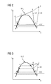
- a charge cycle 20 and a discharge cycle 21 are shown as they can be run through with ammonia as the working medium (R717).
- the working medium In position 1 of the cycle, the working medium is at a pressure of 5 bar.
- the boiling point of ammonia is 4 ° C.
- the heat from the river water at 15 ° C can be used to vaporize the working fluid in the first heat exchanger 16. This way you get to position 2.
- the working fluid by means of the motor M by a first fluid energy machine 22, which is connected as a hydrodynamic compressor, to a pressure of more than 131 bar, for example, 140 bar, brought. This heats up the working medium to 320 ° C and reaches position 3.
- This heat can then be entered into the material of the heat accumulator 12, wherein this acts as a heat exchanger.
- the working medium isobaric cooled to a temperature of less than 30 ° C, whereby position 4 of the cycle is achieved.
- a first throttle 23 the working fluid can be relaxed and reached in this way again a pressure of 5 bar.
- a turbine or the like is not required.
- the discharge cycle 21 proceeds as follows.
- the condensation pressure can be set at 10 bar, so that the boiling point of the working medium (also ammonia) at 25 ° C, ie above the temperature level of the flow at 15 ° C.
- liquid ammonia is present and is brought via a pump 24 to a supercritical pressure.
- the working fluid is warmed up and brought to the critical position 9.
- the present in the heat storage 12 temperature level can not be fully achieved. For example, heating to 220 ° C is possible.
- Mechanical energy can be obtained from the working medium in the supercritical state via a second fluid energy machine 25 in the form of a turbine, which energy is converted into electrical energy via the generator G.
- the mechanical connections between the generator G and the second fluid energy machine 25 and the motor M and the first fluid energy machine 22 are designed as shafts 26. After the expansion of the working medium, the position 10 is reached. The relaxed working medium is still gaseous and is condensed at 25 ° C, in which case the river water is warmed up.
- FIG. 3 a charge cycle 20 and a discharge cycle 21 is shown as this with a system according to FIG. 1 can be traversed using water.
- river water with a temperature of 15 ° C in the first heat exchanger should be used.
- a condensation pressure of 30 mbar is assumed.
- An evaporation temperature of the water of 5 ° C requires a pressure of 10 mbar. This results in the following parameters for the passage of the charging cycle. From position 1 to position 2, the water is evaporated at 10 mbar.
- Position 3 of the charge cycle is achieved by compressing the water vapor to 1 bar, with the temperature rising to about 540 ° C.
- the discharge cycle goes through the following positions.
- position 5 the water, which is now completely condensed at 30 mbar, has a temperature of 25 ° C.
- the pump 24 By means of the pump 24, the water is brought to a working pressure and transported through the heat accumulator 12, takes up heat and reaches position 7. Here it begins to boil while maintaining the temperature in position 7 until it is completely evaporated (position 8th). This is a subcritical evaporation of the water.
- the temperature level in the heat accumulator 12 then leads to an overheating of the water vapor to reach position 9 at about 480 ° C.
- the position 10 is achieved by the steam is relaxed via the second fluid energy machine 25, in this case, the water temperature reaches a temperature of 25 ° C again at a pressure of 30 mbar.
- the first heat exchanger 16 the water is then condensed again, whereby position 5 of the discharge cycle is achieved.
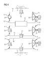
- FIG. 4 is another embodiment of the system shown. This differs from the embodiment according to FIG. 1 mainly because the charging cycle is divided into two stages.
- the heating of the heat accumulator 12 takes place in the charging circuit 13, which is different as in FIG. 1 completely separated from the discharge circuit 14.
- the charging circuit 13 with the first throttle 23, the heat accumulator 12 and the first fluid energy machine 22 and the discharge circuit with the pump 24, the heat accumulator 12, the second fluid energy machine 25 and the second heat exchanger 19 is analogous to FIG. 1 built up.
- the heat accumulator 12 has two independent channel systems each for the charging circuit and the Entladeniklauf in FIG. 4 are not shown in more detail.
- a third heat exchanger 27 is used in the charging circuit 13. This is not supplied by river water with ambient temperature for the purpose of heat exchange, but is connected to an additional circuit 28.
- the additional circuit 28 has the following function.
- a motor M2 is also provided, which drives a third fluid energy machine 29 via a shaft 26.
- This is provided in the additional circuit 29 and compresses the working fluid, such as carbon dioxide, which is heated thereby and the heat in the third heat exchanger 27 to the working fluid (for example, water) of the charging circuit 13 emits. Subsequently, the working fluid of the additional circuit 28 is expanded via a second throttle 30 and condensed via the first heat exchanger 16, which gives its heat to the flow 17.
- the positions 1 ', 2', 3 'and 4' are in FIG. 4 and give the characteristic positions of the Rankine process, which in FIG. 5 is shown.
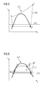
- This is an auxiliary charging cycle 20a, the first stage of the two-stage charging process according to FIG. 4 represents. From position 1 'to position 2', the carbon dioxide is evaporated, at a temperature of 5 ° C and a pressure of 40 bar. In this case, the necessary energy comes from the flow 17 and is entered via the first heat exchanger 16. About the third fluid energy machine 29 is the carbon dioxide compressed to 97 bar and reaches a temperature of 80 ° C (position 3 '). This heat can be delivered via the third heat exchanger 27 to the charging circuit 13, for which purpose a temperature window between 35 and 80 ° C is available. After cooling the working medium to 35 ° C to reach position 4 ', from where by relaxation of the carbon dioxide through the second throttle 30, a pressure of 40 bar is reached (position 1').
- the temperature level of 35 ° C in the third heat exchanger makes it possible to operate in the charging circuit 13 with water as a working fluid at a different level than in the case of FIG. 3 ,
- the condensation can be carried out at 30 mbar at a temperature of 25 ° C (position 10 to position 5). It is thus higher than in the case of FIG. 3 ,
- the discharge cycle analogous to the case according to FIG. 3 (Position 1 to position 2).
- the temperature level for the discharge cycle is thus still set by the flow 17 at 15 ° C.
- the method according to the invention is not limited to the working fluids limited in the exemplary embodiments.
- hydrocarbons such as propane can also be used.
- the charging circuit 13 and discharge circuit 14 according to FIG. 4 also according to FIG. 1 be realized with partially the same lines and valves 15, which in the heat exchanger 12 only a channel system must be provided.
- the second heat exchanger 19 in FIG. 1 required while the first heat exchanger 16 according to FIG. 1 would have to be replaced by the third heat exchanger 27 and the additional circuit 28 with all components.
Landscapes
- Engineering & Computer Science (AREA)
- Mechanical Engineering (AREA)
- General Engineering & Computer Science (AREA)
- Life Sciences & Earth Sciences (AREA)
- Sustainable Development (AREA)
- Sustainable Energy (AREA)
- Chemical & Material Sciences (AREA)
- Combustion & Propulsion (AREA)
- Power Engineering (AREA)
- Physics & Mathematics (AREA)
- Thermal Sciences (AREA)
- Engine Equipment That Uses Special Cycles (AREA)
Priority Applications (6)
| Application Number | Priority Date | Filing Date | Title |
|---|---|---|---|
| EP12164480.1A EP2653668A1 (fr) | 2012-04-17 | 2012-04-17 | Procédé de chargement et de déchargement d'un accumulateur thermique et installation pour le stockage et le dépôt d'énergie thermique appropriée à ce procédé |
| CN201380023586.7A CN104271896A (zh) | 2012-04-17 | 2013-03-28 | 用于蓄充和释放热存储器的方法和适合于此方法的存储和放出热能的设备 |
| US14/394,130 US20150075210A1 (en) | 2012-04-17 | 2013-03-28 | Method for charging and discharging a heat accumulator and plant for storing and releasing thermal energy, suitable for this method |
| EP13713849.1A EP2823156B1 (fr) | 2012-04-17 | 2013-03-28 | Installation pour le stockage et le dépôt d'énergie thermique |
| DK13713849.1T DK2823156T3 (da) | 2012-04-17 | 2013-03-28 | Anlæg til akkumulering og afgivelse af termisk energi |
| PCT/EP2013/056659 WO2013156291A1 (fr) | 2012-04-17 | 2013-03-28 | Procédé de charge et de décharge d'un accumulateur de chaleur et installation de stockage et de distribution d'énergie thermique appropriée pour ledit procédé |
Applications Claiming Priority (1)
| Application Number | Priority Date | Filing Date | Title |
|---|---|---|---|
| EP12164480.1A EP2653668A1 (fr) | 2012-04-17 | 2012-04-17 | Procédé de chargement et de déchargement d'un accumulateur thermique et installation pour le stockage et le dépôt d'énergie thermique appropriée à ce procédé |
Publications (1)
| Publication Number | Publication Date |
|---|---|
| EP2653668A1 true EP2653668A1 (fr) | 2013-10-23 |
Family
ID=48045500
Family Applications (2)
| Application Number | Title | Priority Date | Filing Date |
|---|---|---|---|
| EP12164480.1A Withdrawn EP2653668A1 (fr) | 2012-04-17 | 2012-04-17 | Procédé de chargement et de déchargement d'un accumulateur thermique et installation pour le stockage et le dépôt d'énergie thermique appropriée à ce procédé |
| EP13713849.1A Active EP2823156B1 (fr) | 2012-04-17 | 2013-03-28 | Installation pour le stockage et le dépôt d'énergie thermique |
Family Applications After (1)
| Application Number | Title | Priority Date | Filing Date |
|---|---|---|---|
| EP13713849.1A Active EP2823156B1 (fr) | 2012-04-17 | 2013-03-28 | Installation pour le stockage et le dépôt d'énergie thermique |
Country Status (5)
| Country | Link |
|---|---|
| US (1) | US20150075210A1 (fr) |
| EP (2) | EP2653668A1 (fr) |
| CN (1) | CN104271896A (fr) |
| DK (1) | DK2823156T3 (fr) |
| WO (1) | WO2013156291A1 (fr) |
Cited By (5)
| Publication number | Priority date | Publication date | Assignee | Title |
|---|---|---|---|---|
| WO2015131940A1 (fr) * | 2014-03-05 | 2015-09-11 | Siemens Aktiengesellschaft | Installation de stockage d'énergie à haute température et procédé de fonctionnement associé |
| WO2017055505A1 (fr) * | 2015-09-30 | 2017-04-06 | Siemens Aktiengesellschaft | Système d'échange de chaleur doté d'un dispositif de mouvement de fluide actif de joint pour le mode de charge et pour le mode de décharge et procédé d'échange de chaleur en utilisant le système d'échange de chaleur |
| WO2022112063A1 (fr) | 2020-11-30 | 2022-06-02 | Man Energy Solutions Se | Système et procédé de stockage d'énergie électrique sous forme d'énergie thermique et de libération de celle-ci |
| DE102021112050A1 (de) | 2021-05-07 | 2022-11-10 | Deutsches Zentrum für Luft- und Raumfahrt e.V. | Verfahren zum Betreiben einer Speicheranlage, Speicheranlage, Steuerungsprogramm und computerlesbares Medium |
| DE102022211960A1 (de) | 2022-11-11 | 2024-05-16 | Siemens Energy Global GmbH & Co. KG | Kombianlage und Verfahren zum Betreiben einer Kombianlage |
Families Citing this family (6)
| Publication number | Priority date | Publication date | Assignee | Title |
|---|---|---|---|---|
| EP2992207B1 (fr) * | 2013-04-29 | 2018-07-18 | Vestas Wind Systems A/S | Procédé de démarrage d'une éolienne dans un environnement climatique froid |
| GB201310717D0 (en) * | 2013-06-16 | 2013-07-31 | Garvey Seamus D | Direct-drive power conversion system for wind turbines compatible with energy storage |
| TN2016000008A1 (en) * | 2015-02-04 | 2017-07-05 | General Electric Technology Gmbh | Electrical energy storage and discharge system |
| US9394807B1 (en) | 2015-03-16 | 2016-07-19 | Sten Kreuger | Apparatus, system, and methods for mechanical energy regeneration |
| CN105840258A (zh) * | 2016-04-18 | 2016-08-10 | 西安交通大学 | 一种风能、燃气及超临界二氧化碳能源梯级利用联合发电系统 |
| WO2020097714A1 (fr) * | 2018-11-13 | 2020-05-22 | Lochterra Inc. | Systèmes et procédés pour la capture de l'énergie thermique, le transport à longue distance, le stockage et la distribution de l'énergie thermique capturée et de l'énergie générée à partir de ceux-ci |
Citations (6)
| Publication number | Priority date | Publication date | Assignee | Title |
|---|---|---|---|---|
| US4192144A (en) * | 1977-01-21 | 1980-03-11 | Westinghouse Electric Corp. | Direct contact heat exchanger with phase change of working fluid |
| WO1992014054A1 (fr) * | 1991-02-12 | 1992-08-20 | SØRENSEN, Anna, Margrethe | Systeme a eolienne de production et d'accumulation d'energie |
| US5384489A (en) * | 1994-02-07 | 1995-01-24 | Bellac; Alphonse H. | Wind-powered electricity generating system including wind energy storage |
| DE19921336A1 (de) * | 1999-05-08 | 2000-12-07 | Holder K | Thermisches Kraftwerk |
| WO2009044139A2 (fr) | 2007-10-03 | 2009-04-09 | Isentropic Limited | Stockage d'énergie |
| WO2011036738A1 (fr) * | 2009-09-24 | 2011-03-31 | 株式会社 日立製作所 | Système de génération de puissance à pompe à chaleur |
Family Cites Families (2)
| Publication number | Priority date | Publication date | Assignee | Title |
|---|---|---|---|---|
| EP2241737B1 (fr) * | 2009-04-14 | 2015-06-03 | ABB Research Ltd. | Système de stockage d'énergie thermoélectrique doté de deux réservoirs thermiques et procédé de stockage d'énergie thermoélectrique |
| TW201300639A (zh) * | 2011-06-22 | 2013-01-01 | Univ Nat Pingtung Sci & Tech | 以低溫熱源推動之動力系統 |
-
2012
- 2012-04-17 EP EP12164480.1A patent/EP2653668A1/fr not_active Withdrawn
-
2013
- 2013-03-28 WO PCT/EP2013/056659 patent/WO2013156291A1/fr active Application Filing
- 2013-03-28 US US14/394,130 patent/US20150075210A1/en not_active Abandoned
- 2013-03-28 DK DK13713849.1T patent/DK2823156T3/da active
- 2013-03-28 EP EP13713849.1A patent/EP2823156B1/fr active Active
- 2013-03-28 CN CN201380023586.7A patent/CN104271896A/zh active Pending
Patent Citations (8)
| Publication number | Priority date | Publication date | Assignee | Title |
|---|---|---|---|---|
| US4192144A (en) * | 1977-01-21 | 1980-03-11 | Westinghouse Electric Corp. | Direct contact heat exchanger with phase change of working fluid |
| WO1992014054A1 (fr) * | 1991-02-12 | 1992-08-20 | SØRENSEN, Anna, Margrethe | Systeme a eolienne de production et d'accumulation d'energie |
| US5436508A (en) | 1991-02-12 | 1995-07-25 | Anna-Margrethe Sorensen | Wind-powered energy production and storing system |
| US5384489A (en) * | 1994-02-07 | 1995-01-24 | Bellac; Alphonse H. | Wind-powered electricity generating system including wind energy storage |
| DE19921336A1 (de) * | 1999-05-08 | 2000-12-07 | Holder K | Thermisches Kraftwerk |
| WO2009044139A2 (fr) | 2007-10-03 | 2009-04-09 | Isentropic Limited | Stockage d'énergie |
| WO2011036738A1 (fr) * | 2009-09-24 | 2011-03-31 | 株式会社 日立製作所 | Système de génération de puissance à pompe à chaleur |
| EP2482002A1 (fr) * | 2009-09-24 | 2012-08-01 | Hitachi, Ltd. | Système de génération de puissance à pompe à chaleur |
Cited By (9)
| Publication number | Priority date | Publication date | Assignee | Title |
|---|---|---|---|---|
| WO2015131940A1 (fr) * | 2014-03-05 | 2015-09-11 | Siemens Aktiengesellschaft | Installation de stockage d'énergie à haute température et procédé de fonctionnement associé |
| WO2017055505A1 (fr) * | 2015-09-30 | 2017-04-06 | Siemens Aktiengesellschaft | Système d'échange de chaleur doté d'un dispositif de mouvement de fluide actif de joint pour le mode de charge et pour le mode de décharge et procédé d'échange de chaleur en utilisant le système d'échange de chaleur |
| CN108139170A (zh) * | 2015-09-30 | 2018-06-08 | 西门子股份公司 | 具有用于充能模式并用于放能模式的共同的主动流体运动装置的热交换系统和通过使用热交换系统用于交换热的方法 |
| US11015488B2 (en) | 2015-09-30 | 2021-05-25 | Siemens Gamesa Renewable Energy A/S | Heat exchange system with a joint active fluid motion device for the charging mode and for the discharging mode and method for exchanging heat by using the heat exchange system |
| WO2022112063A1 (fr) | 2020-11-30 | 2022-06-02 | Man Energy Solutions Se | Système et procédé de stockage d'énergie électrique sous forme d'énergie thermique et de libération de celle-ci |
| DE102020131706A1 (de) | 2020-11-30 | 2022-06-02 | Man Energy Solutions Se | System und Verfahren zur Speicherung und Abgabe von elektrischer Energie mit deren Speicherung als Wärmeenergie |
| DE102021112050A1 (de) | 2021-05-07 | 2022-11-10 | Deutsches Zentrum für Luft- und Raumfahrt e.V. | Verfahren zum Betreiben einer Speicheranlage, Speicheranlage, Steuerungsprogramm und computerlesbares Medium |
| WO2022233582A2 (fr) | 2021-05-07 | 2022-11-10 | Deutsches Zentrum für Luft- und Raumfahrt e.V. | Procédé pour faire fonctionner une installation de stockage, installation de stockage, programme de commande et support lisible par ordinateur |
| DE102022211960A1 (de) | 2022-11-11 | 2024-05-16 | Siemens Energy Global GmbH & Co. KG | Kombianlage und Verfahren zum Betreiben einer Kombianlage |
Also Published As
| Publication number | Publication date |
|---|---|
| US20150075210A1 (en) | 2015-03-19 |
| EP2823156A1 (fr) | 2015-01-14 |
| WO2013156291A1 (fr) | 2013-10-24 |
| EP2823156B1 (fr) | 2021-11-03 |
| DK2823156T3 (da) | 2022-01-10 |
| CN104271896A (zh) | 2015-01-07 |
Similar Documents
| Publication | Publication Date | Title |
|---|---|---|
| EP2823156B1 (fr) | Installation pour le stockage et le dépôt d'énergie thermique | |
| EP2748434B1 (fr) | Installation de stockage d'énergie thermique | |
| EP2686526B1 (fr) | Procédé pour faire fonctionner un processus à circuit de vapeur | |
| WO2014026863A2 (fr) | Procédé de charge et de décharge d'un accumulateur de chaleur et installation permettant l'accumulation et la distribution d'énergie thermique, adaptée au procédé de charge et de décharge d'un accumulateur de chaleur | |
| DE102007041457A1 (de) | Verfahren und Vorrichtung zur Umwandlung der Wärmeenergie einer Niedertemperatur-Wärmequelle in mechanische Energie | |
| DE102010033659A1 (de) | Verfahren und Vorrichtung zur Energierückgewinnung aus einem Abgasstrom eines Verbrennungsmotors in einem Fahrzeug | |
| DE102015109898A1 (de) | Dampfkraftwerk und Verfahren zu dessen Betrieb | |
| EP3006682B1 (fr) | Dispositif et procédé de fonctionnement d'une station de transmission thermique | |
| EP2825737A1 (fr) | Installation d'accumulation et de distribution d'énergie thermique au moyen d'un accumulateur de chaleur et d'un accumulateur de froid et procédé de fonctionnement de ladite installation | |
| WO2014044549A2 (fr) | Procédé de charge et décharge d'un milieu accumulateur dans un accumulateur thermique et installation de mise en œuvre de ce procédé | |
| DE102010004079A1 (de) | Brennkraftmaschine, kombiniert mit Rankineprozess zur effizienten Nutzung der Kühlmittel- und Abgaswärme | |
| DE10055202A1 (de) | Dampfkraft-/Arbeitsprozeß mit erhöhtem mechanischen Wirkungsgrad für die Elektroenergiegewinnung im Kreisprozeß sowie Anordnung zu seiner Durchführung | |
| WO2010029020A1 (fr) | Machine motrice et procédé de fonctionnement d'une machine motrice | |
| WO2022112063A1 (fr) | Système et procédé de stockage d'énergie électrique sous forme d'énergie thermique et de libération de celle-ci | |
| DE102012110579B4 (de) | Anlage und Verfahren zur Erzeugung von Prozessdampf | |
| WO2011045047A2 (fr) | Procédé à cycle (o)rc pour la transformation en énergie électrique de la chaleur produite lors de la combustion de biomasse et dispositif correspondant | |
| DE102010036530A1 (de) | Wärmekraftmaschine zur Umwandlung von Wärmeenergie in mechanische Energie, die zur Erzeugung von Strom benutzt wird, sowie Verfahren zum Betrieb einer solchen Wärmekraftmaschine | |
| EP3559564B1 (fr) | Procédé et dispositif de production de froid de processus et de vapeur de processus | |
| DE102009024776A1 (de) | Fahrzeug mit einem geschlossenen Fluidkreislauf | |
| WO2018029371A1 (fr) | Échangeur de chaleur destiné à être utilisé dans une partie chaude d'une centrale de stockage d'énergie par air liquide, partie chaude et procédé permettant de faire fonctionner ledit échangeur de chaleur dans ladite partie chaude | |
| DE102011075557A1 (de) | Leitungskreis und Verfahren zum Betreiben eines Leitungskreises zur Abwärmenutzung einer Brennkraftmaschine | |
| DE102015119531A1 (de) | Anordnung und Verfahren zur Rückgewinnung von Energie aus der Abwärme mindestens einer Brennkraftmaschine | |
| WO2014117924A2 (fr) | Procédé permettant de faire fonctionner une centrale basse température et centrale basse température | |
| DE102018209204A1 (de) | Betriebsverfahren für einen Turbosatz, Turbosatz und Niederdruckdampfturbinenanlage | |
| DE102017223705A1 (de) | Kraftwerk |
Legal Events
| Date | Code | Title | Description |
|---|---|---|---|
| PUAI | Public reference made under article 153(3) epc to a published international application that has entered the european phase |
Free format text: ORIGINAL CODE: 0009012 |
|
| AK | Designated contracting states |
Kind code of ref document: A1 Designated state(s): AL AT BE BG CH CY CZ DE DK EE ES FI FR GB GR HR HU IE IS IT LI LT LU LV MC MK MT NL NO PL PT RO RS SE SI SK SM TR |
|
| AX | Request for extension of the european patent |
Extension state: BA ME |
|
| STAA | Information on the status of an ep patent application or granted ep patent |
Free format text: STATUS: THE APPLICATION IS DEEMED TO BE WITHDRAWN |
|
| 18D | Application deemed to be withdrawn |
Effective date: 20140424 |