EP2653646B1 - Stacking unit of slats on support half-ladders for the production of venetian blinds and combined application method of hooks and half-ladders to a slat - Google Patents
Stacking unit of slats on support half-ladders for the production of venetian blinds and combined application method of hooks and half-ladders to a slat Download PDFInfo
- Publication number
- EP2653646B1 EP2653646B1 EP12195106.5A EP12195106A EP2653646B1 EP 2653646 B1 EP2653646 B1 EP 2653646B1 EP 12195106 A EP12195106 A EP 12195106A EP 2653646 B1 EP2653646 B1 EP 2653646B1
- Authority
- EP
- European Patent Office
- Prior art keywords
- aperture
- slat
- cavity
- matrix
- stacking unit
- Prior art date
- Legal status (The legal status is an assumption and is not a legal conclusion. Google has not performed a legal analysis and makes no representation as to the accuracy of the status listed.)
- Active
Links
Images








Classifications
-
- E—FIXED CONSTRUCTIONS
- E06—DOORS, WINDOWS, SHUTTERS, OR ROLLER BLINDS IN GENERAL; LADDERS
- E06B—FIXED OR MOVABLE CLOSURES FOR OPENINGS IN BUILDINGS, VEHICLES, FENCES OR LIKE ENCLOSURES IN GENERAL, e.g. DOORS, WINDOWS, BLINDS, GATES
- E06B9/00—Screening or protective devices for wall or similar openings, with or without operating or securing mechanisms; Closures of similar construction
- E06B9/24—Screens or other constructions affording protection against light, especially against sunshine; Similar screens for privacy or appearance; Slat blinds
- E06B9/26—Lamellar or like blinds, e.g. venetian blinds
- E06B9/266—Devices or accessories for making or mounting lamellar blinds or parts thereof
-
- E—FIXED CONSTRUCTIONS
- E06—DOORS, WINDOWS, SHUTTERS, OR ROLLER BLINDS IN GENERAL; LADDERS
- E06B—FIXED OR MOVABLE CLOSURES FOR OPENINGS IN BUILDINGS, VEHICLES, FENCES OR LIKE ENCLOSURES IN GENERAL, e.g. DOORS, WINDOWS, BLINDS, GATES
- E06B9/00—Screening or protective devices for wall or similar openings, with or without operating or securing mechanisms; Closures of similar construction
- E06B9/24—Screens or other constructions affording protection against light, especially against sunshine; Similar screens for privacy or appearance; Slat blinds
- E06B9/26—Lamellar or like blinds, e.g. venetian blinds
- E06B9/28—Lamellar or like blinds, e.g. venetian blinds with horizontal lamellae, e.g. non-liftable
- E06B9/30—Lamellar or like blinds, e.g. venetian blinds with horizontal lamellae, e.g. non-liftable liftable
- E06B9/32—Operating, guiding, or securing devices therefor
- E06B9/323—Structure or support of upper box
Definitions
- the present invention relates to a stacking unit of slats on support half-ladders for the production of Venetian blinds, as well as to a combined application method of hooks and half-ladders to a slat.
- Venetian blinds are composed of a plurality of slats, positioned parallel to each other and held in position by means of cord support structures. Such structures are essentially of two types.
- a first type of structure is called a "full ladder", that is to say composed of two parallel ribs (positioned in the height-wise direction of the blind) and by a plurality of cross-members which connect them to each other at regular intervals.
- a slat is associated to each cross-member, resting thereon (if the cross-member is single) or inserted therein if the cross-member is multiple.
- a relevant stacking unit is known from EP 2253794 A2 .
- a second type of structure is called a "separated ladders" or "half-ladder”, that is to say is composed of two cords separate from each other and each provided with a plurality of string eyelets distributed at regular distances along the single cord.
- the support cords are positioned in pairs at opposite sides of the slats, generally transversally aligned.
- the cords are associated to the slats in correspondence with the eyelets by means of staples or hooks fixed to the lateral rims thereof.
- the slats which may have any cross-section, such as a C, Z or S-shape, must have bent rims (as shown in Figure 1 ) so as to constitute a reinforced zone able to rigidly support a hook or a staple.
- the staples are attachment elements structured to block a single eyelet directly in contact with the rim of the slat.
- the eyelet is positioned between the slat and the staple. Generally this operation is performed manually with the help of a staple gun to apply the staples.
- the hooks may be of many types, but all characterised by the fact that the eyelet is blocked directly onto the hook and not onto the slat.
- FIG. 2 One type of widely diffused hook is shown in Figure 2 and is composed of a U-element, which defines the anchorage portion to the slat, and by an open ring, which extends from the U-element in a position opposite to the two free ends of the U and in correspondence with which the eyelet is inserted. The open ring is then closed after inserting the eyelet.
- Such devices for automatically applying the U-hooks with rings to the rims of the slats are known, see, e.g. US 4606099 A . More in detail, such devices consists of a central guide which the slat slides along. Laterally to such guide a matrix is positioned on each side to block the bent rim of the slat. Said matrix is composed of two coupled parts, suitable for opening, which enclose the rim of the slat between them as in a vice in a suitably shaped seat. A thrust element and a hook feeder are associated to each matrix. The thrust element is guided to enter inside the inner seat of the matrix bearing in front of it a single hook to apply to the rim. The hooks are positioned in front of the head of the thrust element by means of a chute connected to the feeder.
- Such application devices may be inserted in-line on a production plant (profiling, punching, etc.) of the slats.
- the application of the hooks is slower than the production and machining operations of the slats and becomes the bottleneck of the process. In-line configuration is therefore only acceptable in plants sized for small production lots.
- the purpose of the present invention is to eliminate entirely or in part the drawbacks of the prior art mentioned above, by making available a unit for stacking slats on support half-ladders for the production of Venetian blinds, which makes it possible to perform the operation of attaching the hooks to the slats and the operation of coupling the half-ladders to the hooks in a combined manner.
- a further purpose of the present invention is to make available a unit for stacking slats on support half-ladders which is easy to operate.
- a further purpose of the present invention is to make available a unit for stacking slats on support half-ladders which is simple and economical to make.
- a further purpose of the present invention is to make available a combined application method of hooks and half-ladders to a slat which permits the two operations to be combined in a simple and reliable manner.
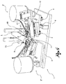
- reference numeral 1 globally denotes a stacking unit of slats on support half-ladders for the production of Venetian blinds according to the invention.
- the stacking unit 1 makes it possible to perform the operation of attaching the hooks to the slat and the operation of coupling the half-ladders to the hooks in a combined manner.
- a half-ladder S' of the known type having a longitudinal rib P from which eyelets O extend positioned at a regular intervals.
- a hook G of the known type, an example of which is shown in Figure 2 , comprising an anchorage portion G1 to the slat L and an open ring G2, which extends in an opposite position to the coupling portion and destined to engage an eyelet O of a half-ladder.
- the anchorage portion is composed of two parallel appendages G1' and G1" which at the moment of anchorage get deformed to engage on the rim of the slat assuming the shape of hooks.
- the stacking unit 1 is destined to be associated to one or more identical units to constitute an assembling station of the Venetian blinds.
- the units 1 are moveably associated to a longitudinal support bar (not shown) along which the slats are made to slide.
- the units 1 may be repositioned along said bar to adapt to the length of the slats.
- Such assembling station may be placed in line with a slat production machine, or be placed off line so as not to slow down the faster slat production process.
- the stacking unit 1 comprises at least one group 2 for assembling on a slat L a hook G and a half-ladder S'. Said assembling group 2 being positioned laterally in relation to a longitudinal axis X along which the individual slats L slide to engage a longitudinal rim B of a slat L.
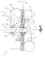
- the stacking unit comprises two assembling groups 2', 2" positioned on opposite sides of the longitudinal axis X to engage both longitudinal rims B of a slat L and thus permit the application of hooks and half-ladders contemporaneously on both sides of the slat.
- the single assembling group 2', 2" has an asymmetric structure with respect to a transversal direction to the axis X. Considering this asymmetric structure, it is preferable for the two assembling groups 2', 2" to be entirely identical. The arrangement of the two assembling groups in frontal positions opposite in relation to the longitudinal axis X permits however that the forces applied to the slat are balanced, reducing the risk of deformation thereof.
- each assembling group 2', 2" in turn comprises a matrix 11, 12 which defines a cavity 13 parallel to the longitudinal axis X to house a rim portion B of a slat.
- the matrix 11, 12 acts so as to retain the rim portion B of the slat in correspondence with which the hook G is to be applied, so as to absorb the impulsive force applied to the hook to permit the anchorage thereof and impose a bending of the anchorage appendages G1' and G1" against the rim of the slat after perforating it.
- the matrix is provided with suitable seats 13a in correspondence with the cavity 13 to guide the bending of such appendages.
- the matrix comprises a first 14 and a second 15 aperture of access to the cavity 13. Between two access apertures - parallel to the longitudinal direction X - a through aperture 16 is made in said matrix. The function of such apertures will be described below.
- the matrix is divided into two portions: a lower portion 11, which is positioned under the rim B of the slat, and an upper portion 12, which is positioned above such rim B.
- the aforesaid cavity 13 is made at the interface between said two portions 11 and 12.
- the first 14 and the second aperture 15 are made in the upper portion 12.
- the through aperture 16 may cross both portions in a direction which is incident to the interface surface or only to the upper portion 12.
- the two portions of the matrix overlap at least partially and the two access apertures to the cavity are also made at the interface between the two portions.
- the two portions 11, 12 of the matrix are movable in relation to one another between an adjacent position, in which they hold the rim portion B of the slat L between them in a vice, in correspondence with the cavity 13, and at least one partially separated position, wherein said two portions are distanced from one another to widen the cavity 13 in transversal direction, so as to permit the relative sliding of the ring G2 of a hook G anchored to the rim B inside the cavity.
- the partial separation of the two portions aims to permit the sliding of said ring from the first aperture 14 as far as the second aperture 15, passing through the through aperture 16.
- such two portions 11, 12 of the matrix can be moved away from each other beyond said partially separated position to reach a completely separated position, in which the two portions 11, 12 of the matrix are distanced from each other to completely free the rim B of the slat and a hook G associated to it, from the cavity 13, and thereby permit the distancing of the slat (with hook and half-ladder associated to it) from the assembling group 2', 2".
- the two portions 11 and 12 of the matrix are movable by means of actuators 17, consisting for example of electric, pneumatic or hydraulic pistons.
- each assembling group 2', 2" comprises a device 10, 31 for applying hooks G to the rim B of a slat L in correspondence with the first aperture 14.
- Said application device 10, 31 positions the individual hook G on the rim B with the anchorage portion G1 engaged on said rim and with the ring G2 positioned inside the cavity 13 of the matrix.
- the hook application device 10 comprises a hook G feeder 20, which by means of a chute 21 positions one hook at a time on the matrix 13 next to the first aperture 14.
- the feeder may be of the stacking or vibrational type and permits feeding of the hooks G positioning them with the anchorage portion G1 facing towards the first aperture 14 and with the ring aperture G2 facing towards the second aperture 15 transversally (i.e. parallel to the longitudinal direction X).
- the application device 10 comprises a first thrust element 31 movable along a first working direction Y1, incident to the rim B, between:
- the first thrust element 31 slides inside a guide 34, in correspondence with which the exit of the feeder chute 21 is placed.
- the thrust element 31 acts as a regulator element of the descent movement of the hooks from the chute. In particular, when the end tip of the thrust element 31 occupies the guide 34 passing beyond the exit of the chute 21, the descent of the hook is prevented.
- Each assembling group 2', 2" comprises:
- the guide device 40 comprises a linear guide 41 which retains within it in the aforesaid positioning direction Z the longitudinal rib P of the half-ladder S' , leaving an eyelet O on the outside at the point of the through aperture 16 and facing towards the inside of the cavity 13.
- the stacking unit 1 comprises means 4, 5 for generating a relative movement between the slat L and the matrix 13 parallel to the longitudinal direction X for a tract equivalent to the distance D between the first 14 and the second aperture 15.
- a ring G2 of a hook G - already anchored to the rim B by means of the application device 31 at the first aperture 14 - shifts along the cavity 13 from said first aperture 14 to the second aperture 15 crossing the through aperture 16.
- the open ring G2 engages the eyelet O positioned there and pulls it with itself as far as the second aperture 15, where the ring G2 with the eyelet O engaged inside it, is closed by the closure device 32.
- the portions of the matrix are brought into the aforesaid partially separated position.
- the aforesaid relative movement is obtained moving only the matrix and leaving the slat L still.
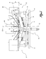
- said means for generating a movement consist of means 4, 5 of moving the assembling group 2 with respect to a fixed support structure 3 parallel to the longitudinal direction X.
- the stacking unit 1 comprises a fixed support structure 3.
- a movable support plate 5 is moveably connected to this fixed structure 3 by means of guides 4 parallel to the longitudinal direction X.
- the moveable support plate 5 supports a single assembling group 2. The movement of the plate 5 and of the group associated thereto is performed by means of one or more dedicated actuators 6.
- the closure device comprises a second thrust element 32 movable along a second working direction Y2, incident to the rim B or passing next to it, between a thrust position, in which it engages the cavity 13 of the matrix passing through the second aperture 15, and a release position, in which it does not engage the cavity 13.
- the two working directions Y1 and Y2 of the two thrust elements are parallel and coplanar to each other.
- the two thrust elements 31, 32 are moved by a common actuator 33 between the thrust and release positions.
- a sliding plane m of the individual slat L may be defined, in correspondence with which plane the slat L is supported with both its longitudinal rims B.
- the common lying plane n of the two working directions Y1, Y2 is angled with respect to said sliding plane m by an angle a. Operatively, this facilitates the insertion of the hooks in the rim B.
- the head portion 32a of the second thrust element 32 has a seat shaped so that the thrust action is concentrated on the ring, deforming it.
- the head portion 32a of the first thrust element 32 has a seat shaped so that the ring may be entirely housed therein and the thrust applied to the sides of the ring, in correspondence with the base of the anchorage portion G1.
- the guide device 40 of the half-ladder S' comprises means of positioning a single eyelet O of the half-ladder S' in correspondence with the through aperture 16 of the matrix.
- the guide device 40 comprises means of moving the half-ladder S' in the linear guide 41 according to a way of advancement A along the positioning direction Z to progressively bring each eyelet O in correspondence with the through aperture 16.
- the positioning means comprise at least one sensor (not shown; preferably of the optical type) to detect the transit before it of an eyelet during a movement of the half-ladder along the positioning direction Z.
- the sensor faces onto the through aperture 16 at a predefined distance H from the cavity 13 with respect to the positioning direction Z.
- the eyelet O is positionable in correspondence with the cavity 13 operating the movement means to move the half-ladder by a tract equivalent to the aforesaid predefined distance H along the positioning direction Z at the moment in which the sensor detects the passage of an eyelet O.
- mechanical type positioning means comprising for example mechanical abutments and vertical tensioning systems of the half-ladder (for example by means of weights).
- the guide device 40 of the half-ladder S' comprises means of retaining the half-ladder S' in the linear guide 41.
- Such means may be manually adjustable frictioning elements, or frictioning systems controlled remotely which may also completely block the half-ladder inside the guide.
- the stacking unit 1 comprises at least one slat loader 60.
- the loader may be of any type suitable for the purpose.
- the loader 60 may be composed of two bars 61 and 62 provided with sprung teeth for the positioning of the slats already inserted in the half-ladder.
- the stacking unit 1 comprises means 60 of moving a slat L from a position for applying hooks and half-ladders to a dropping position into the loader.
- the movement of the slat L makes the half-ladder S' associated to it advance pulling it into the guide device 40.
- Such means of movement of the half-ladder may consist for example of a hoist 30, comprising a pneumatic, hydraulic or electric cylinder.
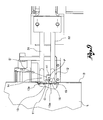
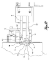
- the matrix is shown with the two portions 11 and 12 completely separate; the slat L has just been positioned; the half-ladder is already positioned with an eyelet in the through aperture 16 in correspondence with the cavity 13.
- the two portions of the matrix are closed and a hook G is positioned next to the first aperture 14 ( Figure 10 ).
- the first thrust element 31 has been activated (together with the second thrust element 32 which runs idle) and the hook is anchored to the rim.
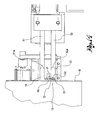
- the two portions 11 and 12 of the matrix are partially separated ( Figure 12 ) and the entire assembling group 2 is moved parallel to the direction X: the already anchored hook passes with the ring G2 from the first aperture 14 to the second aperture 15 passing through the through aperture 16 where it engages the eyelet O pulling it with itself ( Figure 13 ).
- the matrix is then closed again completely ( Figure 14 ) and the second thrust element 32 is then activated (together with the first thrust element 31 which runs idle) with closing of the ring.
- the half-ladder is now associated to the hook.
- the matrix can be opened and the slat moves upwards inside the loader pulling the half-ladder with itself.
- the present invention also relates to a method of positioning a support half-ladder (comprising a plurality of pairs of cross-members T1, T2) for the production of Venetian blinds.
- the method is applied to a stacking unit 1 according to the present invention.
- the method comprises the following operating steps:
- the aforesaid operating steps are cyclically repeated on each slat which is inserted in the stacking unit and associated by the half-ladder S' to the slat preceding it.
- the stacking unit 1 comprises two matrixes 11, 12, positioned laterally to the longitudinal axis X in opposite positions, each housing a portion of the two opposite rims of a slat.
- the operating steps from b) to d) of the method being performed at both matrixes for the two opposite rims. This way the hooks and relative half-ladders are applied to both sides of the slat contemporarily.
- the invention permits numerous advantages to be obtained, in part already described.
- the stacking unit 1 makes it possible to perform the operation of attaching the hooks to the slat and the operation of coupling the half-ladders to the hooks in a combined manner. Such operations may therefore be conducted in the same station with a reduction of downtime, but also with a simpler plant design. The insertion of the half-ladders no longer requires a dedicated station.
- the stacking unit of slats on support half-ladders is easy to manage, for example by means of a normal PLC.
- the stacking unit is also simple and economical to produce, given that it makes use of device at least in part already present on the market, such as the hook application device (without closing of the ring).
- the slat is balanced as regards the forces applied during the anchorage of the hooks and the closing of the rings.
- the invention thus conceived thereby achieves the predefined aims.
Landscapes
- Engineering & Computer Science (AREA)
- Structural Engineering (AREA)
- Architecture (AREA)
- Civil Engineering (AREA)
- Blinds (AREA)
- Plural Heterocyclic Compounds (AREA)
Priority Applications (3)
| Application Number | Priority Date | Filing Date | Title |
|---|---|---|---|
| SI201230109T SI2653646T1 (sl) | 2012-03-02 | 2012-11-30 | Enota za kopičenje lamel na nosilnih polovičnih lestvah za proizvodnjo žaluzij in kombiniran postopek apliciranja kavljev in polovičnih lestev na lamelo |
| PL12195106T PL2653646T3 (pl) | 2012-03-02 | 2012-11-30 | Urządzenie do układania listew na półdrabinach nośnych do wytwarzania żaluzji z łat drewnianych oraz wspólny sposób mocowania haków i półdrabin do listwy |
| HRP20141167AT HRP20141167T1 (hr) | 2012-03-02 | 2014-12-02 | Uređaj za slaganje lamela od polu-ljestve za proizvodnju venecijaner zavjesa i kombinirani postupak postavljanja kuka i polu-ljestvi na lamelu |
Applications Claiming Priority (1)
| Application Number | Priority Date | Filing Date | Title |
|---|---|---|---|
| IT000061A ITPD20120061A1 (it) | 2012-03-02 | 2012-03-02 | Unità di impilatura di lamelle su semiscalette di sostegno per la produzione di tende veneziane e metodo di applicazione combinata di ganci e di semiscalette ad una lamella |
Publications (3)
| Publication Number | Publication Date |
|---|---|
| EP2653646A2 EP2653646A2 (en) | 2013-10-23 |
| EP2653646A3 EP2653646A3 (en) | 2013-12-25 |
| EP2653646B1 true EP2653646B1 (en) | 2014-09-17 |
Family
ID=46022547
Family Applications (1)
| Application Number | Title | Priority Date | Filing Date |
|---|---|---|---|
| EP12195106.5A Active EP2653646B1 (en) | 2012-03-02 | 2012-11-30 | Stacking unit of slats on support half-ladders for the production of venetian blinds and combined application method of hooks and half-ladders to a slat |
Country Status (9)
| Country | Link |
|---|---|
| EP (1) | EP2653646B1 (sr) |
| DK (1) | DK2653646T3 (sr) |
| ES (1) | ES2525271T3 (sr) |
| HR (1) | HRP20141167T1 (sr) |
| IT (1) | ITPD20120061A1 (sr) |
| PL (1) | PL2653646T3 (sr) |
| PT (1) | PT2653646E (sr) |
| RS (1) | RS53699B1 (sr) |
| SI (1) | SI2653646T1 (sr) |
Cited By (1)
| Publication number | Priority date | Publication date | Assignee | Title |
|---|---|---|---|---|
| EP3409874A1 (en) | 2017-05-31 | 2018-12-05 | Dallan S.p.A. | Station for assembling venetian blinds |
Families Citing this family (6)
| Publication number | Priority date | Publication date | Assignee | Title |
|---|---|---|---|---|
| ITPD20130354A1 (it) * | 2013-12-20 | 2015-06-21 | Dallan Spa | Unità di impilatura di lamelle su una scaletta di sostegno con traversi doppi per la produzione di tende veneziane e metodo di fissaggio di lamelle su una scaletta con traversi doppi |
| EP2905415B1 (en) | 2014-02-07 | 2018-06-27 | Dallan S.p.A. | Device and method for applying hooks or clips to the slats of venetian blinds with folded edges provided with abutment gaskets |
| PL2990583T3 (pl) | 2014-08-29 | 2017-10-31 | Dallan Spa | Urządzenie do układania listewek żaluzji poziomych na konstrukcji wsporczej i sposób ustawiania konstrukcji wsporczej w urządzeniu do układania listewek |
| CZ307302B6 (cs) * | 2016-10-24 | 2018-05-23 | Zebr S.R.O. | Univerzální nýtovací jednotka pro usazování vodicích čepů na lamely venkovních žaluzií |
| IT201800004958A1 (it) | 2018-04-27 | 2019-10-27 | Unità di impilatura di lamelle su una scaletta di sostegno per la produzione di tende veneziane e metodo di impilatura di lamelle su una scaletta di sostegno | |
| JP7137694B2 (ja) | 2018-09-12 | 2022-09-14 | シェンチェン ショックス カンパニー リミテッド | 複数の音響電気変換器を有する信号処理装置 |
Family Cites Families (2)
| Publication number | Priority date | Publication date | Assignee | Title |
|---|---|---|---|---|
| CH658881A5 (de) * | 1983-03-24 | 1986-12-15 | Griesser Ag | Verfahren und einrichtung zur herstellung des panzers eines lamellenstores. |
| CZ2009322A3 (cs) * | 2009-05-21 | 2010-12-01 | Zebr S.R.O. | Zpusob rozhrnování žaluziového žebrícku žaluziových lamel a rozhrnovací zarízení k jeho provádení |
-
2012
- 2012-03-02 IT IT000061A patent/ITPD20120061A1/it unknown
- 2012-11-30 PT PT121951065T patent/PT2653646E/pt unknown
- 2012-11-30 PL PL12195106T patent/PL2653646T3/pl unknown
- 2012-11-30 ES ES12195106.5T patent/ES2525271T3/es active Active
- 2012-11-30 RS RS20140684A patent/RS53699B1/sr unknown
- 2012-11-30 EP EP12195106.5A patent/EP2653646B1/en active Active
- 2012-11-30 SI SI201230109T patent/SI2653646T1/sl unknown
- 2012-11-30 DK DK12195106.5T patent/DK2653646T3/da active
-
2014
- 2014-12-02 HR HRP20141167AT patent/HRP20141167T1/hr unknown
Cited By (1)
| Publication number | Priority date | Publication date | Assignee | Title |
|---|---|---|---|---|
| EP3409874A1 (en) | 2017-05-31 | 2018-12-05 | Dallan S.p.A. | Station for assembling venetian blinds |
Also Published As
| Publication number | Publication date |
|---|---|
| SI2653646T1 (sl) | 2015-01-30 |
| PT2653646E (pt) | 2014-11-03 |
| ES2525271T3 (es) | 2014-12-19 |
| RS53699B1 (sr) | 2015-04-30 |
| EP2653646A3 (en) | 2013-12-25 |
| HRP20141167T1 (hr) | 2015-01-16 |
| EP2653646A2 (en) | 2013-10-23 |
| DK2653646T3 (da) | 2014-10-20 |
| ITPD20120061A1 (it) | 2013-09-03 |
| PL2653646T3 (pl) | 2015-01-30 |
Similar Documents
| Publication | Publication Date | Title |
|---|---|---|
| EP2653646A2 (en) | Stacking unit of slats on support half-ladders for the production of venetian blinds and combined application method of hooks and half-ladders to a slat | |
| EP2063064B1 (en) | A window covering safety device | |
| EP2252760B1 (en) | Cellular window shade | |
| EP2677108B1 (en) | Unit for stacking slats on a support ladder provided with double cross-beams for the production of venetian blinds and method for positioning a ladder | |
| US4606099A (en) | Method and apparatus for manufacturing an armor shutter | |
| DE3442650A1 (de) | Klammervorrichtung | |
| EP1859977A2 (en) | Assembly for moving blinds and the like, particularly in motor vehicles | |
| JP6395090B2 (ja) | プレス・ブレーキにおいてツールをロックするロック・デバイス | |
| US5207261A (en) | Venetian blind | |
| EP2886781B1 (en) | Stacking unit of slats on a support ladder with double crossbeams for the production of venetian blinds and method of attaching slats to a ladder with double crossbeams | |
| CH653093A5 (de) | Rafflamellenstore. | |
| EP0133759B1 (en) | Apparatus and a method for assembling slats of a venetian blind | |
| AU2013288393A1 (en) | Unit for stacking slats on a support ladder with double crossbeams for the production of venetian blinds and method of insertion of slats on a ladder with double crossbeams | |
| US9915013B2 (en) | Shed forming device for a weaving machine | |
| EP3190870B1 (en) | Vertical growth guide reel | |
| EP1832177B1 (en) | Machine for stuffing a food product in a casing | |
| EP3561215B1 (en) | Stacking unit of slats on a support ladder for the production of venetian blinds and method of stacking slats on a support ladder | |
| EP3409874B1 (en) | Station for assembling venetian blinds | |
| DE2003304B1 (de) | Verfahren zum Herstellen von raffbaren Lamellenjalousien und Vorrichtung zur Durchfuehrung des Verfahrens | |
| KR102835828B1 (ko) | 곡선 구간 설치가 용이한 커튼용 가이드 | |
| EP2920397B1 (de) | Führungsanordnung für einen behang | |
| EP3530864B1 (en) | Assembly station of venetian blinds with complete support ladders | |
| EP2864569A1 (en) | Slat for venetian blinds, venetian blind and method for producing such venetian blind | |
| GB1114075A (en) | Improvements in or relating to a method and apparatus for assembling venetian blinds | |
| EP2905415B1 (en) | Device and method for applying hooks or clips to the slats of venetian blinds with folded edges provided with abutment gaskets |
Legal Events
| Date | Code | Title | Description |
|---|---|---|---|
| PUAI | Public reference made under article 153(3) epc to a published international application that has entered the european phase |
Free format text: ORIGINAL CODE: 0009012 |
|
| AK | Designated contracting states |
Kind code of ref document: A2 Designated state(s): AL AT BE BG CH CY CZ DE DK EE ES FI FR GB GR HR HU IE IS IT LI LT LU LV MC MK MT NL NO PL PT RO RS SE SI SK SM TR |
|
| AX | Request for extension of the european patent |
Extension state: BA ME |
|
| PUAL | Search report despatched |
Free format text: ORIGINAL CODE: 0009013 |
|
| AK | Designated contracting states |
Kind code of ref document: A3 Designated state(s): AL AT BE BG CH CY CZ DE DK EE ES FI FR GB GR HR HU IE IS IT LI LT LU LV MC MK MT NL NO PL PT RO RS SE SI SK SM TR |
|
| AX | Request for extension of the european patent |
Extension state: BA ME |
|
| RIC1 | Information provided on ipc code assigned before grant |
Ipc: E06B 9/266 20060101AFI20131115BHEP |
|
| 17P | Request for examination filed |
Effective date: 20140318 |
|
| RBV | Designated contracting states (corrected) |
Designated state(s): AL AT BE BG CH CY CZ DE DK EE ES FI FR GB GR HR HU IE IS IT LI LT LU LV MC MK MT NL NO PL PT RO RS SE SI SK SM TR |
|
| GRAP | Despatch of communication of intention to grant a patent |
Free format text: ORIGINAL CODE: EPIDOSNIGR1 |
|
| INTG | Intention to grant announced |
Effective date: 20140430 |
|
| GRAS | Grant fee paid |
Free format text: ORIGINAL CODE: EPIDOSNIGR3 |
|
| GRAA | (expected) grant |
Free format text: ORIGINAL CODE: 0009210 |
|
| STAA | Information on the status of an ep patent application or granted ep patent |
Free format text: STATUS: THE PATENT HAS BEEN GRANTED |
|
| RAP1 | Party data changed (applicant data changed or rights of an application transferred) |
Owner name: DALLAN S.P.A. |
|
| AK | Designated contracting states |
Kind code of ref document: B1 Designated state(s): AL AT BE BG CH CY CZ DE DK EE ES FI FR GB GR HR HU IE IS IT LI LT LU LV MC MK MT NL NO PL PT RO RS SE SI SK SM TR |
|
| REG | Reference to a national code |
Ref country code: GB Ref legal event code: FG4D |
|
| REG | Reference to a national code |
Ref country code: CH Ref legal event code: EP |
|
| REG | Reference to a national code |
Ref country code: IE Ref legal event code: FG4D |
|
| REG | Reference to a national code |
Ref country code: AT Ref legal event code: REF Ref document number: 687805 Country of ref document: AT Kind code of ref document: T Effective date: 20141015 |
|
| REG | Reference to a national code |
Ref country code: DK Ref legal event code: T3 Effective date: 20141014 |
|
| REG | Reference to a national code |
Ref country code: NL Ref legal event code: T3 |
|
| REG | Reference to a national code |
Ref country code: DE Ref legal event code: R096 Ref document number: 602012003139 Country of ref document: DE Effective date: 20141030 |
|
| REG | Reference to a national code |
Ref country code: CH Ref legal event code: NV Representative=s name: JACOBACCI AND PARTNERS SA, CH Ref country code: RO Ref legal event code: EPE |
|
| REG | Reference to a national code |
Ref country code: PT Ref legal event code: SC4A Free format text: AVAILABILITY OF NATIONAL TRANSLATION Effective date: 20141027 |
|
| REG | Reference to a national code |
Ref country code: SE Ref legal event code: TRGR |
|
| REG | Reference to a national code |
Ref country code: HR Ref legal event code: TUEP Ref document number: P20141167 Country of ref document: HR |
|
| REG | Reference to a national code |
Ref country code: ES Ref legal event code: FG2A Ref document number: 2525271 Country of ref document: ES Kind code of ref document: T3 Effective date: 20141219 |
|
| REG | Reference to a national code |
Ref country code: NO Ref legal event code: T2 Effective date: 20140917 |
|
| PGFP | Annual fee paid to national office [announced via postgrant information from national office to epo] |
Ref country code: LU Payment date: 20141121 Year of fee payment: 3 Ref country code: DK Payment date: 20141119 Year of fee payment: 3 |
|
| REG | Reference to a national code |
Ref country code: HR Ref legal event code: T1PR Ref document number: P20141167 Country of ref document: HR |
|
| REG | Reference to a national code |
Ref country code: GR Ref legal event code: EP Ref document number: 20140402130 Country of ref document: GR Effective date: 20141121 |
|
| PG25 | Lapsed in a contracting state [announced via postgrant information from national office to epo] |
Ref country code: LT Free format text: LAPSE BECAUSE OF FAILURE TO SUBMIT A TRANSLATION OF THE DESCRIPTION OR TO PAY THE FEE WITHIN THE PRESCRIBED TIME-LIMIT Effective date: 20140917 |
|
| PGFP | Annual fee paid to national office [announced via postgrant information from national office to epo] |
Ref country code: BG Payment date: 20141031 Year of fee payment: 3 Ref country code: GR Payment date: 20141125 Year of fee payment: 3 Ref country code: IE Payment date: 20141124 Year of fee payment: 3 Ref country code: NO Payment date: 20141215 Year of fee payment: 3 Ref country code: SE Payment date: 20141124 Year of fee payment: 3 Ref country code: SK Payment date: 20141127 Year of fee payment: 3 Ref country code: FI Payment date: 20141217 Year of fee payment: 3 |
|
| REG | Reference to a national code |
Ref country code: PL Ref legal event code: T3 |
|
| REG | Reference to a national code |
Ref country code: SK Ref legal event code: T3 Ref document number: E 17530 Country of ref document: SK |
|
| REG | Reference to a national code |
Ref country code: LT Ref legal event code: MG4D |
|
| PG25 | Lapsed in a contracting state [announced via postgrant information from national office to epo] |
Ref country code: CY Free format text: LAPSE BECAUSE OF FAILURE TO SUBMIT A TRANSLATION OF THE DESCRIPTION OR TO PAY THE FEE WITHIN THE PRESCRIBED TIME-LIMIT Effective date: 20140917 Ref country code: LV Free format text: LAPSE BECAUSE OF FAILURE TO SUBMIT A TRANSLATION OF THE DESCRIPTION OR TO PAY THE FEE WITHIN THE PRESCRIBED TIME-LIMIT Effective date: 20140917 |
|
| PGFP | Annual fee paid to national office [announced via postgrant information from national office to epo] |
Ref country code: HR Payment date: 20141202 Year of fee payment: 3 Ref country code: PT Payment date: 20141119 Year of fee payment: 3 Ref country code: RS Payment date: 20141031 Year of fee payment: 3 |
|
| PG25 | Lapsed in a contracting state [announced via postgrant information from national office to epo] |
Ref country code: EE Free format text: LAPSE BECAUSE OF FAILURE TO SUBMIT A TRANSLATION OF THE DESCRIPTION OR TO PAY THE FEE WITHIN THE PRESCRIBED TIME-LIMIT Effective date: 20140917 Ref country code: IS Free format text: LAPSE BECAUSE OF FAILURE TO SUBMIT A TRANSLATION OF THE DESCRIPTION OR TO PAY THE FEE WITHIN THE PRESCRIBED TIME-LIMIT Effective date: 20150117 |
|
| PGFP | Annual fee paid to national office [announced via postgrant information from national office to epo] |
Ref country code: RO Payment date: 20141110 Year of fee payment: 3 Ref country code: HU Payment date: 20141120 Year of fee payment: 3 |
|
| REG | Reference to a national code |
Ref country code: HU Ref legal event code: AG4A Ref document number: E022568 Country of ref document: HU |
|
| REG | Reference to a national code |
Ref country code: DE Ref legal event code: R026 Ref document number: 602012003139 Country of ref document: DE |
|
| PLBI | Opposition filed |
Free format text: ORIGINAL CODE: 0009260 |
|
| PG25 | Lapsed in a contracting state [announced via postgrant information from national office to epo] |
Ref country code: MC Free format text: LAPSE BECAUSE OF FAILURE TO SUBMIT A TRANSLATION OF THE DESCRIPTION OR TO PAY THE FEE WITHIN THE PRESCRIBED TIME-LIMIT Effective date: 20140917 |
|
| PGFP | Annual fee paid to national office [announced via postgrant information from national office to epo] |
Ref country code: MK Payment date: 20141130 Year of fee payment: 3 |
|
| 26 | Opposition filed |
Opponent name: ZEBR S.R.O. Effective date: 20150617 |
|
| PLAX | Notice of opposition and request to file observation + time limit sent |
Free format text: ORIGINAL CODE: EPIDOSNOBS2 |
|
| PLAF | Information modified related to communication of a notice of opposition and request to file observations + time limit |
Free format text: ORIGINAL CODE: EPIDOSCOBS2 |
|
| REG | Reference to a national code |
Ref country code: FR Ref legal event code: PLFP Year of fee payment: 4 |
|
| PLBB | Reply of patent proprietor to notice(s) of opposition received |
Free format text: ORIGINAL CODE: EPIDOSNOBS3 |
|
| REG | Reference to a national code |
Ref country code: PT Ref legal event code: MM4A Free format text: LAPSE DUE TO NON-PAYMENT OF FEES Effective date: 20160531 |
|
| REG | Reference to a national code |
Ref country code: HR Ref legal event code: PBON Ref document number: P20141167 Country of ref document: HR Effective date: 20151130 |
|
| REG | Reference to a national code |
Ref country code: NO Ref legal event code: MMEP Ref country code: DK Ref legal event code: EBP Effective date: 20151130 |
|
| PG25 | Lapsed in a contracting state [announced via postgrant information from national office to epo] |
Ref country code: LU Free format text: LAPSE BECAUSE OF NON-PAYMENT OF DUE FEES Effective date: 20151130 |
|
| PG25 | Lapsed in a contracting state [announced via postgrant information from national office to epo] |
Ref country code: MT Free format text: LAPSE BECAUSE OF FAILURE TO SUBMIT A TRANSLATION OF THE DESCRIPTION OR TO PAY THE FEE WITHIN THE PRESCRIBED TIME-LIMIT Effective date: 20140917 Ref country code: GR Free format text: LAPSE BECAUSE OF NON-PAYMENT OF DUE FEES Effective date: 20160602 Ref country code: NO Free format text: LAPSE BECAUSE OF NON-PAYMENT OF DUE FEES Effective date: 20151130 |
|
| REG | Reference to a national code |
Ref country code: SK Ref legal event code: MM4A Ref document number: E 17530 Country of ref document: SK Effective date: 20151130 |
|
| REG | Reference to a national code |
Ref country code: SE Ref legal event code: EUG |
|
| REG | Reference to a national code |
Ref country code: NL Ref legal event code: MM Effective date: 20151201 |
|
| REG | Reference to a national code |
Ref country code: IE Ref legal event code: MM4A |
|
| PG25 | Lapsed in a contracting state [announced via postgrant information from national office to epo] |
Ref country code: RS Free format text: LAPSE BECAUSE OF NON-PAYMENT OF DUE FEES Effective date: 20160603 Ref country code: RO Free format text: LAPSE BECAUSE OF NON-PAYMENT OF DUE FEES Effective date: 20151130 Ref country code: SE Free format text: LAPSE BECAUSE OF NON-PAYMENT OF DUE FEES Effective date: 20151201 Ref country code: SK Free format text: LAPSE BECAUSE OF NON-PAYMENT OF DUE FEES Effective date: 20151130 Ref country code: PT Free format text: LAPSE BECAUSE OF NON-PAYMENT OF DUE FEES Effective date: 20160531 Ref country code: HU Free format text: LAPSE BECAUSE OF NON-PAYMENT OF DUE FEES Effective date: 20151201 |
|
| PG25 | Lapsed in a contracting state [announced via postgrant information from national office to epo] |
Ref country code: NL Free format text: LAPSE BECAUSE OF NON-PAYMENT OF DUE FEES Effective date: 20151201 |
|
| REG | Reference to a national code |
Ref country code: GR Ref legal event code: ML Ref document number: 20140402130 Country of ref document: GR Effective date: 20160602 |
|
| PG25 | Lapsed in a contracting state [announced via postgrant information from national office to epo] |
Ref country code: IE Free format text: LAPSE BECAUSE OF NON-PAYMENT OF DUE FEES Effective date: 20151130 Ref country code: DK Free format text: LAPSE BECAUSE OF NON-PAYMENT OF DUE FEES Effective date: 20151130 |
|
| PG25 | Lapsed in a contracting state [announced via postgrant information from national office to epo] |
Ref country code: HR Free format text: LAPSE BECAUSE OF NON-PAYMENT OF DUE FEES Effective date: 20151130 |
|
| REG | Reference to a national code |
Ref country code: FR Ref legal event code: PLFP Year of fee payment: 5 |
|
| PG25 | Lapsed in a contracting state [announced via postgrant information from national office to epo] |
Ref country code: SM Free format text: LAPSE BECAUSE OF FAILURE TO SUBMIT A TRANSLATION OF THE DESCRIPTION OR TO PAY THE FEE WITHIN THE PRESCRIBED TIME-LIMIT Effective date: 20140917 |
|
| PG25 | Lapsed in a contracting state [announced via postgrant information from national office to epo] |
Ref country code: BG Free format text: LAPSE BECAUSE OF NON-PAYMENT OF DUE FEES Effective date: 20151130 Ref country code: FI Free format text: LAPSE BECAUSE OF NON-PAYMENT OF DUE FEES Effective date: 20151130 |
|
| GBPC | Gb: european patent ceased through non-payment of renewal fee |
Effective date: 20161130 |
|
| REG | Reference to a national code |
Ref country code: DE Ref legal event code: R100 Ref document number: 602012003139 Country of ref document: DE |
|
| PLBJ | Opposition found inadmissible |
Free format text: ORIGINAL CODE: 0009275 |
|
| PG25 | Lapsed in a contracting state [announced via postgrant information from national office to epo] |
Ref country code: GB Free format text: LAPSE BECAUSE OF NON-PAYMENT OF DUE FEES Effective date: 20161130 |
|
| REG | Reference to a national code |
Ref country code: FR Ref legal event code: PLFP Year of fee payment: 6 |
|
| 26U | Opposition found inadmissible |
Opponent name: ZEBR S.R.O. Effective date: 20150619 |
|
| REG | Reference to a national code |
Ref country code: BE Ref legal event code: FP Effective date: 20141127 |
|
| PG25 | Lapsed in a contracting state [announced via postgrant information from national office to epo] |
Ref country code: MK Free format text: LAPSE BECAUSE OF NON-PAYMENT OF DUE FEES Effective date: 20151201 |
|
| PGFP | Annual fee paid to national office [announced via postgrant information from national office to epo] |
Ref country code: AL Payment date: 20141030 Year of fee payment: 3 |
|
| PG25 | Lapsed in a contracting state [announced via postgrant information from national office to epo] |
Ref country code: BG Free format text: LAPSE BECAUSE OF NON-PAYMENT OF DUE FEES Effective date: 20170808 |
|
| PGFP | Annual fee paid to national office [announced via postgrant information from national office to epo] |
Ref country code: NL Payment date: 20180824 Year of fee payment: 8 |
|
| PG25 | Lapsed in a contracting state [announced via postgrant information from national office to epo] |
Ref country code: AL Free format text: LAPSE BECAUSE OF NON-PAYMENT OF DUE FEES Effective date: 20151130 |
|
| PG25 | Lapsed in a contracting state [announced via postgrant information from national office to epo] |
Ref country code: TR Free format text: LAPSE BECAUSE OF NON-PAYMENT OF DUE FEES Effective date: 20151130 |
|
| P01 | Opt-out of the competence of the unified patent court (upc) registered |
Effective date: 20230526 |
|
| PGFP | Annual fee paid to national office [announced via postgrant information from national office to epo] |
Ref country code: PL Payment date: 20240925 Year of fee payment: 13 |
|
| PGFP | Annual fee paid to national office [announced via postgrant information from national office to epo] |
Ref country code: BE Payment date: 20241120 Year of fee payment: 13 |
|
| PGFP | Annual fee paid to national office [announced via postgrant information from national office to epo] |
Ref country code: FR Payment date: 20241025 Year of fee payment: 13 |
|
| PGFP | Annual fee paid to national office [announced via postgrant information from national office to epo] |
Ref country code: ES Payment date: 20241202 Year of fee payment: 13 |
|
| PGFP | Annual fee paid to national office [announced via postgrant information from national office to epo] |
Ref country code: SI Payment date: 20241121 Year of fee payment: 13 |
|
| PGFP | Annual fee paid to national office [announced via postgrant information from national office to epo] |
Ref country code: IT Payment date: 20250908 Year of fee payment: 14 |
|
| PGFP | Annual fee paid to national office [announced via postgrant information from national office to epo] |
Ref country code: CZ Payment date: 20250925 Year of fee payment: 14 |
|
| REG | Reference to a national code |
Ref country code: CH Ref legal event code: U11 Free format text: ST27 STATUS EVENT CODE: U-0-0-U10-U11 (AS PROVIDED BY THE NATIONAL OFFICE) Effective date: 20251201 |
|
| PGFP | Annual fee paid to national office [announced via postgrant information from national office to epo] |
Ref country code: DE Payment date: 20251125 Year of fee payment: 14 |
|
| PGFP | Annual fee paid to national office [announced via postgrant information from national office to epo] |
Ref country code: AT Payment date: 20250930 Year of fee payment: 14 |
|
| PGFP | Annual fee paid to national office [announced via postgrant information from national office to epo] |
Ref country code: CH Payment date: 20251201 Year of fee payment: 14 |