EP2653418A2 - Plano-Blattzuführvorrichtung - Google Patents
Plano-Blattzuführvorrichtung Download PDFInfo
- Publication number
- EP2653418A2 EP2653418A2 EP12190995.6A EP12190995A EP2653418A2 EP 2653418 A2 EP2653418 A2 EP 2653418A2 EP 12190995 A EP12190995 A EP 12190995A EP 2653418 A2 EP2653418 A2 EP 2653418A2
- Authority
- EP
- European Patent Office
- Prior art keywords
- plate
- frame
- suction cup
- feeding device
- suction cups
- Prior art date
- Legal status (The legal status is an assumption and is not a legal conclusion. Google has not performed a legal analysis and makes no representation as to the accuracy of the status listed.)
- Withdrawn
Links
Images
Classifications
-
- B—PERFORMING OPERATIONS; TRANSPORTING
- B65—CONVEYING; PACKING; STORING; HANDLING THIN OR FILAMENTARY MATERIAL
- B65H—HANDLING THIN OR FILAMENTARY MATERIAL, e.g. SHEETS, WEBS, CABLES
- B65H3/00—Separating articles from piles
- B65H3/08—Separating articles from piles using pneumatic force
- B65H3/0808—Suction grippers
- B65H3/0883—Construction of suction grippers or their holding devices
-
- B—PERFORMING OPERATIONS; TRANSPORTING
- B65—CONVEYING; PACKING; STORING; HANDLING THIN OR FILAMENTARY MATERIAL
- B65H—HANDLING THIN OR FILAMENTARY MATERIAL, e.g. SHEETS, WEBS, CABLES
- B65H3/00—Separating articles from piles
- B65H3/08—Separating articles from piles using pneumatic force
- B65H3/0808—Suction grippers
- B65H3/0816—Suction grippers separating from the top of pile
-
- B—PERFORMING OPERATIONS; TRANSPORTING
- B65—CONVEYING; PACKING; STORING; HANDLING THIN OR FILAMENTARY MATERIAL
- B65H—HANDLING THIN OR FILAMENTARY MATERIAL, e.g. SHEETS, WEBS, CABLES
- B65H3/00—Separating articles from piles
- B65H3/46—Supplementary devices or measures to assist separation or prevent double feed
- B65H3/54—Pressing or holding devices
-
- B—PERFORMING OPERATIONS; TRANSPORTING
- B65—CONVEYING; PACKING; STORING; HANDLING THIN OR FILAMENTARY MATERIAL
- B65H—HANDLING THIN OR FILAMENTARY MATERIAL, e.g. SHEETS, WEBS, CABLES
- B65H2404/00—Parts for transporting or guiding the handled material
- B65H2404/60—Other elements in face contact with handled material
- B65H2404/64—Other elements in face contact with handled material reciprocating perpendicularly to face of material, e.g. pushing means
-
- B—PERFORMING OPERATIONS; TRANSPORTING
- B65—CONVEYING; PACKING; STORING; HANDLING THIN OR FILAMENTARY MATERIAL
- B65H—HANDLING THIN OR FILAMENTARY MATERIAL, e.g. SHEETS, WEBS, CABLES
- B65H2701/00—Handled material; Storage means
- B65H2701/10—Handled articles or webs
- B65H2701/17—Nature of material
- B65H2701/176—Cardboard
Definitions
- the invention relates to a feed device for flat sheets, in particular cardboard sheets, comprising a frame, as well as at least one suction cup for securing sucking of a plate, as well as connected to the frame displacing means for displacing the suction cup between a pick up position in which the suction picks up a plate and a lay down position where the suction plate lays down.
- the supply device is characterized in that the feed apparatus further comprises a frame found to be pressure element, in which during the moving of the suction cup of the pick-up position to the lay down position, the pressure element and the plate in contact with each other and against each other pressing whereby the plate has a suction cup is directed away from the force which breaks the vacuum and the sheet separates from the suction cup.
- the feed apparatus further comprises a frame found to be pressure element, in which during the moving of the suction cup of the pick-up position to the lay down position, the pressure element and the plate in contact with each other and against each other pressing whereby the plate has a suction cup is directed away from the force which breaks the vacuum and the sheet separates from the suction cup.
- the feed apparatus further comprises a frame found to be pressure element, in which during the moving of the suction cup of the pick-up position to the lay down position, the pressure element and the plate in contact with each other and against each other pressing whereby the plate has a suction cup is directed away from the force which breaks the vacuum and the sheet separate
- An embodiment of the supply device is characterized in that the feed apparatus further comprises a further suction cup comprises those seen in displacement direction at a distance from the suction cup is present, and is also connected to the displacement means, wherein the pressure element between the two suction cups is present.
- the plate can be more securely held, and in particular be bent to better breaking the vacuum.
- a further suction cup is present, wherein the pressure element is present next to each other between the two pairs of suction cups is present.
- a further embodiment of the supply device is characterized in that the displacement means comprise a pivot arm cover, which is with one end connected to the frame is connected, as well as supporting arms, of which two support arms near a first end being hingedly connected with the swiveling arm and near the other, second end pivotally connected to the first ends of two further support arms, wherein the other, second ends of the further supporting arms via a first cylinder-piston combination are connected to the pivot arm, the second ends of the support arms via a second cylinder-piston combination are connected with the frame, and the pivot arm via a further cylinder-piston combination is connected to the frame, and wherein the suction cups are connected to the second ends of the support arms and further support arms.
- the construction of the swing arm, suspension arms and piston-cylinder combinations make it possible for the mutual position of the suction cups and the position of the suction cups with respect to the frame is optimal for the picking up and putting down of moving sheets from a stack into a container.
- a further embodiment of the supply device according to the invention is characterized in that the pressure element is movable against a spring force. This vacuum is not broken abruptly but gradually as the pressure force by the sag is gradually built up.
- the frame is preferably attached to a carriage which is movable along a vertical guide. This allows in a simple manner to take account of the lowering of the stack of plates during the fall and to a processing device feeding of the plates.
- a plate holder in which the sheets will be deposited connected with the frame, as well as a gripper which the plates from the plate holder moves to a receiving tray. This allows the plates after they have been taken from the stack simply is provided to a processing device.
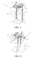
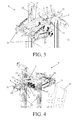
- FIG. 1 to 4 is an embodiment of the supply device according to the invention in perspective in the whole and shown in detail, from different angles.
- the supply device 1 (blank feeder) has a frame 3, with two parallel main profiles that are connected to each other via transverse profiles are.
- a swing arm to the frame 5 with one end attached, with which the other end is pivotably connected with a carrier.
- the carrier is formed by carrier arms, of which two bearing arms 7 adjacent a first end being hingedly connected with the swiveling arm and near the other, second end is pivotably connected to the first ends of two further support arms 9.
- the other, second ends of the supporting arms 9 are further connected via a first cylinder-piston combination 11 is connected to the swinging arm 5 and the second ends of the bearing arms 7 are connected via a second cylinder-piston combination 13 is connected to the frame 3.
- the pivot arm 5 is connected via a further cylinder-piston combination 15 is connected to the frame 3.
- Suction cups 17 and 19 are connected to the second ends of the support arms 7 and further supporting arms 9.
- the supply device further has a frame 3 connected with the pressure element 21, which during the moving of the suction cups against a plate held by the suction cups to the vacuum press and thereby breaks (see below for description of Figure 7 ).
- the pressure element 21 is located between the suction cups 17, which are connected with the carrying arms 7 on the one hand, and the suction cups 19 which are connected to the further support arms 9 on the other.
- the pressure element 21 is formed by a pressure roller which is displaceable against a spring force.
- the spring assembly is formed by two rods, or inner tubes which are telescopically slidable in two outer tubes. In the outer tubes or to the rods / pipes within can be a coil spring or the present inner and outer tubes can form gas springs.
- the frame 3 is attached to a carriage 23 that runs along a vertical guide 25 is displaceable. On the slide there are further transport wheels 27, for the further displacement of the plate to a plate holder 29, and a gripper 31 for gripping of a sheet present in the holder plate and the placement of the plate in a tray 33.
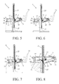
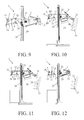
- FIGs 5 to 12 is the feeding of a plate 35 from the packing of a plate 35 of a stack 37 to the deposit of the plate in a tray 33 during various stages shown.
- the situation is shown wherein the upper plate 35 of the stack 37 is sucked by means of the suction cups 17 and 19. Then, the plate 35 of the stack is lifted, as shown in Figure 6 , and then in the direction of the plate holder 29 moves, as shown in Figure 7 .
- the plate 35 bears against the pressure element 21 is pulled so that the plate bends slightly and thereby disconnects the vacuum to the suction cups. Thereafter, the plate 35 by the transport wheels 27 to the holder plate 29 is transported. This is shown in Figure 8 .
- Figure 9 shows the situation in which the plate 35 in the plate holder 29 is present.
- the plate is then grasped by the gripper 31 and bottom parts of the plate holder 29 folded, as shown in Figure 10 .
- the plate 35 by the gripper 31 in the collecting tray 33 is placed.
- Figure 11 shows the situation in which the plate is released by the gripper correctly.
- Figure 12 shows the situation in which the supply device again back to the starting situation.
Landscapes
- Engineering & Computer Science (AREA)
- Mechanical Engineering (AREA)
- Sheets, Magazines, And Separation Thereof (AREA)
- Supplying Of Containers To The Packaging Station (AREA)
Applications Claiming Priority (1)
| Application Number | Priority Date | Filing Date | Title |
|---|---|---|---|
| NL2007699 | 2011-11-01 |
Publications (2)
| Publication Number | Publication Date |
|---|---|
| EP2653418A2 true EP2653418A2 (de) | 2013-10-23 |
| EP2653418A3 EP2653418A3 (de) | 2014-06-25 |
Family
ID=48876956
Family Applications (1)
| Application Number | Title | Priority Date | Filing Date |
|---|---|---|---|
| EP12190995.6A Withdrawn EP2653418A3 (de) | 2011-11-01 | 2012-11-01 | Plano-Blattzuführvorrichtung |
Country Status (2)
| Country | Link |
|---|---|
| EP (1) | EP2653418A3 (de) |
| NL (1) | NL2009022C2 (de) |
Family Cites Families (3)
| Publication number | Priority date | Publication date | Assignee | Title |
|---|---|---|---|---|
| US5716047A (en) * | 1994-03-31 | 1998-02-10 | Canon Kabushiki Kaisha | Recording or reading apparatus and sheet supply device with drive system having first and second mechanisms |
| JP2005127848A (ja) * | 2003-10-23 | 2005-05-19 | Meisei Electric Co Ltd | 標本封入機のカバーグラス移載装置 |
| US7604231B2 (en) * | 2007-01-30 | 2009-10-20 | Eastman Kodak Company | Method and apparatus for separating media combinations from a media stack |
-
2012
- 2012-06-18 NL NL2009022A patent/NL2009022C2/nl not_active IP Right Cessation
- 2012-11-01 EP EP12190995.6A patent/EP2653418A3/de not_active Withdrawn
Non-Patent Citations (1)
| Title |
|---|
| None |
Also Published As
| Publication number | Publication date |
|---|---|
| NL2009022C2 (nl) | 2013-05-07 |
| EP2653418A3 (de) | 2014-06-25 |
Similar Documents
| Publication | Publication Date | Title |
|---|---|---|
| EP3453655B1 (de) | Greifelement zum greifen einer schicht von produkten | |
| US4787810A (en) | Method and apparatus for handling stacks of loose sheet material | |
| CN108602633A (zh) | 夹持装置、卸垛系统、夹持方法和卸垛方法 | |
| ITUD20080049A1 (it) | Dispositivo alimentatore per barre e relativo procedimento di alimentazione | |
| US7690884B2 (en) | Finger and disk for separating plate-shaped objects, particularly battery plates | |
| CN107406206A (zh) | 用于重复地分离和移位袋子堆垛中最顶部袋子的设备和方法 | |
| CN204674931U (zh) | 一种包装袋折叠设备的送袋机构 | |
| EP2363280A1 (de) | Maschine und Verfahren zur Herstellung von Trayverpackungen | |
| EP2653418A2 (de) | Plano-Blattzuführvorrichtung | |
| US7381026B1 (en) | Mail traying apparatus | |
| CN210309191U (zh) | 一种用于纸箱包装的内衬成型入箱装置 | |
| CN209813204U (zh) | 一种新型的折盒设备 | |
| CN220640559U (zh) | 除膜设备和除膜系统 | |
| CN217836373U (zh) | 一种隔板转移装置及拆除外包装生产线 | |
| CN212667867U (zh) | 一种装书合盖设备 | |
| CN216468817U (zh) | 鞋子包纸设备 | |
| US10501221B2 (en) | Device and method for extraction | |
| AU2003203510B2 (en) | Method of Conveying Flat, Flexible Products and Apparatus for Implementing the Method | |
| CN209065173U (zh) | 一种铭板-纸分离装置 | |
| JP6974917B2 (ja) | 海苔供給装置 | |
| CN110142347B (zh) | 一种连续自动落料、堆垛、拆垛系统 | |
| CN110002033B (zh) | 手套夹取装置及夹取方法 | |
| EP2261146A3 (de) | Vorrichtung zum Behandeln von grossen Glasscheiben | |
| CN216035458U (zh) | 一种开箱机的开箱机构 | |
| CN115339895A (zh) | 一种产品外壳喷涂后下线自动装盘设备 |
Legal Events
| Date | Code | Title | Description |
|---|---|---|---|
| PUAI | Public reference made under article 153(3) epc to a published international application that has entered the european phase |
Free format text: ORIGINAL CODE: 0009012 |
|
| AK | Designated contracting states |
Kind code of ref document: A2 Designated state(s): AL AT BE BG CH CY CZ DE DK EE ES FI FR GB GR HR HU IE IS IT LI LT LU LV MC MK MT NL NO PL PT RO RS SE SI SK SM TR |
|
| AX | Request for extension of the european patent |
Extension state: BA ME |
|
| PUAL | Search report despatched |
Free format text: ORIGINAL CODE: 0009013 |
|
| AK | Designated contracting states |
Kind code of ref document: A3 Designated state(s): AL AT BE BG CH CY CZ DE DK EE ES FI FR GB GR HR HU IE IS IT LI LT LU LV MC MK MT NL NO PL PT RO RS SE SI SK SM TR |
|
| AX | Request for extension of the european patent |
Extension state: BA ME |
|
| RIC1 | Information provided on ipc code assigned before grant |
Ipc: B65H 3/54 20060101ALI20140519BHEP Ipc: B65H 3/08 20060101AFI20140519BHEP |
|
| STAA | Information on the status of an ep patent application or granted ep patent |
Free format text: STATUS: THE APPLICATION IS DEEMED TO BE WITHDRAWN |
|
| 18D | Application deemed to be withdrawn |
Effective date: 20150106 |