EP2653358A1 - Wheel washing machine - Google Patents
Wheel washing machine Download PDFInfo
- Publication number
- EP2653358A1 EP2653358A1 EP13002034.0A EP13002034A EP2653358A1 EP 2653358 A1 EP2653358 A1 EP 2653358A1 EP 13002034 A EP13002034 A EP 13002034A EP 2653358 A1 EP2653358 A1 EP 2653358A1
- Authority
- EP
- European Patent Office
- Prior art keywords
- drying
- machine
- washing
- fitted
- wheel
- Prior art date
- Legal status (The legal status is an assumption and is not a legal conclusion. Google has not performed a legal analysis and makes no representation as to the accuracy of the status listed.)
- Granted
Links
- 238000005406 washing Methods 0.000 title claims abstract description 63
- 238000001035 drying Methods 0.000 claims abstract description 80
- 239000007788 liquid Substances 0.000 claims abstract description 11
- 238000005507 spraying Methods 0.000 claims abstract description 7
- 239000012530 fluid Substances 0.000 claims description 7
- 238000007664 blowing Methods 0.000 claims description 6
- 238000010586 diagram Methods 0.000 description 8
- 238000011084 recovery Methods 0.000 description 4
- 239000007921 spray Substances 0.000 description 4
- XLYOFNOQVPJJNP-UHFFFAOYSA-N water Substances O XLYOFNOQVPJJNP-UHFFFAOYSA-N 0.000 description 4
- 238000004891 communication Methods 0.000 description 2
- 230000007423 decrease Effects 0.000 description 2
- 238000007605 air drying Methods 0.000 description 1
- 239000000956 alloy Substances 0.000 description 1
- 229910045601 alloy Inorganic materials 0.000 description 1
- 230000005540 biological transmission Effects 0.000 description 1
- 230000008878 coupling Effects 0.000 description 1
- 238000010168 coupling process Methods 0.000 description 1
- 238000005859 coupling reaction Methods 0.000 description 1
- 230000003247 decreasing effect Effects 0.000 description 1
- 238000006073 displacement reaction Methods 0.000 description 1
- 230000000694 effects Effects 0.000 description 1
- 230000005484 gravity Effects 0.000 description 1
- 239000000463 material Substances 0.000 description 1
- 239000000203 mixture Substances 0.000 description 1
- 230000002093 peripheral effect Effects 0.000 description 1
Images


Classifications
-
- B—PERFORMING OPERATIONS; TRANSPORTING
- B60—VEHICLES IN GENERAL
- B60S—SERVICING, CLEANING, REPAIRING, SUPPORTING, LIFTING, OR MANOEUVRING OF VEHICLES, NOT OTHERWISE PROVIDED FOR
- B60S3/00—Vehicle cleaning apparatus not integral with vehicles
- B60S3/002—Vehicle drying apparatus
-
- B—PERFORMING OPERATIONS; TRANSPORTING
- B60—VEHICLES IN GENERAL
- B60S—SERVICING, CLEANING, REPAIRING, SUPPORTING, LIFTING, OR MANOEUVRING OF VEHICLES, NOT OTHERWISE PROVIDED FOR
- B60S3/00—Vehicle cleaning apparatus not integral with vehicles
- B60S3/04—Vehicle cleaning apparatus not integral with vehicles for exteriors of land vehicles
- B60S3/042—Wheel cleaning devices
Definitions
- the invention relates to a wheel washing machine, which is generally designed for automatically washing and drying vehicle wheels.
- a prior art wheel washing machine is composed of a box-like frame, having a recovery tank at the bottom, and a washing chamber defined thereabove, for receiving a wheel to be washed in a vertical position.
- the bottom of the washing chamber communicates with the underlying recovery tank.
- Two transverse, parallel and horizontal support rollers are mounted in the washing chamber, close to the bottom thereof, and above the recovery tank, one of such rollers being rotatably supported as a powered roller, and the other being supported as an idler roller, said rollers being designed to provide support to a wheel to be washed, which is disposed with its center axis substantially parallel to the two rollers.
- the powered roller drives the wheel to be washed into rotation by adhesion with the tire tread, and causes it to rotate substantially about its center axis.
- Spray nozzles are mounted to special support flanges at each side, i.e. close to the side walls that delimit the washing chamber, said nozzles being used to spray pressurized washing liquids and being adapted to be oriented toward the wheel.
- blow nozzles are also provided, for blowing compressed air or another pressurized fluid to dry the wheels, and also adapted to be oriented toward the wheels at predetermined angles of incidence to the two side surfaces of the wheel.
- Retaining rollers are also provided in the washing chamber close to its side walls, said rollers being idly mounted, with axes of rotation substantially perpendicular to the wheel axis, their outer surfaces allowing the wheel to be held in a substantially vertical position as it rotates during the washing and drying steps, and preventing it from tilting and hitting the walls of the washing chamber, especially at the start or the end of its rotation, i.e. when it has a poor balance due to the lower polar moment about the axis of rotation.
- the washing chamber has a substantially parallelepiped shape and is peripherally closed at the sides and top.
- a front door is provided for access and introduction or removal of wheels.
- the washing chamber has apertures for communication with the underlying tank which collects the washing liquid pouring down from the wheel as well as the dirt residues removed from its surfaces.
- the frame of the wheel washing machine also has an appendage, or additional part, which is typically located at the side of the recovery tank and the washing chamber, in which all the devices that cooperate to the operation of the machine are received and protected.
- the wheel While the washing liquid is being sprayed, the wheel is driven into rotation such that, as it rotates, every part of it repeatedly passes before the spraying nozzles, which are oriented beforehand such that their jets impinge upon the wheel surfaces at predetermined angles of incidence, to obtain a higher impact force and hence a better washing effect.
- the drying nozzles are operated, such nozzles being also located at each side of the wheel with such an orientation as to hit the surfaces with air jets at predetermined angles, for the residual washing water to be pushed away from the wheel surfaces, i.e. the rim and tire surfaces.
- this prior art has the drawback that, during drying, the compressed air jets that are simultaneously blown from the two opposed sides of the washing chamber toward the two corresponding vertical faces of the wheel, especially the surfaces of the rim disk and the intrados of its channel, tend to generate deflected and disturbed flows, due to the substantially opposite directions in which they flow toward each other.
- One object of the invention is to improve the prior art.
- a further object of the invention is to obviate the above drawback, by providing a wheel washing machine that affords quick and thorough drying of wheels.
- Yet another object of the invention is to provide a wheel washing machine that requires no particular structural change to improve drying of washed wheels.
- the invention relates to a wheel washing machine as defined in the features of claim 1.
- numeral 1 generally designates a machine for automatically washing and drying wheels 3, hereinafter briefly referred to as machine 1.
- the machine 1 comprises a frame with a base 2 having a tank (not shown) defined therein, in which the liquid that is used for washing wheels 3, typically vehicle wheels, is collected.
- the base 2 has a box-like structure 4 fixed above it, which forms an inner chamber 5 and is closed at three peripheral sides and at the top, whereas the front wall is open and adapted to be closed by a panel 6 that is hinged at the base of the side walls 7 and 8 of the structure 4.
- the bottom of the chamber 5 is also normally open, to allow the washing liquid to spontaneously pour by gravity into the lower collection tank.
- the members for operating the machine 1, namely a pump unit 10 and a motor unit 11, are mounted beside the structure 4, on the base 2.
- Two transverse, parallel and horizontal rollers 12 and 14 are mounted in the chamber 5 that is designed to receive a wheel 3 to be washed and dried, namely in its lower portion, one of such rollers, namely the roller 12 being freely rotatable, whereas the roller 13 is mechanically connected to a coupling 14 for connection to the motor unit 11.
- rollers 12 and 13 provide support to the wheels 3 to be washed and dried, that are arranged in a substantially vertical position, with their center axis of rotation "A" substantially parallel to the two rollers 12 and 13.
- Sets of additional rollers 15 are mounted to the side walls 7 and 8 by brackets 16, such rollers being freely rotatable and having the special function of holding the wheels 3 in a vertical or substantially vertical position, as they are being washed and dried, as better explained below.
- Spraying and drying units are also mounted to the side walls 7 and 8, and emit jets of a washing liquid or compressed air drying flows toward the opposed faces of a wheel 3, as shown in Figures 2 and 3 , and generally referenced 19 and 20.
- Figure 3 the technical problem that is solved by the invention is shown in Figure 3 : as a wheel 3 is being dried, the directions of the compressed air flows 19 and 20, which have predetermined angles of incidence to the opposite faces of a wheel 3, typically generate components perpendicular to the faces of the wheel 3, which oppose to each other, as shown by arrows T1 and T2, thereby reducing drying effectiveness, and hindering normal pouring of the washing liquid from the surfaces of the faces of the wheel 3, particularly the inner surfaces 22 of the rim C.
- Figures 4 , 5 , 6 show a first embodiment of a pneumatic diagram of a system for actuating the drying units 113 and 213, which are part of the above mentioned units 17 and 18.
- numeral 113 designates a first drying unit and 213 designates a second drying unit, each comprising a plurality of ejecting nozzles 23 and 24, which are fed by respective pipes, namely a first pipe 143 and a second pipe 43.
- Both the first and second pipes 143 and 43 have first and second distribution valves 137 and 37 respectively, of the type having two operating positions P1 and P2.
- the position P1 is an open fluid flow position, whereas the position P2 is a closed fluid flow position.
- the first and second distribution valves are normally kept in the closed position by elastic means 41 and 141, which are preloaded with an adequate bias force acting upon the spools 40 and 140 of the two valves 37 and 137 respectively.
- the distribution valves 137 and 37 are reached by a first pipe 136 and a second pipe 36 respectively, which carry compressed air from a common source 35.
- An electronic control unit for controlling the operation of the machine 1 is generally referenced 44 and is connected via connecting lines 45 and 145 to the two spools 40 and 140, to actuate them upon request and switch the positions P1 and P2 of the distribution valves 37 and 137.
- numerals 38 and 138 designate the fluid inlet ports in the distribution valves 37 and 137
- numerals 39 and 139 designate the corresponding outlet ports to the two drying units 113 and 213.
- a single pipe 36 is shown to extend from the compressed air source 35, and to end in a port 238 of a distribution valve 237 which has three operating positions in this embodiment, i.e. P3, P4, P5.
- the two positions P4 and P5 are open positions, allowing the compressed air flows to alternately reach the first drying unit 213 or the second drying unit 113, whereas the central position P3 is a closed position in which the passage of complex air is completely prevented.
- the electronic unit for controlling the operation of the machine 1 is referenced 44 also in this embodiment.
- the electronic control unit 44 is connected via connection lines 45 and 145 to the ends 40 and 140 of the spool, which controls the positions of the distribution valve 237 to actuate displacement thereof as required.
- the distribution valve 237 is normally kept in the closed position P3 by means of opposite bias forces provided by the two preloaded elastic elements 41 and 141.
- numeral 238 designates an inlet port of the valve 237
- numerals 239 and 339 designate the outlet ports to the first drying unit 213 and the second drying unit 113 respectively.
- the compressed air source 35 is shown to be connected, by a pipe 36 connected to an inlet port 338, to a first distribution valve 37 having two operating positions, namely an open position P1 and a closed position P2, said valve being normally kept in the closed position P2 by means of a preloaded elastic element 141, which pushes the spool 40 of the valve 37.
- the latter is in turn connected to a second distribution valve 437, also having two operating positions designated as P6 and P7, and normally kept in the operating position P6 by a second preloaded elastic element 541, by a further pipe that has one end connected to an outlet port 439 of the first valve 37 and an opposite end connected to an inlet port 438 of the second distribution valve 437, which has two outlet ports 539 and 639 respectively.
- the outlet port 539 is connected to the first drying unit 213 by a pipe 43 whereas the outlet port 639 is connected to the second drying unit 113 by a further pipe 143.
- the two operating positions P6 and P7 allow alternate communication of the inlet port 438 with one of the outlet ports 538 or 639.
- an electronic control unit 44 is provided, which is connected to the spools 40 and 540 of the two valves 37 and 437 by means of respective connection lines 45 and 145 to actuate the movements of the two spools and switch the operating positions P1 or P2 and P6 or P7.
- the electronic control unit 44 sends a first signal to the spool of the distribution valve 37, thereby causing it to switch to the open position P1, whereas the distribution valve 137 remains in the closed position P2.
- the wheel 3 to be dried receives the compressed air flow on one face for as long as is required for full removal of the washing water and drying.
- the latter sends an actuation pulse to the spool 140 of the distribution valve 137, which switches to the open position P1 and simultaneously stops the actuation pulse to the spool 40 of the distribution valve 37, which switches back to the closed position P2 under the bias of the elastic element 41 that was previously compressed in the open position.
- valves 37 and 137 are replaced by a single distribution valve 237 having three operating positions.
- valve 237 is in the closed configuration P3 and none of the two drying units 113 and 213 is fed with the compressed air generated by the source 35.
- the electronic control unit 44 sends an actuation pulse through the line 45, e.g. to the end 40 of the spool of the distribution valve 237, which switches to the position P4 as shown in Figure 8 , thereby compressing the elastic element 141, whereby the pipe 36 is connected to the pipe 43 and hence with the first drying unit 213 which eject the compressed air flow toward a first face of the wheel 3: this configuration is shown in Figure 8 .
- the latter sends an actuation pulse to the opposite end 140 of the spool of the distribution valve 237 and simultaneously stops the previous pulse to the end 40.
- the distribution valve 237 switches to the operating position P5 and the compressed air reaches the second drying unit 113, as shown in Figure 9 , such unit ejecting the flow of drying compressed air toward the face of the wheel 3 to be dried opposite to the previous face, for a second drying time, as preset in the electronic control unit 44.
- the electronic control unit 44 stops pulse transmission, and the elastic elements 41 and 141 restore the valve 237 to the normally closed position P3.
- the source 35 sends air through the pipe 36 to the inlet port 338 of the first distribution valve 37, which is kept in the closed position P2.
- the electronic control unit 44 sends a pulse to the first distribution valve 37 through the line 45 and switches it to the open position P1: this configuration is shown in Figure 11 .
- compressed air flows into the inlet port 338, flows out of the outlet port 439, flows into the inlet port 438 of the second distribution valve 437 and flows out of the outlet port 539, thereby reaching the first drying unit 213 which ejects drying air flows toward one of the faces of the wheel 3 to be dried.
- the electronic control unit 44 sends a switching signal to the second distribution valve 437 which switches to the position P6, preceding the position P7: this configuration is shown in Figure 12 .
- the compressed air that flows through the first distribution valve 37 reaches the inlet port 438 of the second distribution valve 437, flows out of the outlet port 639 thereof, and feeds the second drying unit 113 which ejects compressed air flows toward the face of the wheel 3 to be dried opposite to the previous face.
- the electronic control unit 44 stops the signals to both the first distribution valve 37 and the second distribution valve 437, which valves are biased by the action of their respective elastic return elements, and are automatically restored to their respective normal positions, i.e. the closed position P2 for the valve 37 and the distribution position P6 to the first drying unit 213.
- the first distribution valve 37 acts as an ON/OFF switch
- the second distribution valve 437 acts as a compressed air flow deflector, deflecting flows toward the first drying unit 213 or toward the second drying unit 113.
- the latter are emitted alternately by the drying units 113 and 213 do not oppose each other, with the surfaces of the wheels 3 being cleared of washing liquid residues in shorter times.
- drying cycles are repeated twice for each face of each wheel 3, to remove the residual water that may have flown to the opposite surface during a first drying cycle, and vice versa.
- drying times may be set for the two faces of each wheel 3, to account for the different areas of the surfaces to be dried, and typically to provide longer cycles for the inner surfaces 22 of the rim "C".
- the invention was found to fulfill the intended objects.
Abstract
Description
- The invention relates to a wheel washing machine, which is generally designed for automatically washing and drying vehicle wheels.
- Machines for washing vehicle wheels and drying them after the washing cycle have been long known.
- Typically, a prior art wheel washing machine is composed of a box-like frame, having a recovery tank at the bottom, and a washing chamber defined thereabove, for receiving a wheel to be washed in a vertical position.
- The bottom of the washing chamber communicates with the underlying recovery tank.
- Two transverse, parallel and horizontal support rollers are mounted in the washing chamber, close to the bottom thereof, and above the recovery tank, one of such rollers being rotatably supported as a powered roller, and the other being supported as an idler roller, said rollers being designed to provide support to a wheel to be washed, which is disposed with its center axis substantially parallel to the two rollers.
- As the motor unit that is connected to the powered roller is actuated by an operator, the powered roller drives the wheel to be washed into rotation by adhesion with the tire tread, and causes it to rotate substantially about its center axis.
- Spray nozzles are mounted to special support flanges at each side, i.e. close to the side walls that delimit the washing chamber, said nozzles being used to spray pressurized washing liquids and being adapted to be oriented toward the wheel.
- In addition to these spray nozzles, blow nozzles are also provided, for blowing compressed air or another pressurized fluid to dry the wheels, and also adapted to be oriented toward the wheels at predetermined angles of incidence to the two side surfaces of the wheel.
- Retaining rollers are also provided in the washing chamber close to its side walls, said rollers being idly mounted, with axes of rotation substantially perpendicular to the wheel axis, their outer surfaces allowing the wheel to be held in a substantially vertical position as it rotates during the washing and drying steps, and preventing it from tilting and hitting the walls of the washing chamber, especially at the start or the end of its rotation, i.e. when it has a poor balance due to the lower polar moment about the axis of rotation.
- The washing chamber has a substantially parallelepiped shape and is peripherally closed at the sides and top.
- A front door is provided for access and introduction or removal of wheels.
- At the bottom, as mentioned above, the washing chamber has apertures for communication with the underlying tank which collects the washing liquid pouring down from the wheel as well as the dirt residues removed from its surfaces.
- The frame of the wheel washing machine also has an appendage, or additional part, which is typically located at the side of the recovery tank and the washing chamber, in which all the devices that cooperate to the operation of the machine are received and protected.
- During washing, a pressurized water and cleanser mixture accumulated in a reservoir specially designed therefor in the frame and connected by pipes to the spray nozzles, is sprayed by the action of a pump to the two faces of a wheel disposed in a vertical position in the washing chamber, with the tire tread on the two transverse support rollers.
- While the washing liquid is being sprayed, the wheel is driven into rotation such that, as it rotates, every part of it repeatedly passes before the spraying nozzles, which are oriented beforehand such that their jets impinge upon the wheel surfaces at predetermined angles of incidence, to obtain a higher impact force and hence a better washing effect.
- Likewise, once the washing step has been completed, the drying nozzles are operated, such nozzles being also located at each side of the wheel with such an orientation as to hit the surfaces with air jets at predetermined angles, for the residual washing water to be pushed away from the wheel surfaces, i.e. the rim and tire surfaces.
- Nevertheless, this prior art has the drawback that, during drying, the compressed air jets that are simultaneously blown from the two opposed sides of the washing chamber toward the two corresponding vertical faces of the wheel, especially the surfaces of the rim disk and the intrados of its channel, tend to generate deflected and disturbed flows, due to the substantially opposite directions in which they flow toward each other.
- These deflections considerably decrease the drying effectiveness, because air jets lose their force as they divide into directional components both perpendicular and tangent to the surfaces to be hit, such decreased effectiveness being reflected in undesirably longer times to complete this step, which both requires a higher power consumption and decreases the number of wheels that can be washed and dried in a predetermined time, e.g. a working day.
- This occurs because the perpendicular components of air jets flow through the holes of the rims, or through the spikes (in case of special rims or alloy rims), as the wheel rotates, to the opposite side thereof, and interfere with the directly opposed air jets.
- One object of the invention is to improve the prior art.
- A further object of the invention is to obviate the above drawback, by providing a wheel washing machine that affords quick and thorough drying of wheels.
- Yet another object of the invention is to provide a wheel washing machine that requires no particular structural change to improve drying of washed wheels.
- In one aspect the invention relates to a wheel washing machine as defined in the features of
claim 1. - The invention affords the following advantages:
- generally improved drying of the washed wheels; and
- reduced drying times.
- Further characteristics and advantages of the invention will be more apparent upon reading of the detailed description of one preferred, non-exclusive embodiment of a wheel washing machine of the invention, which is illustrated by way of example and without limitation in the annexed drawings, in which:
-
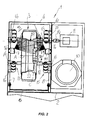
FIG. 1 is a general perspective view of a wheel washing machine of the invention; -
FIG. 2 is a schematic top view of the wheel washing machine ofFigure 1 ; -
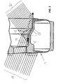
FIG. 3 is a detail view of a lower portion of a wheel as it is being dried by simultaneous jets of drying fluid, according to the prior art; -
FIG. 4 is a view of a pneumatic diagram of a first possible embodiment of a system for actuating the drying units of the wheel washing machine of the invention, in a configuration in which drying is stopped; -
FIG. 5 is a view of the diagram ofFigure 4 , in a configuration in which a first drying unit is actuated; -
FIG. 6 is a view of the diagram ofFigure 4 , in a configuration in which a second drying unit is actuated; -
FIG. 7 is a view of a second possible embodiment of a system for actuating the drying units of the wheel washing machine of the invention, in a configuration in which drying is stopped; -
FIG. 8 is a view of the diagram ofFigure 7 , in a configuration in which a first drying unit is actuated; -
FIG. 9 is a view of the diagram ofFigure 7 , in a configuration in which a second drying unit is actuated; -
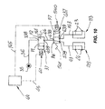
FIG. 10 is a view of a third possible embodiment of a system for actuating the drying units of the wheel washing machine of the invention, in a configuration in which drying is stopped; -
FIG. 11 is a view of the diagram ofFigure 10 , in a configuration in which a first drying unit is actuated; -
FIG. 12 is a view of the diagram ofFigure 10 , in a configuration in which a second drying unit is actuated. - Referring to
Figure 1 ,numeral 1 generally designates a machine for automatically washing and dryingwheels 3, hereinafter briefly referred to asmachine 1. - More in detail, the
machine 1 comprises a frame with abase 2 having a tank (not shown) defined therein, in which the liquid that is used forwashing wheels 3, typically vehicle wheels, is collected. - The
base 2 has a box-like structure 4 fixed above it, which forms aninner chamber 5 and is closed at three peripheral sides and at the top, whereas the front wall is open and adapted to be closed by apanel 6 that is hinged at the base of theside walls structure 4. - The bottom of the
chamber 5 is also normally open, to allow the washing liquid to spontaneously pour by gravity into the lower collection tank. - The members for operating the
machine 1, namely apump unit 10 and amotor unit 11, are mounted beside thestructure 4, on thebase 2. - Two transverse, parallel and
horizontal rollers chamber 5 that is designed to receive awheel 3 to be washed and dried, namely in its lower portion, one of such rollers, namely theroller 12 being freely rotatable, whereas theroller 13 is mechanically connected to acoupling 14 for connection to themotor unit 11. - These
rollers wheels 3 to be washed and dried, that are arranged in a substantially vertical position, with their center axis of rotation "A" substantially parallel to the tworollers - Sets of
additional rollers 15 are mounted to theside walls brackets 16, such rollers being freely rotatable and having the special function of holding thewheels 3 in a vertical or substantially vertical position, as they are being washed and dried, as better explained below. - Spraying and drying units, generally referenced 17 and 18, are also mounted to the
side walls wheel 3, as shown inFigures 2 and3 , and generally referenced 19 and 20. - More in detail, the technical problem that is solved by the invention is shown in
Figure 3 : as awheel 3 is being dried, the directions of the compressed air flows 19 and 20, which have predetermined angles of incidence to the opposite faces of awheel 3, typically generate components perpendicular to the faces of thewheel 3, which oppose to each other, as shown by arrows T1 and T2, thereby reducing drying effectiveness, and hindering normal pouring of the washing liquid from the surfaces of the faces of thewheel 3, particularly theinner surfaces 22 of the rim C. -
Figures 4 ,5 ,6 show a first embodiment of a pneumatic diagram of a system for actuating thedrying units units - More in detail,
numeral 113 designates a first drying unit and 213 designates a second drying unit, each comprising a plurality of ejectingnozzles first pipe 143 and asecond pipe 43. - Both the first and
second pipes second distribution valves - As shown in the figures, the position P1 is an open fluid flow position, whereas the position P2 is a closed fluid flow position.
- The first and second distribution valves are normally kept in the closed position by
elastic means spools valves - As shown in the figures, the
distribution valves first pipe 136 and asecond pipe 36 respectively, which carry compressed air from acommon source 35. - An electronic control unit for controlling the operation of the
machine 1 is generally referenced 44 and is connected via connectinglines spools distribution valves - In the figures,
numerals distribution valves numerals drying units - Referring to
Figures 7 ,8 ,9 , in which like reference numerals designate like elements ofFigures 4 ,5 ,6 , asingle pipe 36 is shown to extend from thecompressed air source 35, and to end in aport 238 of adistribution valve 237 which has three operating positions in this embodiment, i.e. P3, P4, P5. - More in detail, the two positions P4 and P5 are open positions, allowing the compressed air flows to alternately reach the
first drying unit 213 or thesecond drying unit 113, whereas the central position P3 is a closed position in which the passage of complex air is completely prevented. - The electronic unit for controlling the operation of the
machine 1 is referenced 44 also in this embodiment. - The
electronic control unit 44 is connected viaconnection lines ends distribution valve 237 to actuate displacement thereof as required. - As shown in the Figures, the
distribution valve 237 is normally kept in the closed position P3 by means of opposite bias forces provided by the two preloadedelastic elements - In
Figures 7 ,8 ,9 , numeral 238 designates an inlet port of thevalve 237, whereasnumerals first drying unit 213 and thesecond drying unit 113 respectively. - Referring to
Figures 10 ,11 ,12 , in which like reference numerals designate like elements ofFigures 4 ,5 ,6 , thecompressed air source 35 is shown to be connected, by apipe 36 connected to aninlet port 338, to afirst distribution valve 37 having two operating positions, namely an open position P1 and a closed position P2, said valve being normally kept in the closed position P2 by means of a preloadedelastic element 141, which pushes thespool 40 of thevalve 37. - The latter is in turn connected to a
second distribution valve 437, also having two operating positions designated as P6 and P7, and normally kept in the operating position P6 by a second preloadedelastic element 541, by a further pipe that has one end connected to anoutlet port 439 of thefirst valve 37 and an opposite end connected to aninlet port 438 of thesecond distribution valve 437, which has twooutlet ports - The
outlet port 539 is connected to thefirst drying unit 213 by apipe 43 whereas theoutlet port 639 is connected to thesecond drying unit 113 by afurther pipe 143. - Referring to the
second distribution valve 437, it shall be noted that the two operating positions P6 and P7 allow alternate communication of theinlet port 438 with one of theoutlet ports 538 or 639. - Like in the previous embodiments, an
electronic control unit 44 is provided, which is connected to thespools valves respective connection lines - The operation of the invention will be now described in detail for each of the above embodiments.
- In detail, referring to the first embodiment as shown in
Figures 4 ,5 ,6 , in the configuration as shown inFigure 4 the two dryingunits source 35 and reaches the twodistribution valves - When the
machine 1 has completed a washing cycle on awheel 3, theelectronic control unit 44 sends a first signal to the spool of thedistribution valve 37, thereby causing it to switch to the open position P1, whereas thedistribution valve 137 remains in the closed position P2. - In this configuration, which is shown in
Figure 5 , only thefirst drying unit 213 is fed with compressed air, whereas thesecond unit 113 is idle. - Thus, the
wheel 3 to be dried receives the compressed air flow on one face for as long as is required for full removal of the washing water and drying. - At the end of a first drying time, as preset in the
electronic control unit 44, the latter sends an actuation pulse to thespool 140 of thedistribution valve 137, which switches to the open position P1 and simultaneously stops the actuation pulse to thespool 40 of thedistribution valve 37, which switches back to the closed position P2 under the bias of theelastic element 41 that was previously compressed in the open position. - In this configuration, as shown in
Figure 6 , only thesecond drying unit 113 is fed with compressed air, whereas the first unit is idle and thewheel 3 to be dried receives a compressed air flow on the face opposite to the previous face, for a second drying time, as preset in theelectronic control unit 44. - The operation of the second embodiment as shown in
Figures 7 ,8 ,9 allows alternate and automatic actuation of the two dryingunits - The difference from the above described embodiment is that the two
valves single distribution valve 237 having three operating positions. - As shown in
Figure 7 , thevalve 237 is in the closed configuration P3 and none of the two dryingunits source 35. - When the washing cycle on the
wheel 3 is completed, theelectronic control unit 44 sends an actuation pulse through theline 45, e.g. to theend 40 of the spool of thedistribution valve 237, which switches to the position P4 as shown inFigure 8 , thereby compressing theelastic element 141, whereby thepipe 36 is connected to thepipe 43 and hence with thefirst drying unit 213 which eject the compressed air flow toward a first face of the wheel 3: this configuration is shown inFigure 8 . - At the end of the first drying time, as preset in the
electronic control unit 44, the latter, like in the previous case, sends an actuation pulse to theopposite end 140 of the spool of thedistribution valve 237 and simultaneously stops the previous pulse to theend 40. - Therefore, the
distribution valve 237 switches to the operating position P5 and the compressed air reaches thesecond drying unit 113, as shown inFigure 9 , such unit ejecting the flow of drying compressed air toward the face of thewheel 3 to be dried opposite to the previous face, for a second drying time, as preset in theelectronic control unit 44. - As soon as the drying step is completed, the
electronic control unit 44 stops pulse transmission, and theelastic elements valve 237 to the normally closed position P3. - Referring to
Figures 10 ,11 ,12 , compressed air delivery is shown, particularly inFigure 10 , to be blocked. - The
source 35 sends air through thepipe 36 to theinlet port 338 of thefirst distribution valve 37, which is kept in the closed position P2. - Therefore, in this configuration, i.e. the configuration that is maintained while
wheels 3 are being washed, compressed air reaches none of the dryingunits - As soon as the washing step is completed, the
electronic control unit 44 sends a pulse to thefirst distribution valve 37 through theline 45 and switches it to the open position P1: this configuration is shown inFigure 11 . - In this configuration, compressed air flows into the
inlet port 338, flows out of theoutlet port 439, flows into theinlet port 438 of thesecond distribution valve 437 and flows out of theoutlet port 539, thereby reaching thefirst drying unit 213 which ejects drying air flows toward one of the faces of thewheel 3 to be dried. - As soon as the predetermined time of actuation of the
first drying unit 213 is completed, theelectronic control unit 44 sends a switching signal to thesecond distribution valve 437 which switches to the position P6, preceding the position P7: this configuration is shown inFigure 12 . - In this configuration, the compressed air that flows through the
first distribution valve 37 reaches theinlet port 438 of thesecond distribution valve 437, flows out of theoutlet port 639 thereof, and feeds thesecond drying unit 113 which ejects compressed air flows toward the face of thewheel 3 to be dried opposite to the previous face. - When the predetermined time of actuation of the
second drying unit 113 is also completed, theelectronic control unit 44 stops the signals to both thefirst distribution valve 37 and thesecond distribution valve 437, which valves are biased by the action of their respective elastic return elements, and are automatically restored to their respective normal positions, i.e. the closed position P2 for thevalve 37 and the distribution position P6 to thefirst drying unit 213. - In other words, the
first distribution valve 37 acts as an ON/OFF switch, whereas thesecond distribution valve 437 acts as a compressed air flow deflector, deflecting flows toward thefirst drying unit 213 or toward thesecond drying unit 113. - It shall be noted that, during washing and drying of the
wheels 3, the latter are driven into rotation on therollers chamber 5, which is kept closed at the top and the periphery, such that all the parts of the surfaces of the opposite faces of thewheels 3 may pass before the spraying and dryingunits - The latter are emitted alternately by the drying
units wheels 3 being cleared of washing liquid residues in shorter times. - Furthermore, the drying cycles are repeated twice for each face of each
wheel 3, to remove the residual water that may have flown to the opposite surface during a first drying cycle, and vice versa. - Finally, different drying times may be set for the two faces of each
wheel 3, to account for the different areas of the surfaces to be dried, and typically to provide longer cycles for theinner surfaces 22 of the rim "C". - The invention was found to fulfill the intended objects.
- The invention so conceived is susceptible to a number of changes and variants within the inventive concept.
- Furthermore, all the details may be replaced by other technically equivalent parts.
- In practical implementation, any materials, shapes and sizes may be used as needed, without departure from the scope of the following claims.
Claims (8)
- A tyre washing machine (1) comprising:- A frame that shapes a washing station (4) wherein wheels (3) to be washed are designed to be fitted;- A first spraying set (17) of a washing liquid fitted on a first side of said washing station (4) and a second spraying set (18) fitted on a second opposite side of said washing station (4); and- A first drying set (213) fitted on said first side of said washing station (4) and a second drying set (113) fitted on said second opposite side of said washing station (4);
characterized in that said first drying set (213) and said second drying set (113) can be alternatively actuated by alternative actuating means (44, 35, 37, 137), so as to work with alternated drying cycles. - A machine as claimed in claim 1, wherein said first and second drying set comprise:- A source (35) of a pressurized drying fluid;- Flowing lines (36, 136) of said fluid from said source (35) toward first blowing devices (213) and second blowing devices (113) arranged in said washing station (4), facing a respective face of a wheel (3) do be dried;- Control means (37, 137) of said flowing lines (36, 136) designed to selectively connect said source (35) to said first or second blowing devices (213, 113).
- A machine as claimed in claim 1 or 2, wherein said flowing lines comprise:- A first connecting duct (143) connecting said source (35) to said first blowing devices (213);- A second connecting duct (43) connecting said source (35) to said second blowing devices (113).
- A machine as claimed in anyone of preceding claims, wherein said control means comprise:- A first valve (137) having at least two switchable working positions (P1, P2) comprising a first connecting position (P1) and a second closing position (P2), fitted on said first duct (143);- A second valve (37) having at least two switchable working positions (P1, P2) comprising a first connecting position (P1) and a second closing position (P2), fitted on said second duct (43);- A programmable electronic switching unit (44) of said first valve (137) and second valve (37).
- A machine as claimed in anyone of preceding claims, wherein said first and second valve (137, 37) are normally forced in said closing positions (P2) by forcing elastic means (41, 141).
- A machine as claimed in claim 1, wherein said first and second drying devices (213, 113) each comprises a first and a second manifold body wherein ends of said first duct (143) and second duct (43) respectively flow and equipped with a plurality of turnable ejecting nozzles (23, 24).
- A machine as claimed in claim 1, wherein said alternate drying cycles have.the same duration.
- A machine as claimed in claim 1, wherein said alternate drying cycles have different duration.
Priority Applications (1)
| Application Number | Priority Date | Filing Date | Title |
|---|---|---|---|
| PL13002034T PL2653358T3 (en) | 2012-04-19 | 2013-04-18 | Wheel washing machine |
Applications Claiming Priority (1)
| Application Number | Priority Date | Filing Date | Title |
|---|---|---|---|
| IT000103A ITMO20120103A1 (en) | 2012-04-19 | 2012-04-19 | WHEEL WASHING MACHINE |
Publications (2)
| Publication Number | Publication Date |
|---|---|
| EP2653358A1 true EP2653358A1 (en) | 2013-10-23 |
| EP2653358B1 EP2653358B1 (en) | 2015-01-14 |
Family
ID=46124646
Family Applications (1)
| Application Number | Title | Priority Date | Filing Date |
|---|---|---|---|
| EP13002034.0A Active EP2653358B1 (en) | 2012-04-19 | 2013-04-18 | Wheel washing machine |
Country Status (4)
| Country | Link |
|---|---|
| EP (1) | EP2653358B1 (en) |
| IT (1) | ITMO20120103A1 (en) |
| PL (1) | PL2653358T3 (en) |
| RU (1) | RU2621526C2 (en) |
Cited By (2)
| Publication number | Priority date | Publication date | Assignee | Title |
|---|---|---|---|---|
| WO2015071505A1 (en) * | 2013-11-12 | 2015-05-21 | Ibasan S.A. | Machine for automatically washing vehicle wheels |
| CN108128284A (en) * | 2017-12-21 | 2018-06-08 | 宁波高新区新柯保汽车科技有限公司 | Stone remove device in tire |
Citations (5)
| Publication number | Priority date | Publication date | Assignee | Title |
|---|---|---|---|---|
| EP0338509A1 (en) * | 1988-04-22 | 1989-10-25 | STERN, Leif Einar | Device for cleaning vehicle wheels |
| WO1990011210A1 (en) * | 1989-03-20 | 1990-10-04 | Eino Hakala | Apparatus for washing a vehicle tyre |
| DE20110008U1 (en) * | 2001-06-16 | 2001-08-30 | Stadler Johann | Washing or cleaning device for vehicle tires or vehicle wheels |
| WO2005120913A2 (en) * | 2004-06-07 | 2005-12-22 | Arne Hjorth Hansen | Device for washing vehicle wheels |
| DE102005009876A1 (en) * | 2005-03-01 | 2006-09-07 | Gerhard Paulus | Compact universal size washing system for vehicle wheels which are held in a tilted position by support rollers and support slides |
Family Cites Families (2)
| Publication number | Priority date | Publication date | Assignee | Title |
|---|---|---|---|---|
| RU2213019C2 (en) * | 2002-01-03 | 2003-09-27 | Козьев Евгений Васильевич | Vehicle wheel washer |
| RU2246413C2 (en) * | 2002-11-28 | 2005-02-20 | Закрытое акционерное общество "Экологический промышленно-финансовый концерн "Мойдодыр" | Wheel washer |
-
2012
- 2012-04-19 IT IT000103A patent/ITMO20120103A1/en unknown
-
2013
- 2013-04-17 RU RU2013117695A patent/RU2621526C2/en active
- 2013-04-18 EP EP13002034.0A patent/EP2653358B1/en active Active
- 2013-04-18 PL PL13002034T patent/PL2653358T3/en unknown
Patent Citations (5)
| Publication number | Priority date | Publication date | Assignee | Title |
|---|---|---|---|---|
| EP0338509A1 (en) * | 1988-04-22 | 1989-10-25 | STERN, Leif Einar | Device for cleaning vehicle wheels |
| WO1990011210A1 (en) * | 1989-03-20 | 1990-10-04 | Eino Hakala | Apparatus for washing a vehicle tyre |
| DE20110008U1 (en) * | 2001-06-16 | 2001-08-30 | Stadler Johann | Washing or cleaning device for vehicle tires or vehicle wheels |
| WO2005120913A2 (en) * | 2004-06-07 | 2005-12-22 | Arne Hjorth Hansen | Device for washing vehicle wheels |
| DE102005009876A1 (en) * | 2005-03-01 | 2006-09-07 | Gerhard Paulus | Compact universal size washing system for vehicle wheels which are held in a tilted position by support rollers and support slides |
Cited By (3)
| Publication number | Priority date | Publication date | Assignee | Title |
|---|---|---|---|---|
| WO2015071505A1 (en) * | 2013-11-12 | 2015-05-21 | Ibasan S.A. | Machine for automatically washing vehicle wheels |
| CN108128284A (en) * | 2017-12-21 | 2018-06-08 | 宁波高新区新柯保汽车科技有限公司 | Stone remove device in tire |
| CN108128284B (en) * | 2017-12-21 | 2019-07-30 | 宁波高新区新柯保汽车科技有限公司 | Stone remove device in tire |
Also Published As
| Publication number | Publication date |
|---|---|
| RU2621526C2 (en) | 2017-06-06 |
| RU2013117695A (en) | 2014-10-27 |
| EP2653358B1 (en) | 2015-01-14 |
| ITMO20120103A1 (en) | 2013-10-20 |
| PL2653358T3 (en) | 2015-05-29 |
Similar Documents
| Publication | Publication Date | Title |
|---|---|---|
| CN104470769B (en) | The washing equipment of vehicle-mounted vidicon | |
| EP2653358B1 (en) | Wheel washing machine | |
| EP2773541B1 (en) | Improved device for the washing of the wheels of a vehicle in a vehicles washing installation and respective new washing cycles performed with this device | |
| CN103209776A (en) | Rotating drum type work washing apparatus | |
| CN107150664B (en) | Vehicle mud removing and cleaning device | |
| KR102118684B1 (en) | Road tunnel cleaning vehicle | |
| US7143771B2 (en) | Salt truck wash system | |
| RU2515018C2 (en) | Sprayer for wheel washing machine | |
| JP5438187B2 (en) | Water supply pump device | |
| CN101406382B (en) | Machine for cleaning dishware | |
| CN202400064U (en) | Automobile chassis cleaning and drying device | |
| EP2832594B1 (en) | Spraying device for wheel washing machines | |
| JP4140116B2 (en) | Road sweeper | |
| CN203665746U (en) | Flow type drying machine | |
| KR102361715B1 (en) | Cyclone unit and road surface cleaning device having the same | |
| CN204340979U (en) | A kind of crawler belt flushing arrangement of excavating machine | |
| KR100494861B1 (en) | Self car washing system | |
| CN215210797U (en) | Small-size gardens watering lorry | |
| JPH05176605A (en) | Marking apparatus for pesticide scattering vehicle | |
| JPH05338517A (en) | Car washing machine | |
| CN217869875U (en) | Road surface shot blasting machine capable of adjusting blanking amount | |
| KR102400181B1 (en) | Apparatus for cleaning and painting of tunnel | |
| JP3418344B2 (en) | Cleaning equipment for large machinery | |
| CN217730030U (en) | Energy-conserving intelligent air brushing device of shower nozzle | |
| KR200318902Y1 (en) | Self car washing system |
Legal Events
| Date | Code | Title | Description |
|---|---|---|---|
| PUAI | Public reference made under article 153(3) epc to a published international application that has entered the european phase |
Free format text: ORIGINAL CODE: 0009012 |
|
| AK | Designated contracting states |
Kind code of ref document: A1 Designated state(s): AL AT BE BG CH CY CZ DE DK EE ES FI FR GB GR HR HU IE IS IT LI LT LU LV MC MK MT NL NO PL PT RO RS SE SI SK SM TR |
|
| AX | Request for extension of the european patent |
Extension state: BA ME |
|
| 17P | Request for examination filed |
Effective date: 20140331 |
|
| RBV | Designated contracting states (corrected) |
Designated state(s): AL AT BE BG CH CY CZ DE DK EE ES FI FR GB GR HR HU IE IS IT LI LT LU LV MC MK MT NL NO PL PT RO RS SE SI SK SM TR |
|
| GRAP | Despatch of communication of intention to grant a patent |
Free format text: ORIGINAL CODE: EPIDOSNIGR1 |
|
| INTG | Intention to grant announced |
Effective date: 20140730 |
|
| GRAS | Grant fee paid |
Free format text: ORIGINAL CODE: EPIDOSNIGR3 |
|
| GRAA | (expected) grant |
Free format text: ORIGINAL CODE: 0009210 |
|
| AK | Designated contracting states |
Kind code of ref document: B1 Designated state(s): AL AT BE BG CH CY CZ DE DK EE ES FI FR GB GR HR HU IE IS IT LI LT LU LV MC MK MT NL NO PL PT RO RS SE SI SK SM TR |
|
| REG | Reference to a national code |
Ref country code: GB Ref legal event code: FG4D |
|
| REG | Reference to a national code |
Ref country code: CH Ref legal event code: EP |
|
| REG | Reference to a national code |
Ref country code: IE Ref legal event code: FG4D |
|
| REG | Reference to a national code |
Ref country code: AT Ref legal event code: REF Ref document number: 706852 Country of ref document: AT Kind code of ref document: T Effective date: 20150215 |
|
| REG | Reference to a national code |
Ref country code: DE Ref legal event code: R096 Ref document number: 602013000811 Country of ref document: DE Effective date: 20150305 |
|
| REG | Reference to a national code |
Ref country code: SE Ref legal event code: TRGR |
|
| REG | Reference to a national code |
Ref country code: NL Ref legal event code: VDEP Effective date: 20150114 |
|
| REG | Reference to a national code |
Ref country code: PL Ref legal event code: T3 |
|
| REG | Reference to a national code |
Ref country code: AT Ref legal event code: MK05 Ref document number: 706852 Country of ref document: AT Kind code of ref document: T Effective date: 20150114 |
|
| REG | Reference to a national code |
Ref country code: LT Ref legal event code: MG4D |
|
| PG25 | Lapsed in a contracting state [announced via postgrant information from national office to epo] |
Ref country code: ES Free format text: LAPSE BECAUSE OF FAILURE TO SUBMIT A TRANSLATION OF THE DESCRIPTION OR TO PAY THE FEE WITHIN THE PRESCRIBED TIME-LIMIT Effective date: 20150114 Ref country code: NO Free format text: LAPSE BECAUSE OF FAILURE TO SUBMIT A TRANSLATION OF THE DESCRIPTION OR TO PAY THE FEE WITHIN THE PRESCRIBED TIME-LIMIT Effective date: 20150414 Ref country code: LT Free format text: LAPSE BECAUSE OF FAILURE TO SUBMIT A TRANSLATION OF THE DESCRIPTION OR TO PAY THE FEE WITHIN THE PRESCRIBED TIME-LIMIT Effective date: 20150114 Ref country code: BG Free format text: LAPSE BECAUSE OF FAILURE TO SUBMIT A TRANSLATION OF THE DESCRIPTION OR TO PAY THE FEE WITHIN THE PRESCRIBED TIME-LIMIT Effective date: 20150414 Ref country code: FI Free format text: LAPSE BECAUSE OF FAILURE TO SUBMIT A TRANSLATION OF THE DESCRIPTION OR TO PAY THE FEE WITHIN THE PRESCRIBED TIME-LIMIT Effective date: 20150114 Ref country code: HR Free format text: LAPSE BECAUSE OF FAILURE TO SUBMIT A TRANSLATION OF THE DESCRIPTION OR TO PAY THE FEE WITHIN THE PRESCRIBED TIME-LIMIT Effective date: 20150114 |
|
| PG25 | Lapsed in a contracting state [announced via postgrant information from national office to epo] |
Ref country code: AT Free format text: LAPSE BECAUSE OF FAILURE TO SUBMIT A TRANSLATION OF THE DESCRIPTION OR TO PAY THE FEE WITHIN THE PRESCRIBED TIME-LIMIT Effective date: 20150114 Ref country code: RS Free format text: LAPSE BECAUSE OF FAILURE TO SUBMIT A TRANSLATION OF THE DESCRIPTION OR TO PAY THE FEE WITHIN THE PRESCRIBED TIME-LIMIT Effective date: 20150114 Ref country code: NL Free format text: LAPSE BECAUSE OF FAILURE TO SUBMIT A TRANSLATION OF THE DESCRIPTION OR TO PAY THE FEE WITHIN THE PRESCRIBED TIME-LIMIT Effective date: 20150114 Ref country code: LV Free format text: LAPSE BECAUSE OF FAILURE TO SUBMIT A TRANSLATION OF THE DESCRIPTION OR TO PAY THE FEE WITHIN THE PRESCRIBED TIME-LIMIT Effective date: 20150114 Ref country code: IS Free format text: LAPSE BECAUSE OF FAILURE TO SUBMIT A TRANSLATION OF THE DESCRIPTION OR TO PAY THE FEE WITHIN THE PRESCRIBED TIME-LIMIT Effective date: 20150514 Ref country code: GR Free format text: LAPSE BECAUSE OF FAILURE TO SUBMIT A TRANSLATION OF THE DESCRIPTION OR TO PAY THE FEE WITHIN THE PRESCRIBED TIME-LIMIT Effective date: 20150415 |
|
| REG | Reference to a national code |
Ref country code: DE Ref legal event code: R097 Ref document number: 602013000811 Country of ref document: DE |
|
| PG25 | Lapsed in a contracting state [announced via postgrant information from national office to epo] |
Ref country code: RO Free format text: LAPSE BECAUSE OF FAILURE TO SUBMIT A TRANSLATION OF THE DESCRIPTION OR TO PAY THE FEE WITHIN THE PRESCRIBED TIME-LIMIT Effective date: 20150114 Ref country code: DK Free format text: LAPSE BECAUSE OF FAILURE TO SUBMIT A TRANSLATION OF THE DESCRIPTION OR TO PAY THE FEE WITHIN THE PRESCRIBED TIME-LIMIT Effective date: 20150114 Ref country code: EE Free format text: LAPSE BECAUSE OF FAILURE TO SUBMIT A TRANSLATION OF THE DESCRIPTION OR TO PAY THE FEE WITHIN THE PRESCRIBED TIME-LIMIT Effective date: 20150114 Ref country code: SK Free format text: LAPSE BECAUSE OF FAILURE TO SUBMIT A TRANSLATION OF THE DESCRIPTION OR TO PAY THE FEE WITHIN THE PRESCRIBED TIME-LIMIT Effective date: 20150114 Ref country code: CZ Free format text: LAPSE BECAUSE OF FAILURE TO SUBMIT A TRANSLATION OF THE DESCRIPTION OR TO PAY THE FEE WITHIN THE PRESCRIBED TIME-LIMIT Effective date: 20150114 |
|
| PLBE | No opposition filed within time limit |
Free format text: ORIGINAL CODE: 0009261 |
|
| STAA | Information on the status of an ep patent application or granted ep patent |
Free format text: STATUS: NO OPPOSITION FILED WITHIN TIME LIMIT |
|
| PG25 | Lapsed in a contracting state [announced via postgrant information from national office to epo] |
Ref country code: LU Free format text: LAPSE BECAUSE OF FAILURE TO SUBMIT A TRANSLATION OF THE DESCRIPTION OR TO PAY THE FEE WITHIN THE PRESCRIBED TIME-LIMIT Effective date: 20150418 Ref country code: MC Free format text: LAPSE BECAUSE OF FAILURE TO SUBMIT A TRANSLATION OF THE DESCRIPTION OR TO PAY THE FEE WITHIN THE PRESCRIBED TIME-LIMIT Effective date: 20150114 |
|
| 26N | No opposition filed |
Effective date: 20151015 |
|
| PG25 | Lapsed in a contracting state [announced via postgrant information from national office to epo] |
Ref country code: IT Free format text: LAPSE BECAUSE OF FAILURE TO SUBMIT A TRANSLATION OF THE DESCRIPTION OR TO PAY THE FEE WITHIN THE PRESCRIBED TIME-LIMIT Effective date: 20150114 |
|
| REG | Reference to a national code |
Ref country code: IE Ref legal event code: MM4A |
|
| REG | Reference to a national code |
Ref country code: FR Ref legal event code: ST Effective date: 20151231 |
|
| PG25 | Lapsed in a contracting state [announced via postgrant information from national office to epo] |
Ref country code: FR Free format text: LAPSE BECAUSE OF NON-PAYMENT OF DUE FEES Effective date: 20150430 Ref country code: SI Free format text: LAPSE BECAUSE OF FAILURE TO SUBMIT A TRANSLATION OF THE DESCRIPTION OR TO PAY THE FEE WITHIN THE PRESCRIBED TIME-LIMIT Effective date: 20150114 |
|
| PG25 | Lapsed in a contracting state [announced via postgrant information from national office to epo] |
Ref country code: IE Free format text: LAPSE BECAUSE OF NON-PAYMENT OF DUE FEES Effective date: 20150418 |
|
| PG25 | Lapsed in a contracting state [announced via postgrant information from national office to epo] |
Ref country code: BE Free format text: LAPSE BECAUSE OF FAILURE TO SUBMIT A TRANSLATION OF THE DESCRIPTION OR TO PAY THE FEE WITHIN THE PRESCRIBED TIME-LIMIT Effective date: 20150114 |
|
| REG | Reference to a national code |
Ref country code: CH Ref legal event code: PL |
|
| PG25 | Lapsed in a contracting state [announced via postgrant information from national office to epo] |
Ref country code: MT Free format text: LAPSE BECAUSE OF FAILURE TO SUBMIT A TRANSLATION OF THE DESCRIPTION OR TO PAY THE FEE WITHIN THE PRESCRIBED TIME-LIMIT Effective date: 20150114 |
|
| PG25 | Lapsed in a contracting state [announced via postgrant information from national office to epo] |
Ref country code: CH Free format text: LAPSE BECAUSE OF NON-PAYMENT OF DUE FEES Effective date: 20160430 Ref country code: LI Free format text: LAPSE BECAUSE OF NON-PAYMENT OF DUE FEES Effective date: 20160430 |
|
| PG25 | Lapsed in a contracting state [announced via postgrant information from national office to epo] |
Ref country code: HU Free format text: LAPSE BECAUSE OF FAILURE TO SUBMIT A TRANSLATION OF THE DESCRIPTION OR TO PAY THE FEE WITHIN THE PRESCRIBED TIME-LIMIT; INVALID AB INITIO Effective date: 20130418 |
|
| PG25 | Lapsed in a contracting state [announced via postgrant information from national office to epo] |
Ref country code: CY Free format text: LAPSE BECAUSE OF FAILURE TO SUBMIT A TRANSLATION OF THE DESCRIPTION OR TO PAY THE FEE WITHIN THE PRESCRIBED TIME-LIMIT Effective date: 20150114 |
|
| PG25 | Lapsed in a contracting state [announced via postgrant information from national office to epo] |
Ref country code: TR Free format text: LAPSE BECAUSE OF FAILURE TO SUBMIT A TRANSLATION OF THE DESCRIPTION OR TO PAY THE FEE WITHIN THE PRESCRIBED TIME-LIMIT Effective date: 20150114 |
|
| GBPC | Gb: european patent ceased through non-payment of renewal fee |
Effective date: 20170418 |
|
| PG25 | Lapsed in a contracting state [announced via postgrant information from national office to epo] |
Ref country code: GB Free format text: LAPSE BECAUSE OF NON-PAYMENT OF DUE FEES Effective date: 20170418 |
|
| PG25 | Lapsed in a contracting state [announced via postgrant information from national office to epo] |
Ref country code: SM Free format text: LAPSE BECAUSE OF FAILURE TO SUBMIT A TRANSLATION OF THE DESCRIPTION OR TO PAY THE FEE WITHIN THE PRESCRIBED TIME-LIMIT Effective date: 20150114 |
|
| PG25 | Lapsed in a contracting state [announced via postgrant information from national office to epo] |
Ref country code: PT Free format text: LAPSE BECAUSE OF FAILURE TO SUBMIT A TRANSLATION OF THE DESCRIPTION OR TO PAY THE FEE WITHIN THE PRESCRIBED TIME-LIMIT Effective date: 20150114 Ref country code: MK Free format text: LAPSE BECAUSE OF FAILURE TO SUBMIT A TRANSLATION OF THE DESCRIPTION OR TO PAY THE FEE WITHIN THE PRESCRIBED TIME-LIMIT Effective date: 20150114 |
|
| PG25 | Lapsed in a contracting state [announced via postgrant information from national office to epo] |
Ref country code: AL Free format text: LAPSE BECAUSE OF FAILURE TO SUBMIT A TRANSLATION OF THE DESCRIPTION OR TO PAY THE FEE WITHIN THE PRESCRIBED TIME-LIMIT Effective date: 20150114 |
|
| REG | Reference to a national code |
Ref country code: DE Ref legal event code: R081 Ref document number: 602013000811 Country of ref document: DE Owner name: NEXION S.P.A., IT Free format text: FORMER OWNER: TECO S.R.L., CORREGGIO, REGGIO EMILIA, IT |
|
| PGFP | Annual fee paid to national office [announced via postgrant information from national office to epo] |
Ref country code: SE Payment date: 20230317 Year of fee payment: 11 Ref country code: PL Payment date: 20230324 Year of fee payment: 11 |
|
| P01 | Opt-out of the competence of the unified patent court (upc) registered |
Effective date: 20230530 |
|
| PGFP | Annual fee paid to national office [announced via postgrant information from national office to epo] |
Ref country code: DE Payment date: 20230427 Year of fee payment: 11 |