EP2653233B1 - Roller crusher, and method of protecting a roller crusher from uncrushable objects - Google Patents
Roller crusher, and method of protecting a roller crusher from uncrushable objects Download PDFInfo
- Publication number
- EP2653233B1 EP2653233B1 EP12197295.4A EP12197295A EP2653233B1 EP 2653233 B1 EP2653233 B1 EP 2653233B1 EP 12197295 A EP12197295 A EP 12197295A EP 2653233 B1 EP2653233 B1 EP 2653233B1
- Authority
- EP
- European Patent Office
- Prior art keywords
- gap
- roller crusher
- uncrushable
- width
- operational
- Prior art date
- Legal status (The legal status is an assumption and is not a legal conclusion. Google has not performed a legal analysis and makes no representation as to the accuracy of the status listed.)
- Active
Links
- 238000000034 method Methods 0.000 title claims description 18
- 239000000463 material Substances 0.000 claims description 41
- 239000002184 metal Substances 0.000 claims description 20
- 230000001681 protective effect Effects 0.000 description 6
- 230000009471 action Effects 0.000 description 2
- 230000005484 gravity Effects 0.000 description 2
- 239000002245 particle Substances 0.000 description 2
- 230000004044 response Effects 0.000 description 2
- 239000000654 additive Substances 0.000 description 1
- 239000004568 cement Substances 0.000 description 1
- 230000003247 decreasing effect Effects 0.000 description 1
- 238000001514 detection method Methods 0.000 description 1
- 239000000203 mixture Substances 0.000 description 1
- 230000004048 modification Effects 0.000 description 1
- 238000012986 modification Methods 0.000 description 1
- -1 ore Substances 0.000 description 1
- 230000008439 repair process Effects 0.000 description 1
- 239000011435 rock Substances 0.000 description 1
Images


Classifications
-
- B—PERFORMING OPERATIONS; TRANSPORTING
- B02—CRUSHING, PULVERISING, OR DISINTEGRATING; PREPARATORY TREATMENT OF GRAIN FOR MILLING
- B02C—CRUSHING, PULVERISING, OR DISINTEGRATING IN GENERAL; MILLING GRAIN
- B02C4/00—Crushing or disintegrating by roller mills
- B02C4/28—Details
- B02C4/32—Adjusting, applying pressure to, or controlling the distance between, milling members
-
- B—PERFORMING OPERATIONS; TRANSPORTING
- B02—CRUSHING, PULVERISING, OR DISINTEGRATING; PREPARATORY TREATMENT OF GRAIN FOR MILLING
- B02C—CRUSHING, PULVERISING, OR DISINTEGRATING IN GENERAL; MILLING GRAIN
- B02C23/00—Auxiliary methods or auxiliary devices or accessories specially adapted for crushing or disintegrating not provided for in preceding groups or not specially adapted to apparatus covered by a single preceding group
- B02C23/04—Safety devices
-
- B—PERFORMING OPERATIONS; TRANSPORTING
- B02—CRUSHING, PULVERISING, OR DISINTEGRATING; PREPARATORY TREATMENT OF GRAIN FOR MILLING
- B02C—CRUSHING, PULVERISING, OR DISINTEGRATING IN GENERAL; MILLING GRAIN
- B02C25/00—Control arrangements specially adapted for crushing or disintegrating
Definitions
- the present invention relates to a method of protecting a roller crusher from uncrushable objects. Further, the present invention relates to a roller crusher having a protective system for protection from uncrushable objects.
- roller crushers When crushing or grinding rock, ore, cement clinker and other hard materials, roller crushers may be used having two generally parallel rolls which rotate in opposite directions and which are separated by a gap. The material to be crushed is fed by gravity or choke-fed into the gap.
- One type of roller crusher is called high pressure grinding rollers or high pressure roller crushers.
- This type of roller crusher uses a crushing technique called interparticle crushing.
- interparticle crushing the material to be crushed or pulverised is crushed, not only by the crushing surface of the rolls, but also by particles in the material to be crushed, hence the name interparticle crushing.
- One example of a high pressure grinding roller is described in EP-516 952 .
- roller crushers are sometimes provided with protective systems for protecting the roller crusher from uncrushable objects.
- US-5263651-A and WO-98/32911-A disclose examples of such protective systems.
- a metal detector 111 is provided at the in-feed 104 to the roller crusher 101.
- a by-pass chute 118 is opened, such that the in-feed stream is diverted and by-passes the gap 103 between the rollers 102.
- the by-pass stream is led to the same discharge chute 110 as crushed material leaving the crushing gap 103.
- a problem with this solution is that during by-pass mode, the discharge chute 110 receives at least twice the amount of material per unit of time as during normal operation, since the flow of the by-pass stream is added to the flow of crushed material. If several by-pass events occur within a short period of time, the discharge chute 110 is overloaded, or else it has to be severely over dimensioned in relation to the normal operational flow of crushed material.
- Another problem is that the use of a by-pass chute 118 makes the roller crusher 101 space-requiring. Further, since the by-pass chute 118 is to discharge the by-passed material in the discharge chute 110, the discharge chute 110 needs to be placed at a distance from the exit of the gap 103, thereby adding to the space requirement of the roller crusher 101. Thus, a need remains for an improved method of protecting a roller crusher from uncrushable objects, and for a roller crusher having an improved protective system for protection from uncrushable objects.
- a particular object is to provide a method of protecting a roller crusher from uncrushable objects, which makes it possible to protect the roller crusher without adding to the size of it.
- Another object is to provide a roller crusher which may be protected from uncrushable objects without having to use a space-requiring by-pass chute.
- these and other objects are achieved, in full or at least in part, by a method of protecting a roller crusher from uncrushable objects, said roller crusher having two generally parallel rollers arranged to rotate in opposite directions and separated by a gap, said method comprising the steps of:
- the uncrushable object comprises metal.
- Metallic objects are a common type of uncrushable objects which may damage the roller crusher seriously, and they are relatively easy to detect.
- the by-pass width may be greater than or equal to three times said operational width. Opening the gap to at least three times the operational width makes it possible to permit most uncrushable objects to pass unhindered through the gap.
- the restricted in-feed rate may be 30-50 % of said operational in-feed rate. In this manner, a suitable in-feed rate may be ensured.
- determining that said uncrushable object has passed through said gap comprises detecting said uncrushable object in a discharge stream of material from said roller crusher. Thereby, it may be ascertained that the uncrushable object has actually passed the gap, and normal operation of the roller crusher may safely be resumed.
- roller crusher having two generally parallel rollers arranged to rotate in opposite directions and separated by a gap, said roller crusher comprising
- the first detector is a metal detector.
- a metal detector may be used for detecting metallic objects, which are a common type of uncrushable objects that may damage the roller crusher seriously.
- the roller crusher may comprise a second detector arranged to detect uncrushable objects.
- the second detector may be used for detecting the uncrushable object in a discharge stream of material from said roller crusher.
- the second detector may be a metal detector. Thereby, metallic objects may be securely detected.
- the first detector is arranged to detect uncrushable objects in an in-feed stream of material to said roller crusher
- the second detector is arranged to detect uncrushable objects in a discharge stream of material from said roller crusher.
- the gap adjuster may be arranged to adjust said gap in a width range from an operational width to a by-pass width, which is significantly larger than said operational width, preferably greater than or equal to three times said operational width. In this manner, it is possible to permit most uncrushable objects to pass unhindered through the gap.
- the control gate may be arranged to control said in-feed rate in a range from a restricted in-feed rate to an operational in-feed rate, said restricted in-feed rate being 30-50 % of said operational in-feed rate. In this manner, a suitable in-feed rate may be ensured.
- control unit is arranged to transmit a first output signal to said control gate, and to transmit a second output signal to said gap adjuster. Thereby, different control signals may be sent to the control gate and the gap adjuster.
- the control gate may be hydraulically operable, as may the gap adjuster. Hydraulic operation may be reliable and quick.
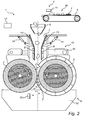
- a roller crusher 1 has two rollers 2, which extend horizontally and are arranged in parallel. Between them, the rollers define a crushing gap 3.
- the roller crusher 1 further comprises an in-feed arrangement 4, arranged above the rollers 2, including a conveyor 5, a hopper 6, a control gate 7, and guide plates 8.
- the roller crusher 1 also comprises a discharge arrangement 9, arranged below the rollers 2, including a discharge chute 10. At a position adjacent the conveyor 5, a first metal detector 11 is arranged, and at a position adjacent the discharge chute 10, a second metal detector 12 is arranged.
- the control gate 7 is constructed as a funnel having two pivotable sidewalls 13. Each sidewall is connected to a respective hydraulic cylinder 14.
- the roller crusher is provided with a gap adjuster 15 in the form of a hydraulic cylinder 16 connected to the rollers 2.
- roller crusher 1 comprises a control unit 17 operably connected to the first and second metal detectors 11, 12, to the control gate 7, and to the gap adjuster 15.
- the connection may be by wiring or wireless.
- Material M to be ground is fed by the conveyor 5 to the hopper 6.
- the material M to be ground or crushed passes through the control gate 7 and between the guide plates 8 to the gap 3 between the rollers.
- the material M to be ground is choke fed to the gap 3, i.e. pressure is added on the material currently being fed to the crushing gap by gravity acting on material above it.
- the material M is crushed and ground by crushing action of the rollers 2 and also by crushing action of particles in the material M itself, so called interparticle crushing.
- the roller crusher 1 has a protective system, which may be referred to as a tramp protection system.
- a protective system which may be referred to as a tramp protection system. The method by which the roller crusher 1 is protected from tramp objects, i.e. uncrushable objects, will now be described.
- an uncrushable object or tramp object T is present in the in-feed stream of material M.
- the uncrushable object T is of metallic character.
- the first metal detector 11 sends a first input signal to the control unit 17 indicating that an uncrushable object T has been detected.
- the control unit sends a first output signal to the hydraulic cylinders 14 of the control gate, prompting them to extend, thereby pivoting the pivotable side walls 13 such that they reduce the lower opening of the control gate 7.
- the in-feed rate to the gap 3 is reduced from an original operational in-feed rate to a restricted in-feed rate.
- the restricted in-feed rate may be, e.g., 30-50 % of the operational in-feed rate.
- the control unit 17 sends a second output signal to the gap adjuster 15, prompting the hydraulic cylinder 16 of the gap adjuster 15 to extend, thereby moving the rollers 2 apart, and hence, widening the gap 3 from an original operational width to a greater by-pass width.
- the by-pass width may be, e.g., three times the operational width.
- the by-pass width may, for instance, be at least three times the size of the biggest material expected in the in-feed flow, such that a free flow of material is ensured.
- the uncrushable object T is allowed to pass through the gap 3.
- the rollers 2 will not attempt to crush the uncrushable object, and thereby, the rollers 2 are protected from the uncrushable object T.
- the in-feed rate to the gap is reduced, and thereby time may be gained for being able to protect the rollers from the uncrushable object T, and less material M is allowed to pass uncrushed through the gap 3.
- the uncrushable object T If the uncrushable object T is small enough, it will pass through the control gate 7 even though the opening of the control gate 7 is reduced. However, since the crushing gap 3 is widened, the uncrushable object T will pass through the gap 3 without damaging the rollers 2. Should the uncrushable object T be too large to pass through the control gate 7 when the opening is reduced, then the opening of the control gate 7 may be increased again once the width of the crushing gap 3 has been increased to the by-pass width, such that the uncrushable object T may pass through the control gate 7, and then through the crushing gap 3 without damaging the rollers 2.
- the roller crusher 1 may be further adapted to protect the rollers from uncrushable objects T by decreasing the pressure with which the rollers 2 are pressed towards each other.
- the roller crusher 1 may be provided with a pressure adjuster (not shown).
- the uncrushable object T may be allowed to push one of the rollers 2 away from the other, or the rollers 2 away from each other, thereby increasing the width of the gap 3 further, such that the uncrushable object T may pass through.
- the pressure applied to the rollers 2 may once more be increased to an operational pressure.
- the second metal detector 12 detects the uncrushable object T.
- the second metal detector 12 sends a second input signal to the control unit 17.
- the control unit 17 sends a third output signal to the control gate 7, prompting the hydraulic cylinders 14 to retract, thereby pivoting the pivotable side walls 13 such that they increase the lower opening of the control gate 7.
- the control unit 17 sends a fourth output signal to the gap adjuster 15, prompting the hydraulic cylinder 16 of the gap adjuster 15 to retract, thereby moving the rollers 2 towards each other, and hence, once more reducing the gap 3 to the operational width.
- the second metal detector may be dispensed with.
- the determination that the uncrushable object has passed may be based on probability.
- a predetermined time measured by a timer in the control unit has passed after the first metal detector detected the presence of an uncrushable object, it may be assumed that the uncrushable object has passed through the gap.
- the predetermined time may be determined based on experimental data or calculated from the in-feed rate.
- the detectors used need not be metal detectors. If the roller crusher is to be protected not from metallic objects, but from overly large objects, a photocell, a radar equipment, or a laser sensor could be used for detecting objects that extend a predetermined height above an admissible height on the conveyor.
- the in-feed arrangement need not necessarily comprise a conveyor belt, but may employ another kind of conveyor, such as a screw conveyor or a chute.
- the discharge arrangement may take other forms than the one shown in the drawings, and may for instance comprise a conveyor belt onto which the crushed material is dropped.
- a diverting gate may be arranged in the discharge arrangement for removing tramp objects that have been by-passed.
- the control gate need not be in the form of a funnel having pivotable sidewalls.
- a funnel having a circular cross-section and flexible walls may be used, the restriction of the lower opening of the control gate being adjustable through a snare-like arrangement around the funnel.
- the control gate may be an inclined slide gate, having an a adjustable inclination, such that the flow rate may be adjusted.
- the hydraulic cylinder of the gap adjuster may also be used for controlling the gap width for adjustment to different compositions of the material to be ground.
- the gap adjuster may, instead of a hydraulic cylinder employ other mechanical means, such as gears and a gear rack.
- the adjustment of the width of the gap may be done by moving one of the rollers away from the other roller, which remains stationary, or by moving the two rollers away from each other.
- the operational in-feed rate and the operational gap width are normally not fixed, but adjustable depending on the material to be ground.
- the detector in the embodiment shown is illustrated as being arranged adjacent the in-feed conveyor, the detection of uncrushable objects could be done elsewhere in the in-feed stream of material to the roller crusher, e.g., at the rollers.
Description
- The present invention relates to a method of protecting a roller crusher from uncrushable objects. Further, the present invention relates to a roller crusher having a protective system for protection from uncrushable objects.
- When crushing or grinding rock, ore, cement clinker and other hard materials, roller crushers may be used having two generally parallel rolls which rotate in opposite directions and which are separated by a gap. The material to be crushed is fed by gravity or choke-fed into the gap. One type of roller crusher is called high pressure grinding rollers or high pressure roller crushers. This type of roller crusher uses a crushing technique called interparticle crushing. Here, the material to be crushed or pulverised is crushed, not only by the crushing surface of the rolls, but also by particles in the material to be crushed, hence the name interparticle crushing. One example of a high pressure grinding roller is described in
EP-516 952 - A problem which arises in roller crushers is that sometimes objects which are not possible to crush by the roller crusher are present in the in-feed stream of material. If an uncrushable object is fed into the gap of the roller crusher, the rollers and the system holding the rollers may be damaged, causing costs associated with down-time and repair. Therefore, roller crushers are sometimes provided with protective systems for protecting the roller crusher from uncrushable objects.
US-5263651-A andWO-98/32911-A Fig.1 , ametal detector 111 is provided at the in-feed 104 to theroller crusher 101. When themetal detector 111 detects an uncrushable object, a by-pass chute 118 is opened, such that the in-feed stream is diverted and by-passes thegap 103 between therollers 102. The by-pass stream is led to thesame discharge chute 110 as crushed material leaving the crushinggap 103. A problem with this solution is that during by-pass mode, thedischarge chute 110 receives at least twice the amount of material per unit of time as during normal operation, since the flow of the by-pass stream is added to the flow of crushed material. If several by-pass events occur within a short period of time, thedischarge chute 110 is overloaded, or else it has to be severely over dimensioned in relation to the normal operational flow of crushed material. Another problem is that the use of a by-pass chute 118 makes theroller crusher 101 space-requiring. Further, since the by-pass chute 118 is to discharge the by-passed material in thedischarge chute 110, thedischarge chute 110 needs to be placed at a distance from the exit of thegap 103, thereby adding to the space requirement of theroller crusher 101. Thus, a need remains for an improved method of protecting a roller crusher from uncrushable objects, and for a roller crusher having an improved protective system for protection from uncrushable objects. - It is an object of the present invention to overcome, or at least lessen, the above-mentioned problems.
- A particular object is to provide a method of protecting a roller crusher from uncrushable objects, which makes it possible to protect the roller crusher without adding to the size of it.
- Another object is to provide a roller crusher which may be protected from uncrushable objects without having to use a space-requiring by-pass chute.
- According to a first aspect, these and other objects are achieved, in full or at least in part, by a method of protecting a roller crusher from uncrushable objects, said roller crusher having two generally parallel rollers arranged to rotate in opposite directions and separated by a gap, said method comprising the steps of:
- detecting an uncrushable object in an in-feed stream of material to said roller crusher,
- opening a gap between said rollers to a by-pass width, which is significantly larger than an operational width, such that said uncrushable material is permitted to pass through said gap,
- restricting an in-feed to said gap, such that material is fed to said gap at a restricted in-feed rate,
- determining that said uncrushable object has passed through said gap,
- reducing said gap to said operational width, and
- opening said in-feed to said gap, such that material is fed to said gap at an operational in-feed rate. Such a method makes it possible to protect a roller crusher from uncrushable objects, without having to use a cumbersome by-pass chute. Further, the restriction of the in-feed rate makes it possible to gain some time for opening the gap, such that the roller crusher may be more securely protected. Determining when the uncrushable object has passed through the gap enables a quick return to normal operation.
- In a variant of the method, the uncrushable object comprises metal. Metallic objects are a common type of uncrushable objects which may damage the roller crusher seriously, and they are relatively easy to detect.
- The by-pass width may be greater than or equal to three times said operational width. Opening the gap to at least three times the operational width makes it possible to permit most uncrushable objects to pass unhindered through the gap.
- The restricted in-feed rate may be 30-50 % of said operational in-feed rate. In this manner, a suitable in-feed rate may be ensured.
- In a variant of the method, determining that said uncrushable object has passed through said gap comprises detecting said uncrushable object in a discharge stream of material from said roller crusher. Thereby, it may be ascertained that the uncrushable object has actually passed the gap, and normal operation of the roller crusher may safely be resumed.
- According to a second aspect, these and other objects are achieved, in full or at least in part, by a roller crusher having two generally parallel rollers arranged to rotate in opposite directions and separated by a gap, said roller crusher comprising
- an in-feed arrangement arranged to feed material to said roller crusher,
- a control gate arranged to control an in-feed rate to said gap,
- a first detector arranged to detect uncrushable objects,
- a gap adjuster arranged to adjust a width of said gap, and
- a control unit arranged to receive at least one input signal from said first detector, and to transmit at least one output signal to said control gate and to said gap adjuster. By this arrangement, the roller crusher is provided with a protective system that makes it possible to protect the roller crusher from uncrushable objects, without having to use a cumbersome by-pass chute. The control gate makes it possible to gain some time for opening the gap, such that the roller crusher may be more securely protected.
- In an embodiment, the first detector is a metal detector. A metal detector may be used for detecting metallic objects, which are a common type of uncrushable objects that may damage the roller crusher seriously.
- The roller crusher may comprise a second detector arranged to detect uncrushable objects. The second detector may be used for detecting the uncrushable object in a discharge stream of material from said roller crusher.
- The second detector may be a metal detector. Thereby, metallic objects may be securely detected.
- In an embodiment, the first detector is arranged to detect uncrushable objects in an in-feed stream of material to said roller crusher, and the second detector is arranged to detect uncrushable objects in a discharge stream of material from said roller crusher. This is advantageous in that it makes it possible to detect when an uncrushable object is about to enter the gap of the roller crusher, and to detect when the uncrushable object has passed through the gap.
- The gap adjuster may be arranged to adjust said gap in a width range from an operational width to a by-pass width, which is significantly larger than said operational width, preferably greater than or equal to three times said operational width. In this manner, it is possible to permit most uncrushable objects to pass unhindered through the gap.
- The control gate may be arranged to control said in-feed rate in a range from a restricted in-feed rate to an operational in-feed rate, said restricted in-feed rate being 30-50 % of said operational in-feed rate. In this manner, a suitable in-feed rate may be ensured.
- In an embodiment, the control unit is arranged to transmit a first output signal to said control gate, and to transmit a second output signal to said gap adjuster. Thereby, different control signals may be sent to the control gate and the gap adjuster.
- The control gate may be hydraulically operable, as may the gap adjuster. Hydraulic operation may be reliable and quick.
- Other objectives, features and advantages of the present invention will appear from the following detailed disclosure, from the attached claims, as well as from the drawings. It is noted that the invention relates to all possible combinations of features.
- Generally, all terms used in the claims are to be interpreted according to their ordinary meaning in the technical field, unless explicitly defined otherwise herein. All references to "a/an/the [element, device, component, means, step, etc.]" are to be interpreted openly as referring to at least one instance of said element, device, component, means, step, etc., unless explicitly stated otherwise. The steps of any method disclosed herein do not have to be performed in the exact order disclosed, unless explicitly stated.
- As used herein, the term "comprising" and variations of that term are not intended to exclude other additives, components, integers or steps.
- The invention will be described in more detail with reference to the appended schematic drawings, which show an example of a presently preferred embodiment of the invention.
-
Fig. 1 is a side view showing a roller crusher according to prior art. -
Fig. 2 is a side view showing an embodiment of a roller crusher during normal operation. -
Fig. 3 is a side view showing the roller crusher ofFig. 2 during a by-pass mode. - With reference to
Fig. 1 , aroller crusher 1 has tworollers 2, which extend horizontally and are arranged in parallel. Between them, the rollers define a crushinggap 3. Theroller crusher 1 further comprises an in-feed arrangement 4, arranged above therollers 2, including aconveyor 5, ahopper 6, acontrol gate 7, and guideplates 8. Theroller crusher 1 also comprises adischarge arrangement 9, arranged below therollers 2, including adischarge chute 10. At a position adjacent theconveyor 5, afirst metal detector 11 is arranged, and at a position adjacent thedischarge chute 10, asecond metal detector 12 is arranged. - The
control gate 7 is constructed as a funnel having twopivotable sidewalls 13. Each sidewall is connected to a respectivehydraulic cylinder 14. - The roller crusher is provided with a
gap adjuster 15 in the form of ahydraulic cylinder 16 connected to therollers 2. - Further, the
roller crusher 1 comprises acontrol unit 17 operably connected to the first andsecond metal detectors control gate 7, and to thegap adjuster 15. The connection may be by wiring or wireless. - The operation of the
roller crusher 1 will now be described. Material M to be ground is fed by theconveyor 5 to thehopper 6. The material M to be ground or crushed passes through thecontrol gate 7 and between theguide plates 8 to thegap 3 between the rollers. For high pressure roller crushing, the material M to be ground is choke fed to thegap 3, i.e. pressure is added on the material currently being fed to the crushing gap by gravity acting on material above it. The material M is crushed and ground by crushing action of therollers 2 and also by crushing action of particles in the material M itself, so called interparticle crushing. - The
roller crusher 1 has a protective system, which may be referred to as a tramp protection system. The method by which theroller crusher 1 is protected from tramp objects, i.e. uncrushable objects, will now be described. - In the example shown, an uncrushable object or tramp object T is present in the in-feed stream of material M. In this example, the uncrushable object T is of metallic character. Turning to
Fig. 2 , when the uncrushable object T passes thefirst metal detector 11, the uncrushable object T is detected by thefirst metal detector 11. Thefirst metal detector 11 sends a first input signal to thecontrol unit 17 indicating that an uncrushable object T has been detected. In response to the first input signal, the control unit sends a first output signal to thehydraulic cylinders 14 of the control gate, prompting them to extend, thereby pivoting thepivotable side walls 13 such that they reduce the lower opening of thecontrol gate 7. Thereby, the in-feed rate to thegap 3 is reduced from an original operational in-feed rate to a restricted in-feed rate. The restricted in-feed rate may be, e.g., 30-50 % of the operational in-feed rate. Additionally, thecontrol unit 17 sends a second output signal to thegap adjuster 15, prompting thehydraulic cylinder 16 of thegap adjuster 15 to extend, thereby moving therollers 2 apart, and hence, widening thegap 3 from an original operational width to a greater by-pass width. The by-pass width may be, e.g., three times the operational width. The by-pass width may, for instance, be at least three times the size of the biggest material expected in the in-feed flow, such that a free flow of material is ensured. - By widening the
gap 3 to the by-pass width, the uncrushable object T is allowed to pass through thegap 3. Therollers 2 will not attempt to crush the uncrushable object, and thereby, therollers 2 are protected from the uncrushable object T. - By reducing the opening of the
control gate 7, the in-feed rate to the gap is reduced, and thereby time may be gained for being able to protect the rollers from the uncrushable object T, and less material M is allowed to pass uncrushed through thegap 3. - If the uncrushable object T is small enough, it will pass through the
control gate 7 even though the opening of thecontrol gate 7 is reduced. However, since the crushinggap 3 is widened, the uncrushable object T will pass through thegap 3 without damaging therollers 2. Should the uncrushable object T be too large to pass through thecontrol gate 7 when the opening is reduced, then the opening of thecontrol gate 7 may be increased again once the width of the crushinggap 3 has been increased to the by-pass width, such that the uncrushable object T may pass through thecontrol gate 7, and then through the crushinggap 3 without damaging therollers 2. - The
roller crusher 1 may be further adapted to protect the rollers from uncrushable objects T by decreasing the pressure with which therollers 2 are pressed towards each other. To this end, theroller crusher 1 may be provided with a pressure adjuster (not shown). In this manner, if an overly large or unsymmetrical uncrushable object T enters the gap when it has been widened to the by-pass width, the uncrushable object T may be allowed to push one of therollers 2 away from the other, or therollers 2 away from each other, thereby increasing the width of thegap 3 further, such that the uncrushable object T may pass through. Once the uncrushable object T has passed through thegap 3, the pressure applied to therollers 2 may once more be increased to an operational pressure. - When the uncrushable object T has passed through the
gap 3, thesecond metal detector 12 detects the uncrushable object T. Thesecond metal detector 12 sends a second input signal to thecontrol unit 17. In response thereto, thecontrol unit 17 sends a third output signal to thecontrol gate 7, prompting thehydraulic cylinders 14 to retract, thereby pivoting thepivotable side walls 13 such that they increase the lower opening of thecontrol gate 7. Thereby, the in-feed rate to thegap 3 is once more increased to the operational in-feed rate. Additionally, thecontrol unit 17 sends a fourth output signal to thegap adjuster 15, prompting thehydraulic cylinder 16 of thegap adjuster 15 to retract, thereby moving therollers 2 towards each other, and hence, once more reducing thegap 3 to the operational width. - The skilled person realises that a number of modifications of the embodiments described herein are possible without departing from the scope of the invention, which is defined in the appended claims.
- For instance, the second metal detector may be dispensed with. Instead, the determination that the uncrushable object has passed may be based on probability. When a predetermined time measured by a timer in the control unit has passed after the first metal detector detected the presence of an uncrushable object, it may be assumed that the uncrushable object has passed through the gap. The predetermined time may be determined based on experimental data or calculated from the in-feed rate.
- Further, the detectors used need not be metal detectors. If the roller crusher is to be protected not from metallic objects, but from overly large objects, a photocell, a radar equipment, or a laser sensor could be used for detecting objects that extend a predetermined height above an admissible height on the conveyor.
- The in-feed arrangement need not necessarily comprise a conveyor belt, but may employ another kind of conveyor, such as a screw conveyor or a chute.
- The discharge arrangement may take other forms than the one shown in the drawings, and may for instance comprise a conveyor belt onto which the crushed material is dropped.
- A diverting gate may be arranged in the discharge arrangement for removing tramp objects that have been by-passed.
- The control gate need not be in the form of a funnel having pivotable sidewalls. For instance, a funnel having a circular cross-section and flexible walls may be used, the restriction of the lower opening of the control gate being adjustable through a snare-like arrangement around the funnel. The control gate may be an inclined slide gate, having an a adjustable inclination, such that the flow rate may be adjusted.
- The hydraulic cylinder of the gap adjuster may also be used for controlling the gap width for adjustment to different compositions of the material to be ground.
- The gap adjuster may, instead of a hydraulic cylinder employ other mechanical means, such as gears and a gear rack.
- The adjustment of the width of the gap may be done by moving one of the rollers away from the other roller, which remains stationary, or by moving the two rollers away from each other.
- It should be noted that the operational in-feed rate and the operational gap width are normally not fixed, but adjustable depending on the material to be ground.
- Although the detector in the embodiment shown is illustrated as being arranged adjacent the in-feed conveyor, the detection of uncrushable objects could be done elsewhere in the in-feed stream of material to the roller crusher, e.g., at the rollers.
Claims (15)
- A method of protecting a roller crusher from uncrushable objects, said roller crusher (1) having two generally parallel rollers (2) arranged to rotate in opposite directions and separated by a gap (3), said method comprising the steps of:detecting an uncrushable object (T) in an in-feed stream of material (M) to said roller crusher (1),opening said gap (3) between said rollers (2) to a by-pass width, which is significantly larger than an operational width, such that said uncrushable object (T) is permitted to pass through said gap (3),restricting an in-feed (7) to said gap (3), such that material (M) is fed to said gap (3) at a restricted in-feed rate,determining that said uncrushable object (T) has passed through said gap (3),reducing said gap (3) to said operational width, andopening said in-feed (7) to said gap (3), such that material (M) is fed to said gap (3) at an operational in-feed rate.
- A method as claimed in claim 1, wherein said uncrushable object (T) comprises metal.
- A method as claimed in claim 1 or 2, wherein said by-pass width is greater than or equal to three times said operational width.
- A method as claimed in any one of the preceding claims, wherein said restricted in-feed rate is 30-50 % of said operational in-feed rate.
- A method as claimed in any one of the preceding claims, wherein determining that said uncrushable object (T) has passed through said gap (3) comprises detecting said uncrushable object (T) in a discharge stream of material (M) from said roller crusher (1).
- A roller crusher having two generally parallel rollers (2) arranged to rotate in opposite directions and separated by a gap (3), said roller crusher (1) comprising:an in-feed arrangement (4) arranged to feed material (M) to said roller crusher (1),a control gate (7) arranged to control an in-feed rate to said gap (3),a first detector (11) arranged to detect uncrushable objects (T),a gap adjuster (15) arranged to adjust a width of said gap (3), anda control unit (17) arranged to receive at least one input signal from said first detector (11), and to transmit at least one output signal to said control gate (7) and to said gap adjuster (15).
- A roller crusher as claimed in claim 6, wherein said first detector is a metal detector (11).
- A roller crusher as claimed in claim 6 or 7, further comprising a second detector (12) arranged to detect uncrushable objects (T).
- A roller crusher as claimed in claim 8, wherein said second detector is a metal detector (12).
- A roller crusher as claimed in claim 8 or 9, wherein said first detector (11) is arranged to detect uncrushable objects (T) in an in-feed stream of material (M) to said roller crusher (1), and wherein said second detector (12) is arranged to detect uncrushable objects (T) in a discharge stream of material (M) from said roller crusher (1).
- A roller crusher as claimed in any one of claims 6-10, wherein said gap adjuster (15) is arranged to adjust said gap (3) in a width range from an operational width to a by-pass width, which is significantly larger than said operational width, preferably greater than or equal to three times said operational width.
- A roller crusher as claimed in any one of claims 6-11, wherein said control gate (7) is arranged to control said in-feed rate in a range from a restricted in-feed rate to an operational in-feed rate, said restricted in-feed rate being 30-50 % of said operational in-feed rate.
- A roller crusher as claimed in any one of claims 6-12, wherein said control unit (17) is arranged to transmit a first output signal to said control gate (7), and to transmit a second output signal to said gap adjuster (15).
- A roller crusher as claimed in any one of claims 6-13, wherein said control gate is hydraulically operable.
- A roller crusher as claimed in any one of claims 6-14, wherein said gap adjuster is hydraulically operable.
Applications Claiming Priority (1)
| Application Number | Priority Date | Filing Date | Title |
|---|---|---|---|
| US13/451,895 US8544774B1 (en) | 2012-04-20 | 2012-04-20 | Roller crusher, and method of protecting a roller crusher from uncrushable objects |
Publications (2)
| Publication Number | Publication Date |
|---|---|
| EP2653233A1 EP2653233A1 (en) | 2013-10-23 |
| EP2653233B1 true EP2653233B1 (en) | 2014-06-18 |
Family
ID=47351524
Family Applications (1)
| Application Number | Title | Priority Date | Filing Date |
|---|---|---|---|
| EP12197295.4A Active EP2653233B1 (en) | 2012-04-20 | 2012-12-14 | Roller crusher, and method of protecting a roller crusher from uncrushable objects |
Country Status (16)
| Country | Link |
|---|---|
| US (1) | US8544774B1 (en) |
| EP (1) | EP2653233B1 (en) |
| CN (2) | CN203281342U (en) |
| AR (1) | AR090758A1 (en) |
| AU (1) | AU2013203881B2 (en) |
| BR (1) | BR112014025989B8 (en) |
| CA (1) | CA2870881C (en) |
| CL (1) | CL2014002801A1 (en) |
| DK (1) | DK2653233T3 (en) |
| IN (1) | IN2014DN08779A (en) |
| MX (1) | MX339247B (en) |
| PE (1) | PE20150089A1 (en) |
| RU (1) | RU2606924C2 (en) |
| UA (1) | UA115660C2 (en) |
| WO (1) | WO2013156970A1 (en) |
| ZA (1) | ZA201408190B (en) |
Cited By (1)
| Publication number | Priority date | Publication date | Assignee | Title |
|---|---|---|---|---|
| DE102014018785A1 (en) | 2014-12-19 | 2016-06-23 | Thyssenkrupp Ag | crusher |
Families Citing this family (15)
| Publication number | Priority date | Publication date | Assignee | Title |
|---|---|---|---|---|
| DE112011104966T5 (en) * | 2011-02-25 | 2013-12-12 | Tna Australia Pty Ltd. | metal detector |
| DE102013106458A1 (en) * | 2013-06-20 | 2014-12-24 | Thyssenkrupp Industrial Solutions Ag | Roller mill for crushing brittle regrind |
| DE102013110981A1 (en) * | 2013-10-02 | 2015-04-02 | Thyssenkrupp Industrial Solutions Ag | A method of operating a plant having at least one aggregate having a rotating surface |
| CN103706431B (en) * | 2013-12-18 | 2016-04-20 | 铜陵迈臣机电科技有限责任公司 | A kind of high pressure double-roller extrusion mill |
| CN104001587A (en) * | 2014-06-03 | 2014-08-27 | 南京凯盛国际工程有限公司 | Novel material grinding device |
| US20160199841A1 (en) * | 2015-01-12 | 2016-07-14 | Kwok Fai Edmund SO | Ceramic material granulator |
| WO2016207714A1 (en) * | 2015-06-25 | 2016-12-29 | Rem Holding Limited | Waste compacting device |
| CN105879961B (en) * | 2016-05-06 | 2017-12-08 | 重庆市巴南区环美金属加工厂 | A kind of high-pressure roller mill of controllable particle size for chemical field |
| CN107952512A (en) * | 2017-10-20 | 2018-04-24 | 芜湖市鸿坤汽车零部件有限公司 | A kind of new rolling device |
| CN107670793A (en) * | 2017-10-31 | 2018-02-09 | 阴国富 | A kind of food waste powder crushing device provided with magnetic separation metal detecting system |
| CN108772134A (en) * | 2018-06-29 | 2018-11-09 | 衡阳泰源商砼有限公司 | A kind of ore pulverizer of adjustable rock fragments size |
| US11077446B2 (en) * | 2018-10-01 | 2021-08-03 | Metso Outotec USA Inc. | Startup sequence for roller crusher |
| CN109126960A (en) * | 2018-10-11 | 2019-01-04 | 福建铁拓机械有限公司 | A kind of oppositely rolling roller crusher and method of broken asphalt reclamation material |
| CN112892719A (en) * | 2021-01-29 | 2021-06-04 | 北京金隅琉水环保科技有限公司 | High-temperature blocking system of roller crusher |
| CN113231170B (en) * | 2021-06-04 | 2023-05-02 | 广州运龙消防设备有限公司 | Preparation process of aqueous acrylic emulsion |
Family Cites Families (20)
| Publication number | Priority date | Publication date | Assignee | Title |
|---|---|---|---|---|
| US3468488A (en) * | 1965-11-30 | 1969-09-23 | Buehler Ag Geb | Automatic control of feed material in a comminuting mill |
| US3606265A (en) * | 1969-04-03 | 1971-09-20 | Herbert T Cobey | Fragmentizing apparatus with vertically mounted drum |
| CH619157A5 (en) * | 1976-07-16 | 1980-09-15 | Buehler Ag Geb | |
| SU1079279A1 (en) * | 1982-06-24 | 1984-03-15 | Киевский Автомобильно-Дорожный Институт Им.60-Летия Великой Октябрьской Социалистической Революции | Apparatus for crushing |
| DE3305339A1 (en) * | 1983-02-17 | 1984-08-23 | Klöckner-Humboldt-Deutz AG, 5000 Köln | METHOD AND DEVICE FOR CONTINUOUS PRESSURE REDUCTION SPROEDEN GROSSGUTES |
| DE3535406A1 (en) * | 1985-10-03 | 1987-04-09 | Krupp Polysius Ag | Method and system for comminuting material for grinding |
| AT390210B (en) * | 1987-05-19 | 1990-04-10 | Kemetter Georg L | DEVICE FOR PROCESSING MATERIALS |
| US5060874A (en) * | 1990-08-16 | 1991-10-29 | Mclanahan Corporation | Crusher |
| RU2012399C1 (en) * | 1990-08-20 | 1994-05-15 | Научно-исследовательский проектно-конструкторский технологический институт механизации труда в черной металлургии и ремонтно-механических работ | Jaw crusher |
| DE4129882C2 (en) * | 1990-09-17 | 2002-02-07 | Truetzschler Gmbh & Co Kg | Device for separating metallic contaminants from a fiber transport path in the spinning preparation |
| CH682809A5 (en) * | 1990-12-12 | 1993-11-30 | Buehler Ag | Automatic product feed system, method for controlling the grinding of a Müllereiwalzenstuhles. |
| DE4132474A1 (en) | 1991-05-28 | 1992-12-03 | Kloeckner Humboldt Deutz Ag | WEAR-RESISTANT GRINDING ROLLER FOR USE IN ROLLING MACHINES, ESPECIALLY IN HIGH PRESSURE ROLLING PRESSES |
| JP3226107B2 (en) * | 1991-07-22 | 2001-11-05 | 株式会社栗本鐵工所 | Rotor shear crusher |
| US5263651A (en) * | 1992-04-01 | 1993-11-23 | Beloit Technologies, Inc. | Safety device for chip conditioning device |
| US5312052A (en) * | 1992-06-01 | 1994-05-17 | Dellekamp Michael D | Method for reclaiming fiber reinforcement from a composite |
| US5568896A (en) * | 1994-02-22 | 1996-10-29 | Beloit Technologies, Inc. | Methods for preparing pulpwood for digestion |
| US5865382A (en) * | 1997-01-24 | 1999-02-02 | Beloit Technologies, Inc. | Protection system for a wood chip destructuring device |
| DE202009013428U1 (en) * | 2009-10-05 | 2011-03-03 | Schwelling, Hermann | Shredder with metal detection |
| CN201592111U (en) * | 2010-01-20 | 2010-09-29 | 义乌市鑫隆机械实业有限公司 | Swing type double-roll crusher |
| SE1051348A1 (en) * | 2010-12-20 | 2012-05-22 | Sandvik Intellectual Property | Hydraulic circuit and method for controlling a gyratory cone crusher |
-
2012
- 2012-04-20 US US13/451,895 patent/US8544774B1/en active Active
- 2012-12-14 EP EP12197295.4A patent/EP2653233B1/en active Active
- 2012-12-14 DK DK12197295.4T patent/DK2653233T3/en active
-
2013
- 2013-04-11 AU AU2013203881A patent/AU2013203881B2/en active Active
- 2013-04-19 WO PCT/IB2013/053101 patent/WO2013156970A1/en active Application Filing
- 2013-04-19 CN CN2013201991106U patent/CN203281342U/en not_active Expired - Lifetime
- 2013-04-19 RU RU2014144232A patent/RU2606924C2/en active
- 2013-04-19 PE PE2014001673A patent/PE20150089A1/en active IP Right Grant
- 2013-04-19 BR BR112014025989A patent/BR112014025989B8/en active IP Right Grant
- 2013-04-19 IN IN8779DEN2014 patent/IN2014DN08779A/en unknown
- 2013-04-19 MX MX2014012699A patent/MX339247B/en active IP Right Grant
- 2013-04-19 UA UAA201411474A patent/UA115660C2/en unknown
- 2013-04-19 AR ARP130101303A patent/AR090758A1/en active IP Right Grant
- 2013-04-19 CN CN201380020769.3A patent/CN104364015B/en active Active
- 2013-04-19 CA CA2870881A patent/CA2870881C/en active Active
-
2014
- 2014-10-17 CL CL2014002801A patent/CL2014002801A1/en unknown
- 2014-11-10 ZA ZA2014/08190A patent/ZA201408190B/en unknown
Cited By (1)
| Publication number | Priority date | Publication date | Assignee | Title |
|---|---|---|---|---|
| DE102014018785A1 (en) | 2014-12-19 | 2016-06-23 | Thyssenkrupp Ag | crusher |
Also Published As
| Publication number | Publication date |
|---|---|
| CL2014002801A1 (en) | 2015-02-06 |
| CN203281342U (en) | 2013-11-13 |
| US20130277466A1 (en) | 2013-10-24 |
| RU2606924C2 (en) | 2017-01-10 |
| MX2014012699A (en) | 2015-06-03 |
| BR112014025989B1 (en) | 2020-12-08 |
| WO2013156970A1 (en) | 2013-10-24 |
| CN104364015A (en) | 2015-02-18 |
| PE20150089A1 (en) | 2015-02-12 |
| CA2870881A1 (en) | 2013-10-24 |
| AR090758A1 (en) | 2014-12-03 |
| UA115660C2 (en) | 2017-12-11 |
| EP2653233A1 (en) | 2013-10-23 |
| IN2014DN08779A (en) | 2015-05-22 |
| BR112014025989B8 (en) | 2023-03-07 |
| AU2013203881A1 (en) | 2013-11-07 |
| ZA201408190B (en) | 2016-09-28 |
| CN104364015B (en) | 2016-06-01 |
| MX339247B (en) | 2016-05-17 |
| US8544774B1 (en) | 2013-10-01 |
| AU2013203881B2 (en) | 2015-04-09 |
| RU2014144232A (en) | 2016-06-10 |
| BR112014025989A2 (en) | 2017-06-27 |
| CA2870881C (en) | 2017-01-17 |
| DK2653233T3 (en) | 2014-10-06 |
Similar Documents
| Publication | Publication Date | Title |
|---|---|---|
| EP2653233B1 (en) | Roller crusher, and method of protecting a roller crusher from uncrushable objects | |
| EP3589411B1 (en) | A control method of a treatment plant of elements to be recycled or disposed and a treatment plant of elements to be recycled or disposed | |
| EP2756886B1 (en) | Roller crusher having at least one roller comprising a flange | |
| CA2793262A1 (en) | Horizontal shaft impact crusher | |
| EP3122462B1 (en) | A jaw crusher, a crushing plant, and a method for using a jaw crusher | |
| US10493460B2 (en) | Roller crusher having at least one roller comprising a flange | |
| KR101585677B1 (en) | Apparatus for Treating Bulk Ore from Conveyer | |
| CN107670821A (en) | A kind of autogenous tumbling mill hard rock crushes and control system and method | |
| AU2013203833C1 (en) | Roller crusher having at least one roller comprising a flange | |
| EP2644275B1 (en) | Jaw crusher | |
| US7900778B2 (en) | Apparatus and method for the detection and rejection of metal in particulate material | |
| RU2021023C1 (en) | Method of crushing rock composition | |
| CN109650007A (en) | A kind of belt coal feeder that anchor pole, the detection of long material can be screened | |
| CN104773466B (en) | The exceeded sensing device of conveyer belt material containing block | |
| CN215242104U (en) | Polypropylene powder feeding device and polypropylene granulation equipment | |
| JP3166417B2 (en) | Control method of crusher | |
| US10589289B2 (en) | Method for controlling the operation of a crusher, a mineral material processing plant and a control system | |
| CN219990338U (en) | Detection device for immediately stopping tearing of transportation adhesive tape | |
| CN108996144A (en) | A kind of rubber conveyer |
Legal Events
| Date | Code | Title | Description |
|---|---|---|---|
| PUAI | Public reference made under article 153(3) epc to a published international application that has entered the european phase |
Free format text: ORIGINAL CODE: 0009012 |
|
| AK | Designated contracting states |
Kind code of ref document: A1 Designated state(s): AL AT BE BG CH CY CZ DE DK EE ES FI FR GB GR HR HU IE IS IT LI LT LU LV MC MK MT NL NO PL PT RO RS SE SI SK SM TR |
|
| AX | Request for extension of the european patent |
Extension state: BA ME |
|
| 17P | Request for examination filed |
Effective date: 20130918 |
|
| RBV | Designated contracting states (corrected) |
Designated state(s): AL AT BE BG CH CY CZ DE DK EE ES FI FR GB GR HR HU IE IS IT LI LT LU LV MC MK MT NL NO PL PT RO RS SE SI SK SM TR |
|
| GRAP | Despatch of communication of intention to grant a patent |
Free format text: ORIGINAL CODE: EPIDOSNIGR1 |
|
| RIC1 | Information provided on ipc code assigned before grant |
Ipc: B02C 4/32 20060101AFI20131210BHEP Ipc: B02C 23/04 20060101ALI20131210BHEP |
|
| INTG | Intention to grant announced |
Effective date: 20140109 |
|
| GRAS | Grant fee paid |
Free format text: ORIGINAL CODE: EPIDOSNIGR3 |
|
| GRAA | (expected) grant |
Free format text: ORIGINAL CODE: 0009210 |
|
| AK | Designated contracting states |
Kind code of ref document: B1 Designated state(s): AL AT BE BG CH CY CZ DE DK EE ES FI FR GB GR HR HU IE IS IT LI LT LU LV MC MK MT NL NO PL PT RO RS SE SI SK SM TR |
|
| REG | Reference to a national code |
Ref country code: GB Ref legal event code: FG4D |
|
| REG | Reference to a national code |
Ref country code: CH Ref legal event code: EP |
|
| REG | Reference to a national code |
Ref country code: AT Ref legal event code: REF Ref document number: 673025 Country of ref document: AT Kind code of ref document: T Effective date: 20140715 |
|
| REG | Reference to a national code |
Ref country code: IE Ref legal event code: FG4D |
|
| REG | Reference to a national code |
Ref country code: DE Ref legal event code: R096 Ref document number: 602012002151 Country of ref document: DE Effective date: 20140731 |
|
| REG | Reference to a national code |
Ref country code: DK Ref legal event code: T3 Effective date: 20140929 |
|
| REG | Reference to a national code |
Ref country code: SE Ref legal event code: TRGR |
|
| PG25 | Lapsed in a contracting state [announced via postgrant information from national office to epo] |
Ref country code: LT Free format text: LAPSE BECAUSE OF FAILURE TO SUBMIT A TRANSLATION OF THE DESCRIPTION OR TO PAY THE FEE WITHIN THE PRESCRIBED TIME-LIMIT Effective date: 20140618 Ref country code: NO Free format text: LAPSE BECAUSE OF FAILURE TO SUBMIT A TRANSLATION OF THE DESCRIPTION OR TO PAY THE FEE WITHIN THE PRESCRIBED TIME-LIMIT Effective date: 20140918 Ref country code: GR Free format text: LAPSE BECAUSE OF FAILURE TO SUBMIT A TRANSLATION OF THE DESCRIPTION OR TO PAY THE FEE WITHIN THE PRESCRIBED TIME-LIMIT Effective date: 20140919 Ref country code: CY Free format text: LAPSE BECAUSE OF FAILURE TO SUBMIT A TRANSLATION OF THE DESCRIPTION OR TO PAY THE FEE WITHIN THE PRESCRIBED TIME-LIMIT Effective date: 20140618 |
|
| REG | Reference to a national code |
Ref country code: NL Ref legal event code: VDEP Effective date: 20140618 |
|
| REG | Reference to a national code |
Ref country code: AT Ref legal event code: MK05 Ref document number: 673025 Country of ref document: AT Kind code of ref document: T Effective date: 20140618 |
|
| REG | Reference to a national code |
Ref country code: LT Ref legal event code: MG4D |
|
| PG25 | Lapsed in a contracting state [announced via postgrant information from national office to epo] |
Ref country code: RS Free format text: LAPSE BECAUSE OF FAILURE TO SUBMIT A TRANSLATION OF THE DESCRIPTION OR TO PAY THE FEE WITHIN THE PRESCRIBED TIME-LIMIT Effective date: 20140618 Ref country code: LV Free format text: LAPSE BECAUSE OF FAILURE TO SUBMIT A TRANSLATION OF THE DESCRIPTION OR TO PAY THE FEE WITHIN THE PRESCRIBED TIME-LIMIT Effective date: 20140618 Ref country code: HR Free format text: LAPSE BECAUSE OF FAILURE TO SUBMIT A TRANSLATION OF THE DESCRIPTION OR TO PAY THE FEE WITHIN THE PRESCRIBED TIME-LIMIT Effective date: 20140618 |
|
| PG25 | Lapsed in a contracting state [announced via postgrant information from national office to epo] |
Ref country code: EE Free format text: LAPSE BECAUSE OF FAILURE TO SUBMIT A TRANSLATION OF THE DESCRIPTION OR TO PAY THE FEE WITHIN THE PRESCRIBED TIME-LIMIT Effective date: 20140618 Ref country code: CZ Free format text: LAPSE BECAUSE OF FAILURE TO SUBMIT A TRANSLATION OF THE DESCRIPTION OR TO PAY THE FEE WITHIN THE PRESCRIBED TIME-LIMIT Effective date: 20140618 Ref country code: ES Free format text: LAPSE BECAUSE OF FAILURE TO SUBMIT A TRANSLATION OF THE DESCRIPTION OR TO PAY THE FEE WITHIN THE PRESCRIBED TIME-LIMIT Effective date: 20140618 Ref country code: PT Free format text: LAPSE BECAUSE OF FAILURE TO SUBMIT A TRANSLATION OF THE DESCRIPTION OR TO PAY THE FEE WITHIN THE PRESCRIBED TIME-LIMIT Effective date: 20141020 Ref country code: SK Free format text: LAPSE BECAUSE OF FAILURE TO SUBMIT A TRANSLATION OF THE DESCRIPTION OR TO PAY THE FEE WITHIN THE PRESCRIBED TIME-LIMIT Effective date: 20140618 Ref country code: RO Free format text: LAPSE BECAUSE OF FAILURE TO SUBMIT A TRANSLATION OF THE DESCRIPTION OR TO PAY THE FEE WITHIN THE PRESCRIBED TIME-LIMIT Effective date: 20140618 |
|
| PG25 | Lapsed in a contracting state [announced via postgrant information from national office to epo] |
Ref country code: PL Free format text: LAPSE BECAUSE OF FAILURE TO SUBMIT A TRANSLATION OF THE DESCRIPTION OR TO PAY THE FEE WITHIN THE PRESCRIBED TIME-LIMIT Effective date: 20140618 Ref country code: NL Free format text: LAPSE BECAUSE OF FAILURE TO SUBMIT A TRANSLATION OF THE DESCRIPTION OR TO PAY THE FEE WITHIN THE PRESCRIBED TIME-LIMIT Effective date: 20140618 Ref country code: AT Free format text: LAPSE BECAUSE OF FAILURE TO SUBMIT A TRANSLATION OF THE DESCRIPTION OR TO PAY THE FEE WITHIN THE PRESCRIBED TIME-LIMIT Effective date: 20140618 Ref country code: IS Free format text: LAPSE BECAUSE OF FAILURE TO SUBMIT A TRANSLATION OF THE DESCRIPTION OR TO PAY THE FEE WITHIN THE PRESCRIBED TIME-LIMIT Effective date: 20141018 |
|
| REG | Reference to a national code |
Ref country code: DE Ref legal event code: R097 Ref document number: 602012002151 Country of ref document: DE |
|
| PLBE | No opposition filed within time limit |
Free format text: ORIGINAL CODE: 0009261 |
|
| STAA | Information on the status of an ep patent application or granted ep patent |
Free format text: STATUS: NO OPPOSITION FILED WITHIN TIME LIMIT |
|
| PG25 | Lapsed in a contracting state [announced via postgrant information from national office to epo] |
Ref country code: IT Free format text: LAPSE BECAUSE OF FAILURE TO SUBMIT A TRANSLATION OF THE DESCRIPTION OR TO PAY THE FEE WITHIN THE PRESCRIBED TIME-LIMIT Effective date: 20140618 |
|
| 26N | No opposition filed |
Effective date: 20150319 |
|
| PG25 | Lapsed in a contracting state [announced via postgrant information from national office to epo] |
Ref country code: BE Free format text: LAPSE BECAUSE OF FAILURE TO SUBMIT A TRANSLATION OF THE DESCRIPTION OR TO PAY THE FEE WITHIN THE PRESCRIBED TIME-LIMIT Effective date: 20140618 |
|
| PG25 | Lapsed in a contracting state [announced via postgrant information from national office to epo] |
Ref country code: LU Free format text: LAPSE BECAUSE OF FAILURE TO SUBMIT A TRANSLATION OF THE DESCRIPTION OR TO PAY THE FEE WITHIN THE PRESCRIBED TIME-LIMIT Effective date: 20141214 Ref country code: SI Free format text: LAPSE BECAUSE OF FAILURE TO SUBMIT A TRANSLATION OF THE DESCRIPTION OR TO PAY THE FEE WITHIN THE PRESCRIBED TIME-LIMIT Effective date: 20140618 |
|
| REG | Reference to a national code |
Ref country code: IE Ref legal event code: MM4A |
|
| REG | Reference to a national code |
Ref country code: FR Ref legal event code: ST Effective date: 20150831 |
|
| PG25 | Lapsed in a contracting state [announced via postgrant information from national office to epo] |
Ref country code: IE Free format text: LAPSE BECAUSE OF NON-PAYMENT OF DUE FEES Effective date: 20141214 |
|
| PG25 | Lapsed in a contracting state [announced via postgrant information from national office to epo] |
Ref country code: FR Free format text: LAPSE BECAUSE OF NON-PAYMENT OF DUE FEES Effective date: 20141231 |
|
| PG25 | Lapsed in a contracting state [announced via postgrant information from national office to epo] |
Ref country code: MC Free format text: LAPSE BECAUSE OF FAILURE TO SUBMIT A TRANSLATION OF THE DESCRIPTION OR TO PAY THE FEE WITHIN THE PRESCRIBED TIME-LIMIT Effective date: 20140618 |
|
| PG25 | Lapsed in a contracting state [announced via postgrant information from national office to epo] |
Ref country code: BG Free format text: LAPSE BECAUSE OF FAILURE TO SUBMIT A TRANSLATION OF THE DESCRIPTION OR TO PAY THE FEE WITHIN THE PRESCRIBED TIME-LIMIT Effective date: 20140618 |
|
| PG25 | Lapsed in a contracting state [announced via postgrant information from national office to epo] |
Ref country code: TR Free format text: LAPSE BECAUSE OF FAILURE TO SUBMIT A TRANSLATION OF THE DESCRIPTION OR TO PAY THE FEE WITHIN THE PRESCRIBED TIME-LIMIT Effective date: 20140618 Ref country code: MT Free format text: LAPSE BECAUSE OF FAILURE TO SUBMIT A TRANSLATION OF THE DESCRIPTION OR TO PAY THE FEE WITHIN THE PRESCRIBED TIME-LIMIT Effective date: 20140618 Ref country code: HU Free format text: LAPSE BECAUSE OF FAILURE TO SUBMIT A TRANSLATION OF THE DESCRIPTION OR TO PAY THE FEE WITHIN THE PRESCRIBED TIME-LIMIT; INVALID AB INITIO Effective date: 20121214 |
|
| REG | Reference to a national code |
Ref country code: CH Ref legal event code: PL |
|
| PG25 | Lapsed in a contracting state [announced via postgrant information from national office to epo] |
Ref country code: CH Free format text: LAPSE BECAUSE OF NON-PAYMENT OF DUE FEES Effective date: 20151231 Ref country code: LI Free format text: LAPSE BECAUSE OF NON-PAYMENT OF DUE FEES Effective date: 20151231 |
|
| PG25 | Lapsed in a contracting state [announced via postgrant information from national office to epo] |
Ref country code: SM Free format text: LAPSE BECAUSE OF FAILURE TO SUBMIT A TRANSLATION OF THE DESCRIPTION OR TO PAY THE FEE WITHIN THE PRESCRIBED TIME-LIMIT Effective date: 20140618 |
|
| GBPC | Gb: european patent ceased through non-payment of renewal fee |
Effective date: 20161214 |
|
| PG25 | Lapsed in a contracting state [announced via postgrant information from national office to epo] |
Ref country code: GB Free format text: LAPSE BECAUSE OF NON-PAYMENT OF DUE FEES Effective date: 20161214 |
|
| PG25 | Lapsed in a contracting state [announced via postgrant information from national office to epo] |
Ref country code: MK Free format text: LAPSE BECAUSE OF FAILURE TO SUBMIT A TRANSLATION OF THE DESCRIPTION OR TO PAY THE FEE WITHIN THE PRESCRIBED TIME-LIMIT Effective date: 20140618 |
|
| PG25 | Lapsed in a contracting state [announced via postgrant information from national office to epo] |
Ref country code: AL Free format text: LAPSE BECAUSE OF FAILURE TO SUBMIT A TRANSLATION OF THE DESCRIPTION OR TO PAY THE FEE WITHIN THE PRESCRIBED TIME-LIMIT Effective date: 20140618 |
|
| REG | Reference to a national code |
Ref country code: DE Ref legal event code: R081 Ref document number: 602012002151 Country of ref document: DE Owner name: METSO OUTOTEC USA INC., BROOKFIELD, US Free format text: FORMER OWNER: METSO MINERALS INDUSTRIES, INC., WAUKESHA, WIS., US |
|
| P01 | Opt-out of the competence of the unified patent court (upc) registered |
Effective date: 20230527 |
|
| PGFP | Annual fee paid to national office [announced via postgrant information from national office to epo] |
Ref country code: SE Payment date: 20231110 Year of fee payment: 12 Ref country code: FI Payment date: 20231218 Year of fee payment: 12 Ref country code: DK Payment date: 20231214 Year of fee payment: 12 Ref country code: DE Payment date: 20231031 Year of fee payment: 12 |