EP2652563B1 - Verfahren und vorrichtung für den erhalt einer kontinuierlichen bewegung einer anzeigevorrichtung - Google Patents
Verfahren und vorrichtung für den erhalt einer kontinuierlichen bewegung einer anzeigevorrichtung Download PDFInfo
- Publication number
- EP2652563B1 EP2652563B1 EP11793746.6A EP11793746A EP2652563B1 EP 2652563 B1 EP2652563 B1 EP 2652563B1 EP 11793746 A EP11793746 A EP 11793746A EP 2652563 B1 EP2652563 B1 EP 2652563B1
- Authority
- EP
- European Patent Office
- Prior art keywords
- display means
- movement
- sensor
- velocity
- simulated
- Prior art date
- Legal status (The legal status is an assumption and is not a legal conclusion. Google has not performed a legal analysis and makes no representation as to the accuracy of the status listed.)
- Active
Links
- 238000000034 method Methods 0.000 title claims description 14
- 230000004913 activation Effects 0.000 claims description 36
- 230000001133 acceleration Effects 0.000 claims description 32
- 239000012530 fluid Substances 0.000 claims description 19
- 238000007781 pre-processing Methods 0.000 claims description 3
- 230000003213 activating effect Effects 0.000 claims 2
- 238000011144 upstream manufacturing Methods 0.000 claims 1
- 238000001994 activation Methods 0.000 description 31
- 238000004364 calculation method Methods 0.000 description 17
- 238000012937 correction Methods 0.000 description 15
- 230000008901 benefit Effects 0.000 description 7
- 230000006870 function Effects 0.000 description 6
- 230000002035 prolonged effect Effects 0.000 description 6
- 238000005070 sampling Methods 0.000 description 5
- 238000004088 simulation Methods 0.000 description 5
- 238000010586 diagram Methods 0.000 description 4
- 230000002779 inactivation Effects 0.000 description 4
- 238000004422 calculation algorithm Methods 0.000 description 3
- 230000008859 change Effects 0.000 description 3
- 230000000694 effects Effects 0.000 description 3
- 239000007787 solid Substances 0.000 description 3
- 230000006399 behavior Effects 0.000 description 2
- 230000036461 convulsion Effects 0.000 description 2
- 210000000056 organ Anatomy 0.000 description 2
- 208000031968 Cadaver Diseases 0.000 description 1
- 241001080024 Telles Species 0.000 description 1
- 241000897276 Termes Species 0.000 description 1
- 240000008042 Zea mays Species 0.000 description 1
- 230000009471 action Effects 0.000 description 1
- 230000003247 decreasing effect Effects 0.000 description 1
- 230000001419 dependent effect Effects 0.000 description 1
- 238000001514 detection method Methods 0.000 description 1
- 238000006073 displacement reaction Methods 0.000 description 1
- 238000010494 dissociation reaction Methods 0.000 description 1
- 230000005593 dissociations Effects 0.000 description 1
- 229940082150 encore Drugs 0.000 description 1
- 235000021183 entrée Nutrition 0.000 description 1
- 239000004973 liquid crystal related substance Substances 0.000 description 1
- 238000004519 manufacturing process Methods 0.000 description 1
- 230000007246 mechanism Effects 0.000 description 1
- 239000002184 metal Substances 0.000 description 1
- 238000003825 pressing Methods 0.000 description 1
- 230000008569 process Effects 0.000 description 1
- 230000009467 reduction Effects 0.000 description 1
- 230000003362 replicative effect Effects 0.000 description 1
- 230000004044 response Effects 0.000 description 1
- 230000002441 reversible effect Effects 0.000 description 1
- 238000009738 saturating Methods 0.000 description 1
- 239000003381 stabilizer Substances 0.000 description 1
- 230000002123 temporal effect Effects 0.000 description 1
- 230000009466 transformation Effects 0.000 description 1
- 230000000007 visual effect Effects 0.000 description 1
Images


Classifications
-
- G—PHYSICS
- G04—HOROLOGY
- G04C—ELECTROMECHANICAL CLOCKS OR WATCHES
- G04C3/00—Electromechanical clocks or watches independent of other time-pieces and in which the movement is maintained by electric means
- G04C3/14—Electromechanical clocks or watches independent of other time-pieces and in which the movement is maintained by electric means incorporating a stepping motor
- G04C3/146—Electromechanical clocks or watches independent of other time-pieces and in which the movement is maintained by electric means incorporating a stepping motor incorporating two or more stepping motors or rotors
-
- G—PHYSICS
- G04—HOROLOGY
- G04G—ELECTRONIC TIME-PIECES
- G04G21/00—Input or output devices integrated in time-pieces
- G04G21/02—Detectors of external physical values, e.g. temperature
Definitions
- the present invention relates to the field of display devices, and in particular electromechanical timepieces provided with an analog-type display.
- time-setting devices actuated by a crown kinematically connected to the minute-gear train of the watch in its axial position corresponding to the setting mode are known. time, with determined gear train ratios to move the minute hand simply and quickly without having to rotate the crown either too long or often.
- the Swiss patent CH 641630 describes an electronic device for scrolling symbols at a variable speed in response to the activation of a sensor (movement of a finger on a touch sensor, pressure on a push button).
- the number of activations of the sensors and the duration of these activations have the effect of incrementing or decrementing the values contained in a register, which in turn determine a proportional scrolling speed. Decrementing the register values after a prolonged inactivation of the sensors makes it possible to gradually decrease the scrolling speed; however, this slowing down of the scrolling speed still lacks fluidity since the relative variations of the scrolling speed are all the greater the closer the register values are to zero.
- This solution has the advantage of using sensors without mechanical parts; the disadvantage is that the use is less intuitive than a traditional crown. Moreover, this solution relates only to digital displays and does not apply to watches comprising analog display members.
- the document CH 702 862 A1 describes a digital display timepiece comprising, in the embodiment of the figure 4 , a physical crown.
- a user's action on the crown is detected and the timepiece's processor uses this information, in combination with other measured/simulated force/torque values, to perform a simulation of the actual position of the components of a simulated mechanical watch movement.
- the figure 4 of this document that a simulation at all times of the position of the (virtual) components of a mechanical movement is displayed on the digital display device of the timepiece.
- virtual masses, inertias and elasticities are assigned to the displayed virtual components.
- An object of the present invention is therefore to propose a solution free from the aforementioned drawbacks of the prior art.
- an object of the present invention is to propose a more fluid and more intuitive display device for the user.
- An advantage of the proposed solution is to make the adjustment operation on the one hand more efficient, and on the other hand visually more intuitive thanks to the emulation of a Newtonian movement for the display means, i.e. that is, whose speed is continuous with acceleration and deceleration proportional to an applied torque or force. It is thus possible to adjust the scrolling speed to the magnitude of the correction, by first performing a coarse adjustment then a finer adjustment when approaching the desired value, with a speed that is always continuous.
- An additional advantage of the proposed solution is that it does not require any particular sensor resolution to increment the display values.
- the fluidity of the adjustment is ensured in particular by the fact that it is not a correction speed which is deduced from the movements of a control member, or detected by a sensor, but the acceleration of the display means. This therefore makes it possible to generate a continuous speed of these display means, in accordance with the movement of a mechanical member according to Newtonian laws of physics. This speed presents only small variations between different periods of actuation of the control member, and the proposed solution therefore does not undergo any threshold effect at the level of the sensor resulting in jerks for the movements of the control members. 'display.
- Another advantage of the proposed solution is also to minimize the manipulations necessary for adjustment, only a few sporadic activations of the control member being necessary to adjust the position of the display elements. Furthermore the control of Adjustment operations are improved thanks to the possibility of acting not only to accelerate the speed of correction but also to decelerate this same speed.
- An additional advantage of the proposed solution is to allow simultaneous adjustment of several display parameters, unlike the usual sequential adjustments for electronic watches.
- the time saved by the invention for the correction thanks to a continuous movement of the display means between the periods of actuation of the activation means gives the possibility of moving, for example, the hour and minute hands at the same time. , following the intuitive approach of a classic mechanical watch, without large-scale correction taking too long in the eyes of the user.
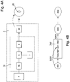
- a preferred embodiment of the control device of the invention is intended for timepieces and is illustrated in the figures 1A and 1B , which respectively show the logical structure of the control device 3 as well as the different parameters used and the different calculation steps carried out by various elements of the control device 3 to transform the movement of the activation means 1 into a non-proportional movement of the means display, unlike a traditional mechanical cog.
- the Figure 1A shows the preferential structure of the activation means 1, in the form of a crown 11, the actuation of which can be performed in two opposite directions of rotation S1 and S2, as well as that of the display means 2, in the form an hour hand 22 and a minute hand 21.
- the control device 3 according to the invention to other types of rotating mechanical display members 2, such as for example rings or drums.
- the invention therefore makes it possible to transform a first angular speed 111, corresponding to that of the drive of the crown 11 in a given direction of rotation, for example S1, into another angular speed 211 of the minute hand 21.
- the two angular speeds 111 and 211 are not proportional, since the minute hand 211 is progressively accelerated following the actuation of the crown 11 in the direction S1 in accordance with a Newtonian equation of movement 700 described later, which allows elsewhere to give a continuous character to the movement of the needles.
- the control device 3 comprises an electronic circuit 31 preferably in the form of an integrated circuit comprising a processing unit 5, comprising for example a microcontroller, and a motor control circuit 6.
- the microcontroller transforms digital input parameters, provided by a counter module 44 at the output of a first sensor 4 of movements of the activation means 1, i.e. for example the rotation of the crown 11, into instructions for the motor control circuit 6, such as for example a number of not motors.
- the counter module 44 makes it possible to transform the electrical signals produced by the first sensor 4 into discrete digital values, and therefore manipulable by a software processing unit 5 such as a microcontroller. However, the latter is not described in detail because it is known to those skilled in the art.
- control circuit 6 controls two separate motors, a first motor 61 being dedicated to controlling the movements of the minute hand 21, and a second motor 62 being dedicated to controlling the hour hand 22
- the control device 3 thus simultaneously actuates a plurality of motors 61, 62 each dedicated to distinct mechanical display means.
- the dissociation of the motors makes it possible to quickly change the display mode, by indicating, for example, the time of an alarm, or the direction of the earth's magnetic field.
- the activation means 1 are preferably mechanical; however, they can also take the form, for example, of a capacitive sensor, such as a touch screen.
- the actuation of the activation means 1 makes it possible to impart a variable and continuous movement to the display means 2, and in particular the minute hand 21, thanks to the calculation of an acceleration 703' in proportion to a torque value 401 'determined at the output of the first sensor 4, in proportion to the values of the register of the counter module 44, which makes it possible to characterize the movement of the activation means 1, preferably a crown 11, by digital values, namely a number of pulses .
- the step of determining a pulse frequency 4001 is a digitization process necessary to provide an input parameter that can be manipulated by the electronic circuit 31, which can then simulate the movement of the mechanical display means as if it were determined by the application of a torque 401' proportional to the frequency of pulses 401.
- the actual movement of the hands is considered Newtonian because it corresponds to that of a rotating solid subject to the fundamental relationship of the dynamics, indicating that the acceleration of a rotating body is proportional to the sum of the torques applied to it.
- the fundamental dynamic equation could also be applied to linear, and not rotary, display means 2, in which case the acceleration would be proportional to the sum of the forces applied to the system.
- the movement of the 21 minute hand is determined by solving Newton's first equation of motion 700 which models this fundamental equation of solid dynamics using a first coefficient 701 determining the torque 401' applied to the system from the pulse frequency 401, and as well as, according to a preferred embodiment, a second coefficient 702 determining a so-called fluid friction torque because causing a deceleration of the speed of rotation of the hands proportionally to this same speed.
- the actual movement of the hands is also considered inertial because it corresponds to that of a solid in rotation which is no longer subject, as soon as the crown 11 is no longer activated, to a so-called fluid friction torque, proportional to its rotational speed itself, causing them to gradually slow down.
- this fluid friction torque 703" is however fictitious, and simulated by the microcontroller 5 within the framework of the Newtonian equation 700 above; it is moreover not applied directly to the minute hand 21, but at the simulated speed of minute hand 703 also used to solve Newtonian equation 700 above.
- the method for determining the speed of the display means 2 therefore solves a Newtonian equation of motion by using torque and/or force values as input parameters for the resolution of this equation.
- These parameters are themselves determined in relation to a physical quantity, here the angular speed 111 of the crown 11, which is transformed via the first sensor 4 and the counter module 44 into a pulse frequency 401.
- other physical quantities can however be used within the scope of the invention, such as for example a linear or angular speed, a magnetic field or a geometric angle.
- the embodiment relating to an electronic compass described in relation to the figures 4A and 4B , uses the geometric angle as an input parameter delivered to the processing unit to determine a torque to be applied to the needle 23 indicating magnetic north.
- the angular speed of the hands is necessarily limited due to the constraints of the system in terms of processing capabilities.
- the first and second motors 61, 62 can only implement a given maximum number of steps per second, and there is therefore always a maximum frequency of motor steps from which the Newtonian equation of motion 700 does not can no longer be applied, because the angular acceleration necessarily becomes zero.
- the maximum frequency of motor steps 611' of the first motor 61 controlling the minute hand 21 is preferably between 200 and 1000 Hz, which corresponds to the maximum speed of rotation of the minute hand 21 between approximately one and five revolutions per second when a complete turn of the dial corresponds to 180 motor steps. It may be noted that whatever the embodiment chosen for the invention involving the use of an electronic circuit 31, a maximum scrolling speed of the mechanical display means 2 must always be defined according to the processing capacities of the motor control circuit 6.
- the figure 2A shows a preferred embodiment of the first sensor 4 according to the invention, which makes it possible to relatively simply determine a pulse frequency 401 used by the electronic circuit 31 in order to calculate the acceleration and/or deceleration values of the display means 1 by solving the first Newtonian equation 700 applied to this input parameter.
- the first sensor 4 is mounted on a rod 41, fixed in rotation to the crown 11, and which can be driven in rotation in two opposite directions S1 and S2.
- On the periphery of this rod 41 are mounted a plurality of electrical contactors 41a, 41b, 41c, 41d, preferably 4 in number, as illustrated in the figure 2A .
- the first sensor 4 also comprises two electrical contacts 42, 43 mounted on a fixed structure, a first contact 42 at the terminals of which is measured the value of a signal 412 of output and a second contact 43 across which the value of an output signal 413 is measured when a voltage is applied to the electrical contactors 41a, 41b, 41c, 41d.
- the figure 2B shows, in the upper part (a), the first and second signals 412 and 413 obtained during a rotation of the crown 11 in the direction of rotation S1, corresponding to the clockwise direction.
- the first period 401a corresponding to the duration during which each signal 412, 413 is positive
- the second period 401b during which each signal 412, 413 is zero
- the third total period 401c corresponding to the sum of the first and second periods 401a, 401b are identical for each of the first and second output signals 412, 413, which are simply shifted in time by a value corresponding to the path of one of the electrical contacts 41a, 41b, 41c, 41d from the first contact 42 to the 2nd contact 43 external.
- the use of the first contactor of the figure 2A to determine the frequency of pulses 401 applied to the first Newtonian equation 700 also has the advantage of not requiring any fine resolution of the first sensor 4 to guarantee the fluidity of the correction, since the speed determined by solving a Newtonian equation is always continues even if the acceleration is not.
- a less fine resolution of the granularity of the torque values, proportional to the frequency of pulses 401 will not have the consequence of causing the display means 2 to advance jerkily, but simply of generating sharper accelerations following the detection of each additional pulse.
- the picture 3 shows a state diagram for different sequences of time adjustment operations using hands according to a preferred embodiment of the invention applied to a timepiece.
- Those skilled in the art will understand that it is however possible to adjust other types of parameters that are not necessarily temporal (that is to say any type of symbol) and that the hands could be replaced by other analog display devices.
- Step 1001 corresponds to a first activation of crown 11, which makes it possible to generate the movement of minute hand 21.
- the first sensor 4 detects a “positive” number of pulses 401 corresponding to a positive angular speed 111 for crown 11 and simulates the application of a torque, applied to the needle in the same direction.
- the rotation of the crown 11 in the clockwise direction S1 makes it possible to advance the minute hand 21 on the dial.
- a maximum simulated angular speed 7031 is determined as a function of the maximum motor step frequency 611'. As soon as the algorithm solving the Newtonian equation reaches this upper speed limit, it saturates, that is to say stops increasing the simulated angular speed 703 even if the algorithm were to give a result of a value superior.
- the diagram of the picture 3 illustrates the comparison step 5003 performed by the microcontroller 5 to determine whether the speed is saturating, in which case the simulated angular speed 703 is limited to the maximum value 7031 and the angular acceleration 703' is zero for the sampling period over which the calculation has been made.
- the feedback loop starting from the comparison step 5003 towards a positive acceleration value 703' indicates that no saturation takes place until the maximum simulated angular velocity 7031 has not been reached.
- step 1001 has been described in the context of an activation of the crown 11 in the direction of rotation S1 of the hands of a watch to preferably advance the minute hand 21 in the same direction, it is possible also ensure that an activation of the crown 11 in the reverse direction S2 similarly rotates the minute 21 and hour 22 hands in the opposite direction, the number of pulses 401 being calculated identically for each period sampling but the information on the direction of rotation determined by the first sensor 4 makes it possible to choose the direction of rotation applied to the needles by the first and second motors 61, 62.
- the solution proposed here according to which the movement applied to the mechanical display means is the result of an acceleration which depends on the speed of the crown, is very robust in the face of a low resolution crown. Moreover, the movement remains fluid, even if the user advances the crown in jerks: if a user rotates the crown in successive strokes, the corrections continue between the strokes. This provides significant time savings in the case where the mechanical display means are not very efficient.
- a simultaneous adjustment of the hour hand 22 and the minute hand 21 in accordance with a totally mechanical approach, according to which the minute hand performs a complete rotation for each time change, is made possible at a speed acceptable to the user even for a relatively slow system.
- the activation step 1001 consequently makes it possible to simultaneously adjust the hour hand 22 and the minute hand 21, which is particularly advantageous for watches electronics where each parameter is usually set sequentially for performance reasons.
- Step 1001' is a step subordinate to step 1001, or more generally any activation step, which it immediately follows. This is a step during which crown 11, or more generally control means 1, ceases to be activated. During this step, the modeling of the invention means that no more external torque is applied to the system as soon as the detected pulse frequency 401 is zero, which depends among other things on the sampling period chosen at the level of the counter module 44 to determine the pulse frequency 401.
- the resolution of this Newtonian equation 700 determines the inertial type deceleration of the display member, such as for example the minute hand 21 in the embodiment described above, because the deceleration is only proportional to the simulated angular speed 703 During this inertial-type deceleration, the system is in the first deceleration phase B1 illustrated in figure picture 3 .
- the crown 11 is turned in the opposite direction S2 during an additional actuation step 1002, the angular acceleration 703' is still negative, but the B2 deceleration, shown on the picture 3 , is more pronounced because the sign of the dummy torque 401' becomes negative, acting with the angular acceleration 703' to slow the system more quickly.
- Actuation of the crown 11 in the opposite direction makes it possible to further refine the adjustment using the additional activation step 1002 when approaching a desired value while the angular speed is at this moment there relatively high, because the second phase of deceleration B2 which is generated is more pronounced than the first phase of deceleration B1 which occurs only during prolonged inactivation of the crown 11.
- the first activation step 1001 is therefore always followed by an acceleration phase A of the mechanical display means 2, and firstly the minute hand 21 for which the acceleration is the most perceptible.
- This acceleration phase A ends as soon as the motor control circuit 6 detects that a maximum frequency has been reached, in this case that of step 611′ of the first motor 61, in which case a phase follows. C during which the simulated angular speed 703 is limited to the maximum angular speed value 7031. During this phase C, the minute hand 21 is therefore constant, limited by the maximum step frequency 611' of the first motor 61: the algorithm saturates.
- any additional activation of crown 11 in the same direction of rotation S1 therefore has no impact on the real angular speed 211 of the minute hand; however, such activations make it possible to maintain the actual angular velocity 211 at this constant level by preventing the angular acceleration value 703' from becoming negative after too prolonged inactivation, corresponding according to the preferred embodiment described to a period of sampling, and which can be calibrated for example to one second.
- the proportionality coefficients defining the moments applied to the system in the first Newtonian equation of motion 700 namely the coefficient 701 of proportionality with respect to the pulse frequency 401 and that of fluid friction 702 can preferably be chosen, together with the maximum value of motor steps 611' of the first motor 61, such that the angular acceleration value 703 is always positive as soon as at least one pulse 401 is detected per second, or respectively the value chosen for the lapse time above, so that the effective angular speed 211 always remains constant if the crown 11 is activated at least once per second as soon as the maximum angular speed 21 has been reached.
- phase acceleration A of the display means 1 is followed most of the time by a phase C during which the scrolling speed of the display means 2 is constant as soon as the difference in the display value displayed when the adjustment is undertaken and the value to be achieved is important. If the control means are not activated for a determined period, the first deceleration phase B1 of the display means 2 takes place following this prolonged inactivation; otherwise a second more pronounced deceleration phase B2 can be actuated during an additional activation step 1002 of the control means in the opposite direction to that used during the initial activation step 1001.
- a crown 11 In the case of a crown 11 these are opposite directions of rotation S2 if S1 was the first direction of rotation, and S1 if S2 was the first direction of rotation.
- the use of a second activation step 1002 depends on the preferences of the user of the display device in terms of scrolling speed and the moment from which he wishes to carry out a finer adjustment of the display element(s). analog.
- the control method and device according to the invention therefore allows increased control throughout the adjustment operations by being able to accelerate and/or decelerate the scrolling of the display element(s) at any time. Furthermore, the speed variations are much more gradual than according to the solutions of the prior art where the speeds are directly deduced from the values of the sensor.
- the determination of an acceleration instead of a speed from the magnitudes of a sensor makes it possible to fluidify the movement of the mechanical display elements.
- the preferred solution described transforms a physical quantity into a physical quantity of the same order, namely an angular speed - that of the crown 11 - into another angular speed - those of the minute and 22 hour hands 21 - it is however possible also consider replicating the control device 3 to any other type of display means 2.
- the figures 4A and 4B respectively illustrate a schematic view of the control device 3 according to a preferred embodiment of the invention, as well as parameters and calculation steps used for the production of an electronic compass. Contrary to the embodiment described previously, the compass does not require any adjustment of the position of the north indicator hand 23 on the part of the user, this position being determined automatically by calculation.
- the electronic circuit 31 comprising the calculation unit 5, preferably constituted by a microprocessor or a microcontroller, the memory unit 7, and the motor control circuit 6.
- a new motor 63 is however introduced to control the movement of compass needle 23.
- the second sensor 4' differs from the first sensor 4 in that it measures another type of physical quantity, namely a magnetic field. It may for example be a magnetic sensor of the fluxgate type or any other suitable magnetic sensor.
- the so-called positioning circuit 45 determines the relative angle 451 between the direction of north determined by the second sensor 4' and the current position of the hand 23. This relative angle 451 is the input parameter delivered to the microprocessor to resolve the 700" Newtonian type equation of motion shown in figure 4B described below.
- the positioning circuit 45 which therefore acts pre-processing circuitry to determine the torque and/or mechanical force values applied to the modeled system.
- This positioning circuit 45 is quite comparable to the counter module 44 of the embodiment of the figures 1A and 1B described previously, which also transforms a speed of rotation 111 into a frequency of pulses 401, and therefore also constitutes a pre-processing circuit.
- the motor 63 associated with the movement of the needle of the compass 23 is the motor 61 associated with the minute hand 21, and that this minute hand 21 is simultaneously used as a hand compass 23 in a specific dedicated operating mode.
- the second Newtonian equation 700' used to determine the movement of the needle 23 of the compass 21 could also be simplified by an equivalent rewriting requiring no division operation.
- the method for determining the movement of a compass needle 23 makes it possible to considerably smooth out its movement, which is often jerky on electromechanical watches.
- the electronic compass described according to the preferred embodiment above comprises a mechanical display member 2, namely a needle, and can therefore be easily integrated for example into a wristwatch.
- the minute hand 21 can advantageously be used as a compass hand 23.
Landscapes
- Physics & Mathematics (AREA)
- General Physics & Mathematics (AREA)
- Electromechanical Clocks (AREA)
Claims (11)
- Verfahren zur Bestimmung einer Bewegung mit variabler und kontinuierlicher Geschwindigkeit von analogen Anzeigemitteln (2) eines elektromechanischen Teils für die Uhrmacherei, wobei der Teil für die Uhrmacherei ferner Aktivierungsmittel (1) der Anzeigemittel (2), wobei die Aktivierungsmittel (1) von einem Nutzer aktivierbar sind, einen Sensor (4, 4') der Bewegung der Aktivierungsmittel (1), eine Recheneinheit (5) und Motormittel (61, 62, 63), die angepasst sind, um eine Bewegung mit variabler und kontinuierlicher Geschwindigkeit an die Anzeigemittel (2) auszugeben, umfasst, wobei das Verfahren einen ersten Schritt des Messens durch den Sensor (4, 4') der Bewegung der Aktivierungsmittel (1), einen zweiten Schritt der Modellierung von mindestens einem Wert des Drehmoments und/oder der mechanischen Kraft (401', 451'), der basierend auf den im ersten Schritt vom Sensor (4, 4') gemessenen Werten simuliert wird, einen dritten Schritt (5001, 5004) der Lösung einer Newtonschen Bewegungsgleichung (700, 700') basierend auf den im zweiten Schritt simulierten Werten des Drehmoments (401', 451') und/oder der mechanischen Kraft umfasst, wobei der dritte Schritt (5001, 5004) die Berechnung einer simulierten Geschwindigkeit (703) für die Anzeigemittel (2) ermöglicht, deren Beschleunigung und Verlangsamung proportional zum Drehmoment oder zur Kraft ist.
- Verfahren zur Bestimmung einer Bewegung mit kontinuierlicher Geschwindigkeit der Anzeigemittel (2) nach Anspruch 1, wobei die simulierte Beschleunigung (703) der Anzeigemittel (2) proportional zu einem Wert (401, 451) ist, der einer physikalischen Größe entspricht.
- Verfahren zur Bestimmung einer Bewegung mit variabler und kontinuierlicher Geschwindigkeit der Anzeigemittel (2) nach einem der vorhergehenden Ansprüche, wobei die physikalische Größe eine Geschwindigkeit, ein Magnetfeld, eine Höhe, eine Tiefe, eine Frequenz oder ein geometrischer Winkel ist.
- Verfahren zur Bestimmung einer Bewegung mit variabler und kontinuierlicher Geschwindigkeit der Anzeigemittel (2) nach einem der vorhergehenden Ansprüche, wobei ein zweiter Wert des Drehmoments und/oder der mechanischen Kraft (703") zur Bestimmung der Bewegung der Anzeigemittel (2) verwendet wird, wobei der zweite Wert des Drehmoments und/oder der mechanischen Kraft (703") Reibungen von Flüssigkeiten modelliert.
- Verfahren zur Bestimmung einer Bewegung mit variabler und kontinuierlicher Geschwindigkeit der Anzeigemittel (2) nach einem der vorhergehenden Ansprüche, ferner umfassend einen Schritt des Bestimmens einer Impulsfrequenz (4001), die basierend auf einer Drehgeschwindigkeit (111) eines Hohlrads (11) berechnet wird.
- Elektromechanischer Teil für die Uhrmacherei, umfassend analoge Anzeigemittel (2), Aktivierungsmittel (1) der analogen Anzeigemittel (2), wobei die Aktivierungsmittel (1) von einem Nutzer aktivierbar sind, eine Steuervorrichtung (3), die mit einem Sensor (4, 4') der Bewegung der Aktivierungsmittel (1) ausgestattet ist, und Motormittel (61, 62, 63), die angepasst sind, um eine Bewegung mit variabler und kontinuierlicher Geschwindigkeit an die Anzeigemittel (2) auszugeben, und wobei die Steuervorrichtung (3) eine Recheneinheit (5) und eine Speichereinheit (7) umfasst, die Anweisungen enthält, die bei Ausführung durch die Recheneinheit (5) dazu führen, dass die Recheneinheit (3) eine simulierte Geschwindigkeit (703) für die Anzeigemittel (2) nach dem Verfahren nach einem der Ansprüche 1 bis 5 berechnet.
- Elektromechanischer Teil für die Uhrmacherei nach Anspruch 6, dadurch gekennzeichnet, dass die Steuervorrichtung (3) mindestens einen ersten und/oder einen zweiten Sensor (4, 4') umfasst, der erste physikalische Größen misst, wobei die ersten physikalischen Größen in zweite physikalische Größen (401, 451) umgewandelt werden, auf deren Basis die Werte des Drehmoments und/oder der mechanischen Kraft (401', 451') durch Vorverarbeitungsschaltungen stromaufwärts der Recheneinheit (5) berechnet werden.
- Elektromechanischer Teil für die Uhrmacherei nach einem der Ansprüche 6 oder 7, dadurch gekennzeichnet, dass die Steuervorrichtung (3) mindestens einen ersten Motor (61) betätigt, der die Anzeigemittel (2) antreibt, wobei der erste Motor (61) außerdem eine maximale Laufgeschwindigkeit (611') der Anzeigemittel (2) bestimmt.
- Elektromechanischer Teil für die Uhrmacherei nach einem der Ansprüche 6 bis 8, dadurch gekennzeichnet, dass die Steuervorrichtung (3) gleichzeitig eine Vielzahl von Motoren (61, 62) betätigt, die jeweils separaten Anzeigemitteln (2) zugeordnet sind.
- Elektromechanischer Teil für die Uhrmacherei nach einem der Ansprüche 7 bis 9, dadurch gekennzeichnet, dass die Beschleunigung und/oder die Verlangsamung der Anzeigemittel (2) abhängig von einer vom ersten Sensor (4) gemessenen Impulsfrequenz (401) oder abhängig von einem vom zweiten Sensor (4') bestimmten relativen Winkel (451) zwischen den Anzeigemitteln (2) und einer Nordrichtung berechnet wird.
- Elektromechanischer Teil für die Uhrmacherei nach Anspruch 10, wobei die Anzeigemittel (2) Zeiger (21, 22, 23) sind, dadurch gekennzeichnet, dass die von mindestens einem der Zeiger (21, 22, 23) simulierte Drehgeschwindigkeit (703') abhängig von einem ersten Drehmomentwert (401', 451') proportional zur Impulsfrequenz (401) oder vom relativen Winkel (451) und von einem zweiten Drehmomentwert (703") proportional zur simulierten Geschwindigkeit (703) des Zeigers (21, 23) berechnet wird.
Priority Applications (1)
| Application Number | Priority Date | Filing Date | Title |
|---|---|---|---|
| EP11793746.6A EP2652563B1 (de) | 2010-12-16 | 2011-12-05 | Verfahren und vorrichtung für den erhalt einer kontinuierlichen bewegung einer anzeigevorrichtung |
Applications Claiming Priority (3)
| Application Number | Priority Date | Filing Date | Title |
|---|---|---|---|
| EP10195413 | 2010-12-16 | ||
| EP11793746.6A EP2652563B1 (de) | 2010-12-16 | 2011-12-05 | Verfahren und vorrichtung für den erhalt einer kontinuierlichen bewegung einer anzeigevorrichtung |
| PCT/EP2011/071752 WO2012080020A1 (fr) | 2010-12-16 | 2011-12-05 | Methode et dispositif pour l'obtention d'un mouvement continu d'un moyen d'affichage |
Publications (2)
| Publication Number | Publication Date |
|---|---|
| EP2652563A1 EP2652563A1 (de) | 2013-10-23 |
| EP2652563B1 true EP2652563B1 (de) | 2022-07-27 |
Family
ID=43858216
Family Applications (1)
| Application Number | Title | Priority Date | Filing Date |
|---|---|---|---|
| EP11793746.6A Active EP2652563B1 (de) | 2010-12-16 | 2011-12-05 | Verfahren und vorrichtung für den erhalt einer kontinuierlichen bewegung einer anzeigevorrichtung |
Country Status (7)
| Country | Link |
|---|---|
| US (1) | US9541903B2 (de) |
| EP (1) | EP2652563B1 (de) |
| JP (1) | JP5671153B2 (de) |
| KR (1) | KR101478936B1 (de) |
| CN (1) | CN103261978B (de) |
| HK (1) | HK1188489A1 (de) |
| WO (1) | WO2012080020A1 (de) |
Families Citing this family (20)
| Publication number | Priority date | Publication date | Assignee | Title |
|---|---|---|---|---|
| US7469381B2 (en) | 2007-01-07 | 2008-12-23 | Apple Inc. | List scrolling and document translation, scaling, and rotation on a touch-screen display |
| US10275117B2 (en) * | 2012-12-29 | 2019-04-30 | Apple Inc. | User interface object manipulations in a user interface |
| US10691230B2 (en) | 2012-12-29 | 2020-06-23 | Apple Inc. | Crown input for a wearable electronic device |
| US20140293755A1 (en) * | 2013-03-28 | 2014-10-02 | Meta Watch Oy | Device with functional display and method for time management |
| US10545657B2 (en) | 2013-09-03 | 2020-01-28 | Apple Inc. | User interface for manipulating user interface objects |
| US10001817B2 (en) | 2013-09-03 | 2018-06-19 | Apple Inc. | User interface for manipulating user interface objects with magnetic properties |
| US11068128B2 (en) | 2013-09-03 | 2021-07-20 | Apple Inc. | User interface object manipulations in a user interface |
| CN110908440A (zh) | 2013-09-03 | 2020-03-24 | 苹果公司 | 用于可穿戴电子设备的表冠输入 |
| US10503388B2 (en) * | 2013-09-03 | 2019-12-10 | Apple Inc. | Crown input for a wearable electronic device |
| US9990333B1 (en) * | 2014-05-28 | 2018-06-05 | University Of South Florida | Systems and methods for synchronizing the kinematics of uncoupled, dissimilar rotational systems |
| AU2015279544B2 (en) | 2014-06-27 | 2018-03-15 | Apple Inc. | Electronic device with rotatable input mechanism for navigating calendar application |
| US20160062571A1 (en) | 2014-09-02 | 2016-03-03 | Apple Inc. | Reduced size user interface |
| WO2016036414A1 (en) | 2014-09-02 | 2016-03-10 | Apple Inc. | Button functionality |
| WO2016036509A1 (en) | 2014-09-02 | 2016-03-10 | Apple Inc. | Electronic mail user interface |
| CN113824998A (zh) | 2014-09-02 | 2021-12-21 | 苹果公司 | 音乐用户界面 |
| US10365807B2 (en) | 2015-03-02 | 2019-07-30 | Apple Inc. | Control of system zoom magnification using a rotatable input mechanism |
| DK201670580A1 (en) | 2016-06-12 | 2018-01-02 | Apple Inc | Wrist-based tactile time feedback for non-sighted users |
| US11435830B2 (en) | 2018-09-11 | 2022-09-06 | Apple Inc. | Content-based tactile outputs |
| DK179888B1 (en) | 2018-09-11 | 2019-08-27 | Apple Inc. | CONTENT-BASED TACTICAL OUTPUTS |
| US10996761B2 (en) | 2019-06-01 | 2021-05-04 | Apple Inc. | User interfaces for non-visual output of time |
Citations (1)
| Publication number | Priority date | Publication date | Assignee | Title |
|---|---|---|---|---|
| CH702862A1 (fr) * | 2010-03-30 | 2011-09-30 | Comme Le Temps Sa | Montre bracelet à affichage électronique. |
Family Cites Families (19)
| Publication number | Priority date | Publication date | Assignee | Title |
|---|---|---|---|---|
| US4261048A (en) * | 1975-12-25 | 1981-04-07 | Citizen Watch Company Limited | Analog quartz timepiece |
| US4150536A (en) * | 1976-01-28 | 1979-04-24 | Citizen Watch Company Limited | Electronic timepiece |
| FR2419538A1 (fr) * | 1978-03-07 | 1979-10-05 | Suwa Seikosha Kk | Montre a affichage analogique a cristaux liquides |
| JPS54135573A (en) | 1978-03-13 | 1979-10-20 | Seiko Epson Corp | Time correction system |
| CH641630B (fr) | 1980-03-14 | Centre Electron Horloger | Dispositif d'entree de donnees. | |
| US4470707A (en) * | 1983-02-17 | 1984-09-11 | Timex Corporation | Electronic setting for analog timepiece |
| JP3052311B2 (ja) * | 1988-04-19 | 2000-06-12 | セイコーエプソン株式会社 | 電子修正機能付電子時計 |
| US4912692A (en) * | 1988-09-29 | 1990-03-27 | Timex Corporation | High rate, bidirectional drive for a bipole stepping motor watch |
| JPH07144070A (ja) * | 1993-11-22 | 1995-06-06 | Namco Ltd | ステアリング負荷装置およびこれを用いたゲーム装置,ドライビングシミュレータ |
| AU2003224882A1 (en) * | 2002-04-05 | 2003-10-27 | The Trustees Of Columbia University In The City Of New York | Robotic scrub nurse |
| DE60235751D1 (de) * | 2002-08-30 | 2010-05-06 | Asulab Sa | Uhr mit taktiler Ablesung und Betätigung der Zeitinformation |
| US7961909B2 (en) * | 2006-03-08 | 2011-06-14 | Electronic Scripting Products, Inc. | Computer interface employing a manipulated object with absolute pose detection component and a display |
| EP1571507A1 (de) * | 2004-03-03 | 2005-09-07 | ETA SA Manufacture Horlogère Suisse | Tragbares elektronisches Gerät mit analogen anzeigenden Funktion als Variometer |
| US7976434B2 (en) * | 2005-12-22 | 2011-07-12 | Scott B. Radow | Exercise device |
| US8626472B2 (en) * | 2006-07-21 | 2014-01-07 | James C. Solinsky | System and method for measuring balance and track motion in mammals |
| US7833135B2 (en) * | 2007-06-27 | 2010-11-16 | Scott B. Radow | Stationary exercise equipment |
| US9569086B2 (en) * | 2007-12-12 | 2017-02-14 | Nokia Technologies Oy | User interface having realistic physical effects |
| EP2075654B1 (de) * | 2007-12-27 | 2011-03-09 | ETA SA Manufacture Horlogère Suisse | Tragbare elektronische Vorrichtung zum Anzeigen des Wertes von Variablen auf der Grundlage von mit Hilfe eines Sensors durchgeführten Messungen, die eine historische Funktion mit einschließt |
| JP5208906B2 (ja) * | 2009-11-13 | 2013-06-12 | 本田技研工業株式会社 | 倒立振子型車両 |
-
2011
- 2011-12-05 US US13/993,655 patent/US9541903B2/en active Active
- 2011-12-05 EP EP11793746.6A patent/EP2652563B1/de active Active
- 2011-12-05 KR KR1020137018697A patent/KR101478936B1/ko not_active IP Right Cessation
- 2011-12-05 JP JP2013543636A patent/JP5671153B2/ja active Active
- 2011-12-05 CN CN201180060633.6A patent/CN103261978B/zh active Active
- 2011-12-05 WO PCT/EP2011/071752 patent/WO2012080020A1/fr active Application Filing
-
2014
- 2014-02-18 HK HK14101519.4A patent/HK1188489A1/zh unknown
Patent Citations (1)
| Publication number | Priority date | Publication date | Assignee | Title |
|---|---|---|---|---|
| CH702862A1 (fr) * | 2010-03-30 | 2011-09-30 | Comme Le Temps Sa | Montre bracelet à affichage électronique. |
Also Published As
| Publication number | Publication date |
|---|---|
| KR20130111609A (ko) | 2013-10-10 |
| WO2012080020A1 (fr) | 2012-06-21 |
| CN103261978B (zh) | 2016-02-17 |
| US9541903B2 (en) | 2017-01-10 |
| CN103261978A (zh) | 2013-08-21 |
| EP2652563A1 (de) | 2013-10-23 |
| JP2014503814A (ja) | 2014-02-13 |
| KR101478936B1 (ko) | 2014-12-31 |
| US20130258819A1 (en) | 2013-10-03 |
| HK1188489A1 (zh) | 2014-05-02 |
| JP5671153B2 (ja) | 2015-02-18 |
Similar Documents
| Publication | Publication Date | Title |
|---|---|---|
| EP2652563B1 (de) | Verfahren und vorrichtung für den erhalt einer kontinuierlichen bewegung einer anzeigevorrichtung | |
| EP2466400B1 (de) | Trägheitsbewegung eines mechanischen anzeigeorgans | |
| EP2553534B1 (de) | Armbanduhr mit elektronischer anzeige | |
| EP2075654B1 (de) | Tragbare elektronische Vorrichtung zum Anzeigen des Wertes von Variablen auf der Grundlage von mit Hilfe eines Sensors durchgeführten Messungen, die eine historische Funktion mit einschließt | |
| EP1748331B1 (de) | Elektronische Taucheruhr mit einer analogen redundanten Anzeige der momentanen Tiefe | |
| EP3486734B1 (de) | Chronometrisches überprüfungsverfahren | |
| FR3011097A1 (fr) | Montre bracelet a fonctionnalites etendues | |
| WO2011000893A1 (fr) | Montre-bracelet a ecran tactile et procede d'affichage sur une montre a ecran tactile | |
| EP1924895A1 (de) | Uhr mit mehrzweckanzeige | |
| EP1716462A1 (de) | Chronograph-uhr mit rückwärts-display | |
| WO2012127008A1 (fr) | Instrument de comptage de duree de phases differenciees | |
| CH704230A2 (fr) | Methode et dispositif pour l'obtention d'un mouvement continu d'un moyen d'affichage. | |
| CH704229A2 (fr) | Mouvement inertiel d'un organe d'affichage mecanique. | |
| EP3495898B1 (de) | Mechanismus für uhrwerk eines chronographs | |
| CH704705B1 (fr) | Chronographe compte à rebours à sonnerie. | |
| EP3163382B1 (de) | Schrittzähler, der in eine mechanische uhr integriert ist | |
| CH709562A2 (fr) | Dispositif d'entraînement d'un affichage analogique d'une pièce d'horlogerie. | |
| CH709362A2 (fr) | Mécanisme d'affichage de pièce d'horlogerie, mouvement de pièce d'horlogerie et pièce d'horlogerie. | |
| CH704683B1 (fr) | Instrument de comptage de durée de phases différenciées. |
Legal Events
| Date | Code | Title | Description |
|---|---|---|---|
| PUAI | Public reference made under article 153(3) epc to a published international application that has entered the european phase |
Free format text: ORIGINAL CODE: 0009012 |
|
| 17P | Request for examination filed |
Effective date: 20130716 |
|
| AK | Designated contracting states |
Kind code of ref document: A1 Designated state(s): AL AT BE BG CH CY CZ DE DK EE ES FI FR GB GR HR HU IE IS IT LI LT LU LV MC MK MT NL NO PL PT RO RS SE SI SK SM TR |
|
| DAX | Request for extension of the european patent (deleted) | ||
| 17Q | First examination report despatched |
Effective date: 20160530 |
|
| STAA | Information on the status of an ep patent application or granted ep patent |
Free format text: STATUS: EXAMINATION IS IN PROGRESS |
|
| STAA | Information on the status of an ep patent application or granted ep patent |
Free format text: STATUS: EXAMINATION IS IN PROGRESS |
|
| STAA | Information on the status of an ep patent application or granted ep patent |
Free format text: STATUS: EXAMINATION IS IN PROGRESS |
|
| GRAP | Despatch of communication of intention to grant a patent |
Free format text: ORIGINAL CODE: EPIDOSNIGR1 |
|
| STAA | Information on the status of an ep patent application or granted ep patent |
Free format text: STATUS: GRANT OF PATENT IS INTENDED |
|
| INTG | Intention to grant announced |
Effective date: 20220225 |
|
| GRAS | Grant fee paid |
Free format text: ORIGINAL CODE: EPIDOSNIGR3 |
|
| GRAA | (expected) grant |
Free format text: ORIGINAL CODE: 0009210 |
|
| STAA | Information on the status of an ep patent application or granted ep patent |
Free format text: STATUS: THE PATENT HAS BEEN GRANTED |
|
| AK | Designated contracting states |
Kind code of ref document: B1 Designated state(s): AL AT BE BG CH CY CZ DE DK EE ES FI FR GB GR HR HU IE IS IT LI LT LU LV MC MK MT NL NO PL PT RO RS SE SI SK SM TR |
|
| REG | Reference to a national code |
Ref country code: GB Ref legal event code: FG4D Free format text: NOT ENGLISH |
|
| REG | Reference to a national code |
Ref country code: CH Ref legal event code: EP |
|
| REG | Reference to a national code |
Ref country code: AT Ref legal event code: REF Ref document number: 1507466 Country of ref document: AT Kind code of ref document: T Effective date: 20220815 |
|
| REG | Reference to a national code |
Ref country code: DE Ref legal event code: R096 Ref document number: 602011073135 Country of ref document: DE |
|
| REG | Reference to a national code |
Ref country code: IE Ref legal event code: FG4D Free format text: LANGUAGE OF EP DOCUMENT: FRENCH |
|
| REG | Reference to a national code |
Ref country code: LT Ref legal event code: MG9D |
|
| REG | Reference to a national code |
Ref country code: NL Ref legal event code: MP Effective date: 20220727 |
|
| PG25 | Lapsed in a contracting state [announced via postgrant information from national office to epo] |
Ref country code: SE Free format text: LAPSE BECAUSE OF FAILURE TO SUBMIT A TRANSLATION OF THE DESCRIPTION OR TO PAY THE FEE WITHIN THE PRESCRIBED TIME-LIMIT Effective date: 20220727 Ref country code: RS Free format text: LAPSE BECAUSE OF FAILURE TO SUBMIT A TRANSLATION OF THE DESCRIPTION OR TO PAY THE FEE WITHIN THE PRESCRIBED TIME-LIMIT Effective date: 20220727 Ref country code: PT Free format text: LAPSE BECAUSE OF FAILURE TO SUBMIT A TRANSLATION OF THE DESCRIPTION OR TO PAY THE FEE WITHIN THE PRESCRIBED TIME-LIMIT Effective date: 20221128 Ref country code: NO Free format text: LAPSE BECAUSE OF FAILURE TO SUBMIT A TRANSLATION OF THE DESCRIPTION OR TO PAY THE FEE WITHIN THE PRESCRIBED TIME-LIMIT Effective date: 20221027 Ref country code: NL Free format text: LAPSE BECAUSE OF FAILURE TO SUBMIT A TRANSLATION OF THE DESCRIPTION OR TO PAY THE FEE WITHIN THE PRESCRIBED TIME-LIMIT Effective date: 20220727 Ref country code: LV Free format text: LAPSE BECAUSE OF FAILURE TO SUBMIT A TRANSLATION OF THE DESCRIPTION OR TO PAY THE FEE WITHIN THE PRESCRIBED TIME-LIMIT Effective date: 20220727 Ref country code: LT Free format text: LAPSE BECAUSE OF FAILURE TO SUBMIT A TRANSLATION OF THE DESCRIPTION OR TO PAY THE FEE WITHIN THE PRESCRIBED TIME-LIMIT Effective date: 20220727 Ref country code: FI Free format text: LAPSE BECAUSE OF FAILURE TO SUBMIT A TRANSLATION OF THE DESCRIPTION OR TO PAY THE FEE WITHIN THE PRESCRIBED TIME-LIMIT Effective date: 20220727 Ref country code: ES Free format text: LAPSE BECAUSE OF FAILURE TO SUBMIT A TRANSLATION OF THE DESCRIPTION OR TO PAY THE FEE WITHIN THE PRESCRIBED TIME-LIMIT Effective date: 20220727 |
|
| REG | Reference to a national code |
Ref country code: AT Ref legal event code: MK05 Ref document number: 1507466 Country of ref document: AT Kind code of ref document: T Effective date: 20220727 |
|
| PG25 | Lapsed in a contracting state [announced via postgrant information from national office to epo] |
Ref country code: PL Free format text: LAPSE BECAUSE OF FAILURE TO SUBMIT A TRANSLATION OF THE DESCRIPTION OR TO PAY THE FEE WITHIN THE PRESCRIBED TIME-LIMIT Effective date: 20220727 Ref country code: IS Free format text: LAPSE BECAUSE OF FAILURE TO SUBMIT A TRANSLATION OF THE DESCRIPTION OR TO PAY THE FEE WITHIN THE PRESCRIBED TIME-LIMIT Effective date: 20221127 Ref country code: HR Free format text: LAPSE BECAUSE OF FAILURE TO SUBMIT A TRANSLATION OF THE DESCRIPTION OR TO PAY THE FEE WITHIN THE PRESCRIBED TIME-LIMIT Effective date: 20220727 Ref country code: GR Free format text: LAPSE BECAUSE OF FAILURE TO SUBMIT A TRANSLATION OF THE DESCRIPTION OR TO PAY THE FEE WITHIN THE PRESCRIBED TIME-LIMIT Effective date: 20221028 |
|
| PG25 | Lapsed in a contracting state [announced via postgrant information from national office to epo] |
Ref country code: SM Free format text: LAPSE BECAUSE OF FAILURE TO SUBMIT A TRANSLATION OF THE DESCRIPTION OR TO PAY THE FEE WITHIN THE PRESCRIBED TIME-LIMIT Effective date: 20220727 Ref country code: RO Free format text: LAPSE BECAUSE OF FAILURE TO SUBMIT A TRANSLATION OF THE DESCRIPTION OR TO PAY THE FEE WITHIN THE PRESCRIBED TIME-LIMIT Effective date: 20220727 Ref country code: DK Free format text: LAPSE BECAUSE OF FAILURE TO SUBMIT A TRANSLATION OF THE DESCRIPTION OR TO PAY THE FEE WITHIN THE PRESCRIBED TIME-LIMIT Effective date: 20220727 Ref country code: CZ Free format text: LAPSE BECAUSE OF FAILURE TO SUBMIT A TRANSLATION OF THE DESCRIPTION OR TO PAY THE FEE WITHIN THE PRESCRIBED TIME-LIMIT Effective date: 20220727 Ref country code: AT Free format text: LAPSE BECAUSE OF FAILURE TO SUBMIT A TRANSLATION OF THE DESCRIPTION OR TO PAY THE FEE WITHIN THE PRESCRIBED TIME-LIMIT Effective date: 20220727 |
|
| REG | Reference to a national code |
Ref country code: DE Ref legal event code: R097 Ref document number: 602011073135 Country of ref document: DE |
|
| PG25 | Lapsed in a contracting state [announced via postgrant information from national office to epo] |
Ref country code: SK Free format text: LAPSE BECAUSE OF FAILURE TO SUBMIT A TRANSLATION OF THE DESCRIPTION OR TO PAY THE FEE WITHIN THE PRESCRIBED TIME-LIMIT Effective date: 20220727 Ref country code: EE Free format text: LAPSE BECAUSE OF FAILURE TO SUBMIT A TRANSLATION OF THE DESCRIPTION OR TO PAY THE FEE WITHIN THE PRESCRIBED TIME-LIMIT Effective date: 20220727 |
|
| PLBE | No opposition filed within time limit |
Free format text: ORIGINAL CODE: 0009261 |
|
| STAA | Information on the status of an ep patent application or granted ep patent |
Free format text: STATUS: NO OPPOSITION FILED WITHIN TIME LIMIT |
|
| PG25 | Lapsed in a contracting state [announced via postgrant information from national office to epo] |
Ref country code: AL Free format text: LAPSE BECAUSE OF FAILURE TO SUBMIT A TRANSLATION OF THE DESCRIPTION OR TO PAY THE FEE WITHIN THE PRESCRIBED TIME-LIMIT Effective date: 20220727 |
|
| 26N | No opposition filed |
Effective date: 20230502 |
|
| P01 | Opt-out of the competence of the unified patent court (upc) registered |
Effective date: 20230615 |
|
| GBPC | Gb: european patent ceased through non-payment of renewal fee |
Effective date: 20221205 |
|
| REG | Reference to a national code |
Ref country code: BE Ref legal event code: MM Effective date: 20221231 |
|
| PG25 | Lapsed in a contracting state [announced via postgrant information from national office to epo] |
Ref country code: SI Free format text: LAPSE BECAUSE OF FAILURE TO SUBMIT A TRANSLATION OF THE DESCRIPTION OR TO PAY THE FEE WITHIN THE PRESCRIBED TIME-LIMIT Effective date: 20220727 Ref country code: LU Free format text: LAPSE BECAUSE OF NON-PAYMENT OF DUE FEES Effective date: 20221205 |
|
| PG25 | Lapsed in a contracting state [announced via postgrant information from national office to epo] |
Ref country code: IE Free format text: LAPSE BECAUSE OF NON-PAYMENT OF DUE FEES Effective date: 20221205 Ref country code: GB Free format text: LAPSE BECAUSE OF NON-PAYMENT OF DUE FEES Effective date: 20221205 |
|
| PG25 | Lapsed in a contracting state [announced via postgrant information from national office to epo] |
Ref country code: BE Free format text: LAPSE BECAUSE OF NON-PAYMENT OF DUE FEES Effective date: 20221231 |
|
| PGFP | Annual fee paid to national office [announced via postgrant information from national office to epo] |
Ref country code: FR Payment date: 20231122 Year of fee payment: 13 Ref country code: DE Payment date: 20231121 Year of fee payment: 13 |
|
| PG25 | Lapsed in a contracting state [announced via postgrant information from national office to epo] |
Ref country code: HU Free format text: LAPSE BECAUSE OF FAILURE TO SUBMIT A TRANSLATION OF THE DESCRIPTION OR TO PAY THE FEE WITHIN THE PRESCRIBED TIME-LIMIT; INVALID AB INITIO Effective date: 20111205 |
|
| PG25 | Lapsed in a contracting state [announced via postgrant information from national office to epo] |
Ref country code: CY Free format text: LAPSE BECAUSE OF FAILURE TO SUBMIT A TRANSLATION OF THE DESCRIPTION OR TO PAY THE FEE WITHIN THE PRESCRIBED TIME-LIMIT Effective date: 20220727 |
|
| PGFP | Annual fee paid to national office [announced via postgrant information from national office to epo] |
Ref country code: CH Payment date: 20240102 Year of fee payment: 13 |