EP2651018A2 - DC commutator motor and automobile including the same - Google Patents
DC commutator motor and automobile including the same Download PDFInfo
- Publication number
- EP2651018A2 EP2651018A2 EP13162329.0A EP13162329A EP2651018A2 EP 2651018 A2 EP2651018 A2 EP 2651018A2 EP 13162329 A EP13162329 A EP 13162329A EP 2651018 A2 EP2651018 A2 EP 2651018A2
- Authority
- EP
- European Patent Office
- Prior art keywords
- armature
- coil
- turns
- winding
- commutator
- Prior art date
- Legal status (The legal status is an assumption and is not a legal conclusion. Google has not performed a legal analysis and makes no representation as to the accuracy of the status listed.)
- Granted
Links
Images



Classifications
-
- H—ELECTRICITY
- H02—GENERATION; CONVERSION OR DISTRIBUTION OF ELECTRIC POWER
- H02K—DYNAMO-ELECTRIC MACHINES
- H02K3/00—Details of windings
- H02K3/04—Windings characterised by the conductor shape, form or construction, e.g. with bar conductors
- H02K3/28—Layout of windings or of connections between windings
-
- H—ELECTRICITY
- H02—GENERATION; CONVERSION OR DISTRIBUTION OF ELECTRIC POWER
- H02K—DYNAMO-ELECTRIC MACHINES
- H02K23/00—DC commutator motors or generators having mechanical commutator; Universal AC/DC commutator motors
- H02K23/26—DC commutator motors or generators having mechanical commutator; Universal AC/DC commutator motors characterised by the armature windings
- H02K23/36—DC commutator motors or generators having mechanical commutator; Universal AC/DC commutator motors characterised by the armature windings having two or more windings; having two or more commutators; having two or more stators
-
- H—ELECTRICITY
- H02—GENERATION; CONVERSION OR DISTRIBUTION OF ELECTRIC POWER
- H02K—DYNAMO-ELECTRIC MACHINES
- H02K23/00—DC commutator motors or generators having mechanical commutator; Universal AC/DC commutator motors
- H02K23/26—DC commutator motors or generators having mechanical commutator; Universal AC/DC commutator motors characterised by the armature windings
- H02K23/38—DC commutator motors or generators having mechanical commutator; Universal AC/DC commutator motors characterised by the armature windings having winding or connection for improving commutation, e.g. equipotential connection
Definitions
- the present invention relates to a DC commutator motor and an automobile including the same, and particularly, to a DC commutator motor including an upper coil and a lower coil connected in parallel as an armature winding, and an automobile including the same.
- DC commutator motors with which high power can be obtained with ease, have been used as, for example, motors for driving hydraulic pumps for vehicles.
- DC commutator motors have also started being used for auxiliary machines of an automobile besides hydraulic pumps in order to reduce fuel consumption of the automobile.
- the number of DC commutator motors mounted on an automobile is on the increase under such circumstances. To cope with this trend, a reduction in size and weight of a motor should be promoted while its output is maintained. Consequently, an output power volume ratio (a value obtained by dividing the output of a motor by the volume of the motor) demanded of a DC commutator motor to be mounted on an automobile is ever increasing.
- DC commutator motor known for each coil constituted by one winding conductor wound in a wave winding (see, for example, JP-2007-151268-A ).
- the maximum applied voltage of the DC commutator motor is the guaranteed voltage of a battery to be mounted on an automobile, and hence, the output power volume ratio is increased by increasing a current flowing through the DC commutator motor (use of high current).
- the use of the high current leads to an elevated temperature of the DC commutator motor.
- an adequate diameter is selected for the winding conductor to keep the temperature elevation in an allowable range.
- the winding conductor is designed to have a diameter increased accordingly.
- winding tension is increased so that the winding conductor fits securely in the inside of a slot provided in an armature.
- the DC commutator motor disclosed in JP-2007-151268-A , has presented a problem that the stabilization of commutation and the reduction of sparking voltage at the completion of the commutation may not be achieved.
- a reduction in a combined inductance is an important subject to be considered.
- the present invention provides a DC commutator motor that includes: a yoke; a field magnet positioned at an inner peripheral side of the yoke; an armature rotatably supported at an inner peripheral side of the field magnet with a gap therebetween; a shaft positioned on a central axis of the armature; a plurality of commutator segments positioned in a circumferential direction of the shaft; a plurality of armature slots positioned on an outer periphery of the armature; an upper coil wound the number of turns Na through two of the armature slots at an opening side of each of the two slots, the two of the armature slots being located apart from each other with the predetermined number of armature slots therebetween; and/or a lower coil connected in parallel with the upper coil, the lower coil being wound the number of turns Nb through the two of the armature slots at a bottom side of each of the two slots, wherein the number of turns Na is smaller than the number of turns
- the reduction in combined inductance reduces the voltage (sparking voltage) applied to the commutator segments, improving the commutating ability of the DC commutator motor.
- a good commutating ability can be obtained and a reduction in an output power volume ratio can be suppressed.
- a DC commutator motor of the wave winding with 6 poles and 17 slots will be described below as an example.
- This DC commutator motor is used, for example, for a hydraulic pump in an automobile.
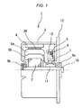
- Fig. 1 is a cross-sectional view of the DC commutator motor, observed from a side thereof, according to an embodiment of the present invention.
- a DC commutator motor 1 includes a yoke 3, a front bracket 12, a field magnet 4, and an armature 30 (a rotor).
- the yoke 3 is substantially cylindrical and includes an output-shaft-opposite-side bearing 6b. As illustrated in Fig. 1 , the output-shaft-opposite-side bearing 6b is positioned at a middle of an end face of the yoke 3 and rotatably supports one end of a shaft 10.
- the front bracket 12 is substantially disk-shaped and includes a brush holder 13 and an output-shaft-side bearing 6a.
- the front bracket 12 is positioned at an end of the yoke 3.
- the brush holder 13 retains a brush 8.
- a brush spring 9 is positioned between the brush holder 13 and the brush 8.
- the brush 8 is urged toward a commutator segment 7 by an elastic force of the brush.spring 9 (an elastic body) to slide in contact with the commutator segment 7. This allows the brush 8 to supply electric power, supplied from the outside, through the commutator segment 7 to an upper coil 5a and a lower coil 5b to be described hereinafter.
- the output-shaft-side bearing 6a is positioned at a center of the front bracket 12 and rotatably supports another end of the shaft 10.
- the field magnet 4 (a stator) is positioned on an inner peripheral surface of the yoke 3 and generates a magnetic field.
- the armature 30 is substantially cylindrical and includes an armature core 2, the upper coil 5a, the lower coil 5b, the commutator segment 7, and the shaft 10.
- the armature core 2 is formed by laminating substantially disk-shaped thin steel plates.
- the shaft 10 is positioned on a central axis of the armature 30 and is rotatably supported by the output-shaft-side bearing 6a and the output-shaft-opposite-side bearing 6b.
- the external diameter of the armature 30 is smaller than the inner diameter of the field magnet. This allows the armature 30 to be rotatably supported at an inner peripheral side of the field magnet 4 with a gap therebetween.
- the commutator segment 7 is positioned at a portion of the shaft 10 and supplies the electric power, supplied from the outside, to the upper coil 5a and the lower coil 5b.
- a configuration of the commutator segment 7 will be described in detail hereinafter with reference to Figs. 3 and 4 .
- the commutator segment 7 and the shaft 10 are fixed with each other by using a phenolic resin 11.
- the upper coil 5a is positioned at an outer peripheral side of the armature core 2 (at an upper side of Fig. 1 ).
- the lower coil 5b is positioned at an inner peripheral side of the armature core 2 (at a lower side of Fig. 1 ).
- Fig. 2 is a cross-sectional view of the DC commutator motor, illustrated in Fig. 1 , observed from the axial direction. Note that like reference characters indicate similar parts in Fig. 1 .
- the upper coils 5a are illustrated with solid lines, and the lower coils 5b with broken lines. Note that not all the coils are illustrated with the solid lines or the broken lines to facilitate viewing.
- Armature teeth 20 are formed (positioned) at equal intervals on an outer periphery of the armature core 2.
- An armature slot 21 is formed between two neighboring armature teeth 20.
- the armature slots 21 are formed (positioned) at equal intervals on the outer periphery of the armature core 2.
- the armature core 2 has 17 armature teeth 20 and 17 armature slots 21.
- Six field magnets 4 are positioned at equal intervals in a circumferential direction of the inner peripheral surface of the yoke 3.
- the upper coil 5a is positioned at an opening side (an upper layer side) of the armature slot 21.
- the lower coil 5b is positioned at a bottom side (a lower layer side) of the armature slot 21.
- Two coil segments 51a of the upper coils 5a and two coil segments 51b of the lower coils 5b are present in one armature slot 21.
- Seventeen commutator segments 7 are positioned at equal intervals in a circumferential direction of the shaft 10.
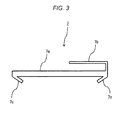
- Fig. 3 is a cross-sectional view of the commutator segment 7.
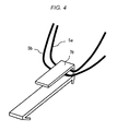
- Fig. 4 is a diagram for describing a use condition of the commutator segment 7.
- the commutator segment 7 is made of metal (a conductive member) and includes a sliding contact portion 7a, a hook portion 7b in a hook shape, and an anchor portion 7c as illustrated in Fig. 3 .
- the sliding contact portion 7a slides in contact with the brush 8.
- the anchor portion 7c functions as an anchor to the phenolic resin 11 to fix the commutator segment 7.
- the hook portion 7b can hook winding conductors of the upper coil 5a and the lower coil 5b as illustrated in Fig. 4 .
- the winding conductors are hooked as described above and then welded so that the winding conductors of the upper coil 5a and the lower coil 5b are fixed to the hook portion 7b of the commutator segment 7.
- the process for winding the upper coils 5a and the lower coils 5b can be divided into a first winding process and a second winding process.
- the first winding process is for winding all the lower coils 5b sequentially.
- the second winding process is for winding all the upper coils 5a sequentially.
- the second winding process is performed after the first winding process is finished, because the upper coil 5a is positioned at the opening side of the armature slot 21 and the lower coil 5b is positioned at the bottom side of the armature slot 21.
- An end of one continuous winding conductor (represented by a thick broken line in Fig. 2 ) is hooked to the hook portion 7b of a first commutator segment 7. Another end of the winding conductor is inserted into a first armature slot 21 at its bottom side. The winding conductor is then wound through the first armature slot 21 and a fourth armature slot 21 at its bottom side the number of turns Nb. The fourth armature slot 21 is located apart from the first armature slot 21 with two armature slots 21 therebetween. The winding conductor is then hooked to the hook portion 7b of a seventh commutator segment 7. A first lower coil 5b is wound as described above.
- the winding conductor is then inserted into a seventh armature slot 21 at its bottom side.
- the winding conductor is then wound through the seventh armature slot 21 and a 10th armature slot 21 at its bottom side the number of turns Nb.
- the 10th armature slot 21 is located apart from the seventh armature slot 21 with two armature slots 21 therebetween.
- the winding conductor is then hooked to the hook portion 7b of a 13th commutator segment 7.
- a second lower coil 5b is wound as described above.
- the winding conductor is further inserted into a 13th armature slot 21 at its bottom side.
- the winding conductor is then wound through the 13th armature slot 21 and a 16th armature slot 21 at its bottom side the number of turns Nb.
- the 16th armature slot 21 is located apart from the 13th armature slot 21 with two armature slots 21 therebetween.
- the winding conductor is then hooked to the hook portion 7b of a second commutator segment 7.
- a third lower coil 5b is wound as described above.
- the winding conductor (represented by a thin broken line in Fig. 2 ) is then inserted into a second armature slot 21 at its bottom side.
- the winding conductor is wound through the second armature slot 21 and a fifth armature slot 21 at its bottom side the number of turns Nb.
- the fifth armature slot 21 is located apart from the second armature slot 21 with two armature slots 21 therebetween.
- the winding conductor is then hooked to the hook portion 7b of an eighth commutator segment 7.
- a fourth lower coil 5b is wound as described above.
- the winding conductor is then inserted into an eighth armature slot 21 at its bottom side.
- the winding conductor is wound through the eighth armature slot 21 and an 11th armature slot 21 at its bottom side the number of turns Nb.
- the 11th armature slot 21 is located apart from the eighth armature slot 21 with two armature slots 21 therebetween.
- the winding conductor is then hooked to the hook portion 7b of a 14th commutator segment 7.
- a fifth lower coil 5b is wound as described above.
- the winding conductor is further inserted into a 14th armature slot 21 at its bottom side.
- the winding conductor is wound through the 14th armature slot 21 and a 17th armature slot 21 at its bottom side the number of turns Nb.
- the 17th armature slot 21 is located apart from the 14th armature slot 21 with two armature slots 21 therebetween.
- the winding conductor is then hooked to the hook portion 7b of a third commutator segment 7.
- a sixth lower coil 5b is wound as described above.
- the lower coils 5b will be further wound in a similar manner.
- the winding conductor passes through the commutator segments with the ordinal numbers of 1, 7, 13, 2, 8, 14, 3, 9, 15, 4, 10, 16, 5, 11, 17, 6, 12, and 1 in the sequence set forth.
- an end point of the winding of all the lower coils 5b is hooked to the hook portion 7b of the first commutator segment 7.
- the end point of the winding of all the lower coils 5b will be a start point of the winding of the upper coils 5a.
- the winding conductor (represented by a thick solid line in Fig. 2 ), which has been finally hooked to the hook portion 7b of the first commutator segment 7 in the first winding process, is inserted into the first armature slot 21 at its opening side.
- the winding conductor is then wound through the first armature slot 21 and the fourth armature slot 21 at its opening side the number of turns Na (where Na ⁇ Nb).
- the fourth armature slot 21 is located apart from the first armature slot 21 with two armature slots 21 therebetween.
- the winding conductor is then hooked to the hook portion 7b of the seventh commutator segment 7.
- a first upper coil 5a is wound as described above.
- the winding conductor is then inserted into the seventh armature slot 21 at its opening side.
- the winding conductor is wound through the seventh armature slot 21 and the 10th armature slot 21 at its opening side the number of turns Na.
- the 10th armature slot 21 is located apart from the seventh armature slot 21 with two armature slots 21 therebetween.
- the winding conductor is then hooked to the hook portion 7b of the 13th commutator segment 7.
- a second upper coil 5a is wound as described above.
- the winding conductor is further inserted into the 13th armature slot 21 at its opening side.
- the winding conductor is wound through the 13th armature slot 21 and the 16th armature slot 21 at its opening side the number of turns Na.
- the 16th armature slot 21 is located apart from the 13th armature slot 21 with two armature slots 21 therebetween.
- the winding conductor is then hooked to the hook portion 7b of the second commutator segment 7.
- a third upper coil 5a is wound as described above.
- the upper coils 5a will be further wound in a similar manner.
- the winding conductor passes through the commutator segments with the ordinal numbers of 1, 7, 13, 2, 8, 14, 3, 9, 15, 4, 10, 16, 5, 11, 17, 6, 12, and 1 in the sequence set forth.
- an end point of the winding of all the upper coils 5a is hooked to the hook portion 7b of the first commutator segment 7.
- the winding conductor of the upper coils 5a and the lower coils 5b which has been hooked to the hook portions 7b of the commutator segments 7, is then welded to be fixed to the hook portions 7b of the commutator segments 7.
- an increased winding tension can be set because the winding conductor is hooked to the hook portions 7b during the winding.
- one continuous winding conductor constitutes all the upper coils 5a and all the lower coils 5b.
- all the upper coils 5a and all the lower coils 5b are wound in a manner as if a line is continuously extended from one end to another end. This allows all the upper coils 5a and all the lower coils 5b to be wound in one operation with ease.
- the winding conductor of the upper coils 5a has an identical wire diameter to the winding conductor of the lower coils 5b.
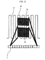
- Fig. 5 is a schematic view of the upper coil 5a and the lower coil 5b observed from the axial direction of the armature 30.
- seven armature teeth 20, six armature slots 21, and seven commutator segments 7 are illustrated in Fig. 5 .
- FIG. 2 A winding arrangement of the DC commutator motor 1 configured as described above will now be described with reference to Figs. 2 and 6 .
- two coil segments 51a of the upper coils 5a and two coil segments 51b of the upper coils 5b are present in one armature slot 21.
- 4 coil segments 51 are present in one armature slot 21.
- 68 coil segments 51 (4 coil segments ⁇ 17 slots) are present in the entire' armature 30.
- Fig. 6 is a winding connection diagram for describing a winding arrangement of the DC commutator motor 1 illustrated in Fig. 2 .
- the upper coils 5a are represented by solid lines
- the lower coils 5b are represented by broken lines.
- 17 armature teeth 20, 17 armature slots 21, 17 commutator segments 7, and two brushes 8 are illustrated.
- the winding conductors of two upper coils 5a and the winding conductors of two lower coils 5b are connected to one commutator segment 7.
- four winding conductors are connected to one commutator segment 7.
- Fig. 7 is a circuit diagram of a circuit including the first to third upper coils 5a and lower coils 5b. Note that, in Fig. 7 , an i-th commutator segment 7 is represented by reference characters 7 (No. i). This circuit includes three upper coils 5a and three lower coils 5b. That is, this circuit includes six coils in total. The first upper coil 5a and the first lower coil 5b are electrically connected in parallel to the first commutator segment 7 and the seventh commutator segment 7.
- the second upper coil 5a and the second lower coil 5b are electrically connected in parallel to the seventh commutator segment 7 and the 13th commutator segment 7.
- the third upper coil 5a and the third lower coil 5b are electrically connected in parallel to the 13th commutator segment 7 and the second commutator segment 7.
- inductance values of the upper coil 5a and the lower coil 5b are represented by L1 and L2, respectively.
- Resistance values of the upper coil 5a and the lower coil 5b are represented by R1 and R2, respectively.
- a combined inductance value and a combined resistance value of the upper coil 5a and the lower coil 5b are represented by Lp and Rp, respectively.
- Ease with which magnetic flux can pass varies in a manner dependent on the positions of the coils arranged in relation to the armature slot 21, a material of the armature core 2, the shape of the armature slots 21, and the like.
- the upper coil 5a is positioned at the opening side of the armature slot 21, and the lower coil 5b is positioned at the bottom side of the armature slot 21.
- the ease with which the magnetic flux can pass through the lower coil 5b is greater than the ease with which the magnetic flux can pass through the upper coil 5a with respect to the armature core 2.
- the inductance value L2 of the lower coil 5b is greater than the inductance value L1 of the upper coil 5a.
- the resistance values of the coils are determined by their circumferences, if the winding conductors have an identical wire diameter. In other words, the resistance values of the coils are determined by the lengths of the winding conductors that constitute the coils, if the winding conductors have an identical wire diameter.
- the upper coil 5a is located on the outer peripheral side of the armature 30 in comparison with the lower coil 5b. Thus, the crossover line of the upper coil 5a has a length longer than that of the crossover line of the lower coil 5b. If, therefore, the number of turns Na of the upper coil 5a is identical to the number of turns Nb of the lower coil 5b, a resistance value R1 of the upper coil 5a is higher than a resistance value R2 of the lower coil 5b.
- the resistance value of the upper coil 5a increases with respect to the resistance value of the lower coil 5b at a ratio dependent on a ratio between the external diameter of the armature 30 and the axial dimension of the armature 30.
- the resistance value of the upper coil 5a increases at a high ratio with respect to the resistance value of the lower coil 5b. This is because, in the case of a low-profile armature 30, the crossover lines of the winding conductor bring about a significant effect on the resistance values of the coils.
- the resistance value of the upper coil 5a increases at a low ratio with respect to the resistance value of the lower coil 5b. This is because the crossover lines of the winding conductor bring about a less significant effect on the resistance values of the coils, contrarily to the case of the armature 30 with a low profile.
- Fig. 8 is a table of the inductance values L1 and L2, the combined inductance value Lp, the resistance values R1 and R2, and the combined resistance value Rp, when the number of turns Na of the upper coil 5a and the number of turns Nb of the lower coil 5b are varied under a condition that the sum of the numbers of turns of the upper coil and the lower coil is maintained at 20 (constant).
- Five cases have been studied with the following conditions of the number of turns of the upper coil 5a and the number of turns of the lower coil 5b: (12 turns/8 turns), (11 turns/9 turns), (10 turns/10 turns), (9 turns/11 turns), and (8 turns/12 turns), as (the number of turns of the upper coil 5a/the number of turns of the lower coil 5b).
- Fig. 9 is a graph of the inductance values L1 and L2 and the combined inductance value Lp illustrated in Fig. 8 .
- Fig. 10 is a graph of the resistance values R1 and R2 and the combined resistance value Rp illustrated in Fig. 8 .
- the combined inductance value of the upper coil 5a and the lower coil 5b decreases as the number of turns Nb of the lower coil 5b increases.
- the inductance value L1 of the upper coil 5a decreases as the number of turns Na of the upper coil 5a decreases.
- the inductance value L2 of the lower coil 5b increases as the number of turns Nb of the lower coil 5b increases.
- the resistance value R1 of the upper coil 5a is identical to the resistance value R2 of the lower coil 5b, when the number of turns Na of the upper coil 5a is 9 and the number of turns Nb of the lower coil 5b is 11. Note that the resistance value R1 of the upper coil 5a decreases as the number of turns Na of the upper coil 5a decreases.
- the resistance value R2 of the lower coil 5b increases as the number of turns Nb of the lower coil 5b increases.
- the resistance value R1 of the upper coil 5a is identical to the resistance value R2 of the lower coil 5b when the number of turns Na of the upper coil 5a is 9 and the number of turns Nb of the lower coil 5b is 11.
- the numbers of turns at which the resistance value R1 of the upper coil 5a is identical to the resistance value R2 of the lower coil 5b vary in a manner dependent on the shape of the armature 30.
- the resistance values of the coils are determined by the lengths of the winding conductors that constitute the coils, if the winding conductors have an identical wire diameter.
- the resistance value R1 of the upper coil 5a is identical to the resistance value R2 of the lower coil 5b.
- the resistance value R1 of the upper coil 5a may not be identical to the resistance value R2 of the lower coil 5b even if the number of turns Na of the upper coil 5a and the number of turns Nb of the lower coil 5b are adjusted.
- the number of turns Na of the upper coil 5a and the number of turns Nb of the lower coil 5b may be set such that the difference between the resistance value R1 of the upper coil 5a and the resistance value R2 of the lower coil 5b is a minimum.
- the resistance values of the coils are determined by the lengths of the winding conductors that constitute the coils, if the winding conductors have an identical wire diameter.
- the number of turns Na of the upper coil 5a and the number of turns Nb of the lower coil 5b are set such that the difference between the length of the winding conductor constituting the upper coil 5a and the length of the winding conductor constituting the lower coil 5b is a minimum, the difference between the resistance value R1 of the upper coil 5a and the resistance value R2 of the lower coil 5b is a minimum.
- the condition of 9 turns for the upper coil 5a and 11 turns for the lower coil 5b is effective for both the reduction of the combined inductance and the equalization of the resistances. This allows simultaneously the commutating ability to be improved and currents passing through parallel windings to be equalized, reducing the current value bias and Joule heating, thereby suppressing an increase in temperature of the motor.
- the reduction in the combined inductance reduces voltage (sparking voltage) applied to the commutator segment 7, resulting in an improved commutating ability of the DC commutator motor 1. Furthermore, by suppressing the increase in temperature of the motor, the reduction in the output power volume ratio of the DC commutator motor 1 can be suppressed. Thus, the DC commutator motor 1 can provide a good commutating ability and suppress the reduction in the output power volume ratio.
- the number of turns of the upper coil 5a may be reduced to provide a condition that enables a further reduction of the combined inductance, such as 8 turns of the upper coil 5a and 12 turns of the lower coil 5b, rather than the condition of 9 turns for the upper coil 5a and 11 turns for the lower coil 5b.
- the combined inductance of the upper coil 5a and the lower coil 5b is reduced according to the present embodiment.
- the resistance value of the upper coil and the resistance value of the lower coil are equalized, which eliminates the selective action, and, therefore, the increase in temperature of the motor can be suppressed.
- the reduction in the output power volume ratio of the DC commutator motor 1 can be suppressed.
- the DC commutator motor 1 can provide a good commutating ability and suppress the reduction in the output power volume ratio.
- one winding conductor is wound from the start point of winding to the end point of the winding while the winding conductor is hooked to the hook portions 7b of the commutator segments 7, and, therefore, a plurality of upper coils and a plurality of lower coils can be securely connected to the commutator segments.
- one winding conductor is wound from the start point of the winding to the end point of the winding while the winding conductor is hooked to the hook portions 7b of the commutator segments 7, and thus, the commutator segment 7 connecting the end point of the winding of the lower coils 5b coincides with the commutator segment 7 connecting the start point of the winding of the upper coils 5a. This coincidence, however, does not have to take place.
- the upper coils 5a are constituted by a first continuous winding conductor, while the lower coils 5b are constituted by a second continuous winding conductor.
- the first winding conductor and the second winding conductor are separate winding conductors. Note that the first winding conductor and the second winding conductor have an identical wire diameter.
- a commutator segment 7 is uniquely determined for connecting the end point of the winding of the lower coils 5b and for connecting the start point of the winding of the upper coils 5a.
- any position can be set as the start point of the winding of the upper coils 5a.
- the DC commutator motor 1 according to an embodiment of the present invention is mounted as a motor for driving a hydraulic pump of the automobile as an example.
- Fig. 11 is a schematic block diagram of the automobile provided with the DC commutator motor 1 according to the embodiment of the present invention.
- An automobile 50 has a configuration that is roughly divided into a drive system and a brake system.
- the drive system includes an engine ENG, a transmission TM, a differential DEF, a front drive shaft FDS, a front wheel FW, a rear drive shaft RDS, and a rear wheel RW.
- the brake system includes a brake pedal BP, a hydraulic pump OP (an automobile auxiliary machine), a reservoir R, an electronic control unit ECU, a brake actuator BA, and a brake caliper BC.
- an automobile auxiliary machine refers to a peripheral device for operating an engine.
- the hydraulic pump OP includes the DC commutator motor 1 as a motor for driving the hydraulic pump.
- brake information indicative of a depression angle of the brake pedal BP is input from the brake pedal BP to the electronic control unit ECU.
- the electronic control unit ECU controls an output of the DC commutator motor 1 mounted on the hydraulic pump OP.
- the hydraulic pump OP which is driven by the DC commutator motor 1, applies pressure to a hydraulic fluid supplied from the reservoir R under the control of the electronic control unit ECU.
- the brake actuator BA transmits the pressure applied by the hydraulic pump OP to the four brake calipers BC.
- the brake calipers BC are actuated by the pressure to apply the brake.
- the DC commutator motor 1 can be reduced in size while its output is maintained because the output power volume ratio of the DC commutator motor 1 is higher than that of a conventional DC commutator motor. This can contribute to a reduction in size of the automobile 50.
- the present invention is not limited to the embodiments described above, and various modifications are included in the present invention.
- the embodiments described above have been described in detail in order to facilitate understanding.
- the embodiments are not limited to those that include the entire configurations described above. It is possible to replace a part of a configuration of an embodiment with a configuration of another embodiment. It is also possible to add, to a configuration of an embodiment, a configuration of another embodiment. It is further possible to add another configuration to a part of a configuration of each embodiment, delete a part of a configuration of each embodiment, and replace a part of a configuration of each embodiment with another configuration.
- a part or all of the configurations, functions, processing units, and the like described above may be also achieved by hardware by designing an integrated circuit, for example.
- a 6-pole, 17-slot DC commutator motor with the wave winding has been described as an example.
- a winding scheme is not limited to the wave winding and any scheme may be used.
- the sum of the number of turns Na of the upper coil 5a and the number of turns Nb of the lower coil 5b is 20, but this sum may be any number.
- the DC commutator motor 1 is mounted on an automobile as a motor for driving a hydraulic pump, but the DC commutator motor 1 may be used for any application.
Landscapes
- Engineering & Computer Science (AREA)
- Power Engineering (AREA)
- Dc Machiner (AREA)
- Windings For Motors And Generators (AREA)
Abstract
Description
- The present invention relates to a DC commutator motor and an automobile including the same, and particularly, to a DC commutator motor including an upper coil and a lower coil connected in parallel as an armature winding, and an automobile including the same.
- DC commutator motors, with which high power can be obtained with ease, have been used as, for example, motors for driving hydraulic pumps for vehicles. In recent years, DC commutator motors have also started being used for auxiliary machines of an automobile besides hydraulic pumps in order to reduce fuel consumption of the automobile. The number of DC commutator motors mounted on an automobile is on the increase under such circumstances. To cope with this trend, a reduction in size and weight of a motor should be promoted while its output is maintained. Consequently, an output power volume ratio (a value obtained by dividing the output of a motor by the volume of the motor) demanded of a DC commutator motor to be mounted on an automobile is ever increasing.
- There is a DC commutator motor known for each coil constituted by one winding conductor wound in a wave winding (see, for example,
JP-2007-151268-A - Here, the maximum applied voltage of the DC commutator motor is the guaranteed voltage of a battery to be mounted on an automobile, and hence, the output power volume ratio is increased by increasing a current flowing through the DC commutator motor (use of high current). The use of the high current, however, leads to an elevated temperature of the DC commutator motor. Thus, an adequate diameter is selected for the winding conductor to keep the temperature elevation in an allowable range. Particularly, in order to cope with the use of the high current, the winding conductor is designed to have a diameter increased accordingly. Here, winding tension is increased so that the winding conductor fits securely in the inside of a slot provided in an armature.
- In the case with the DC commutator motor disclosed in
JP-2007-151268-A - To cope with this, at least two thin winding conductors are used in parallel, so that the winding performance of the winding conductor is improved while the area of the cross section of the winding conductor is increased. This, however, has posed a concern about a short circuit between the winding conductors, which are twisted. As a solution to this, a varnish treatment is provided for the purpose of fixing the coils and maintaining insulation performance. This, however, has increased man-hours for the motor assembly, resulting in a cost increase.
- Furthermore, ununiform resistance values of parallel armature coils cause a selective action, which leads to an excessive increase in temperature of the motor, resulting in a reduction in an output power volume ratio and efficiency of the motor.
- In addition, the DC commutator motor, disclosed in
JP-2007-151268-A - It is therefore an object of the present invention to provide a DC commutator motor that has a good commutating ability and can suppress a reduction in an output power volume ratio and to provide an automobile provided with the DC commutator motor.
- In order to attain the object described above, the present invention provides a DC commutator motor that includes: a yoke; a field magnet positioned at an inner peripheral side of the yoke; an armature rotatably supported at an inner peripheral side of the field magnet with a gap therebetween; a shaft positioned on a central axis of the armature; a plurality of commutator segments positioned in a circumferential direction of the shaft; a plurality of armature slots positioned on an outer periphery of the armature; an upper coil wound the number of turns Na through two of the armature slots at an opening side of each of the two slots, the two of the armature slots being located apart from each other with the predetermined number of armature slots therebetween; and/or a lower coil connected in parallel with the upper coil, the lower coil being wound the number of turns Nb through the two of the armature slots at a bottom side of each of the two slots, wherein the number of turns Na is smaller than the number of turns Nb.
- This reduces the combined inductance of the upper coil and the lower coil. The reduction in combined inductance reduces the voltage (sparking voltage) applied to the commutator segments, improving the commutating ability of the DC commutator motor.
- According to the present invention, a good commutating ability can be obtained and a reduction in an output power volume ratio can be suppressed.
-
-
Fig. 1 is a cross-sectional view of a DC commutator motor, observed from a side thereof, according to an embodiment of the present invention; -
Fig. 2 is a cross-sectional view of the DC commutator motor, illustrated inFig. 1 , observed from an axial direction; -
Fig. 3 is a cross-sectional view of a commutator segment for use in the DC commutator motor according to the embodiment of the present invention; -
Fig. 4 is a diagram for describing a use condition of the commutator segment for use in the DC commutator motor according to the embodiment of the present invention; -
Fig. 5 is a schematic view of an upper coil and a lower coil, observed from the axial direction of an armature, for use in the DC commutator motor according to the embodiment of the present invention; -
Fig. 6 is a winding connection diagram for describing a winding arrangement of the DC commutator motor illustrated inFig. 2 ; -
Fig. 7 is a circuit diagram of a circuit including first to third upper coils and lower coils for use in the DC commutator motor according to the embodiment of the present invention; -
Fig. 8 is a table of inductance values L1 and L2, a combined inductance value Lp, resistance values R1 and R2, and a combined resistance value Rp, when the number of turns of the upper coil and the number of turns of the lower coil are varied under a condition that the sum of the numbers of turns of the upper coil and the lower coil is maintained at 20; -
Fig. 9 is a graph of the inductance values L1 and L2 and the combined inductance value Lp illustrated inFig. 8 ; -
Fig. 10 is a graph of the resistance values R1 and R2 and the combined resistance value Rp illustrated inFig. 8 ; and -
Fig. 11 is a schematic block diagram of an automobile provided with a DC commutator motor according to an embodiment of the present invention. - Some embodiments of the present invention will be described with reference to
Figs. 1 to 10 . A DC commutator motor of the wave winding with 6 poles and 17 slots will be described below as an example. This DC commutator motor is used, for example, for a hydraulic pump in an automobile. - A configuration of a DC commutator motor will now be described with reference to
Figs. 1 and2 .Fig. 1 is a cross-sectional view of the DC commutator motor, observed from a side thereof, according to an embodiment of the present invention. - A
DC commutator motor 1 includes ayoke 3, afront bracket 12, afield magnet 4, and an armature 30 (a rotor). - The
yoke 3 is substantially cylindrical and includes an output-shaft-opposite-side bearing 6b. As illustrated inFig. 1 , the output-shaft-opposite-side bearing 6b is positioned at a middle of an end face of theyoke 3 and rotatably supports one end of ashaft 10. - The
front bracket 12 is substantially disk-shaped and includes abrush holder 13 and an output-shaft-side bearing 6a. Thefront bracket 12 is positioned at an end of theyoke 3. Thebrush holder 13 retains abrush 8. Abrush spring 9 is positioned between thebrush holder 13 and thebrush 8. Thebrush 8 is urged toward acommutator segment 7 by an elastic force of the brush.spring 9 (an elastic body) to slide in contact with thecommutator segment 7. This allows thebrush 8 to supply electric power, supplied from the outside, through thecommutator segment 7 to anupper coil 5a and alower coil 5b to be described hereinafter. The output-shaft-side bearing 6a is positioned at a center of thefront bracket 12 and rotatably supports another end of theshaft 10. - The field magnet 4 (a stator) is positioned on an inner peripheral surface of the
yoke 3 and generates a magnetic field. - The
armature 30 is substantially cylindrical and includes anarmature core 2, theupper coil 5a, thelower coil 5b, thecommutator segment 7, and theshaft 10. Thearmature core 2 is formed by laminating substantially disk-shaped thin steel plates. Theshaft 10 is positioned on a central axis of thearmature 30 and is rotatably supported by the output-shaft-side bearing 6a and the output-shaft-opposite-side bearing 6b. Here, the external diameter of thearmature 30 is smaller than the inner diameter of the field magnet. This allows thearmature 30 to be rotatably supported at an inner peripheral side of thefield magnet 4 with a gap therebetween. - The
commutator segment 7 is positioned at a portion of theshaft 10 and supplies the electric power, supplied from the outside, to theupper coil 5a and thelower coil 5b. A configuration of thecommutator segment 7 will be described in detail hereinafter with reference toFigs. 3 and4 . Here, thecommutator segment 7 and theshaft 10 are fixed with each other by using aphenolic resin 11. Theupper coil 5a is positioned at an outer peripheral side of the armature core 2 (at an upper side ofFig. 1 ). Thelower coil 5b is positioned at an inner peripheral side of the armature core 2 (at a lower side ofFig. 1 ). -
Fig. 2 is a cross-sectional view of the DC commutator motor, illustrated inFig. 1 , observed from the axial direction. Note that like reference characters indicate similar parts inFig. 1 . InFig. 2 , theupper coils 5a are illustrated with solid lines, and thelower coils 5b with broken lines. Note that not all the coils are illustrated with the solid lines or the broken lines to facilitate viewing. -
Armature teeth 20 are formed (positioned) at equal intervals on an outer periphery of thearmature core 2. Anarmature slot 21 is formed between two neighboringarmature teeth 20. In other words, thearmature slots 21 are formed (positioned) at equal intervals on the outer periphery of thearmature core 2. In the present embodiment, thearmature core 2 has 17armature teeth armature slots 21. - Six field magnets 4 (stators) are positioned at equal intervals in a circumferential direction of the inner peripheral surface of the
yoke 3. - The
upper coil 5a is positioned at an opening side (an upper layer side) of thearmature slot 21. Thelower coil 5b is positioned at a bottom side (a lower layer side) of thearmature slot 21. Twocoil segments 51a of theupper coils 5a and twocoil segments 51b of thelower coils 5b are present in onearmature slot 21. - Seventeen
commutator segments 7 are positioned at equal intervals in a circumferential direction of theshaft 10. - A configuration of the
commutator segment 7 will now be described in detail with reference toFigs. 3 and4 .Fig. 3 is a cross-sectional view of thecommutator segment 7.Fig. 4 is a diagram for describing a use condition of thecommutator segment 7. - The
commutator segment 7 is made of metal (a conductive member) and includes a slidingcontact portion 7a, ahook portion 7b in a hook shape, and ananchor portion 7c as illustrated inFig. 3 . The slidingcontact portion 7a slides in contact with thebrush 8. Theanchor portion 7c functions as an anchor to thephenolic resin 11 to fix thecommutator segment 7. Thehook portion 7b can hook winding conductors of theupper coil 5a and thelower coil 5b as illustrated inFig. 4 . The winding conductors are hooked as described above and then welded so that the winding conductors of theupper coil 5a and thelower coil 5b are fixed to thehook portion 7b of thecommutator segment 7. - A process for winding the
upper coils 5a and thelower coils 5b will now be described with reference toFig. 2 . The process for winding theupper coils 5a and thelower coils 5b can be divided into a first winding process and a second winding process. The first winding process is for winding all thelower coils 5b sequentially. The second winding process is for winding all theupper coils 5a sequentially. Here, the second winding process is performed after the first winding process is finished, because theupper coil 5a is positioned at the opening side of thearmature slot 21 and thelower coil 5b is positioned at the bottom side of thearmature slot 21. - An end of one continuous winding conductor (represented by a thick broken line in
Fig. 2 ) is hooked to thehook portion 7b of afirst commutator segment 7. Another end of the winding conductor is inserted into afirst armature slot 21 at its bottom side. The winding conductor is then wound through thefirst armature slot 21 and afourth armature slot 21 at its bottom side the number of turns Nb. Thefourth armature slot 21 is located apart from thefirst armature slot 21 with twoarmature slots 21 therebetween. The winding conductor is then hooked to thehook portion 7b of aseventh commutator segment 7. A firstlower coil 5b is wound as described above. - The winding conductor is then inserted into a
seventh armature slot 21 at its bottom side. The winding conductor is then wound through theseventh armature slot 21 and a10th armature slot 21 at its bottom side the number of turns Nb. The10th armature slot 21 is located apart from theseventh armature slot 21 with twoarmature slots 21 therebetween. The winding conductor is then hooked to thehook portion 7b of a13th commutator segment 7. A secondlower coil 5b is wound as described above. - The winding conductor is further inserted into a
13th armature slot 21 at its bottom side. The winding conductor is then wound through the13th armature slot 21 and a16th armature slot 21 at its bottom side the number of turns Nb. The16th armature slot 21 is located apart from the13th armature slot 21 with twoarmature slots 21 therebetween. The winding conductor is then hooked to thehook portion 7b of asecond commutator segment 7. A thirdlower coil 5b is wound as described above. - The winding conductor (represented by a thin broken line in
Fig. 2 ) is then inserted into asecond armature slot 21 at its bottom side. The winding conductor is wound through thesecond armature slot 21 and afifth armature slot 21 at its bottom side the number of turns Nb. Thefifth armature slot 21 is located apart from thesecond armature slot 21 with twoarmature slots 21 therebetween. The winding conductor is then hooked to thehook portion 7b of aneighth commutator segment 7. A fourthlower coil 5b is wound as described above. - The winding conductor is then inserted into an
eighth armature slot 21 at its bottom side. The winding conductor is wound through theeighth armature slot 21 and an11th armature slot 21 at its bottom side the number of turns Nb. The11th armature slot 21 is located apart from theeighth armature slot 21 with twoarmature slots 21 therebetween. The winding conductor is then hooked to thehook portion 7b of a14th commutator segment 7. A fifthlower coil 5b is wound as described above. - The winding conductor is further inserted into a
14th armature slot 21 at its bottom side. The winding conductor is wound through the14th armature slot 21 and a17th armature slot 21 at its bottom side the number of turns Nb. The17th armature slot 21 is located apart from the14th armature slot 21 with twoarmature slots 21 therebetween. The winding conductor is then hooked to thehook portion 7b of athird commutator segment 7. A sixthlower coil 5b is wound as described above. - The
lower coils 5b will be further wound in a similar manner. In the first winding process, the winding conductor passes through the commutator segments with the ordinal numbers of 1, 7, 13, 2, 8, 14, 3, 9, 15, 4, 10, 16, 5, 11, 17, 6, 12, and 1 in the sequence set forth. Hence, an end point of the winding of all thelower coils 5b is hooked to thehook portion 7b of thefirst commutator segment 7. - The end point of the winding of all the
lower coils 5b will be a start point of the winding of theupper coils 5a. The winding conductor (represented by a thick solid line inFig. 2 ), which has been finally hooked to thehook portion 7b of thefirst commutator segment 7 in the first winding process, is inserted into thefirst armature slot 21 at its opening side. The winding conductor is then wound through thefirst armature slot 21 and thefourth armature slot 21 at its opening side the number of turns Na (where Na < Nb). Thefourth armature slot 21 is located apart from thefirst armature slot 21 with twoarmature slots 21 therebetween. The winding conductor is then hooked to thehook portion 7b of theseventh commutator segment 7. A firstupper coil 5a is wound as described above. - The winding conductor is then inserted into the
seventh armature slot 21 at its opening side. The winding conductor is wound through theseventh armature slot 21 and the10th armature slot 21 at its opening side the number of turns Na. The10th armature slot 21 is located apart from theseventh armature slot 21 with twoarmature slots 21 therebetween. The winding conductor is then hooked to thehook portion 7b of the13th commutator segment 7. A secondupper coil 5a is wound as described above. - The winding conductor is further inserted into the
13th armature slot 21 at its opening side. The winding conductor is wound through the13th armature slot 21 and the16th armature slot 21 at its opening side the number of turns Na. The16th armature slot 21 is located apart from the13th armature slot 21 with twoarmature slots 21 therebetween. The winding conductor is then hooked to thehook portion 7b of thesecond commutator segment 7. A thirdupper coil 5a is wound as described above. - The
upper coils 5a will be further wound in a similar manner. In the second winding process, the winding conductor passes through the commutator segments with the ordinal numbers of 1, 7, 13, 2, 8, 14, 3, 9, 15, 4, 10, 16, 5, 11, 17, 6, 12, and 1 in the sequence set forth. Hence, an end point of the winding of all theupper coils 5a is hooked to thehook portion 7b of thefirst commutator segment 7. - When the first and second winding processes have been performed, the winding conductor of the
upper coils 5a and thelower coils 5b, which has been hooked to thehook portions 7b of thecommutator segments 7, is then welded to be fixed to thehook portions 7b of thecommutator segments 7. This securely connects all theupper coils 5a and all thelower coils 5b to thecommutator segments 7. In addition, an increased winding tension can be set because the winding conductor is hooked to thehook portions 7b during the winding. - In the present embodiment, one continuous winding conductor constitutes all the
upper coils 5a and all thelower coils 5b. In other words, all theupper coils 5a and all thelower coils 5b are wound in a manner as if a line is continuously extended from one end to another end. This allows all theupper coils 5a and all thelower coils 5b to be wound in one operation with ease. Note that, in the present embodiment, the winding conductor of theupper coils 5a has an identical wire diameter to the winding conductor of thelower coils 5b. -
Fig. 5 is a schematic view of theupper coil 5a and thelower coil 5b observed from the axial direction of thearmature 30. For simplicity of the description, sevenarmature teeth 20, sixarmature slots 21, and sevencommutator segments 7 are illustrated inFig. 5 . In this example, anupper coil 5a with the number of turns Na = 9 and alower coil 5b with the number of turns Nb = 11 are connected in parallel to thefirst commutator segment 7 and theseventh commutator segment 7. - A winding arrangement of the
DC commutator motor 1 configured as described above will now be described with reference toFigs. 2 and6 . As illustrated inFig. 2 , twocoil segments 51a of theupper coils 5a and twocoil segments 51b of theupper coils 5b are present in onearmature slot 21. In total, 4 coil segments 51 are present in onearmature slot 21. Hence, 68 coil segments 51 (4 coil segments × 17 slots) are present in the entire'armature 30. -
Fig. 6 is a winding connection diagram for describing a winding arrangement of theDC commutator motor 1 illustrated inFig. 2 . InFig. 6 , theupper coils 5a are represented by solid lines, and thelower coils 5b are represented by broken lines. Note that, inFig. 6 , 17armature teeth armature slots commutator segments 7, and two brushes 8 (an anode and a cathode) are illustrated. The winding conductors of twoupper coils 5a and the winding conductors of twolower coils 5b are connected to onecommutator segment 7. Thus, in total, four winding conductors are connected to onecommutator segment 7. - An operation of the DC commutator motor according to the embodiment of the present invention will now be described with reference to
Fig. 2 . When voltage is applied to the brushes 8 (not illustrated inFig. 2 ), current passes through thecommutator segments 7 that slide in contact with thebrushes 8. The current then passes through theupper coils 5a and thelower coils 5b connected to thecommutator segments 7. This allows the magnetic field generated by thefield magnets 4 and a magnetic field generated by theupper coils 5a and thelower coils 5b to interact with each other to generate a continuous rotational torque, resulting in a mechanical output. - An operational advantage of the
DC commutator motor 1 according to the embodiment of the present invention will now be described with reference toFigs. 7 to 10 .Fig. 7 is a circuit diagram of a circuit including the first to thirdupper coils 5a andlower coils 5b. Note that, inFig. 7 , an i-th commutator segment 7 is represented by reference characters 7 (No. i). This circuit includes threeupper coils 5a and threelower coils 5b. That is, this circuit includes six coils in total. The firstupper coil 5a and the firstlower coil 5b are electrically connected in parallel to thefirst commutator segment 7 and theseventh commutator segment 7. The secondupper coil 5a and the secondlower coil 5b are electrically connected in parallel to theseventh commutator segment 7 and the13th commutator segment 7. The thirdupper coil 5a and the thirdlower coil 5b are electrically connected in parallel to the13th commutator segment 7 and thesecond commutator segment 7. - For simplicity of the description, the first
upper coil 5a and the firstlower coil 5b, connected in parallel, will be described. Here, inductance values of theupper coil 5a and thelower coil 5b are represented by L1 and L2, respectively. Resistance values of theupper coil 5a and thelower coil 5b are represented by R1 and R2, respectively. A combined inductance value and a combined resistance value of theupper coil 5a and thelower coil 5b are represented by Lp and Rp, respectively. - Ease with which magnetic flux can pass varies in a manner dependent on the positions of the coils arranged in relation to the
armature slot 21, a material of thearmature core 2, the shape of thearmature slots 21, and the like. In the present embodiment, theupper coil 5a is positioned at the opening side of thearmature slot 21, and thelower coil 5b is positioned at the bottom side of thearmature slot 21. Hence, the ease with which the magnetic flux can pass through thelower coil 5b is greater than the ease with which the magnetic flux can pass through theupper coil 5a with respect to thearmature core 2. Thus, if the number of turns Na of theupper coil 5a is identical to the number of turns Nb of thelower coil 5b, the inductance value L2 of thelower coil 5b is greater than the inductance value L1 of theupper coil 5a. - The resistance values of the coils are determined by their circumferences, if the winding conductors have an identical wire diameter. In other words, the resistance values of the coils are determined by the lengths of the winding conductors that constitute the coils, if the winding conductors have an identical wire diameter. In the present embodiment, the
upper coil 5a is located on the outer peripheral side of thearmature 30 in comparison with thelower coil 5b. Thus, the crossover line of theupper coil 5a has a length longer than that of the crossover line of thelower coil 5b. If, therefore, the number of turns Na of theupper coil 5a is identical to the number of turns Nb of thelower coil 5b, a resistance value R1 of theupper coil 5a is higher than a resistance value R2 of thelower coil 5b. - The resistance value of the
upper coil 5a increases with respect to the resistance value of thelower coil 5b at a ratio dependent on a ratio between the external diameter of thearmature 30 and the axial dimension of thearmature 30. - If the external diameter of the
armature 30 is larger than the axial dimension of thearmature 30, or in other words, if thearmature 30 has a low profile, the resistance value of theupper coil 5a increases at a high ratio with respect to the resistance value of thelower coil 5b. This is because, in the case of a low-profile armature 30, the crossover lines of the winding conductor bring about a significant effect on the resistance values of the coils. - Conversely, if the external diameter of the
armature 30 is smaller than the axial dimension of thearmature 30, or in other words, if thearmature 30 has a high profile, the resistance value of theupper coil 5a increases at a low ratio with respect to the resistance value of thelower coil 5b. This is because the crossover lines of the winding conductor bring about a less significant effect on the resistance values of the coils, contrarily to the case of thearmature 30 with a low profile. - The resistance values and the inductance values of the
upper coil 5a and thelower coil 5b will now be described with reference toFigs. 8 to 10 . -
Fig. 8 is a table of the inductance values L1 and L2, the combined inductance value Lp, the resistance values R1 and R2, and the combined resistance value Rp, when the number of turns Na of theupper coil 5a and the number of turns Nb of thelower coil 5b are varied under a condition that the sum of the numbers of turns of the upper coil and the lower coil is maintained at 20 (constant). Five cases have been studied with the following conditions of the number of turns of theupper coil 5a and the number of turns of thelower coil 5b: (12 turns/8 turns), (11 turns/9 turns), (10 turns/10 turns), (9 turns/11 turns), and (8 turns/12 turns), as (the number of turns of theupper coil 5a/the number of turns of thelower coil 5b). -
Fig. 9 is a graph of the inductance values L1 and L2 and the combined inductance value Lp illustrated inFig. 8 .Fig. 10 is a graph of the resistance values R1 and R2 and the combined resistance value Rp illustrated inFig. 8 . As illustrated inFig. 9 , under the condition that the sum of the number of turns Na of theupper coil 5a and the number of turns Nb of thelower coil 5b is 20, the combined inductance value of theupper coil 5a and thelower coil 5b decreases as the number of turns Nb of thelower coil 5b increases. Note that the inductance value L1 of theupper coil 5a decreases as the number of turns Na of theupper coil 5a decreases. The inductance value L2 of thelower coil 5b increases as the number of turns Nb of thelower coil 5b increases. - As illustrated in
Fig. 10 , under the condition that the sum of the number of turns Na of theupper coil 5a and the number of turns Nb of thelower coil 5b is 20, the resistance value R1 of theupper coil 5a is identical to the resistance value R2 of thelower coil 5b, when the number of turns Na of theupper coil 5a is 9 and the number of turns Nb of thelower coil 5b is 11. Note that the resistance value R1 of theupper coil 5a decreases as the number of turns Na of theupper coil 5a decreases. The resistance value R2 of thelower coil 5b increases as the number of turns Nb of thelower coil 5b increases. - In the present embodiment, the resistance value R1 of the
upper coil 5a is identical to the resistance value R2 of thelower coil 5b when the number of turns Na of theupper coil 5a is 9 and the number of turns Nb of thelower coil 5b is 11. The numbers of turns at which the resistance value R1 of theupper coil 5a is identical to the resistance value R2 of thelower coil 5b, however, vary in a manner dependent on the shape of thearmature 30. As described above, the resistance values of the coils are determined by the lengths of the winding conductors that constitute the coils, if the winding conductors have an identical wire diameter. Hence, when the number of turns Na of theupper coil 5a and the number of turns Nb of thelower coil 5b are set such that the winding conductor constituting theupper coil 5a and the winding conductor constituting thelower coil 5b have an identical length, the resistance value R1 of theupper coil 5a is identical to the resistance value R2 of thelower coil 5b. - In some cases dependent on the shape of the
armature 30, however, the resistance value R1 of theupper coil 5a may not be identical to the resistance value R2 of thelower coil 5b even if the number of turns Na of theupper coil 5a and the number of turns Nb of thelower coil 5b are adjusted. In this case, the number of turns Na of theupper coil 5a and the number of turns Nb of thelower coil 5b may be set such that the difference between the resistance value R1 of theupper coil 5a and the resistance value R2 of thelower coil 5b is a minimum. Specifically, as described above, the resistance values of the coils are determined by the lengths of the winding conductors that constitute the coils, if the winding conductors have an identical wire diameter. Hence, when the number of turns Na of theupper coil 5a and the number of turns Nb of thelower coil 5b are set such that the difference between the length of the winding conductor constituting theupper coil 5a and the length of the winding conductor constituting thelower coil 5b is a minimum, the difference between the resistance value R1 of theupper coil 5a and the resistance value R2 of thelower coil 5b is a minimum. - With the
DC commutator motor 1 according to the present embodiment, the condition of 9 turns for theupper coil lower coil 5b is effective for both the reduction of the combined inductance and the equalization of the resistances. This allows simultaneously the commutating ability to be improved and currents passing through parallel windings to be equalized, reducing the current value bias and Joule heating, thereby suppressing an increase in temperature of the motor. - In other words, the reduction in the combined inductance reduces voltage (sparking voltage) applied to the
commutator segment 7, resulting in an improved commutating ability of theDC commutator motor 1. Furthermore, by suppressing the increase in temperature of the motor, the reduction in the output power volume ratio of theDC commutator motor 1 can be suppressed. Thus, theDC commutator motor 1 can provide a good commutating ability and suppress the reduction in the output power volume ratio. - In order to place a priority on the improvement of the commutation ability, the number of turns of the
upper coil 5a may be reduced to provide a condition that enables a further reduction of the combined inductance, such as 8 turns of theupper coil lower coil 5b, rather than the condition of 9 turns for theupper coil lower coil 5b. - As described above, the combined inductance of the
upper coil 5a and thelower coil 5b is reduced according to the present embodiment. This reduces voltage (sparking voltage) applied to thecommutator segment 7, resulting in an improved commutating ability of theDC commutator motor 1. Furthermore, the resistance value of the upper coil and the resistance value of the lower coil are equalized, which eliminates the selective action, and, therefore, the increase in temperature of the motor can be suppressed. Hence, the reduction in the output power volume ratio of theDC commutator motor 1 can be suppressed. Thus, theDC commutator motor 1 can provide a good commutating ability and suppress the reduction in the output power volume ratio. In addition, one winding conductor is wound from the start point of winding to the end point of the winding while the winding conductor is hooked to thehook portions 7b of thecommutator segments 7, and, therefore, a plurality of upper coils and a plurality of lower coils can be securely connected to the commutator segments. - In the embodiment described above, one winding conductor is wound from the start point of the winding to the end point of the winding while the winding conductor is hooked to the
hook portions 7b of thecommutator segments 7, and thus, thecommutator segment 7 connecting the end point of the winding of thelower coils 5b coincides with thecommutator segment 7 connecting the start point of the winding of theupper coils 5a. This coincidence, however, does not have to take place. - In the present modified embodiment, the
upper coils 5a are constituted by a first continuous winding conductor, while thelower coils 5b are constituted by a second continuous winding conductor. Here, the first winding conductor and the second winding conductor are separate winding conductors. Note that the first winding conductor and the second winding conductor have an identical wire diameter. - If one winding conductor is wound in a manner as if a line is continuously extended from one end to another end, a
commutator segment 7 is uniquely determined for connecting the end point of the winding of thelower coils 5b and for connecting the start point of the winding of theupper coils 5a. Conversely, if one each winding conductor is used for theupper coils 5a and thelower coils 5b, any position can be set as the start point of the winding of theupper coils 5a. By adjusting the position of the start point of the winding of theupper coils 5a, an overlap of the crossover lines of theupper coils 5a and thelower coils 5b can be reduced in size. In addition, the plurality of upper coils and the plurality of lower coils can be each wound with ease. - An automobile will now be described, in which the
DC commutator motor 1 according to an embodiment of the present invention is mounted as a motor for driving a hydraulic pump of the automobile as an example. -
Fig. 11 is a schematic block diagram of the automobile provided with theDC commutator motor 1 according to the embodiment of the present invention. - An
automobile 50 has a configuration that is roughly divided into a drive system and a brake system. The drive system includes an engine ENG, a transmission TM, a differential DEF, a front drive shaft FDS, a front wheel FW, a rear drive shaft RDS, and a rear wheel RW. The brake system includes a brake pedal BP, a hydraulic pump OP (an automobile auxiliary machine), a reservoir R, an electronic control unit ECU, a brake actuator BA, and a brake caliper BC. Here, an automobile auxiliary machine refers to a peripheral device for operating an engine. - A description will be provided mainly on a structure and an operational advantage of the hydraulic pump OP, which is a characteristic part. The hydraulic pump OP includes the
DC commutator motor 1 as a motor for driving the hydraulic pump. When a driver of the automobile depresses the brake pedal, brake information indicative of a depression angle of the brake pedal BP is input from the brake pedal BP to the electronic control unit ECU. According to the brake information, the electronic control unit ECU controls an output of theDC commutator motor 1 mounted on the hydraulic pump OP. The hydraulic pump OP, which is driven by theDC commutator motor 1, applies pressure to a hydraulic fluid supplied from the reservoir R under the control of the electronic control unit ECU. The brake actuator BA transmits the pressure applied by the hydraulic pump OP to the four brake calipers BC. The brake calipers BC are actuated by the pressure to apply the brake. - The
DC commutator motor 1 can be reduced in size while its output is maintained because the output power volume ratio of theDC commutator motor 1 is higher than that of a conventional DC commutator motor. This can contribute to a reduction in size of theautomobile 50. - The present invention is not limited to the embodiments described above, and various modifications are included in the present invention. For example, the embodiments described above have been described in detail in order to facilitate understanding. The embodiments are not limited to those that include the entire configurations described above. It is possible to replace a part of a configuration of an embodiment with a configuration of another embodiment. It is also possible to add, to a configuration of an embodiment, a configuration of another embodiment. It is further possible to add another configuration to a part of a configuration of each embodiment, delete a part of a configuration of each embodiment, and replace a part of a configuration of each embodiment with another configuration. A part or all of the configurations, functions, processing units, and the like described above may be also achieved by hardware by designing an integrated circuit, for example.
- In the embodiments described above, a 6-pole, 17-slot DC commutator motor with the wave winding has been described as an example. The number of field magnets 4 (the number of poles) and the number of armature slots 21 (the number of slots), however, may be any number. A winding scheme is not limited to the wave winding and any scheme may be used.
- In the embodiments described above, the sum of the number of turns Na of the
upper coil 5a and the number of turns Nb of thelower coil 5b is 20, but this sum may be any number. - In the embodiment described above, the
DC commutator motor 1 is mounted on an automobile as a motor for driving a hydraulic pump, but theDC commutator motor 1 may be used for any application. - Features, components and specific details of the structures of the above-described embodiments may be exchanged or combined to form further embodiments optimized for the respective application. As far as those modifications are apparent for an expert skilled in the art they shall be disclosed implicitly by the above description without specifying explicitly every possible combination.
Claims (9)
- A DC commutator motor comprising:a yoke (3);a field magnet (4) positioned at an inner peripheral side of the yoke (3);an armature (30) rotatably supported at an inner peripheral side of the field magnet (4) with a gap therebetween;a shaft (10) positioned on a central axis of the armature;a plurality of commutator segments (7) positioned in a circumferential direction of the shaft (10);a plurality of armature slots (21) positioned on an outer periphery of the armature (30);an upper coil (5a) wound the number of turns Na through two of the armature slots (21) at an opening side of each of the two slots (21), the two of the armature slots (21) being located apart from each other with the predetermined number of armature slots (21) therebetween; anda lower coil (5b) connected in parallel with the upper coil (5a), the lower coil (5b) being wound the number of turns Nb through the two of the armature slots (21) at a bottom side of each of the two slots (21),wherein the number of turns Na is smaller than the number of turns Nb.
- The DC commutator motor according to claim 1, wherein
the number of turns Na of the upper coil (5a) and the number of turns Nb of the lower coil (5b) are set such that
a difference between a resistance value of the upper coil (5a) and a resistance value of the lower coil (5b) is a minimum. - The DC commutator motor according to claim 1 or 2, wherein
the number of turns Na of the upper coil (5a) and the number of turns Nb of the lower coil (5b) are set such that
the resistance value of the upper coil (5a) is identical to the resistance value of the lower coil (5b). - The DC commutator motor according to at least one of claims 1 to 3, wherein
an end point of winding of an i-th (where i = 1 to N) upper coil (5a) is connected to a start point of the winding of an (i + 1)th upper coil (5a), and
an end point of the winding of an i-th (where i = 1 to N) lower coil (5b) is connected to a start point of the winding of an (i + 1) lower coil (5b). - The DC commutator motor according to at least one of claims 1 to 4, wherein
the upper coil (5a) is constituted by a first continuous winding conductor, and
the lower coil (5b) is constituted by a second continuous winding conductor. - The DC commutator motor according to claim 4 or 5, wherein
each of the plurality of commutator segments (7) comprises a hook portion (7b), the hook portion (7b) comprising a conductive member in a hook shape,
the end point of the winding of the i-th upper coil is hooked to the hook portion (7b) of one of the commutator segments (7) to become the start point of the winding of the (i + 1)th upper coil, the one of the commutator segments (7) connecting the i-th upper coil and the (i + 1)th upper coil (5a), and
the end point of the winding of the i-th lower coil (5b) is hooked to the hook portion (7b) of one of the commutator segments (7) to become the start point of the winding of the (i + 1)th lower coil (5b), the one of the commutator segments (7) connecting the i-th lower coil and the (i + 1)th lower coil (5b). - The DC commutator motor according to claim 6, wherein
the first winding conductor and the second winding conductor are constituted by one continuous winding conductor. - The DC commutator motor according to at least one of claims 1 to 7, wherein
an external diameter of the armature (30) is larger than an axial dimension of the armature (30). - An automobile comprising
an auxiliary machine for use in the automobile (50), the auxiliary machine being a peripheral device for operating an engine (ENG),
the auxiliary machine comprising a DC commutator motor (1),
wherein the DC commutator motor (1) comprises:a yoke (3);a field magnet (4) positioned at an inner peripheral side of the yoke (3);an armature (30) rotatably supported at an inner peripheral side of the field magnet (4) with a gap therebetween;a shaft (10) positioned on a central axis of the armature (30);a plurality of commutator segments (7) positioned in a circumferential direction of the shaft (10);a plurality of armature slots (21) positioned on an outer periphery of the armature (30);an upper coil (5a) wound the number of turns Na through two of the armature slots (21) at an opening side of each of the two slots, the two of the armature slots (21) being located apart from each other with the predetermined number of armature slots (21) therebetween; anda lower coil (5b) connected in parallel with the upper coil (5a), the lower coil (5b) being wound the number of turns Nb through the two of the armature slots (21) at a bottom side of each of the two slots,wherein the number of turns Na is smaller than the number of turns Nb.
Applications Claiming Priority (1)
| Application Number | Priority Date | Filing Date | Title |
|---|---|---|---|
| JP2012089633A JP5890734B2 (en) | 2012-04-10 | 2012-04-10 | DC motor and vehicle equipped with the same |
Publications (3)
| Publication Number | Publication Date |
|---|---|
| EP2651018A2 true EP2651018A2 (en) | 2013-10-16 |
| EP2651018A3 EP2651018A3 (en) | 2017-08-30 |
| EP2651018B1 EP2651018B1 (en) | 2018-11-28 |
Family
ID=48013881
Family Applications (1)
| Application Number | Title | Priority Date | Filing Date |
|---|---|---|---|
| EP13162329.0A Not-in-force EP2651018B1 (en) | 2012-04-10 | 2013-04-04 | DC commutator motor and automobile including the same |
Country Status (4)
| Country | Link |
|---|---|
| US (1) | US9583985B2 (en) |
| EP (1) | EP2651018B1 (en) |
| JP (1) | JP5890734B2 (en) |
| CN (1) | CN103368348B (en) |
Families Citing this family (4)
| Publication number | Priority date | Publication date | Assignee | Title |
|---|---|---|---|---|
| JP6167049B2 (en) * | 2014-02-17 | 2017-07-19 | 日立オートモティブシステムズエンジニアリング株式会社 | Armature winding method |
| US11139722B2 (en) | 2018-03-02 | 2021-10-05 | Black & Decker Inc. | Motor having an external heat sink for a power tool |
| JP7314845B2 (en) * | 2020-03-24 | 2023-07-26 | 株式会社デンソー | motor |
| US12107468B2 (en) | 2020-12-23 | 2024-10-01 | Black & Decker Inc. | Brushless DC motor having high power density for power tool |
Citations (1)
| Publication number | Priority date | Publication date | Assignee | Title |
|---|---|---|---|---|
| JP2007151268A (en) | 2005-11-25 | 2007-06-14 | Asmo Co Ltd | Dc motor |
Family Cites Families (22)
| Publication number | Priority date | Publication date | Assignee | Title |
|---|---|---|---|---|
| US3418991A (en) * | 1967-06-12 | 1968-12-31 | Gen Motors Corp | Vehicle fuel system |
| GB2050706B (en) * | 1979-06-05 | 1984-01-25 | Sanyo Electric Co | Commutator motor |
| FR2738413B1 (en) * | 1995-09-04 | 1997-11-28 | Ecia Equip Composants Ind Auto | DIRECT CURRENT ELECTRIC MOTOR AND MANUFACTURING METHOD THEREOF |
| US6170974B1 (en) * | 1997-03-18 | 2001-01-09 | Marathon Electric Manufacturing Corporation | Dynamoelectric machine with distribution of the winding coils for minimizing voltage stresses and method of locating coil locations therefore |
| JP3433370B2 (en) * | 1997-03-24 | 2003-08-04 | 三菱電機株式会社 | Commutator motor |
| US6683396B2 (en) * | 1999-07-02 | 2004-01-27 | Matsushita Electric Works, Ltd. | Portable motor powered device |
| JP3763243B2 (en) * | 2000-03-14 | 2006-04-05 | 松下電工株式会社 | Commutator motor |
| JP4437363B2 (en) * | 2000-08-10 | 2010-03-24 | 株式会社デンソー | DC motor |
| DE10115601C1 (en) * | 2001-03-29 | 2002-09-05 | Kolektor D O O | Drum commutator manufacturing method has conductor blank combined with carbon sleeve before application of insulating carrier body and removal of bridging sections between conductor segments |
| JP3750609B2 (en) * | 2002-01-31 | 2006-03-01 | 株式会社デンソー | DC motor and manufacturing method thereof |
| JP4018469B2 (en) * | 2002-07-16 | 2007-12-05 | 株式会社ミツバ | Armature in rotating electrical machines |
| US20040012291A1 (en) * | 2002-07-19 | 2004-01-22 | Mclennan Paul S. | High density winding for electric motor |
| DE112004001908T5 (en) * | 2003-10-08 | 2006-08-17 | Mitsuba Corp., Kiryu | Anchor of a rotating electrical machine and its manufacturing process |
| DE102004021661A1 (en) * | 2004-05-03 | 2005-12-15 | BSH Bosch und Siemens Hausgeräte GmbH | Commutator motor with several field winding groups |
| DE102004062813A1 (en) * | 2004-12-27 | 2006-07-06 | Robert Bosch Gmbh | A method for producing the rotor winding of an electrical machine and electrical machine with a rotor winding produced by the method |
| DE102006010167A1 (en) * | 2005-03-08 | 2006-09-21 | Asmo Co., Ltd., Kosai | Direct current motor has aspect ratio, which lies in the range of three point two to five point six, if number of magnetic poles is six, number of slots is eight and number of lamellae is twenty four |
| DE112008000953B4 (en) * | 2007-04-10 | 2024-03-28 | Mabuchi Motor Co., Ltd. | Small engine and its manufacturing process |
| US7888836B2 (en) * | 2007-04-11 | 2011-02-15 | Asmo Co., Ltd. | DC motor with improved wiring connections |
| US8901797B2 (en) * | 2008-01-29 | 2014-12-02 | Ford Global Technologies, Llc | Brushless motor system for a vehicle fuel pump |
| CN101635494B (en) * | 2008-07-21 | 2013-04-24 | 德昌电机(深圳)有限公司 | Motor rotor and motor having same |
| CN102059954B (en) * | 2009-11-17 | 2015-04-29 | 德昌电机(深圳)有限公司 | Electric parking brake system and permanent magnet direct current motor thereof |
| JP5261539B2 (en) * | 2011-06-13 | 2013-08-14 | トヨタ自動車株式会社 | Electromagnetic rotating electric machine |
-
2012
- 2012-04-10 JP JP2012089633A patent/JP5890734B2/en not_active Expired - Fee Related
-
2013
- 2013-04-04 EP EP13162329.0A patent/EP2651018B1/en not_active Not-in-force
- 2013-04-05 US US13/857,469 patent/US9583985B2/en not_active Expired - Fee Related
- 2013-04-10 CN CN201310122346.4A patent/CN103368348B/en not_active Expired - Fee Related
Patent Citations (1)
| Publication number | Priority date | Publication date | Assignee | Title |
|---|---|---|---|---|
| JP2007151268A (en) | 2005-11-25 | 2007-06-14 | Asmo Co Ltd | Dc motor |
Also Published As
| Publication number | Publication date |
|---|---|
| EP2651018B1 (en) | 2018-11-28 |
| JP5890734B2 (en) | 2016-03-22 |
| US9583985B2 (en) | 2017-02-28 |
| US20130264904A1 (en) | 2013-10-10 |
| JP2013219957A (en) | 2013-10-24 |
| CN103368348A (en) | 2013-10-23 |
| CN103368348B (en) | 2016-06-22 |
| EP2651018A3 (en) | 2017-08-30 |
Similar Documents
| Publication | Publication Date | Title |
|---|---|---|
| US6657356B2 (en) | Stator for an electrical rotating machine | |
| US10170954B2 (en) | Direct current motor | |
| CN102971941B (en) | Rotating electrical machines, especially for motor vehicle starters | |
| US20070188040A1 (en) | Electric motor | |
| CN105634165B (en) | Rotor of wound rotor synchronous motor | |
| CN108616176A (en) | The rotor structure of WRSM motor | |
| KR102487162B1 (en) | Hairpin winding type stator of driving motor | |
| JP5893191B1 (en) | Rotating electric machine for vehicles | |
| JP2015533471A (en) | Synchronous electric motor with permanent magnet and electric compressor comprising this type of electric motor | |
| US9583985B2 (en) | DC commutator motor and automobile including the same | |
| US9419506B2 (en) | Direct current motor, coil winding method for direct-current motor, and method for manufacturing direct-current motor | |
| WO2014157242A1 (en) | Electric motor | |
| JP2014093914A (en) | Brushless motor | |
| CN102545442B (en) | For the armature of motor, the manufacture method of this armature and motor | |
| CN107615621A (en) | The stator of electric rotating machine | |
| JP6155456B2 (en) | Electric power steering motor | |
| CN103730999B (en) | Brush DC motors | |
| US12431755B2 (en) | Insulation system and method of insulating | |
| JP4410060B2 (en) | Electric power steering motor | |
| JP2020028166A (en) | Stator, rotating electric machine, electric auxiliary system for automobile | |
| CN117977853A (en) | Motors and Vehicles | |
| KR20160052931A (en) | Stator structure of hairpin winding motor | |
| CN119030191A (en) | Stator components, electric motors and vehicles | |
| KR20170101463A (en) | Stator for half magnet type BLDC motor |
Legal Events
| Date | Code | Title | Description |
|---|---|---|---|
| PUAI | Public reference made under article 153(3) epc to a published international application that has entered the european phase |
Free format text: ORIGINAL CODE: 0009012 |
|
| 17P | Request for examination filed |
Effective date: 20130628 |
|
| AK | Designated contracting states |
Kind code of ref document: A2 Designated state(s): AL AT BE BG CH CY CZ DE DK EE ES FI FR GB GR HR HU IE IS IT LI LT LU LV MC MK MT NL NO PL PT RO RS SE SI SK SM TR |
|
| AX | Request for extension of the european patent |
Extension state: BA ME |
|
| PUAL | Search report despatched |
Free format text: ORIGINAL CODE: 0009013 |
|
| AK | Designated contracting states |
Kind code of ref document: A3 Designated state(s): AL AT BE BG CH CY CZ DE DK EE ES FI FR GB GR HR HU IE IS IT LI LT LU LV MC MK MT NL NO PL PT RO RS SE SI SK SM TR |
|
| AX | Request for extension of the european patent |
Extension state: BA ME |
|
| RIC1 | Information provided on ipc code assigned before grant |
Ipc: H02K 23/36 20060101AFI20170727BHEP Ipc: H02K 23/38 20060101ALI20170727BHEP |
|
| GRAP | Despatch of communication of intention to grant a patent |
Free format text: ORIGINAL CODE: EPIDOSNIGR1 |
|
| STAA | Information on the status of an ep patent application or granted ep patent |
Free format text: STATUS: GRANT OF PATENT IS INTENDED |
|
| INTG | Intention to grant announced |
Effective date: 20180731 |
|
| GRAS | Grant fee paid |
Free format text: ORIGINAL CODE: EPIDOSNIGR3 |
|
| GRAA | (expected) grant |
Free format text: ORIGINAL CODE: 0009210 |
|
| STAA | Information on the status of an ep patent application or granted ep patent |
Free format text: STATUS: THE PATENT HAS BEEN GRANTED |
|
| AK | Designated contracting states |
Kind code of ref document: B1 Designated state(s): AL AT BE BG CH CY CZ DE DK EE ES FI FR GB GR HR HU IE IS IT LI LT LU LV MC MK MT NL NO PL PT RO RS SE SI SK SM TR |
|
| REG | Reference to a national code |
Ref country code: GB Ref legal event code: FG4D |
|
| REG | Reference to a national code |
Ref country code: CH Ref legal event code: EP |
|
| REG | Reference to a national code |
Ref country code: AT Ref legal event code: REF Ref document number: 1071400 Country of ref document: AT Kind code of ref document: T Effective date: 20181215 |
|
| REG | Reference to a national code |
Ref country code: DE Ref legal event code: R096 Ref document number: 602013047353 Country of ref document: DE |
|
| REG | Reference to a national code |
Ref country code: IE Ref legal event code: FG4D |
|
| REG | Reference to a national code |
Ref country code: NL Ref legal event code: MP Effective date: 20181128 |
|
| REG | Reference to a national code |
Ref country code: LT Ref legal event code: MG4D |
|
| REG | Reference to a national code |
Ref country code: AT Ref legal event code: MK05 Ref document number: 1071400 Country of ref document: AT Kind code of ref document: T Effective date: 20181128 |
|
| PG25 | Lapsed in a contracting state [announced via postgrant information from national office to epo] |
Ref country code: AT Free format text: LAPSE BECAUSE OF FAILURE TO SUBMIT A TRANSLATION OF THE DESCRIPTION OR TO PAY THE FEE WITHIN THE PRESCRIBED TIME-LIMIT Effective date: 20181128 Ref country code: HR Free format text: LAPSE BECAUSE OF FAILURE TO SUBMIT A TRANSLATION OF THE DESCRIPTION OR TO PAY THE FEE WITHIN THE PRESCRIBED TIME-LIMIT Effective date: 20181128 Ref country code: LT Free format text: LAPSE BECAUSE OF FAILURE TO SUBMIT A TRANSLATION OF THE DESCRIPTION OR TO PAY THE FEE WITHIN THE PRESCRIBED TIME-LIMIT Effective date: 20181128 Ref country code: BG Free format text: LAPSE BECAUSE OF FAILURE TO SUBMIT A TRANSLATION OF THE DESCRIPTION OR TO PAY THE FEE WITHIN THE PRESCRIBED TIME-LIMIT Effective date: 20190228 Ref country code: ES Free format text: LAPSE BECAUSE OF FAILURE TO SUBMIT A TRANSLATION OF THE DESCRIPTION OR TO PAY THE FEE WITHIN THE PRESCRIBED TIME-LIMIT Effective date: 20181128 Ref country code: IS Free format text: LAPSE BECAUSE OF FAILURE TO SUBMIT A TRANSLATION OF THE DESCRIPTION OR TO PAY THE FEE WITHIN THE PRESCRIBED TIME-LIMIT Effective date: 20190328 Ref country code: NO Free format text: LAPSE BECAUSE OF FAILURE TO SUBMIT A TRANSLATION OF THE DESCRIPTION OR TO PAY THE FEE WITHIN THE PRESCRIBED TIME-LIMIT Effective date: 20190228 Ref country code: FI Free format text: LAPSE BECAUSE OF FAILURE TO SUBMIT A TRANSLATION OF THE DESCRIPTION OR TO PAY THE FEE WITHIN THE PRESCRIBED TIME-LIMIT Effective date: 20181128 Ref country code: LV Free format text: LAPSE BECAUSE OF FAILURE TO SUBMIT A TRANSLATION OF THE DESCRIPTION OR TO PAY THE FEE WITHIN THE PRESCRIBED TIME-LIMIT Effective date: 20181128 |
|
| PG25 | Lapsed in a contracting state [announced via postgrant information from national office to epo] |
Ref country code: RS Free format text: LAPSE BECAUSE OF FAILURE TO SUBMIT A TRANSLATION OF THE DESCRIPTION OR TO PAY THE FEE WITHIN THE PRESCRIBED TIME-LIMIT Effective date: 20181128 Ref country code: SE Free format text: LAPSE BECAUSE OF FAILURE TO SUBMIT A TRANSLATION OF THE DESCRIPTION OR TO PAY THE FEE WITHIN THE PRESCRIBED TIME-LIMIT Effective date: 20181128 Ref country code: AL Free format text: LAPSE BECAUSE OF FAILURE TO SUBMIT A TRANSLATION OF THE DESCRIPTION OR TO PAY THE FEE WITHIN THE PRESCRIBED TIME-LIMIT Effective date: 20181128 Ref country code: GR Free format text: LAPSE BECAUSE OF FAILURE TO SUBMIT A TRANSLATION OF THE DESCRIPTION OR TO PAY THE FEE WITHIN THE PRESCRIBED TIME-LIMIT Effective date: 20190301 Ref country code: PT Free format text: LAPSE BECAUSE OF FAILURE TO SUBMIT A TRANSLATION OF THE DESCRIPTION OR TO PAY THE FEE WITHIN THE PRESCRIBED TIME-LIMIT Effective date: 20190328 |
|
| PG25 | Lapsed in a contracting state [announced via postgrant information from national office to epo] |
Ref country code: NL Free format text: LAPSE BECAUSE OF FAILURE TO SUBMIT A TRANSLATION OF THE DESCRIPTION OR TO PAY THE FEE WITHIN THE PRESCRIBED TIME-LIMIT Effective date: 20181128 |
|
| PG25 | Lapsed in a contracting state [announced via postgrant information from national office to epo] |
Ref country code: DK Free format text: LAPSE BECAUSE OF FAILURE TO SUBMIT A TRANSLATION OF THE DESCRIPTION OR TO PAY THE FEE WITHIN THE PRESCRIBED TIME-LIMIT Effective date: 20181128 Ref country code: PL Free format text: LAPSE BECAUSE OF FAILURE TO SUBMIT A TRANSLATION OF THE DESCRIPTION OR TO PAY THE FEE WITHIN THE PRESCRIBED TIME-LIMIT Effective date: 20181128 Ref country code: CZ Free format text: LAPSE BECAUSE OF FAILURE TO SUBMIT A TRANSLATION OF THE DESCRIPTION OR TO PAY THE FEE WITHIN THE PRESCRIBED TIME-LIMIT Effective date: 20181128 Ref country code: IT Free format text: LAPSE BECAUSE OF FAILURE TO SUBMIT A TRANSLATION OF THE DESCRIPTION OR TO PAY THE FEE WITHIN THE PRESCRIBED TIME-LIMIT Effective date: 20181128 |
|
| REG | Reference to a national code |
Ref country code: DE Ref legal event code: R097 Ref document number: 602013047353 Country of ref document: DE |
|
| PG25 | Lapsed in a contracting state [announced via postgrant information from national office to epo] |
Ref country code: RO Free format text: LAPSE BECAUSE OF FAILURE TO SUBMIT A TRANSLATION OF THE DESCRIPTION OR TO PAY THE FEE WITHIN THE PRESCRIBED TIME-LIMIT Effective date: 20181128 Ref country code: EE Free format text: LAPSE BECAUSE OF FAILURE TO SUBMIT A TRANSLATION OF THE DESCRIPTION OR TO PAY THE FEE WITHIN THE PRESCRIBED TIME-LIMIT Effective date: 20181128 Ref country code: SM Free format text: LAPSE BECAUSE OF FAILURE TO SUBMIT A TRANSLATION OF THE DESCRIPTION OR TO PAY THE FEE WITHIN THE PRESCRIBED TIME-LIMIT Effective date: 20181128 Ref country code: SK Free format text: LAPSE BECAUSE OF FAILURE TO SUBMIT A TRANSLATION OF THE DESCRIPTION OR TO PAY THE FEE WITHIN THE PRESCRIBED TIME-LIMIT Effective date: 20181128 |
|
| PLBE | No opposition filed within time limit |
Free format text: ORIGINAL CODE: 0009261 |
|
| STAA | Information on the status of an ep patent application or granted ep patent |
Free format text: STATUS: NO OPPOSITION FILED WITHIN TIME LIMIT |
|
| PG25 | Lapsed in a contracting state [announced via postgrant information from national office to epo] |
Ref country code: SI Free format text: LAPSE BECAUSE OF FAILURE TO SUBMIT A TRANSLATION OF THE DESCRIPTION OR TO PAY THE FEE WITHIN THE PRESCRIBED TIME-LIMIT Effective date: 20181128 |
|
| 26N | No opposition filed |
Effective date: 20190829 |
|
| REG | Reference to a national code |
Ref country code: CH Ref legal event code: PL |
|
| REG | Reference to a national code |
Ref country code: BE Ref legal event code: MM Effective date: 20190430 |
|
| GBPC | Gb: european patent ceased through non-payment of renewal fee |
Effective date: 20190404 |
|
| PG25 | Lapsed in a contracting state [announced via postgrant information from national office to epo] |
Ref country code: LU Free format text: LAPSE BECAUSE OF NON-PAYMENT OF DUE FEES Effective date: 20190404 Ref country code: MC Free format text: LAPSE BECAUSE OF FAILURE TO SUBMIT A TRANSLATION OF THE DESCRIPTION OR TO PAY THE FEE WITHIN THE PRESCRIBED TIME-LIMIT Effective date: 20181128 |
|
| PG25 | Lapsed in a contracting state [announced via postgrant information from national office to epo] |
Ref country code: CH Free format text: LAPSE BECAUSE OF NON-PAYMENT OF DUE FEES Effective date: 20190430 Ref country code: GB Free format text: LAPSE BECAUSE OF NON-PAYMENT OF DUE FEES Effective date: 20190404 Ref country code: LI Free format text: LAPSE BECAUSE OF NON-PAYMENT OF DUE FEES Effective date: 20190430 |
|
| PG25 | Lapsed in a contracting state [announced via postgrant information from national office to epo] |
Ref country code: BE Free format text: LAPSE BECAUSE OF NON-PAYMENT OF DUE FEES Effective date: 20190430 Ref country code: FR Free format text: LAPSE BECAUSE OF NON-PAYMENT OF DUE FEES Effective date: 20190430 |
|
| PG25 | Lapsed in a contracting state [announced via postgrant information from national office to epo] |
Ref country code: TR Free format text: LAPSE BECAUSE OF FAILURE TO SUBMIT A TRANSLATION OF THE DESCRIPTION OR TO PAY THE FEE WITHIN THE PRESCRIBED TIME-LIMIT Effective date: 20181128 |
|
| PG25 | Lapsed in a contracting state [announced via postgrant information from national office to epo] |
Ref country code: IE Free format text: LAPSE BECAUSE OF NON-PAYMENT OF DUE FEES Effective date: 20190404 |
|
| REG | Reference to a national code |
Ref country code: DE Ref legal event code: R082 Ref document number: 602013047353 Country of ref document: DE Representative=s name: MERH-IP MATIAS ERNY REICHL HOFFMANN PATENTANWA, DE Ref country code: DE Ref legal event code: R081 Ref document number: 602013047353 Country of ref document: DE Owner name: HITACHI ASTEMO, LTD., HITACHINAKA-SHI, JP Free format text: FORMER OWNER: HITACHI AUTOMOTIVE SYSTEMS, LTD., HITACHINAKA-SHI, IBARAKI, JP |
|
| PG25 | Lapsed in a contracting state [announced via postgrant information from national office to epo] |
Ref country code: CY Free format text: LAPSE BECAUSE OF FAILURE TO SUBMIT A TRANSLATION OF THE DESCRIPTION OR TO PAY THE FEE WITHIN THE PRESCRIBED TIME-LIMIT Effective date: 20181128 |
|
| PG25 | Lapsed in a contracting state [announced via postgrant information from national office to epo] |
Ref country code: MT Free format text: LAPSE BECAUSE OF FAILURE TO SUBMIT A TRANSLATION OF THE DESCRIPTION OR TO PAY THE FEE WITHIN THE PRESCRIBED TIME-LIMIT Effective date: 20181128 Ref country code: HU Free format text: LAPSE BECAUSE OF FAILURE TO SUBMIT A TRANSLATION OF THE DESCRIPTION OR TO PAY THE FEE WITHIN THE PRESCRIBED TIME-LIMIT; INVALID AB INITIO Effective date: 20130404 |
|
| PG25 | Lapsed in a contracting state [announced via postgrant information from national office to epo] |
Ref country code: MK Free format text: LAPSE BECAUSE OF FAILURE TO SUBMIT A TRANSLATION OF THE DESCRIPTION OR TO PAY THE FEE WITHIN THE PRESCRIBED TIME-LIMIT Effective date: 20181128 |
|
| PGFP | Annual fee paid to national office [announced via postgrant information from national office to epo] |
Ref country code: DE Payment date: 20230228 Year of fee payment: 11 |
|
| REG | Reference to a national code |
Ref country code: DE Ref legal event code: R119 Ref document number: 602013047353 Country of ref document: DE |
|
| PG25 | Lapsed in a contracting state [announced via postgrant information from national office to epo] |
Ref country code: DE Free format text: LAPSE BECAUSE OF NON-PAYMENT OF DUE FEES Effective date: 20241105 |
|
| PG25 | Lapsed in a contracting state [announced via postgrant information from national office to epo] |
Ref country code: DE Free format text: LAPSE BECAUSE OF NON-PAYMENT OF DUE FEES Effective date: 20241105 |