JP3763243B2 - Commutator motor - Google Patents
Commutator motor Download PDFInfo
- Publication number
- JP3763243B2 JP3763243B2 JP2000071139A JP2000071139A JP3763243B2 JP 3763243 B2 JP3763243 B2 JP 3763243B2 JP 2000071139 A JP2000071139 A JP 2000071139A JP 2000071139 A JP2000071139 A JP 2000071139A JP 3763243 B2 JP3763243 B2 JP 3763243B2
- Authority
- JP
- Japan
- Prior art keywords
- coil wire
- wound
- commutator
- rotor core
- coil
- Prior art date
- Legal status (The legal status is an assumption and is not a legal conclusion. Google has not performed a legal analysis and makes no representation as to the accuracy of the status listed.)
- Expired - Fee Related
Links
Images
Classifications
-
- H—ELECTRICITY
- H02—GENERATION; CONVERSION OR DISTRIBUTION OF ELECTRIC POWER
- H02K—DYNAMO-ELECTRIC MACHINES
- H02K23/00—DC commutator motors or generators having mechanical commutator; Universal AC/DC commutator motors
- H02K23/26—DC commutator motors or generators having mechanical commutator; Universal AC/DC commutator motors characterised by the armature windings
- H02K23/36—DC commutator motors or generators having mechanical commutator; Universal AC/DC commutator motors characterised by the armature windings having two or more windings; having two or more commutators; having two or more stators
-
- H—ELECTRICITY
- H02—GENERATION; CONVERSION OR DISTRIBUTION OF ELECTRIC POWER
- H02K—DYNAMO-ELECTRIC MACHINES
- H02K23/00—DC commutator motors or generators having mechanical commutator; Universal AC/DC commutator motors
- H02K23/64—Motors specially adapted for running on DC or AC by choice
-
- H—ELECTRICITY
- H02—GENERATION; CONVERSION OR DISTRIBUTION OF ELECTRIC POWER
- H02K—DYNAMO-ELECTRIC MACHINES
- H02K27/00—AC commutator motors or generators having mechanical commutator
- H02K27/04—AC commutator motors or generators having mechanical commutator having single-phase operation in series or shunt connection
- H02K27/08—AC commutator motors or generators having mechanical commutator having single-phase operation in series or shunt connection with multiple-fed armature
Landscapes
- Engineering & Computer Science (AREA)
- Power Engineering (AREA)
- Dc Machiner (AREA)
- Motor Or Generator Current Collectors (AREA)
Description
【0001】
【発明の属する技術分野】
本発明は整流子モータに関し、詳しくは2つの整流子を持った多重巻線構造の整流子モータの構造に関するものである。
【0002】
【従来の技術】
近年、掃除機等に用いる整流子モータで直流電源と交流電源の両方を使用できるものが望まれるようになってきた。
【0003】
従来、この種の整流子モータとしては、回転子鉄心の中心に2つの整流子を装着すると共に前記回転子鉄心には一方の整流子に接続したコイル線を下層に巻装し、他方の整流子に接続したコイル線を上層に巻装したものがある。そして電源をバッテリーとした直流電源の場合、一方の整流子に直接バッテリーから電力を供給し、電源を商用電源とした交流電源の場合、交流を整流器で整流して直流を他方の整流子に電力を供給して駆動するようになっていた。また電源をバッテリーとした直流電源(DC12V程度)の場合も、電源を商用電源とした交流電源(AC100V)の場合も、モータ特性が同一特性を必要とするためバッテリーのような直流電源を電源とするコイル線は太線で巻数小になるように巻装しており、商用電源のような交流電源を電源とするコイルは細線で巻数大になるように巻装していた。つまり、電圧の低いバッテリーのような直流電源を電源とする場合も、電圧の高い商用電源のような交流電源を電源とする場合も、同程度の電力が供給されるようにしている。また回転子鉄心のスロット内における太いコイル線と、細いコイル線の配置としてはスロット内の占積率を上げるため、下層に細いコイル線を巻装すると共に上層に太いコイル線を巻装するという構成であった。
【0004】
【発明が解決しようとする課題】
ところで、上記従来の整流子モータでは、細いコイル線がスロット内の下層に巻装され、その上に上層の太いコイル線が巻装される構成となっていたため、細いコイル線の冷却効率が悪くて蓄熱されるための過負荷使用されるとコイルが焼損するといった問題があった。
【0005】
本発明は叙述の点に鑑みてなされたものであって、細いコイル線の冷却効率が高く、過負荷使用においてもコイルが焼損しない整流子モータを提供することを課題とする。
【0006】
【課題を解決するための手段】
上記課題を解決するため本発明の請求項1の整流子モータは、回転子鉄心1の中心に挿通した回転軸2に2つの整流子3a,3bを装着すると共に前記回転子鉄心1に設けたスロット内には一方の整流子3bに接続したコイル線5bを下層に巻装し、他方の整流子3aに接続したコイル線5aを上層に巻装した整流子モータであって、下層に巻装するコイル線5bと上層に巻装するコイル線5aとの太さの関係を、下層(太線)>上層(細線)としたことを特徴とする。上層に巻装するコイル線5aを細線としたことで、放熱しやすい位置に細いコイル線5aを配置することで発熱しやすい細いコイル線5aでも冷却効率を高くすることができ、過負荷使用においてもコイルが焼損しないようにできる。
【0007】
また本発明の請求項2の整流子モータは、請求項1において、下層に巻装するコイル線5bの巻き終わり位置と上層に巻装するコイル線5aの巻き始め位置を回転子鉄心1の周方向に略90°位相をずらせたことを特徴とする。このようにすることでコイル線5a,5bを巻装する巻線スペースを小さくすることができるためモータを小型化したりモータ特性を向上したりできる。
【0008】
【発明の実施の形態】
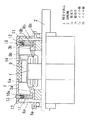
先ず、図1に示す第1の実施の形態の例から述べる。回転子鉄心1には回転軸2を挿通して一体化してあり、回転軸2には回転子鉄心1の両端方向の位置で夫々整流子3a,3bを装着してあり、回転子鉄心1に設けたスロット内には一方の整流子3bに接続したコイル線5bを下層として巻装してあると共に他方の整流子3aに接続したコイル線5aを上層として巻装してある。回転軸2の両端にはベアリングのような軸受6a,6bが装着され、モータケース7の両端の軸受台8a,8bに軸受6a,6bを装着することによって回転軸2と回転子鉄心1とが回転自在に装着されている。回転子鉄心1の外周に対向する対向面には界磁マグネット9がギャップを持って配置され、界磁マグネット9がモータケース7の内面に接着等で固定されている。
【0009】
両端の整流子3a,3bの外周には夫々カーボンブラシのようなブラシ10a,10bが配置され、ブラシ10a,10bを整流子3a,3bに接触させて給電できるようになっている。モータケース7には上記ブラシ10a,10bに対応するようにブラシホルダー11が配置され、ブラシホルダー11にブラシ10a,10bがスライド自在に保持されている。このブラシホルダー11にはブラシ10a,10bを付勢するバネ12や端子13が設けられている。コイル線5a,5bへの給電は、端子13→バネ12→ブラシ10a,10b→整流子3a,3b→コイル線5a,5bの順に行われるが、端子13→バネ12→ブラシ10a→整流子3a→コイル線5aの給電(a側)と、端子13→バネ12→ブラシ10b→整流子3b→コイル線5bの給電(b側)とは独立した回路を形成している。回転子鉄心1には回転子鉄心1と一緒に回転して冷却する冷却ファン14を一体に設けてある。
【0010】
上層のコイル線5aと下層のコイル線5bとはコイル線5bが太くて巻数小であり、コイル線5aが細くて巻数大である。下層のコイル線5bには整流子3bを介してバッテリーのような直流電源から電気(DC12V程度)が供給されるようになっており、上層のコイル線5aには整流子3aを介して商用電源のような交流電源(AC100V)から全波整流した直流の電気を供給できるようになっている。電源をバッテリーのような直流電源としたときは低電圧であるが、太くて巻数小のコイル線5bに給電し、電源を商用電源のような交流電源としたときは高電圧であるが、細くて巻数大のコイル線5aに給電するために供給される電力が略同じになり、直流のときも交流のときもモータ特性が殆ど同じになる。細いコイル線5aは発熱しやすいが、上層側に巻装してあるために蓄熱を防止できると共に冷却ファン14の風を受けて放熱性を向上でき、コイル部分の温度上昇を低減でき、コイル焼損防止が図れる。尚、太いコイル線5bは発熱が小さく、下層側に配置することによる不具合は発生しない。
【0011】
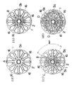
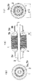
また図2、図3は他の例を示すものである。本例も上記例と基本的に同じであり、異なる点だけを述べる。回転子鉄心1のスロットの下層に巻装される太いコイル線5bは回転子鉄心1の歯16の5極に跨って対向面を同時に巻いている。所定の巻数に達すると反時計方向に歯16の1極分ずらせて上記と同じ巻線動作を行い、これを6回繰り返す。図2(a)はコイル線5bを巻き始めた状態であり、Aはコイル線5bの巻き始め位置を示す。図2(b)はコイル線5bを全部巻き終えた状態であり、Bはコイル線5bの巻き終わり位置を示す。下層のコイル線5bの巻線が完了すると、回転子鉄心1を90°回転させ、上層に巻装される細いコイル線5aをコイル線5bと同様に巻装する。図2(c)は上層のコイル線5aを巻き始めた状態であり、Cはコイル線5aの巻き始めの位置であり、コイル線5bの巻き終わりの位置Bに対して回転子鉄心1の周方向に90°位相がずれている。そして上層のコイル線5aにおいても下層のコイル線5bと同様に巻線を6回繰り返す。上記のようにコイル線5a,5bを巻くと、巻線径を同一とした場合、図3に示すコイル高さH及び巻線径φDを最小限に抑えることができる。このため巻線スペースを小さくすることができるため、特性が同一であればモータの小型化ができ、モータ体格が同じであればモータ特性を向上させることが可能となる。
【0012】
【発明の効果】
本発明の請求項1の発明は回転子鉄心の中心に挿通した回転軸に2つの整流子を装着すると共に前記回転子鉄心に設けたスロット内には一方の整流子に接続したコイル線を下層に巻装し、他方の整流子に接続したコイル線を上層に巻装した整流子モータであって、下層に巻装するコイル線と上層に巻装するコイル線との太さの関係を、下層(太線)>上層(細線)としたので、上層に巻装するコイル線を細線とすることになり、放熱しやすい位置に細いコイル線を配置することで発熱しやすい細いコイル線でも冷却効率を高くすることができ、過負荷使用においてもコイルが焼損しないようにできるものである。
【0013】
また本発明の請求項2の発明は、請求項1において、下層に巻装するコイル線の巻き終わり位置と上層に巻装するコイル線の巻き始め位置を回転子鉄心の周方向に略90°位相をずらせたので、コイル線を巻装する巻線スペースを小さくすることができ、モータを小型化したりモータ特性を向上したりできるものである。
【図面の簡単な説明】
【図1】本発明の実施の形態の一例の整流子モータ全体を示す半断面図である。
【図2】(a)(b)(c)(d)は同上の他の例のコイル線の巻装状態を説明する側面図である。
【図3】同上のコイル線を巻装した回転子鉄心を示し、(a)は正面図、(b)は左側面図、(c)は右側面図である。
【符号の説明】
1 固定子鉄心
2 回転軸
3a 整流子
3b 整流子
5a コイル線
5b コイル線[0001]
BACKGROUND OF THE INVENTION
The present invention relates to a commutator motor, and more particularly to a structure of a multi-winding commutator motor having two commutators.
[0002]
[Prior art]
In recent years, a commutator motor used in a vacuum cleaner or the like that can use both a DC power supply and an AC power supply has been desired.
[0003]
Conventionally, as this kind of commutator motor, two commutators are mounted at the center of the rotor core, and a coil wire connected to one commutator is wound around the rotor core and the other commutator is commutated. There is one in which a coil wire connected to a child is wound on an upper layer. In the case of a DC power source that uses a battery as the power source, power is supplied directly from the battery to one commutator, and in the case of an AC power source that uses the power source as a commercial power source, the AC is rectified by a rectifier and the DC power is supplied to the other commutator. To drive. Also, in the case of a DC power source (about DC 12V) using a power source as a power source and an AC power source (AC 100V) using a power source as a commercial power source, the motor characteristics need to be the same. A coil wire to be wound is wound with a thick wire so that the number of turns is small, and a coil using an AC power source such as a commercial power source as a power source is wound with a thin wire so that the number of turns is large. That is, the same level of power is supplied when a DC power source such as a battery having a low voltage is used as a power source or when an AC power source such as a commercial power source having a high voltage is used as a power source. In addition, the arrangement of the thick coil wire and the thin coil wire in the slot of the rotor core is to wind the thin coil wire in the lower layer and the thick coil wire in the upper layer in order to increase the space factor in the slot. It was a configuration.
[0004]
[Problems to be solved by the invention]
By the way, in the conventional commutator motor, the thin coil wire is wound around the lower layer in the slot and the upper thick coil wire is wound on the thin coil wire, so the cooling efficiency of the thin coil wire is poor. When the overload is used to store the heat, the coil burns out.
[0005]
The present invention has been made in view of the points described above, and an object of the present invention is to provide a commutator motor that has a high cooling efficiency for a thin coil wire and that does not burn out a coil even in overload use.
[0006]
[Means for Solving the Problems]
In order to solve the above problems, a commutator motor according to a first aspect of the present invention is provided with two
[0007]
A commutator motor according to a second aspect of the present invention is the commutator motor according to the first aspect, wherein the winding end position of the
[0008]
DETAILED DESCRIPTION OF THE INVENTION
First, the example of the first embodiment shown in FIG. 1 will be described. The rotor core 1 is integrated with a
[0009]
[0010]
The
[0011]
2 and 3 show other examples. This example is basically the same as the above example, and only different points will be described. The
[0012]
【The invention's effect】
According to a first aspect of the present invention, two commutators are mounted on a rotating shaft inserted through the center of a rotor core, and a coil wire connected to one commutator is placed in a lower layer in a slot provided in the rotor core. Is a commutator motor in which the coil wire connected to the other commutator is wound on the upper layer, and the relationship between the thickness of the coil wire wound on the lower layer and the coil wire wound on the upper layer is Lower layer (thick line)> upper layer (thin line), so the coil wire wound on the upper layer is a thin line, and even if it is a thin coil line that tends to generate heat by placing a thin coil line at a position where heat is easily radiated, cooling efficiency The coil can be prevented from burning out even in overload use.
[0013]
Further, the invention of
[Brief description of the drawings]
FIG. 1 is a half sectional view showing an entire commutator motor according to an embodiment of the present invention.
FIGS. 2A, 2B, 2C, and 2D are side views for explaining a winding state of another example of the coil wire.
FIG. 3 shows a rotor core around which the coil wire is wound, wherein (a) is a front view, (b) is a left side view, and (c) is a right side view.
[Explanation of symbols]
DESCRIPTION OF SYMBOLS 1
Claims (2)
Priority Applications (5)
| Application Number | Priority Date | Filing Date | Title |
|---|---|---|---|
| JP2000071139A JP3763243B2 (en) | 2000-03-14 | 2000-03-14 | Commutator motor |
| DE60131345T DE60131345T2 (en) | 2000-03-14 | 2001-03-13 | COMMUTATOR |
| PCT/JP2001/001946 WO2001069763A1 (en) | 2000-03-14 | 2001-03-13 | Commutator motor |
| EP01912298A EP1193843B1 (en) | 2000-03-14 | 2001-03-13 | Commutator motor |
| US09/926,500 US6737779B2 (en) | 2000-03-14 | 2001-03-13 | Commutator motor |
Applications Claiming Priority (1)
| Application Number | Priority Date | Filing Date | Title |
|---|---|---|---|
| JP2000071139A JP3763243B2 (en) | 2000-03-14 | 2000-03-14 | Commutator motor |
Publications (2)
| Publication Number | Publication Date |
|---|---|
| JP2001258230A JP2001258230A (en) | 2001-09-21 |
| JP3763243B2 true JP3763243B2 (en) | 2006-04-05 |
Family
ID=18589764
Family Applications (1)
| Application Number | Title | Priority Date | Filing Date |
|---|---|---|---|
| JP2000071139A Expired - Fee Related JP3763243B2 (en) | 2000-03-14 | 2000-03-14 | Commutator motor |
Country Status (5)
| Country | Link |
|---|---|
| US (1) | US6737779B2 (en) |
| EP (1) | EP1193843B1 (en) |
| JP (1) | JP3763243B2 (en) |
| DE (1) | DE60131345T2 (en) |
| WO (1) | WO2001069763A1 (en) |
Families Citing this family (13)
| Publication number | Priority date | Publication date | Assignee | Title |
|---|---|---|---|---|
| SE524541C2 (en) * | 2002-11-18 | 2004-08-24 | Uppsala Power Man Consultants | Power storage systems and vehicles fitted with such |
| KR100908373B1 (en) * | 2007-08-20 | 2009-07-20 | 엘에스산전 주식회사 | Drive motor used for closing spring charging device of air circuit breaker |
| IT1391208B1 (en) * | 2008-10-02 | 2011-11-18 | Ditec S P A | DIRECT CURRENT ELECTRIC MOTOR, PARTICULARLY FOR HANDLING AUTOMATIC SLIDING DOORS |
| US8373317B2 (en) * | 2009-05-04 | 2013-02-12 | Ingersoll Rand Company | RFI suppression system and method of mounting for DC cordless tools |
| US8310115B2 (en) * | 2010-07-23 | 2012-11-13 | General Electric Company | High power-density, high efficiency, non-permanent magnet electric machine |
| JP2013062902A (en) * | 2011-09-12 | 2013-04-04 | Denso Corp | Rotary electric machine |
| JP5890734B2 (en) * | 2012-04-10 | 2016-03-22 | 日立オートモティブシステムズ株式会社 | DC motor and vehicle equipped with the same |
| CN203027089U (en) * | 2012-12-12 | 2013-06-26 | 林楚辉 | A high and low voltage combined double commutator DC permanent magnet motor |
| JP6239343B2 (en) * | 2013-10-25 | 2017-11-29 | 株式会社ミツバ | Armature and electric motor |
| JP6565393B2 (en) * | 2015-07-06 | 2019-08-28 | 株式会社デンソー | Armature, armature manufacturing method, rotating electric machine |
| KR101961339B1 (en) * | 2017-11-27 | 2019-03-25 | 주식회사 만도 | Dual winding dc motor |
| DE102019204035A1 (en) * | 2019-03-25 | 2020-10-01 | Mando Corporation | Brake or steering system with redundant components |
| JP7314845B2 (en) * | 2020-03-24 | 2023-07-26 | 株式会社デンソー | motor |
Family Cites Families (16)
| Publication number | Priority date | Publication date | Assignee | Title |
|---|---|---|---|---|
| US2660681A (en) * | 1949-03-01 | 1953-11-24 | Bendix Aviat Corp | Winding arrangement for variable transformers |
| DE828885C (en) | 1950-04-04 | 1952-01-21 | Siemens Schuckertwerke A G | Two-stage or multi-stage direct current machine, in particular amplifier machine |
| US3525912A (en) * | 1966-03-28 | 1970-08-25 | Scovill Manufacturing Co | Selectable power source for a motor driven appliance |
| DE2340500A1 (en) | 1973-08-10 | 1975-03-06 | Weiss Paul Fa | FHP DC motor with tachogenerator windings on laminated rotor - has excitation windings and commutators at shaft ends |
| JPS5447016U (en) * | 1977-09-07 | 1979-04-02 | ||
| JPS5813746B2 (en) * | 1977-09-22 | 1983-03-15 | 日野自動車株式会社 | Internal combustion engine combustion chamber photography device |
| US4296344A (en) * | 1979-03-13 | 1981-10-20 | General Electric Company | Multi-speed motor |
| US4329610A (en) * | 1980-04-14 | 1982-05-11 | Black & Decker Inc. | Armature winding pattern for an electric motor |
| JPS5785563A (en) | 1980-11-18 | 1982-05-28 | Ricoh Co Ltd | Rotor for motor |
| DE3233015C1 (en) * | 1982-09-06 | 1984-03-15 | Henschel Gerätebau GmbH, 3035 Hodenhagen | Electric motor for optional connection to direct or alternating current |
| JPS6319450A (en) * | 1986-07-11 | 1988-01-27 | Kanzaki Kokyukoki Mfg Co Ltd | Reverse revolving machine for vessel |
| JP2511928B2 (en) * | 1987-02-06 | 1996-07-03 | 松下電器産業株式会社 | Commutator motor applied equipment |
| DE3723369C1 (en) * | 1987-07-15 | 1988-11-24 | Daimler Benz Ag | Permanent-magnet-excited DC machine |
| US5336956A (en) * | 1992-11-23 | 1994-08-09 | Lambert Haner | Brushless dynamo machine with novel armature construction |
| JPH06335214A (en) | 1993-05-19 | 1994-12-02 | Matsushita Electric Ind Co Ltd | Commutator motor |
| JPH1189201A (en) * | 1997-09-09 | 1999-03-30 | Ryobi Ltd | Breakage preventing mechanism for coil of rotor for power tool |
-
2000
- 2000-03-14 JP JP2000071139A patent/JP3763243B2/en not_active Expired - Fee Related
-
2001
- 2001-03-13 US US09/926,500 patent/US6737779B2/en not_active Expired - Fee Related
- 2001-03-13 DE DE60131345T patent/DE60131345T2/en not_active Expired - Lifetime
- 2001-03-13 EP EP01912298A patent/EP1193843B1/en not_active Expired - Lifetime
- 2001-03-13 WO PCT/JP2001/001946 patent/WO2001069763A1/en not_active Ceased
Also Published As
| Publication number | Publication date |
|---|---|
| JP2001258230A (en) | 2001-09-21 |
| EP1193843B1 (en) | 2007-11-14 |
| US6737779B2 (en) | 2004-05-18 |
| DE60131345T2 (en) | 2008-09-04 |
| US20030057788A1 (en) | 2003-03-27 |
| EP1193843A1 (en) | 2002-04-03 |
| WO2001069763A1 (en) | 2001-09-20 |
| EP1193843A4 (en) | 2003-04-09 |
| DE60131345D1 (en) | 2007-12-27 |
Similar Documents
| Publication | Publication Date | Title |
|---|---|---|
| JP3763243B2 (en) | Commutator motor | |
| JP3905300B2 (en) | AC generator for vehicles | |
| JP3954504B2 (en) | motor | |
| JP2009095229A (en) | Electric motor | |
| JP4940252B2 (en) | Manufacturing method of rotating electrical machine | |
| JP3256696B2 (en) | AC generator | |
| US8946963B2 (en) | Polyphase stator for internally ventilated rotating electrical machine, and rotating electrical machine comprising such stator | |
| JP3950114B2 (en) | Induction motor stator | |
| JP2002044890A (en) | Rotating electric machine | |
| JP2000341918A (en) | Rotor of rotating electric machine and method of magnetizing its magnetic body | |
| JPWO2007088598A1 (en) | Rotating electric machine | |
| CN219041488U (en) | Rotor structure of claw pole motor | |
| JP3767136B2 (en) | Rotor for rotating electrical machine and method for manufacturing the same | |
| JP2002238225A (en) | AC generator | |
| JP2002272031A (en) | Synchronous reluctance motor | |
| KR100645585B1 (en) | DC motor | |
| CN102983645B (en) | Brush motor, fan, rotor and forming method thereof | |
| KR20180031647A (en) | A generator using of multibrush and slip ring | |
| JP3855839B2 (en) | AC rotating electric machine for vehicles | |
| JP5452403B2 (en) | Commutator motor, electric blower and vacuum cleaner | |
| KR100557886B1 (en) | Rotor of automotive alternator | |
| CN221669658U (en) | Electric tool motor | |
| CN202183715U (en) | DC motor for cooling fan of automobile engine | |
| JP2002238203A (en) | AC generator | |
| JPS6325891Y2 (en) |
Legal Events
| Date | Code | Title | Description |
|---|---|---|---|
| TRDD | Decision of grant or rejection written | ||
| A01 | Written decision to grant a patent or to grant a registration (utility model) |
Free format text: JAPANESE INTERMEDIATE CODE: A01 Effective date: 20051227 |
|
| A61 | First payment of annual fees (during grant procedure) |
Free format text: JAPANESE INTERMEDIATE CODE: A61 Effective date: 20060109 |
|
| FPAY | Renewal fee payment (event date is renewal date of database) |
Free format text: PAYMENT UNTIL: 20090127 Year of fee payment: 3 |
|
| S533 | Written request for registration of change of name |
Free format text: JAPANESE INTERMEDIATE CODE: R313533 |
|
| FPAY | Renewal fee payment (event date is renewal date of database) |
Free format text: PAYMENT UNTIL: 20090127 Year of fee payment: 3 |
|
| R350 | Written notification of registration of transfer |
Free format text: JAPANESE INTERMEDIATE CODE: R350 |
|
| FPAY | Renewal fee payment (event date is renewal date of database) |
Free format text: PAYMENT UNTIL: 20100127 Year of fee payment: 4 |
|
| FPAY | Renewal fee payment (event date is renewal date of database) |
Free format text: PAYMENT UNTIL: 20100127 Year of fee payment: 4 |
|
| FPAY | Renewal fee payment (event date is renewal date of database) |
Free format text: PAYMENT UNTIL: 20110127 Year of fee payment: 5 |
|
| FPAY | Renewal fee payment (event date is renewal date of database) |
Free format text: PAYMENT UNTIL: 20120127 Year of fee payment: 6 |
|
| FPAY | Renewal fee payment (event date is renewal date of database) |
Free format text: PAYMENT UNTIL: 20120127 Year of fee payment: 6 |
|
| FPAY | Renewal fee payment (event date is renewal date of database) |
Free format text: PAYMENT UNTIL: 20130127 Year of fee payment: 7 |
|
| FPAY | Renewal fee payment (event date is renewal date of database) |
Free format text: PAYMENT UNTIL: 20130127 Year of fee payment: 7 |
|
| LAPS | Cancellation because of no payment of annual fees |