EP2650992A2 - Dichtungstülle für elektrisches Einbaugerät - Google Patents
Dichtungstülle für elektrisches Einbaugerät Download PDFInfo
- Publication number
- EP2650992A2 EP2650992A2 EP13160632.9A EP13160632A EP2650992A2 EP 2650992 A2 EP2650992 A2 EP 2650992A2 EP 13160632 A EP13160632 A EP 13160632A EP 2650992 A2 EP2650992 A2 EP 2650992A2
- Authority
- EP
- European Patent Office
- Prior art keywords
- sock
- retaining means
- sealing
- opening zone
- electrical equipment
- Prior art date
- Legal status (The legal status is an assumption and is not a legal conclusion. Google has not performed a legal analysis and makes no representation as to the accuracy of the status listed.)
- Withdrawn
Links
Images


Classifications
-
- H—ELECTRICITY
- H02—GENERATION; CONVERSION OR DISTRIBUTION OF ELECTRIC POWER
- H02G—INSTALLATION OF ELECTRIC CABLES OR LINES, OR OF COMBINED OPTICAL AND ELECTRIC CABLES OR LINES
- H02G3/00—Installations of electric cables or lines or protective tubing therefor in or on buildings, equivalent structures or vehicles
- H02G3/02—Details
- H02G3/08—Distribution boxes; Connection or junction boxes
- H02G3/088—Dustproof, splashproof, drip-proof, waterproof, or flameproof casings or inlets
-
- H—ELECTRICITY
- H02—GENERATION; CONVERSION OR DISTRIBUTION OF ELECTRIC POWER
- H02G—INSTALLATION OF ELECTRIC CABLES OR LINES, OR OF COMBINED OPTICAL AND ELECTRIC CABLES OR LINES
- H02G3/00—Installations of electric cables or lines or protective tubing therefor in or on buildings, equivalent structures or vehicles
- H02G3/02—Details
- H02G3/08—Distribution boxes; Connection or junction boxes
- H02G3/12—Distribution boxes; Connection or junction boxes for flush mounting
- H02G3/121—Distribution boxes; Connection or junction boxes for flush mounting in plain walls
-
- H—ELECTRICITY
- H02—GENERATION; CONVERSION OR DISTRIBUTION OF ELECTRIC POWER
- H02G—INSTALLATION OF ELECTRIC CABLES OR LINES, OR OF COMBINED OPTICAL AND ELECTRIC CABLES OR LINES
- H02G3/00—Installations of electric cables or lines or protective tubing therefor in or on buildings, equivalent structures or vehicles
- H02G3/02—Details
- H02G3/08—Distribution boxes; Connection or junction boxes
- H02G3/12—Distribution boxes; Connection or junction boxes for flush mounting
- H02G3/123—Distribution boxes; Connection or junction boxes for flush mounting in thin walls
-
- H—ELECTRICITY
- H02—GENERATION; CONVERSION OR DISTRIBUTION OF ELECTRIC POWER
- H02G—INSTALLATION OF ELECTRIC CABLES OR LINES, OR OF COMBINED OPTICAL AND ELECTRIC CABLES OR LINES
- H02G3/00—Installations of electric cables or lines or protective tubing therefor in or on buildings, equivalent structures or vehicles
- H02G3/02—Details
- H02G3/08—Distribution boxes; Connection or junction boxes
- H02G3/14—Fastening of cover or lid to box
Definitions
- the invention relates to a sealing sock for electrical equipment and also a built-in electrical equipment in a box recess.
- a sealing sock for a built-in electrical device makes it possible to give the built-in electrical device at least dust-tightness. Airtightness and watertightness is also sought in order to achieve, for example, energy savings by avoiding losses.
- a sealing sock for electrical equipment includes a casing of material flexible housing adapted to contain a functional block of a built-in electrical equipment, the envelope comprising at least one opening area for receiving a retaining means through the functional block.
- a sock 1 comprises a flexible material envelope 2 and an opening zone 3.
- the envelope 2 is adapted to contain a functional block 10 of a built-in electrical equipment.
- the sock 1 thus surrounds the functional block 10 so as to protect it from a runoff of water, dust carried by drafts and drafts that can cause heat loss.
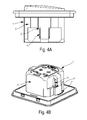
- This functional block 10 comprises at least one retaining means 11 which is received in the opening zone 3 by passing through it.
- the opening zone 3 is an opening in the casing 2.
- the retaining means 11 engaged in the opening passes through both sides of the casing 2 of the sealing sock 1 ( Figure 4A ).
- the opening zone 3 is an area of the envelope which has a thickness E less than the thickness general envelope 2.
- the thickness E is chosen to allow the retaining means 11 of the functional block 10 to tear the opening zone 3 when it engages in said zone.
- the retaining means 11 thus crosses on both sides the casing 2 of the sealing sock 1 ( Figure 4A ).
- the opening zone 3 may be made of a material different from the material of the envelope 2.
- the opening zone in this second embodiment, is particularly difficult to achieve, especially in molding, because of the precision necessary for its realization. It is advantageous to use a particularly fluid material for the realization of this area to ensure the proper filling of the material in this area.
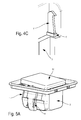
- FIGS. 5A and 5B illustrate the sock 1 and the envelope 2 having undergone deformation following a rotational movement of the retaining means 11.
- This deformation has the advantage of optimally ensuring the sealing of the functional block 10 protected by the sock 1, in now the opening zone 3 in contact with the retaining means 11 without generating a void space between the opening zone 3 and the retaining means 11, the opening zone 3 permanently matching the retaining means 11.
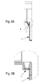
- the sock 1 may comprise a reinforcement 5 which forms a rigid zone around the opening zone 3.
- the function of the reinforcement 5 is to seal the sock around the opening zone 3 and the means of retaining 11 which crosses it.
- the reinforcement 5 can provide a guiding role of the retaining means 11 in the opening zone 3 in the second embodiment, that is to say when the opening zone is intended to be torn by the retaining means when it is engaged in the opening zone, as well as a role of limiting the creation of microcracks, or the initiation of rupture of the material, constituting the opening zone, beyond a predefined limit, during tearing or displacement of the retaining means 11 in the opening zone 3.
- the reinforcement 5 is integral with the retaining means 11 engaged so as to follow the movements of the retaining means 11.
- the retaining means 11 in rotation bears on the reinforcement 5 which, by its rigidity and the flexibility of the casing 2, forces the deformation of the sock 1.
- the retaining means 11 of the functional block 10 may be a claw system such as that described in the application FR 1101465 of the Applicant.
- the claw system described therein is adapted to switch between a retracted position and an extended position.
- the functional block 10 may comprise a frame, a screw engaged through an opening provided in the frame, a claw, taking the place of retaining means 11, adapted to tilt relative to the frame between a retracted position and a position deployed, and a nut screwed onto the screw and arranged to tilt the claw from its retracted position to its deployed position.
- the frame has a ramp and the nut is arranged to slide on this ramp when unscrewing the screw so that it is forced to pivot about an axis to push the claw from its deployed position to its position retracted.
- the claw moves from an extended position to a retracted position by a rotational movement. The passage between these two positions is illustrated by comparing the position of the retaining means 11 and the reinforcement 5 between the figures 4 (A, B and C) and figures 5 (A and B).
- the functional block retaining means to be contained in the sock must be in the retracted position to ensure easy insertion of the functional block retaining means into the opening area.
- the retaining means may be a screw intended to pass through an opening zone of the envelope of the sock.
- the opening zone is an area whose thickness E is less than the overall thickness of the envelope. The screw passing through this opening zone tears said opening zone 3 '. A portion of the screw covers the opening zone 3 'sealing the sock 1 at the opening zone torn by the screw.
- the sock 1 is made of an electrically insulating and waterproof material, for example styrene-ethylene / butadiene-styrene (SEBS).
- SEBS styrene-ethylene / butadiene-styrene
- the overall thickness of the casing must be sufficient to ensure optimum sealing against water, air and dust, but this thickness must also take account of the moldability constraints during the industrial production of a casing. such sock.
- the overall thickness of the envelope may be between 0.15 and 0.8 mm.
- the overall thickness of the envelope may be 0.4 mm or 0.5 mm in order to satisfy the water, air and dust tightness constraints while ensuring easy realization of the sock.
- the figure 7 illustrates a functional block 10 fixed on a sealing sock 1.
- the sock 1 is fixed to the functional block 10 by means of at least one protrusion 6 disposed in a corner of the sock 1 (the protrusion 6 is also visible, by example, on Figures 1, 2 and 3 ).
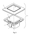
- the invention also relates to a switchgear electrical equipment 20 in a recess box by translation along a main axis X.
- This apparatus comprises a front plate 21, a functional block 10 and a sealing sock 1 according to one of the previously described embodiments.
- the functional block 10 is intended to be inserted into the sealing sock 1.
- the retaining means 11 of the functional block passes through the opening zone 3 of the sock.
- the front plate 21 can be snapped onto the functional block 10.
Landscapes
- Engineering & Computer Science (AREA)
- Architecture (AREA)
- Civil Engineering (AREA)
- Structural Engineering (AREA)
- Casings For Electric Apparatus (AREA)
- Packages (AREA)
- Treatment Of Fiber Materials (AREA)
Applications Claiming Priority (1)
| Application Number | Priority Date | Filing Date | Title |
|---|---|---|---|
| FR1253350A FR2989527B1 (fr) | 2012-04-12 | 2012-04-12 | Chaussette d'etancheite pour appareillage electrique encastrable |
Publications (2)
| Publication Number | Publication Date |
|---|---|
| EP2650992A2 true EP2650992A2 (de) | 2013-10-16 |
| EP2650992A3 EP2650992A3 (de) | 2017-05-10 |
Family
ID=46754563
Family Applications (1)
| Application Number | Title | Priority Date | Filing Date |
|---|---|---|---|
| EP13160632.9A Withdrawn EP2650992A3 (de) | 2012-04-12 | 2013-03-22 | Dichtungstülle für elektrisches Einbaugerät |
Country Status (2)
| Country | Link |
|---|---|
| EP (1) | EP2650992A3 (de) |
| FR (1) | FR2989527B1 (de) |
Cited By (2)
| Publication number | Priority date | Publication date | Assignee | Title |
|---|---|---|---|---|
| FR3066331A1 (fr) * | 2017-05-10 | 2018-11-16 | Eur'ohm | Support de mecanisme d'appareillage electrique |
| CN109768657A (zh) * | 2017-11-10 | 2019-05-17 | 勒格朗法国公司 | 电气设备 |
Citations (3)
| Publication number | Priority date | Publication date | Assignee | Title |
|---|---|---|---|---|
| FR1101465A (fr) | 1953-06-18 | 1955-10-06 | Ford | Suspension à roues indépendantes perfectionnée pour véhicule automobile |
| DE102008015128A1 (de) | 2008-03-20 | 2009-10-01 | Abb Ag | Dichthülle für ein Unterputz-Installationsgerät |
| FR2959882A1 (fr) | 2010-05-04 | 2011-11-11 | Legrand France | Appareillage electrique encastrable a etancheite amelioree |
Family Cites Families (4)
| Publication number | Priority date | Publication date | Assignee | Title |
|---|---|---|---|---|
| US3684819A (en) * | 1971-02-25 | 1972-08-15 | Ronald G Wilson | Sealing boot for an electrical receptacle |
| CA1273094A (en) * | 1986-01-25 | 1990-08-21 | Hiroshi Kaneda | Air and dust proof cover for flush mounting wiring fixture |
| JPH07274346A (ja) * | 1994-03-29 | 1995-10-20 | Mirai Ind Co Ltd | ボックス用防塵パッキン |
| DE102005016083A1 (de) * | 2005-04-08 | 2006-10-12 | Abb Patent Gmbh | Spreizkrallenvorrichtung für ein Unterputz-Installationsgerät |
-
2012
- 2012-04-12 FR FR1253350A patent/FR2989527B1/fr active Active
-
2013
- 2013-03-22 EP EP13160632.9A patent/EP2650992A3/de not_active Withdrawn
Patent Citations (3)
| Publication number | Priority date | Publication date | Assignee | Title |
|---|---|---|---|---|
| FR1101465A (fr) | 1953-06-18 | 1955-10-06 | Ford | Suspension à roues indépendantes perfectionnée pour véhicule automobile |
| DE102008015128A1 (de) | 2008-03-20 | 2009-10-01 | Abb Ag | Dichthülle für ein Unterputz-Installationsgerät |
| FR2959882A1 (fr) | 2010-05-04 | 2011-11-11 | Legrand France | Appareillage electrique encastrable a etancheite amelioree |
Cited By (3)
| Publication number | Priority date | Publication date | Assignee | Title |
|---|---|---|---|---|
| FR3066331A1 (fr) * | 2017-05-10 | 2018-11-16 | Eur'ohm | Support de mecanisme d'appareillage electrique |
| CN109768657A (zh) * | 2017-11-10 | 2019-05-17 | 勒格朗法国公司 | 电气设备 |
| CN109768657B (zh) * | 2017-11-10 | 2022-11-29 | 勒格朗法国公司 | 电气设备 |
Also Published As
| Publication number | Publication date |
|---|---|
| EP2650992A3 (de) | 2017-05-10 |
| FR2989527A1 (fr) | 2013-10-18 |
| FR2989527B1 (fr) | 2016-02-19 |
Similar Documents
| Publication | Publication Date | Title |
|---|---|---|
| EP1415059B1 (de) | Griff für kraftfahrzeugflügel | |
| EP3109878B1 (de) | Vakuumschalter und elektrisches schutzgerät mit einem solchen vakuumschalter | |
| EP1284335B1 (de) | Türgriff mit Elektronikmodul insbesondere für Kraftfahrzeuge | |
| EP2650992A2 (de) | Dichtungstülle für elektrisches Einbaugerät | |
| EP0695900A1 (de) | Dichter Durchgang für Fernmeldekabel | |
| EP1848066A2 (de) | Dichte, gesicherte Stromanschlussvorrichtung | |
| EP3319835B1 (de) | Beleuchtungsvorrichtungselement zur reduzierung der wasserretention in der nähe einer dichtung | |
| EP3840136B1 (de) | Mechanismus eines elektrischen geräts, entsprechende elektrische anordung und entsprechendes elektrisches gerät | |
| EP3524879B1 (de) | Abgedichteter behälter für sicherheitsbeleuchtung | |
| EP3039757A1 (de) | Vorrichtung zur dichtung von gaslecks in einer berstscheibe einer kammer einer gasisolierten elektrischen unterstation oder eines hochspannungsschutzschalters | |
| EP2124294B1 (de) | Verbindungsgehäuse und Verbindungszusammenbau mit einem solchen Gehäuse | |
| EP3840151B1 (de) | Schaltkasten und zugehörige elektrische ausrüstung | |
| EP3404773A1 (de) | Haltevorrichtung mindestens eines elektrisch leitenden rohrs auf einer elektrisch leitfähigen struktur | |
| FR2677210A1 (fr) | Mode de protection d'une plaque de facade pour appareil electrique, et plaque de facade et appareil electrique correspondants. | |
| EP2432306B1 (de) | Fensterladen der Verschleierung einer Interessenzone | |
| FR2996353A1 (fr) | Boitier a fusible pour moteur electrique, notamment de vehicule automobile | |
| FR2927198A1 (fr) | Dispositif electrique de raccordement | |
| FR2914790A1 (fr) | Prise de courant a double configuration d'alimentation | |
| CA2905578A1 (fr) | Panneau de disjoncteurs | |
| EP4075611A1 (de) | Schutzvorrichtung für einen elektrischen verbindungsstecker, baugruppe mit einer zierabdeckung und dieser schutzvorrichtung und elektrisches gerät, das diese schutzvorrichtung umfasst | |
| FR2799058A1 (fr) | Adaptateur pour appareillage electrique presentant un sens de montage | |
| FR3111600A1 (fr) | Réservoir lave-glace de type souple doté d’un capteur de niveau | |
| FR2983892A1 (fr) | Dispositif de maintien d'au moins une boite de reservation, notamment destine au maintien d'au moins une boite de reservation entre deux banches | |
| EP3840002A1 (de) | Zierblende und elektrischer schalter, der eine solche zierblende umfasst | |
| FR2804791A1 (fr) | Appareillages electriques a voyant |
Legal Events
| Date | Code | Title | Description |
|---|---|---|---|
| PUAI | Public reference made under article 153(3) epc to a published international application that has entered the european phase |
Free format text: ORIGINAL CODE: 0009012 |
|
| AK | Designated contracting states |
Kind code of ref document: A2 Designated state(s): AL AT BE BG CH CY CZ DE DK EE ES FI FR GB GR HR HU IE IS IT LI LT LU LV MC MK MT NL NO PL PT RO RS SE SI SK SM TR |
|
| AX | Request for extension of the european patent |
Extension state: BA ME |
|
| PUAL | Search report despatched |
Free format text: ORIGINAL CODE: 0009013 |
|
| AK | Designated contracting states |
Kind code of ref document: A3 Designated state(s): AL AT BE BG CH CY CZ DE DK EE ES FI FR GB GR HR HU IE IS IT LI LT LU LV MC MK MT NL NO PL PT RO RS SE SI SK SM TR |
|
| AX | Request for extension of the european patent |
Extension state: BA ME |
|
| RIC1 | Information provided on ipc code assigned before grant |
Ipc: H02G 3/08 20060101AFI20170403BHEP Ipc: H02G 3/12 20060101ALI20170403BHEP Ipc: H02G 3/14 20060101ALI20170403BHEP |
|
| STAA | Information on the status of an ep patent application or granted ep patent |
Free format text: STATUS: THE APPLICATION IS DEEMED TO BE WITHDRAWN |
|
| 18D | Application deemed to be withdrawn |
Effective date: 20171003 |