EP2650984B1 - Method for connecting wire material and twisted wire, and stator of electric motor or generator - Google Patents
Method for connecting wire material and twisted wire, and stator of electric motor or generator Download PDFInfo
- Publication number
- EP2650984B1 EP2650984B1 EP11847473.3A EP11847473A EP2650984B1 EP 2650984 B1 EP2650984 B1 EP 2650984B1 EP 11847473 A EP11847473 A EP 11847473A EP 2650984 B1 EP2650984 B1 EP 2650984B1
- Authority
- EP
- European Patent Office
- Prior art keywords
- twisted wire
- wire
- face
- core wires
- vibration tool
- Prior art date
- Legal status (The legal status is an assumption and is not a legal conclusion. Google has not performed a legal analysis and makes no representation as to the accuracy of the status listed.)
- Active
Links
- 239000000463 material Substances 0.000 title claims description 71
- 238000000034 method Methods 0.000 title claims description 35
- 230000000694 effects Effects 0.000 description 10
- 230000001788 irregular Effects 0.000 description 8
- WABPQHHGFIMREM-UHFFFAOYSA-N lead(0) Chemical group [Pb] WABPQHHGFIMREM-UHFFFAOYSA-N 0.000 description 8
- RYGMFSIKBFXOCR-UHFFFAOYSA-N Copper Chemical compound [Cu] RYGMFSIKBFXOCR-UHFFFAOYSA-N 0.000 description 5
- 230000005540 biological transmission Effects 0.000 description 4
- 229910052802 copper Inorganic materials 0.000 description 4
- 239000010949 copper Substances 0.000 description 4
- 238000009792 diffusion process Methods 0.000 description 3
- 230000002411 adverse Effects 0.000 description 1
- 239000011248 coating agent Substances 0.000 description 1
- 238000000576 coating method Methods 0.000 description 1
- 230000003247 decreasing effect Effects 0.000 description 1
- 230000001419 dependent effect Effects 0.000 description 1
- 238000012986 modification Methods 0.000 description 1
- 230000004048 modification Effects 0.000 description 1
- 230000010355 oscillation Effects 0.000 description 1
- 230000002093 peripheral effect Effects 0.000 description 1
- 238000003672 processing method Methods 0.000 description 1
- 230000000644 propagated effect Effects 0.000 description 1
- 239000007787 solid Substances 0.000 description 1
Images


Classifications
-
- H—ELECTRICITY
- H02—GENERATION; CONVERSION OR DISTRIBUTION OF ELECTRIC POWER
- H02K—DYNAMO-ELECTRIC MACHINES
- H02K3/00—Details of windings
- H02K3/46—Fastening of windings on the stator or rotor structure
- H02K3/50—Fastening of winding heads, equalising connectors, or connections thereto
-
- B—PERFORMING OPERATIONS; TRANSPORTING
- B23—MACHINE TOOLS; METAL-WORKING NOT OTHERWISE PROVIDED FOR
- B23K—SOLDERING OR UNSOLDERING; WELDING; CLADDING OR PLATING BY SOLDERING OR WELDING; CUTTING BY APPLYING HEAT LOCALLY, e.g. FLAME CUTTING; WORKING BY LASER BEAM
- B23K20/00—Non-electric welding by applying impact or other pressure, with or without the application of heat, e.g. cladding or plating
- B23K20/10—Non-electric welding by applying impact or other pressure, with or without the application of heat, e.g. cladding or plating making use of vibrations, e.g. ultrasonic welding
-
- B—PERFORMING OPERATIONS; TRANSPORTING
- B23—MACHINE TOOLS; METAL-WORKING NOT OTHERWISE PROVIDED FOR
- B23K—SOLDERING OR UNSOLDERING; WELDING; CLADDING OR PLATING BY SOLDERING OR WELDING; CUTTING BY APPLYING HEAT LOCALLY, e.g. FLAME CUTTING; WORKING BY LASER BEAM
- B23K31/00—Processes relevant to this subclass, specially adapted for particular articles or purposes, but not covered by only one of the preceding main groups
- B23K31/02—Processes relevant to this subclass, specially adapted for particular articles or purposes, but not covered by only one of the preceding main groups relating to soldering or welding
-
- H—ELECTRICITY
- H01—ELECTRIC ELEMENTS
- H01R—ELECTRICALLY-CONDUCTIVE CONNECTIONS; STRUCTURAL ASSOCIATIONS OF A PLURALITY OF MUTUALLY-INSULATED ELECTRICAL CONNECTING ELEMENTS; COUPLING DEVICES; CURRENT COLLECTORS
- H01R43/00—Apparatus or processes specially adapted for manufacturing, assembling, maintaining, or repairing of line connectors or current collectors or for joining electric conductors
- H01R43/02—Apparatus or processes specially adapted for manufacturing, assembling, maintaining, or repairing of line connectors or current collectors or for joining electric conductors for soldered or welded connections
- H01R43/0207—Ultrasonic-, H.F.-, cold- or impact welding
-
- H—ELECTRICITY
- H02—GENERATION; CONVERSION OR DISTRIBUTION OF ELECTRIC POWER
- H02K—DYNAMO-ELECTRIC MACHINES
- H02K15/00—Methods or apparatus specially adapted for manufacturing, assembling, maintaining or repairing of dynamo-electric machines
- H02K15/0056—Manufacturing winding connections
- H02K15/0062—Manufacturing the terminal arrangement per se; Connecting the terminals to an external circuit
-
- H—ELECTRICITY
- H02—GENERATION; CONVERSION OR DISTRIBUTION OF ELECTRIC POWER
- H02K—DYNAMO-ELECTRIC MACHINES
- H02K15/00—Methods or apparatus specially adapted for manufacturing, assembling, maintaining or repairing of dynamo-electric machines
- H02K15/0056—Manufacturing winding connections
- H02K15/0068—Connecting winding sections; Forming leads; Connecting leads to terminals
-
- B—PERFORMING OPERATIONS; TRANSPORTING
- B23—MACHINE TOOLS; METAL-WORKING NOT OTHERWISE PROVIDED FOR
- B23K—SOLDERING OR UNSOLDERING; WELDING; CLADDING OR PLATING BY SOLDERING OR WELDING; CUTTING BY APPLYING HEAT LOCALLY, e.g. FLAME CUTTING; WORKING BY LASER BEAM
- B23K2101/00—Articles made by soldering, welding or cutting
- B23K2101/32—Wires
-
- B—PERFORMING OPERATIONS; TRANSPORTING
- B23—MACHINE TOOLS; METAL-WORKING NOT OTHERWISE PROVIDED FOR
- B23K—SOLDERING OR UNSOLDERING; WELDING; CLADDING OR PLATING BY SOLDERING OR WELDING; CUTTING BY APPLYING HEAT LOCALLY, e.g. FLAME CUTTING; WORKING BY LASER BEAM
- B23K2101/00—Articles made by soldering, welding or cutting
- B23K2101/36—Electric or electronic devices
- B23K2101/38—Conductors
-
- B—PERFORMING OPERATIONS; TRANSPORTING
- B23—MACHINE TOOLS; METAL-WORKING NOT OTHERWISE PROVIDED FOR
- B23K—SOLDERING OR UNSOLDERING; WELDING; CLADDING OR PLATING BY SOLDERING OR WELDING; CUTTING BY APPLYING HEAT LOCALLY, e.g. FLAME CUTTING; WORKING BY LASER BEAM
- B23K2103/00—Materials to be soldered, welded or cut
- B23K2103/08—Non-ferrous metals or alloys
- B23K2103/12—Copper or alloys thereof
Definitions
- the present invention relates to a method for connecting a wire material, and to an electric motor or a generator using it.
- the electric motor and the generator represented by a motor or an alternator have a single wire of copper, whose electric resistance is low, wound as a wire material around the core of a rotor or a stator, and generates a magnetic field by passing an electric current.
- the electric current passage of the electric motor and the generator with an outside power-supply unit is often performed with a twisted wire as a lead wire connected to an end of the wire material. Since the twisted wire is composed of a plurality of thin core wires, it has high flexibility and is used generally because it can be wired easily to the power-supply unit or the like.
- the caulking terminal has a disadvantage that the connected portion becomes large because the peripheries of the wire material and the twisted wire are surrounded by the caulking member.
- ultrasonic bonding is available as another connecting method used instead of the caulking terminal.
- the ultrasonic bonding is a bonding method which uses a device comprising a vibration tool for ultrasonic oscillation and an anvil for fixing a member, holds the member between the vibration tool and the anvil, and applies ultrasonic vibration while pressurizing to cause a diffusion reaction on the interface between two bonding members. Since the ultrasonic bonding does not need to use an additional member such as the caulking terminal, it is effective to make the connected portion compact and to save a space.
- Patent Literature 1 A method for ultrasonic bonding of a twisted wire with another member is disclosed in Patent Literature 1. It shows that the twisted wire is previously hardened by ultrasonic bonding, and the hardened twisted wire and another connecting member are additionally bonded by ultrasonic waves. As another bonding member, a connection terminal is disclosed in its embodiments.
- Patent Literature 1 is hardly applicable to a high-power electric motor and generator which pass large current to the wire material. In other words, it is difficult to harden the whole twisted wire by ultrasonic bonding because the twisted wire as a lead wire has a large diameter.
- a diameter (thickness) of the wire material wound on the core is smaller than the above described propagation distance, bonding can be made by applying ultrasonic vibration from the wire material side.
- the wire material has a large diameter in the high-power electric motor and generator, the ultrasonic vibration does not propagate to the interface between the twisted wire and the wire material even if the ultrasonic vibration is applied from the wire material side, and bonding cannot be made.
- the present invention has been achieved in view of the circumstances described above and aims to provide a wire material connecting method for directly bonding the wire material and the twisted wire having a large diameter of the electric motor and the generator by ultrasonic bonding, and a compact, high-power electric motor and generator which have the wire material and the twisted wire connected by the above connecting method.
- a method for connecting the twisted wire according to claim 1 having a plurality of core wires and the wire material performs connection including a first step that the twisted wire is hardened by ultrasonic vibration using a pressurized vibration tool, and a second step that the twisted wire and the wire material are connected by applying ultrasonic waves in the state that the surface of the twisted wire hardened by pressurizing with the vibration tool is contacted to the wire material, and a stator according to claim 7 are proposed.
- Dependent claims relate to preferred embodiments of the present invention.
- connection having sufficient bonding strength and a small connected portion can be obtained by a method for connecting a wire material for direct bonding by ultrasonic bonding of the wire material and the twisted wire having a large wire diameter of a high-power electric motor and generator.
- FIG 1 to FIG 6 One embodiment of the method for connecting the wire material of the present invention is described using FIG 1 to FIG 6 .
- FIG. 3 is a view illustrating a structure of an electric motor 30 according to one embodiment of the present invention.
- the electric motor 30 has a rotor 1, a stator core 2, and a wire material 22 wound on the stator core 2.
- a lead wire 20 is connected to an end of the wire material 22 to pass electric current to the electric motor 30.
- the wire material 22 is a single metallic wire, but for the lead wire 20, there is commonly used a twisted wire which allows the passage of large electric current and can have high flexibility so that it can be wired easily even if its diameter is large.
- the twisted wire is formed by twisting a plurality of core wires.
- the lead wire 20 represented by the twisted wire and the wire material 22 are desirably connected without using another bonding member in view of electric resistance and dimensions of the connected portion.
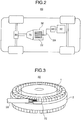
- FIG 2 is a view illustrating a structure of the electric vehicle as one example of using the electric motor 30.
- An electric vehicle 40 is mounted with the electric motor 30, and the electric motor 30 is connected to a battery 50 via an electric power converter 60 by the lead wire 20 and supplied with high-voltage DC power.
- the obtained rotation torque based on the electric motor 30 is transmitted to a transmission 70 and a gear 80 to play a role to drive the electric vehicle.
- the connecting method of this embodiment is largely comprised of two steps. That is, they are a first step of hardening the twisted wire 20 and a second step of bonding the hardened twisted wire 20 and the wire material 22.
- a processing method of the wire material in this embodiment has the first step to harden the twisted wire and the second step to connect the hardened twisted wire and the wire material.
- FIG 1(a) is a front view after the twisted wire was hardened in the first step
- (b) is a sectional view taken along A-A' section of (a)
- FIG 1(c) is a front view after the twisted wire hardened in the second step and the wire material were bonded
- (d) is a sectional view taken along B-B' section of (c).
- a twisted wire 21 becomes a twisted wire 21' by being applied with ultrasonic vibration from a top surface by a vibration tool 11 so as to be hardened from a substantially circular cross-sectional shape into a rectangular shape same as that of the groove of an anvil 12.
- the wire material 22 is placed on a bottom surface 13 of the groove formed in the anvil 12, the twisted wire 21' hardened in the first step is reversed from the state of FIG 1(a) and (b) , placed on the wire material 22, and applied with ultrasonic vibration from the top surface by the vibration tool 11 to become a twisted wire 21".
- FIG 4 is views for explaining in detail the procedure of hardening the twisted wire as the first step in the connecting step.
- the twisted wire 21 having a substantially circular cross section in FIG 4(a) and (b) is placed on the bottom surface 13 of the groove formed in the anvil 12 so as to be held between it and the vibration tool 11.
- the ultrasonic vibration is applied from the vibration tool 11 to the twisted wire 21 while applying a predetermined pressurizing force as shown in FIG 4(c) and (d)
- core wires on the top surface of the twisted wire 21, namely on a bonding surface 24 side are mutually bonded to become the twisted wire 21' hardened along the groove shape of the anvil 12.
- a pressurizing surface of the vibration tool 11 has a substantially flat surface in order to fit the shape of the twisted wire 21 to the shape of the bonding surface of the wire material 22.
- the pressurizing surface of the vibration tool 11 has a later-described minute irregular shape for propagation of ultrasonic waves, but the substantially flat surface means that a basic shape excluding the minute irregular shape is a flat surface.
- the shape of the groove of the anvil 12 is determined to be rectangular in order to apply evenly a pressure to the twisted wire 21.
- FIG 5 is views explaining in detail a procedure in bonding the hardened twisted wire and the wire material in the second step of the connecting step.
- the twisted wire 21' hardened in FIG 4(c) and (d) is axially reversed as shown in FIG 5(a) and (b) and placed on the wire material 22, which is placed on the bottom surface 13 of the groove formed in the anvil 12 and has substantially the same cross section as that of the groove of the anvil 12, and ultrasonic vibration is applied to the twisted wire 21' by applying a predetermined pressurizing force by the vibration tool 11 from above in FIG 5(a) and (b) .
- the twisted wire 21" is additionally hardened its top surface and diffusion bonded to the top surface of the wire material 22 with the bonding surface 24 on the under surface of the twisted wire.
- the twisted wire 21' becomes the twisted wire 21" as the core wires on the vibration tool 11 side are bonded mutually and additionally hardened, and an interfacial diffusion reaction is caused on the bonding surface 24 of the twisted wire 21" and the top surface of the wire material 22 so as to bond, thereby obtaining connection of the wire material 22 and the twisted wire 21".
- the vibration tool 11 and the anvil 12 are formed to harden the twisted wire 12 into a vertically symmetrical rectangular shape, the same vibration tool 11 and anvil 12 can be used in the first step and the second step, but not only the above, different vibration tool 11 and anvil 12 may be used depending on the circumstance of the facilities.
- the bonding of the twisted wire and the wire material obtained in the above-described two steps allows direct bonding without using the connecting member, there can be obtained the connected portion having a size same as or not larger than the cross-sectional area of the twisted wire and the wire material before connection.
- FIG 6 is views showing a change of the cross-sectional shape of the twisted wire in the first and second connecting steps.
- FIG 6(a) is a sectional view when the twisted wire 21 was hardened to become the twisted wire 21' in the first step.
- the top surface of the twisted wire 21' which is the side applied with ultrasonic vibration by the vibration tool 11 has the core wires mutually bonded and hardened densely, but since the under surface of the twisted wire 21' on the anvil 12 side does not receive propagation of ultrasonic vibration, the core wires are mutually bonded sparsely or not bonded.
- FIG. 6(b) is a sectional view when the twisted wire 21" and the wire material 22 are bonded in the second step.
- the top surface of the twisted wire of FIG 6(b) namely the surface on the side opposite to the bonding surface 24 of the twisted wire, has unification of the core wires advanced similar to the bonding surface 24, but its middle portion has a portion 25 where the core wires have not been unified (small bonding).
- a binding force of the core wires is low and vibration is caused easily, so that ultrasonic vibration can be propagated without attenuating as in the solid.
- the portion 25 where the core wires are not unified acts as an ultrasonic wave transmission layer if thickness Da and Db of the unified part of the twisted wire are smaller than the propagation distance, and there can be obtained ultrasonic bonding between the bonding surface 24 of the twisted wire 21" and the top surface of the wire material 22. Since the core wires are partly unified in the twisted wire 21" bonded with the wire material 22, an apparent cross-sectional area obtained from an overall breadth B and the thickness D of the twisted wire inevitably becomes smaller than the overall cross-sectional area of the twisted wire before hardening.
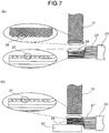
- FIG 7 is views showing a change in appearance of the twisted wire surface in the connecting step.
- FIG. 7(a) is a side view after the hardened twisted wire 21' was formed by applying ultrasonic vibration to the twisted wire 21 by the vibration tool 11 in the first step.
- An under surface of the vibration tool 11 is provided with an irregular shape 26 for catching a bonding member so as to facilitate the propagation of the ultrasonic waves.
- the twisted wire 21' which was hardened by application of ultrasonic vibration has impressions 27, which are transcribed irregular shapes, remained on the surface contacted with the vibration tool 11.
- the irregular shape 26 has quadrangular pyramids arranged in a net-like appearance but its shape can be changed to a net-like arrangement of square pillars or a ridge-and-root arrangement in the axial direction of the twisted wire as long as the bonding member can be caught.
- FIG 7(b) is a side view after the twisted wire 21' and the wire material 22 were bonded in the second step.
- the twisted wire 21" hardened in the second step also has the impressions 27 having the irregular shape remained on the surface on the opposite side of the bonding surface 24. Therefore, the twisted wire 21" has a feature that it has the irregular shape on the bonding surface 24 and its opposite face.
- the ultrasonic vibration is applied from the vibration tool 11 to the twisted wire 21, the hardened twisted wire 21' is reversed and ultrasonic bonded with the wire material 22, so that the portion 25 where the core wires are not unified acts as the ultrasonic wave transmission layer, and connection having sufficient bonding strength can be obtained in connecting the twisted wire and the wire material having a large wire diameter.
- a second embodiment of the present invention is described with reference to FIG 8 and FIG 9 .
- FIG 8 is another embodiment explaining the first step in the connecting step described in the first embodiment, FIG 8 (b) shows a case that a vibration tool not having a curved surface on its end surface was used, and FIG 8 (a) shows a case that a vibration tool having one curved surface on its end surface was used.
- disconnection 28 occurs in the core wires of the twisted wire 21 if the twisted wire 21' has a large deformation amount T.
- the disconnection of the core wires generates resistance at the passage of electric current and must be prevented because it becomes a cause of generating heat in the disconnection portion and creates an adverse effect on the peripheral members.
- the vibration tool 11 in FIG 8 (a) has a feature that a curved surface Ra is formed on the end portion of the under surface.
- this vibration tool 11 is used to harden the twisted wire 21 by ultrasonic bonding, the core wires are not broken even if the twisted wire 21' had a large deformation amount T. And, an effect of preventing the wire breaking can be further obtained when a curvature radius of the curved surface Ra is determined to be same to or not smaller than the deformation amount T of the twisted wire 21'.
- a copper twisted wire which has an overall diameter of 5 mm, a core wire diameter of 0.4 mm, and a core wire number of 80 is hardened to have a rectangular cross-sectional shape having a breadth of 3.5 mm and a thickness of 3 mm
- the core wires of the twisted wire were broken when the vibration tool 11 was not formed with the curved surface, but when a curved surface having a curvature radius of 2 mm was formed on the end portion of the under surface of the vibration tool 11, there was obtained an effect that the core wires of the twisted wire were not broken.
- FIG. 9 is another embodiment explaining the first step in the connecting step described in the first embodiment and shows a case using a vibration tool which is formed with stepped portions comprising three curved surfaces including one curved surface at the end surface.
- the vibration tool 11 in FIG 9 has a feature that a stepped portion 29 was formed on the under surface.
- the portion pressurized by the stepped portion 29 has the pressurizing force and the deformation amount T decreased, so that there is provided an effect of preventing wire breaking.
- an effect of preventing the wire breaking can be further obtained by setting a height of the stepped portion 29 to a level same as or not larger than the diameter of core wires of the twisted wire 21 and forming curved surfaces Ra, Rb, Rc on an end portion of the stepped portion 29.
- FIG 9 an example of the vibration tool 11 formed with the stepped portion comprising three curved surfaces was explained, but the same effect can also be obtained by disposing more stepped portions.
- the core wires can be prevented from breaking when a twisted wire having a large wire diameter is hardened.
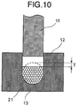
- FIG 10 is another embodiment explaining the first step in the connecting step explained in the first embodiment and shows a case using an anvil having the bottom surface of the groove formed into a round shape.
- the anvil 12 in FIG 10 has a feature that the bottom surface 13 of the groove is a curved surface having a curvature radius which is substantially same as the cross-sectional shape of the twisted wire 21 before it was hardened, and when the twisted wire 21 is hardened by ultrasonic bonding, the core wires below the twisted wire 21 are restrained from moving, a deformation amount T of the twisted wire 21' becomes small, and the core wires can be prevented from breaking.
- the connected portion is caused to vibrate due to vibration caused when the electric motor or the generator is used and has a possibility of colliding with another member to damage it, but there can also be obtained an effect that no damage might be caused even if it collides with another member by connecting the twisted wire, which has its cross-sectional shape hardened partly to have the curved surface, with the wire material.
- the present invention was specifically explained above based on the embodiments, but it is also possible to use in combination the above types of inventions separately explained above. And, the case that the cross-sectional shape of the twisted wire was circular before it was hardened was explained as an example, but even when the twisted wire has another cross-sectional shape, a similar effect can be obtained by forming the shape of the bottom surface of the groove to have substantially the same shape as the cross-sectional shape of the twisted wire before hardening. That is, it is needless to say that the present invention is not limited to the above-described embodiments of the present invention and various modifications can be made within the scope of the present invention in ultrasonic bonding of the twisted wire and the wire material as defined by the appended claims.
Landscapes
- Engineering & Computer Science (AREA)
- Manufacturing & Machinery (AREA)
- Power Engineering (AREA)
- Mechanical Engineering (AREA)
- Pressure Welding/Diffusion-Bonding (AREA)
- Manufacturing Of Electrical Connectors (AREA)
- Cable Accessories (AREA)
- Windings For Motors And Generators (AREA)
Description
- The present invention relates to a method for connecting a wire material, and to an electric motor or a generator using it.
- The electric motor and the generator represented by a motor or an alternator have a single wire of copper, whose electric resistance is low, wound as a wire material around the core of a rotor or a stator, and generates a magnetic field by passing an electric current. The electric current passage of the electric motor and the generator with an outside power-supply unit is often performed with a twisted wire as a lead wire connected to an end of the wire material. Since the twisted wire is composed of a plurality of thin core wires, it has high flexibility and is used generally because it can be wired easily to the power-supply unit or the like.
- As a method for connecting the end of this wire material and the twisted wire, there is a method using a caulking terminal. The wire material is connected to one end of the caulking terminal having a caulking part at both ends, and the twisted wire is connected to the other end by caulking. Therefore, there is an advantage that a connection work can be performed easily.
- But, the caulking terminal has a disadvantage that the connected portion becomes large because the peripheries of the wire material and the twisted wire are surrounded by the caulking member.
- In recent years, a compact and high-power electric motor such as an electric motor for a hybrid car or an electric car is demanded to be made compact including the connected portion of the wire material.
- As another connecting method used instead of the caulking terminal, ultrasonic bonding is available. The ultrasonic bonding is a bonding method which uses a device comprising a vibration tool for ultrasonic oscillation and an anvil for fixing a member, holds the member between the vibration tool and the anvil, and applies ultrasonic vibration while pressurizing to cause a diffusion reaction on the interface between two bonding members. Since the ultrasonic bonding does not need to use an additional member such as the caulking terminal, it is effective to make the connected portion compact and to save a space.
- A method for ultrasonic bonding of a twisted wire with another member is disclosed in
Patent Literature 1. It shows that the twisted wire is previously hardened by ultrasonic bonding, and the hardened twisted wire and another connecting member are additionally bonded by ultrasonic waves. As another bonding member, a connection terminal is disclosed in its embodiments. -
- PATENT LITERATURE 1: Japanese Patent Laid-Open No.
2004-95293 - PATENT LITERATURE 2:
JP 54 043588 A - PATENT LITERATURE 3:
JP S59 165937 A - The above-described method of
Patent Literature 1, however, is hardly applicable to a high-power electric motor and generator which pass large current to the wire material. In other words, it is difficult to harden the whole twisted wire by ultrasonic bonding because the twisted wire as a lead wire has a large diameter. - Generally, there is a correlation between an ultrasonic frequency and a propagation distance of ultrasonic vibration in the ultrasonic bonding, and the propagation distance is said to be about 2 mm even by vibration at 20 KHz when the propagation distance of ultrasonic vibration is longest. When an overall diameter of the twisted wire is large and a hardened thickness is larger than the above-described propagation distance, the vibration tool side to which ultrasonic vibration is applied is hardened, but the twisted wire is not fully hardened on its opposite side, and the core wires remain as they are.
Patent Literature 1 does not disclose a method of dealing with the above case. - Here, if a diameter (thickness) of the wire material wound on the core is smaller than the above described propagation distance, bonding can be made by applying ultrasonic vibration from the wire material side. But, since the wire material has a large diameter in the high-power electric motor and generator, the ultrasonic vibration does not propagate to the interface between the twisted wire and the wire material even if the ultrasonic vibration is applied from the wire material side, and bonding cannot be made.
- The present invention has been achieved in view of the circumstances described above and aims to provide a wire material connecting method for directly bonding the wire material and the twisted wire having a large diameter of the electric motor and the generator by ultrasonic bonding, and a compact, high-power electric motor and generator which have the wire material and the twisted wire connected by the above connecting method.
- To solve the above-described problems, according to the present invention a method for connecting the twisted wire according to
claim 1 having a plurality of core wires and the wire material, performs connection including a first step that the twisted wire is hardened by ultrasonic vibration using a pressurized vibration tool, and a second step that the twisted wire and the wire material are connected by applying ultrasonic waves in the state that the surface of the twisted wire hardened by pressurizing with the vibration tool is contacted to the wire material, and a stator according to claim 7 are proposed. Dependent claims relate to preferred embodiments of the present invention. - According to the present invention, connection having sufficient bonding strength and a small connected portion can be obtained by a method for connecting a wire material for direct bonding by ultrasonic bonding of the wire material and the twisted wire having a large wire diameter of a high-power electric motor and generator.
-
-
Fig. 1 shows views for explaining a method for connecting as a first embodiment of the present invention, in which (a) is a front view after the twisted wire is hardened, (b) is a sectional view taken along A-A' section of (a), (c) is a front view after the twisted wire and the wire material are connected, and (d) is a sectional view taken along B-B' section of (c). -
Fig. 2 is a schematic view of an electric vehicle provided with the electric motor according to an embodiment of the present invention. -
Fig. 3 is a view showing a structure of the electric motor according to the embodiment of the present invention. -
Fig. 4 shows views for explaining a detailed procedure of hardening the twisted wire as a first step in the method for connecting as the first embodiment of the present invention, wherein (a) is a front view when the twisted wire is placed on an anvil, (b) is a sectional view taken along A-A' section of (a), (c) is a front view after the twisted wire is hardened, and (d) is a sectional view taken along B-B' section of (c). -
Fig. 5 shows Views for explaining a detailed procedure of connecting the twisted wire and the wire material as a second step in the method for connecting according to the first embodiment of the present invention, wherein (a) is a front view when the wire material is placed on the anvil and the twisted wire is placed on the wire material, (b) is a sectional view taken along A-A' section of (a), (c) is a front view after the twisted wire and the wire material are connected, and (d) is a sectional view taken along B-B' section of (c). -
Fig. 6 shows views for explaining a method for connecting according to the first embodiment of the present invention, wherein (a) is a sectional view after the twisted wire is hardened, and (b) is a sectional view after the twisted wire and the wire material are bonded. -
Fig. 7 shows views for explaining a method for connecting according to the first embodiment of the present invention, wherein (a) is a side view after hardening the twisted wire and an enlarged view of a bottom surface of the vibration tool and a top surface of the twisted wire, and (b) is a side view after the twisted wire and the wire material are bonded and an enlarged view of the top surface of the twisted wire. -
Fig. 8 shows views for illustrating a method for connecting according to a second embodiment of the present invention, wherein (a) shows the vibration tool with its end surface provided with a curved surface, and (b) shows the vibration tool with its end surface not provided with a curved surface. -
Fig. 9 is a view for illustrating a method for connecting according to the second embodiment of the present invention, showing a plurality of curved surfaces formed on the bottom surface of the vibration tool. -
Fig. 10 is a view for illustrating a method for connecting according to a third embodiment of the present invention, wherein (a) shows an anvil with a curved surface formed on its bottom surface, and (b) shows an anvil having a flat bottom surface. - Examples of the embodiments of the present invention are described below with reference to the drawings.
- One embodiment of the method for connecting the wire material of the present invention is described using
FIG 1 to FIG 6 . -
FIG. 3 is a view illustrating a structure of anelectric motor 30 according to one embodiment of the present invention. Theelectric motor 30 has arotor 1, astator core 2, and awire material 22 wound on thestator core 2. Alead wire 20 is connected to an end of thewire material 22 to pass electric current to theelectric motor 30. Thewire material 22 is a single metallic wire, but for thelead wire 20, there is commonly used a twisted wire which allows the passage of large electric current and can have high flexibility so that it can be wired easily even if its diameter is large. The twisted wire is formed by twisting a plurality of core wires. Thelead wire 20 represented by the twisted wire and thewire material 22 are desirably connected without using another bonding member in view of electric resistance and dimensions of the connected portion. -
FIG 2 is a view illustrating a structure of the electric vehicle as one example of using theelectric motor 30. Anelectric vehicle 40 is mounted with theelectric motor 30, and theelectric motor 30 is connected to abattery 50 via anelectric power converter 60 by thelead wire 20 and supplied with high-voltage DC power. Thus, the obtained rotation torque based on theelectric motor 30 is transmitted to atransmission 70 and agear 80 to play a role to drive the electric vehicle. - A method of connecting the
lead wire 20 and thewire material 22 is described. The connecting method of this embodiment is largely comprised of two steps. That is, they are a first step of hardening thetwisted wire 20 and a second step of bonding the hardenedtwisted wire 20 and thewire material 22. - A processing method of the wire material in this embodiment has the first step to harden the twisted wire and the second step to connect the hardened twisted wire and the wire material.
FIG 1(a) is a front view after the twisted wire was hardened in the first step, (b) is a sectional view taken along A-A' section of (a),FIG 1(c) is a front view after the twisted wire hardened in the second step and the wire material were bonded, and (d) is a sectional view taken along B-B' section of (c). - In the first step, a
twisted wire 21 becomes a twisted wire 21' by being applied with ultrasonic vibration from a top surface by avibration tool 11 so as to be hardened from a substantially circular cross-sectional shape into a rectangular shape same as that of the groove of ananvil 12. In the second step, thewire material 22 is placed on abottom surface 13 of the groove formed in theanvil 12, the twisted wire 21' hardened in the first step is reversed from the state ofFIG 1(a) and (b) , placed on thewire material 22, and applied with ultrasonic vibration from the top surface by thevibration tool 11 to become atwisted wire 21". -
FIG 4 is views for explaining in detail the procedure of hardening the twisted wire as the first step in the connecting step. In the first step, thetwisted wire 21 having a substantially circular cross section inFIG 4(a) and (b) is placed on thebottom surface 13 of the groove formed in theanvil 12 so as to be held between it and thevibration tool 11. Then, when the ultrasonic vibration is applied from thevibration tool 11 to the twistedwire 21 while applying a predetermined pressurizing force as shown inFIG 4(c) and (d) , core wires on the top surface of the twistedwire 21, namely on abonding surface 24 side, are mutually bonded to become the twisted wire 21' hardened along the groove shape of theanvil 12. In this embodiment, a pressurizing surface of thevibration tool 11 has a substantially flat surface in order to fit the shape of the twistedwire 21 to the shape of the bonding surface of thewire material 22. Here, the pressurizing surface of thevibration tool 11 has a later-described minute irregular shape for propagation of ultrasonic waves, but the substantially flat surface means that a basic shape excluding the minute irregular shape is a flat surface. And, the shape of the groove of theanvil 12 is determined to be rectangular in order to apply evenly a pressure to the twistedwire 21. -
FIG 5 is views explaining in detail a procedure in bonding the hardened twisted wire and the wire material in the second step of the connecting step. In the second step, the twisted wire 21' hardened inFIG 4(c) and (d) is axially reversed as shown inFIG 5(a) and (b) and placed on thewire material 22, which is placed on thebottom surface 13 of the groove formed in theanvil 12 and has substantially the same cross section as that of the groove of theanvil 12, and ultrasonic vibration is applied to the twisted wire 21' by applying a predetermined pressurizing force by thevibration tool 11 from above inFIG 5(a) and (b) . Thetwisted wire 21" is additionally hardened its top surface and diffusion bonded to the top surface of thewire material 22 with thebonding surface 24 on the under surface of the twisted wire. As a result, as shown inFIG 5(c) and (d) , the twisted wire 21' becomes thetwisted wire 21" as the core wires on thevibration tool 11 side are bonded mutually and additionally hardened, and an interfacial diffusion reaction is caused on thebonding surface 24 of the twistedwire 21" and the top surface of thewire material 22 so as to bond, thereby obtaining connection of thewire material 22 and thetwisted wire 21". In this embodiment, since thevibration tool 11 and theanvil 12 are formed to harden the twistedwire 12 into a vertically symmetrical rectangular shape, thesame vibration tool 11 andanvil 12 can be used in the first step and the second step, but not only the above,different vibration tool 11 andanvil 12 may be used depending on the circumstance of the facilities. - Since the bonding of the twisted wire and the wire material obtained in the above-described two steps allows direct bonding without using the connecting member, there can be obtained the connected portion having a size same as or not larger than the cross-sectional area of the twisted wire and the wire material before connection.
-
FIG 6 is views showing a change of the cross-sectional shape of the twisted wire in the first and second connecting steps.FIG 6(a) is a sectional view when thetwisted wire 21 was hardened to become the twisted wire 21' in the first step. The top surface of the twisted wire 21' which is the side applied with ultrasonic vibration by thevibration tool 11 has the core wires mutually bonded and hardened densely, but since the under surface of the twisted wire 21' on theanvil 12 side does not receive propagation of ultrasonic vibration, the core wires are mutually bonded sparsely or not bonded. -
FIG. 6(b) is a sectional view when thetwisted wire 21" and thewire material 22 are bonded in the second step. The top surface of the twisted wire ofFIG 6(b) , namely the surface on the side opposite to thebonding surface 24 of the twisted wire, has unification of the core wires advanced similar to thebonding surface 24, but its middle portion has aportion 25 where the core wires have not been unified (small bonding). In theportion 25 where the core wires have not been unified, a binding force of the core wires is low and vibration is caused easily, so that ultrasonic vibration can be propagated without attenuating as in the solid. Thus, even if an overall thickness D of the twistedwire 21" is larger than the propagation distance of ultrasonic waves, theportion 25 where the core wires are not unified acts as an ultrasonic wave transmission layer if thickness Da and Db of the unified part of the twisted wire are smaller than the propagation distance, and there can be obtained ultrasonic bonding between thebonding surface 24 of the twistedwire 21" and the top surface of thewire material 22. Since the core wires are partly unified in the twistedwire 21" bonded with thewire material 22, an apparent cross-sectional area obtained from an overall breadth B and the thickness D of the twisted wire inevitably becomes smaller than the overall cross-sectional area of the twisted wire before hardening. -
FIG 7 is views showing a change in appearance of the twisted wire surface in the connecting step.FIG. 7(a) is a side view after the hardened twisted wire 21' was formed by applying ultrasonic vibration to the twistedwire 21 by thevibration tool 11 in the first step. An under surface of thevibration tool 11 is provided with anirregular shape 26 for catching a bonding member so as to facilitate the propagation of the ultrasonic waves. The twisted wire 21' which was hardened by application of ultrasonic vibration hasimpressions 27, which are transcribed irregular shapes, remained on the surface contacted with thevibration tool 11. It is determined in this embodiment that theirregular shape 26 has quadrangular pyramids arranged in a net-like appearance but its shape can be changed to a net-like arrangement of square pillars or a ridge-and-root arrangement in the axial direction of the twisted wire as long as the bonding member can be caught. -
FIG 7(b) is a side view after the twisted wire 21' and thewire material 22 were bonded in the second step. Thetwisted wire 21" hardened in the second step also has theimpressions 27 having the irregular shape remained on the surface on the opposite side of thebonding surface 24. Therefore, thetwisted wire 21" has a feature that it has the irregular shape on thebonding surface 24 and its opposite face. - According to the above-described first embodiment, the ultrasonic vibration is applied from the
vibration tool 11 to the twistedwire 21, the hardened twisted wire 21' is reversed and ultrasonic bonded with thewire material 22, so that theportion 25 where the core wires are not unified acts as the ultrasonic wave transmission layer, and connection having sufficient bonding strength can be obtained in connecting the twisted wire and the wire material having a large wire diameter. - For example, when an ultrasonic bonding machine having an ultrasonic frequency of 20 kHz and a vibration tool tip-end area of 40 mm2 was used to connect a twisted wire having an overall diameter of 5 mm which comprises copper core wires having a diameter of 0.4 mm and a number of 80 and a wire material which is a copper square wire having a cross-sectional shape with a breadth of 4 mm and a thickness of 3 mm, there was obtained connection with a sufficient bonding strength of about 1500N.
- A second embodiment of the present invention is described with reference to
FIG 8 and FIG 9 . -
FIG 8 is another embodiment explaining the first step in the connecting step described in the first embodiment,FIG 8 (b) shows a case that a vibration tool not having a curved surface on its end surface was used, andFIG 8 (a) shows a case that a vibration tool having one curved surface on its end surface was used. - When the curved surface is not provided but a corner is provided around the end portion of the
vibration tool 11 as inFIG 8 (b) ,disconnection 28 occurs in the core wires of the twistedwire 21 if the twisted wire 21' has a large deformation amount T. The disconnection of the core wires generates resistance at the passage of electric current and must be prevented because it becomes a cause of generating heat in the disconnection portion and creates an adverse effect on the peripheral members. - On the other hand, the
vibration tool 11 inFIG 8 (a) has a feature that a curved surface Ra is formed on the end portion of the under surface. When thisvibration tool 11 is used to harden the twistedwire 21 by ultrasonic bonding, the core wires are not broken even if the twisted wire 21' had a large deformation amount T. And, an effect of preventing the wire breaking can be further obtained when a curvature radius of the curved surface Ra is determined to be same to or not smaller than the deformation amount T of the twisted wire 21'. - For example, in a case where a copper twisted wire which has an overall diameter of 5 mm, a core wire diameter of 0.4 mm, and a core wire number of 80 is hardened to have a rectangular cross-sectional shape having a breadth of 3.5 mm and a thickness of 3 mm, the core wires of the twisted wire were broken when the
vibration tool 11 was not formed with the curved surface, but when a curved surface having a curvature radius of 2 mm was formed on the end portion of the under surface of thevibration tool 11, there was obtained an effect that the core wires of the twisted wire were not broken. -
FIG. 9 is another embodiment explaining the first step in the connecting step described in the first embodiment and shows a case using a vibration tool which is formed with stepped portions comprising three curved surfaces including one curved surface at the end surface. - The
vibration tool 11 inFIG 9 has a feature that a steppedportion 29 was formed on the under surface. In the twisted wire 21' hardened by thevibration tool 11, the portion pressurized by the steppedportion 29 has the pressurizing force and the deformation amount T decreased, so that there is provided an effect of preventing wire breaking. And, in a case where the steppedportion 29 is formed on the under surface of thevibration tool 11, an effect of preventing the wire breaking can be further obtained by setting a height of the steppedportion 29 to a level same as or not larger than the diameter
of core wires of the twistedwire 21 and forming curved surfaces Ra, Rb, Rc on an end portion of the steppedportion 29. InFIG 9 , an example of thevibration tool 11 formed with the stepped portion comprising three curved surfaces was explained, but the same effect can also be obtained by disposing more stepped portions. - According to the above-explained second embodiment, by forming the curved surface on a part of the under surface of the
vibration tool 11, the core wires can be prevented from breaking when a twisted wire having a large wire diameter is hardened. - A third embodiment of the present invention is explained with reference to
FIG 10. FIG 10 is another embodiment explaining the first step in the connecting step explained in the first embodiment and shows a case using an anvil having the bottom surface of the groove formed into a round shape. - The
anvil 12 inFIG 10 has a feature that thebottom surface 13 of the groove is a curved surface having a curvature radius which is substantially same as the cross-sectional shape of the twistedwire 21 before it was hardened, and when thetwisted wire 21 is hardened by ultrasonic bonding, the core wires below the twistedwire 21 are restrained from moving, a deformation amount T of the twisted wire 21' becomes small, and the core wires can be prevented from breaking. - For example, when copper twisted wires having an overall diameter of 5 mm, a core wire diameter 0.4 mm and a core wire number of 80 were hardened and the bottom surface of the groove was formed into a rectangular shape having a breadth of 5 mm, core wires were broken. But, when the bottom surface of the groove was formed to have a curvature radius of 2.5 mm, the deformation amount of the twisted wire became about 1/2 time, and there was obtained an effect that the core wires of the twisted wire were not broken.
- In addition, the connected portion is caused to vibrate due to vibration caused when the electric motor or the generator is used and has a possibility of colliding with another member to damage it, but there can also be obtained an effect that no damage might be caused even if it collides with another member by connecting the twisted wire, which has its cross-sectional shape hardened partly to have the curved surface, with the wire material.
- The present invention was specifically explained above based on the embodiments, but it is also possible to use in combination the above types of inventions separately explained above. And, the case that the cross-sectional shape of the twisted wire was circular before it was hardened was explained as an example, but even when the twisted wire has another cross-sectional shape, a similar effect can be obtained by forming the shape of the bottom surface of the groove to have substantially the same shape as the cross-sectional shape of the twisted wire before hardening. That is, it is needless to say that the present invention is not limited to the above-described embodiments of the present invention and various modifications can be made within the scope of the present invention in ultrasonic bonding of the twisted wire and the wire material as defined by the appended claims.
- 1: Rotor, 2: stator core, 11: vibration tool, 12: anvil, 13: bottom surface of groove in anvil where a bonding member is placed, 20: lead wire, 21: twisted wire, 22: wire material, 23: coating, 24: bonding surface, 25: part of twisted wire where core wires are not unified, 26: irregular shape formed on under surface of vibration tool, 27: impressions, 28: breakage of core wires, 29: stepped portion on under surface of vibration tool, 30: electric motor, 40: electric vehicle, 50: battery, 60: electric power converter, 70: transmission, 80: gear, D: overall breadth of twisted wire after applying ultrasonic waves, D: overall thickness of twisted wire after applying ultrasonic waves, Da: thickness of part where core wires of twisted wire are unified, Db: thickness of part where core wires of twisted wire are unified, Ra: curved surface of end portion of vibration tool under surface, Rb: curved surface of under surface of vibration tool, Rc: curved surface of under surface of vibration tool, T: deformation amount in thickness direction of twisted wire when the twisted wire was hardened.
Claims (7)
- A method for connecting a twisted wire (21), formed by twisting a plurality of core wires, and a wire material (22), characterised by:- a first step of hardening the twisted wire (21) by applying ultrasonic vibration from a top surface thereof using a pressurized vibration tool (11), and- a second step of directly bonding the twisted wire (21) having been hardened and the wire material by applying ultrasonic waves with the surface of the twisted wire (21), contacted in the first step with the vibration tool (11), kept in contact with the wire material, wherein, in the second step, ultrasonic waves are applied to the opposite side of the hardened surface of the twisted wire (21) by pressuring with the vibration tool (11), wherein the first step and the second step use the same vibration tool (11), and the twisted wire (21) is reversed after the first step but before the second step; and such that the twisted wire, on a cross section connected to the wire material, has a plurality of core wires configuring the twisted wire bonded and hardened on a first face which is connected to the wire material and a second face which is on the opposite side and which has a unification of the core wires similar to that of the first face, and the core wires in a region between the first face and the second face have not been unified, wherein a binding force of the core wires in the region between the first face and the second face is lower than on the first face and the second face.
- The connecting method according to claim 1, wherein:the surface of the vibration tool (11) pressurized to the twisted wire (21) in the first step is a substantially flat surface, anda portion of the wire material connected to the twisted wire (21) is a substantially flat surface.
- The connecting method according to any of claims 1 to 2, wherein: the vibration tool (11) used in the first step has a curved surface formed on the end portion of the under surface which contacts the twisted wire (21).
- The connecting method according to any of claims 1 to 2, wherein: the vibration tool (11) used in the first step a stepped portion (29) formed on the under surface which contacts the twisted wire (21).
- The connecting method according to any of claims 1 to 4, wherein:the first step is performed with the twisted wire (21) held between the vibration tool (11) and an anvil, anda portion of the anvil for sandwiching the twisted wire (21) has a rectangular shape.
- The connecting method according to any of claims 1 to 4, wherein:the first step is performed with the twisted wire (21) held between the vibration tool (11) and an anvil, andthe portion of the anvil for sandwiching the twisted wire (21) has a round shape or an oval shape.
- A stator for an electric motor (30) or a generator, comprising:- a stator core,- a wire material (22) wound on the stator core, and- a twisted wire (21), formed by twisting a plurality of core wires, directly bonded to the wire material in order to electrically connect the wire material to the outside, characterized in that: the twisted wire (21), on a cross section connected to the wire material, has the plurality of core wires configuring the twisted wire (21) bonded and hardened on a first face which is connected to the wire material and a second face which is on the opposite side and which has a unification of the core wires similar to that of the first face, and the core wires in a region between the first face and the second face have not been unified, wherein a binding force of the core wires in the region between the first face and the second face is lower than on the first face and the second face.
Applications Claiming Priority (2)
| Application Number | Priority Date | Filing Date | Title |
|---|---|---|---|
| JP2010275242A JP5393644B2 (en) | 2010-12-10 | 2010-12-10 | Connection method of wire rod and stranded wire and stator of electric motor or generator |
| PCT/JP2011/006305 WO2012077281A1 (en) | 2010-12-10 | 2011-11-11 | Method for connecting wire material and twisted wire, and stator of electric motor or generator |
Publications (3)
| Publication Number | Publication Date |
|---|---|
| EP2650984A1 EP2650984A1 (en) | 2013-10-16 |
| EP2650984A4 EP2650984A4 (en) | 2016-03-16 |
| EP2650984B1 true EP2650984B1 (en) | 2019-06-26 |
Family
ID=46206797
Family Applications (1)
| Application Number | Title | Priority Date | Filing Date |
|---|---|---|---|
| EP11847473.3A Active EP2650984B1 (en) | 2010-12-10 | 2011-11-11 | Method for connecting wire material and twisted wire, and stator of electric motor or generator |
Country Status (5)
| Country | Link |
|---|---|
| US (1) | US9419490B2 (en) |
| EP (1) | EP2650984B1 (en) |
| JP (1) | JP5393644B2 (en) |
| CN (1) | CN103299493B (en) |
| WO (1) | WO2012077281A1 (en) |
Families Citing this family (24)
| Publication number | Priority date | Publication date | Assignee | Title |
|---|---|---|---|---|
| JP5913851B2 (en) * | 2011-07-20 | 2016-04-27 | 矢崎総業株式会社 | Wire connection method |
| JP5781410B2 (en) * | 2011-09-26 | 2015-09-24 | 矢崎総業株式会社 | Connection method of single core wire and stranded wire |
| JP6116986B2 (en) * | 2013-04-17 | 2017-04-19 | 矢崎総業株式会社 | Wire connection structure and connection method |
| US20140374466A1 (en) * | 2013-06-19 | 2014-12-25 | Branson Ultrasonics Corporation | Method of ultrasonically welding multi-stranded malleable wires together |
| DE102013107637A1 (en) | 2013-07-18 | 2015-01-22 | Schunk Sonosystems Gmbh | Method for producing a knot by welding |
| US9560729B2 (en) * | 2013-09-09 | 2017-01-31 | Cutsforth, Inc. | Grounding rope for a shaft grounding apparatus of a dynamo-electric machine |
| DE112015001994A5 (en) | 2014-04-25 | 2017-01-26 | Brusa Elektronik Ag | Formed wire, its use, as well as method for producing a stator for an electric machine |
| CN105390905B (en) * | 2014-09-03 | 2018-07-27 | 矢崎总业株式会社 | Cover the joint method of skin electric wire |
| JP2017152224A (en) * | 2016-02-25 | 2017-08-31 | 住友電装株式会社 | Bonded article made of core wire and bonding object, terminal, ultrasonic bonding device, and method of bonding between core wire and bonding object |
| JP6646872B2 (en) * | 2016-03-09 | 2020-02-14 | 株式会社オートネットワーク技術研究所 | Manufacturing method of electric wire with terminal and electric wire with terminal |
| EP3335827B1 (en) * | 2016-12-15 | 2019-10-09 | Aptiv Technologies Limited | Method to predict a strength of an ultrasonic weld-joint |
| DE102017112947A1 (en) * | 2017-06-13 | 2018-12-13 | Te Connectivity Germany Gmbh | High current electrical connector and method of making a high current electrical connector |
| JP6887203B2 (en) * | 2017-07-14 | 2021-06-16 | 古河電気工業株式会社 | Conductor connection device and conductor connection method |
| DE102017125887A1 (en) | 2017-11-06 | 2019-05-09 | Thyssenkrupp Ag | Method and device for producing strands, strand and electrical machine |
| JP6785210B2 (en) * | 2017-11-28 | 2020-11-18 | 矢崎総業株式会社 | Ultrasonic bonding method for electric wire conductors, manufacturing method for electric wires with terminals, and ultrasonic bonding equipment |
| JP6674433B2 (en) * | 2017-11-28 | 2020-04-01 | 矢崎総業株式会社 | Manufacturing method of electric wire with terminal and electric wire with terminal |
| JP6927909B2 (en) * | 2018-03-01 | 2021-09-01 | 矢崎総業株式会社 | How to join conductors of electric wires and electric wires |
| JP2019153420A (en) * | 2018-03-01 | 2019-09-12 | 矢崎総業株式会社 | Joining method of conductor of wire and wire |
| DE102018111853A1 (en) * | 2018-03-21 | 2019-09-26 | Auto-Kabel Management Gmbh | Method for producing a connection between an electrical connection element for a motor vehicle electrical system and a cable of the motor vehicle electrical system |
| DE102018119844B4 (en) * | 2018-07-26 | 2022-10-06 | Auto-Kabel Management Gmbh | Electrical connection and method of making an electrical connection |
| EP4054786A1 (en) * | 2019-11-05 | 2022-09-14 | Schunk Sonosystems Gmbh | Ultrasonic welding device having movable stop element |
| WO2021089155A1 (en) * | 2019-11-07 | 2021-05-14 | Schunk Sonosystems Gmbh | Ultrasonic welding apparatus with cooling for oscillator arrangement |
| JP7444671B2 (en) * | 2020-03-25 | 2024-03-06 | 古河電気工業株式会社 | Conductor joining structure and conductor joining method |
| JP2024011154A (en) * | 2022-07-14 | 2024-01-25 | 住友電装株式会社 | Ultrasonic junction body |
Citations (1)
| Publication number | Priority date | Publication date | Assignee | Title |
|---|---|---|---|---|
| JPS59165937A (en) * | 1983-03-09 | 1984-09-19 | Toshiba Corp | Lead wirings of rotary electric machine |
Family Cites Families (6)
| Publication number | Priority date | Publication date | Assignee | Title |
|---|---|---|---|---|
| JPS5443588A (en) * | 1977-09-12 | 1979-04-06 | Mitsubishi Electric Corp | Jointing method of stranded copper wire |
| JP3385980B2 (en) * | 1998-10-07 | 2003-03-10 | 住友電装株式会社 | Horn of ultrasonic welding machine |
| JP2002300745A (en) * | 2001-03-30 | 2002-10-11 | Fuji Electric Co Ltd | Wire connection device for stator coil of rotary electric machine |
| JP4021734B2 (en) * | 2002-08-30 | 2007-12-12 | 矢崎総業株式会社 | Wire ultrasonic bonding method |
| WO2005021203A1 (en) * | 2003-08-22 | 2005-03-10 | Schunk Ultraschalltechnik Gmbh | Device for compacting and/or welding electric conductors |
| JP4778369B2 (en) * | 2005-07-19 | 2011-09-21 | 矢崎総業株式会社 | Wire connection method |
-
2010
- 2010-12-10 JP JP2010275242A patent/JP5393644B2/en active Active
-
2011
- 2011-11-11 WO PCT/JP2011/006305 patent/WO2012077281A1/en active Application Filing
- 2011-11-11 US US13/992,667 patent/US9419490B2/en active Active
- 2011-11-11 CN CN201180059604.8A patent/CN103299493B/en active Active
- 2011-11-11 EP EP11847473.3A patent/EP2650984B1/en active Active
Patent Citations (1)
| Publication number | Priority date | Publication date | Assignee | Title |
|---|---|---|---|---|
| JPS59165937A (en) * | 1983-03-09 | 1984-09-19 | Toshiba Corp | Lead wirings of rotary electric machine |
Also Published As
| Publication number | Publication date |
|---|---|
| CN103299493A (en) | 2013-09-11 |
| CN103299493B (en) | 2016-05-04 |
| US9419490B2 (en) | 2016-08-16 |
| EP2650984A4 (en) | 2016-03-16 |
| JP5393644B2 (en) | 2014-01-22 |
| EP2650984A1 (en) | 2013-10-16 |
| JP2012124078A (en) | 2012-06-28 |
| WO2012077281A1 (en) | 2012-06-14 |
| US20130293045A1 (en) | 2013-11-07 |
Similar Documents
| Publication | Publication Date | Title |
|---|---|---|
| EP2650984B1 (en) | Method for connecting wire material and twisted wire, and stator of electric motor or generator | |
| JP6065032B2 (en) | Laminated core manufacturing method and laminated core | |
| JP5660458B2 (en) | Electric wire with terminal and manufacturing method thereof | |
| JP2012124078A5 (en) | ||
| CN102918749B (en) | Stator structure and manufacturing method for stators | |
| EP2176027B1 (en) | Ultrasonic joining method using a flat end face of chip provided with straight grooves | |
| JP5309431B2 (en) | Laminated steel sheet of electromagnetic steel having high resistance between steel sheets on shear plane of steel sheet and caulking method thereof | |
| JP2014207827A (en) | Connection member for motor and motor device | |
| US20140312097A1 (en) | Wire connection method and wire connection device | |
| JP2011222311A (en) | Wire connection method and wire harness | |
| JP5369637B2 (en) | Electric wire with terminal fitting and method for manufacturing the same | |
| EP2897133B1 (en) | Terminal-formed wire and method for manufacturing said terminal-formed wire | |
| JP2011060778A (en) | Connection terminal and aluminum cable with the same | |
| JP5191923B2 (en) | Wire connection method | |
| JP2011014438A (en) | Electric wire connection structure, and conductive line for vehicle having the same | |
| JP2004050204A (en) | Ultrasonic welding method and cable suitable for ultrasonic welding | |
| JP5695987B2 (en) | Single core wire and terminal crimping structure of single core wire | |
| JP6316230B2 (en) | Electric wire with connection terminal and method of manufacturing the electric wire | |
| JP2011090804A (en) | Electric wire with terminal fitting and method of manufacturing the same | |
| JP2011134515A (en) | Electric wire with terminal fitting, and manufacturing method thereof | |
| JP5223798B2 (en) | Electric wire connection structure and vehicle conductive path having the electric wire connection structure | |
| JP2012164535A (en) | Connection method of wire material and strand and rotary electric machine using the same | |
| JP5802042B2 (en) | Ultrasonic bonding equipment for aluminum wires | |
| JP2013242991A (en) | Junction structure for electric wires | |
| JPH0831469A (en) | Splice part structure of electric wire |
Legal Events
| Date | Code | Title | Description |
|---|---|---|---|
| PUAI | Public reference made under article 153(3) epc to a published international application that has entered the european phase |
Free format text: ORIGINAL CODE: 0009012 |
|
| 17P | Request for examination filed |
Effective date: 20130710 |
|
| AK | Designated contracting states |
Kind code of ref document: A1 Designated state(s): AL AT BE BG CH CY CZ DE DK EE ES FI FR GB GR HR HU IE IS IT LI LT LU LV MC MK MT NL NO PL PT RO RS SE SI SK SM TR |
|
| DAX | Request for extension of the european patent (deleted) | ||
| RA4 | Supplementary search report drawn up and despatched (corrected) |
Effective date: 20160216 |
|
| RIC1 | Information provided on ipc code assigned before grant |
Ipc: H02G 1/14 20060101ALI20160210BHEP Ipc: B23K 20/10 20060101ALI20160210BHEP Ipc: H02K 3/04 20060101ALI20160210BHEP Ipc: H01R 43/02 20060101AFI20160210BHEP |
|
| STAA | Information on the status of an ep patent application or granted ep patent |
Free format text: STATUS: EXAMINATION IS IN PROGRESS |
|
| 17Q | First examination report despatched |
Effective date: 20180608 |
|
| GRAP | Despatch of communication of intention to grant a patent |
Free format text: ORIGINAL CODE: EPIDOSNIGR1 |
|
| STAA | Information on the status of an ep patent application or granted ep patent |
Free format text: STATUS: GRANT OF PATENT IS INTENDED |
|
| INTG | Intention to grant announced |
Effective date: 20190118 |
|
| GRAS | Grant fee paid |
Free format text: ORIGINAL CODE: EPIDOSNIGR3 |
|
| GRAA | (expected) grant |
Free format text: ORIGINAL CODE: 0009210 |
|
| STAA | Information on the status of an ep patent application or granted ep patent |
Free format text: STATUS: THE PATENT HAS BEEN GRANTED |
|
| AK | Designated contracting states |
Kind code of ref document: B1 Designated state(s): AL AT BE BG CH CY CZ DE DK EE ES FI FR GB GR HR HU IE IS IT LI LT LU LV MC MK MT NL NO PL PT RO RS SE SI SK SM TR |
|
| REG | Reference to a national code |
Ref country code: GB Ref legal event code: FG4D |
|
| REG | Reference to a national code |
Ref country code: CH Ref legal event code: EP |
|
| REG | Reference to a national code |
Ref country code: AT Ref legal event code: REF Ref document number: 1149389 Country of ref document: AT Kind code of ref document: T Effective date: 20190715 |
|
| REG | Reference to a national code |
Ref country code: DE Ref legal event code: R096 Ref document number: 602011060103 Country of ref document: DE |
|
| REG | Reference to a national code |
Ref country code: IE Ref legal event code: FG4D |
|
| REG | Reference to a national code |
Ref country code: NL Ref legal event code: MP Effective date: 20190626 |
|
| PG25 | Lapsed in a contracting state [announced via postgrant information from national office to epo] |
Ref country code: LT Free format text: LAPSE BECAUSE OF FAILURE TO SUBMIT A TRANSLATION OF THE DESCRIPTION OR TO PAY THE FEE WITHIN THE PRESCRIBED TIME-LIMIT Effective date: 20190626 Ref country code: SE Free format text: LAPSE BECAUSE OF FAILURE TO SUBMIT A TRANSLATION OF THE DESCRIPTION OR TO PAY THE FEE WITHIN THE PRESCRIBED TIME-LIMIT Effective date: 20190626 Ref country code: NO Free format text: LAPSE BECAUSE OF FAILURE TO SUBMIT A TRANSLATION OF THE DESCRIPTION OR TO PAY THE FEE WITHIN THE PRESCRIBED TIME-LIMIT Effective date: 20190926 Ref country code: HR Free format text: LAPSE BECAUSE OF FAILURE TO SUBMIT A TRANSLATION OF THE DESCRIPTION OR TO PAY THE FEE WITHIN THE PRESCRIBED TIME-LIMIT Effective date: 20190626 Ref country code: AL Free format text: LAPSE BECAUSE OF FAILURE TO SUBMIT A TRANSLATION OF THE DESCRIPTION OR TO PAY THE FEE WITHIN THE PRESCRIBED TIME-LIMIT Effective date: 20190626 Ref country code: FI Free format text: LAPSE BECAUSE OF FAILURE TO SUBMIT A TRANSLATION OF THE DESCRIPTION OR TO PAY THE FEE WITHIN THE PRESCRIBED TIME-LIMIT Effective date: 20190626 |
|
| REG | Reference to a national code |
Ref country code: LT Ref legal event code: MG4D |
|
| PG25 | Lapsed in a contracting state [announced via postgrant information from national office to epo] |
Ref country code: BG Free format text: LAPSE BECAUSE OF FAILURE TO SUBMIT A TRANSLATION OF THE DESCRIPTION OR TO PAY THE FEE WITHIN THE PRESCRIBED TIME-LIMIT Effective date: 20190926 Ref country code: GR Free format text: LAPSE BECAUSE OF FAILURE TO SUBMIT A TRANSLATION OF THE DESCRIPTION OR TO PAY THE FEE WITHIN THE PRESCRIBED TIME-LIMIT Effective date: 20190927 Ref country code: RS Free format text: LAPSE BECAUSE OF FAILURE TO SUBMIT A TRANSLATION OF THE DESCRIPTION OR TO PAY THE FEE WITHIN THE PRESCRIBED TIME-LIMIT Effective date: 20190626 Ref country code: LV Free format text: LAPSE BECAUSE OF FAILURE TO SUBMIT A TRANSLATION OF THE DESCRIPTION OR TO PAY THE FEE WITHIN THE PRESCRIBED TIME-LIMIT Effective date: 20190626 |
|
| REG | Reference to a national code |
Ref country code: AT Ref legal event code: MK05 Ref document number: 1149389 Country of ref document: AT Kind code of ref document: T Effective date: 20190626 |
|
| PG25 | Lapsed in a contracting state [announced via postgrant information from national office to epo] |
Ref country code: EE Free format text: LAPSE BECAUSE OF FAILURE TO SUBMIT A TRANSLATION OF THE DESCRIPTION OR TO PAY THE FEE WITHIN THE PRESCRIBED TIME-LIMIT Effective date: 20190626 Ref country code: SK Free format text: LAPSE BECAUSE OF FAILURE TO SUBMIT A TRANSLATION OF THE DESCRIPTION OR TO PAY THE FEE WITHIN THE PRESCRIBED TIME-LIMIT Effective date: 20190626 Ref country code: PT Free format text: LAPSE BECAUSE OF FAILURE TO SUBMIT A TRANSLATION OF THE DESCRIPTION OR TO PAY THE FEE WITHIN THE PRESCRIBED TIME-LIMIT Effective date: 20191028 Ref country code: RO Free format text: LAPSE BECAUSE OF FAILURE TO SUBMIT A TRANSLATION OF THE DESCRIPTION OR TO PAY THE FEE WITHIN THE PRESCRIBED TIME-LIMIT Effective date: 20190626 Ref country code: NL Free format text: LAPSE BECAUSE OF FAILURE TO SUBMIT A TRANSLATION OF THE DESCRIPTION OR TO PAY THE FEE WITHIN THE PRESCRIBED TIME-LIMIT Effective date: 20190626 Ref country code: CZ Free format text: LAPSE BECAUSE OF FAILURE TO SUBMIT A TRANSLATION OF THE DESCRIPTION OR TO PAY THE FEE WITHIN THE PRESCRIBED TIME-LIMIT Effective date: 20190626 Ref country code: AT Free format text: LAPSE BECAUSE OF FAILURE TO SUBMIT A TRANSLATION OF THE DESCRIPTION OR TO PAY THE FEE WITHIN THE PRESCRIBED TIME-LIMIT Effective date: 20190626 |
|
| PG25 | Lapsed in a contracting state [announced via postgrant information from national office to epo] |
Ref country code: ES Free format text: LAPSE BECAUSE OF FAILURE TO SUBMIT A TRANSLATION OF THE DESCRIPTION OR TO PAY THE FEE WITHIN THE PRESCRIBED TIME-LIMIT Effective date: 20190626 Ref country code: IT Free format text: LAPSE BECAUSE OF FAILURE TO SUBMIT A TRANSLATION OF THE DESCRIPTION OR TO PAY THE FEE WITHIN THE PRESCRIBED TIME-LIMIT Effective date: 20190626 Ref country code: IS Free format text: LAPSE BECAUSE OF FAILURE TO SUBMIT A TRANSLATION OF THE DESCRIPTION OR TO PAY THE FEE WITHIN THE PRESCRIBED TIME-LIMIT Effective date: 20191026 Ref country code: SM Free format text: LAPSE BECAUSE OF FAILURE TO SUBMIT A TRANSLATION OF THE DESCRIPTION OR TO PAY THE FEE WITHIN THE PRESCRIBED TIME-LIMIT Effective date: 20190626 |
|
| PG25 | Lapsed in a contracting state [announced via postgrant information from national office to epo] |
Ref country code: TR Free format text: LAPSE BECAUSE OF FAILURE TO SUBMIT A TRANSLATION OF THE DESCRIPTION OR TO PAY THE FEE WITHIN THE PRESCRIBED TIME-LIMIT Effective date: 20190626 |
|
| PG25 | Lapsed in a contracting state [announced via postgrant information from national office to epo] |
Ref country code: PL Free format text: LAPSE BECAUSE OF FAILURE TO SUBMIT A TRANSLATION OF THE DESCRIPTION OR TO PAY THE FEE WITHIN THE PRESCRIBED TIME-LIMIT Effective date: 20190626 Ref country code: DK Free format text: LAPSE BECAUSE OF FAILURE TO SUBMIT A TRANSLATION OF THE DESCRIPTION OR TO PAY THE FEE WITHIN THE PRESCRIBED TIME-LIMIT Effective date: 20190626 |
|
| PG25 | Lapsed in a contracting state [announced via postgrant information from national office to epo] |
Ref country code: IS Free format text: LAPSE BECAUSE OF FAILURE TO SUBMIT A TRANSLATION OF THE DESCRIPTION OR TO PAY THE FEE WITHIN THE PRESCRIBED TIME-LIMIT Effective date: 20200224 |
|
| REG | Reference to a national code |
Ref country code: DE Ref legal event code: R097 Ref document number: 602011060103 Country of ref document: DE |
|
| REG | Reference to a national code |
Ref country code: CH Ref legal event code: PL |
|
| PLBE | No opposition filed within time limit |
Free format text: ORIGINAL CODE: 0009261 |
|
| STAA | Information on the status of an ep patent application or granted ep patent |
Free format text: STATUS: NO OPPOSITION FILED WITHIN TIME LIMIT |
|
| PG2D | Information on lapse in contracting state deleted |
Ref country code: IS |
|
| PG25 | Lapsed in a contracting state [announced via postgrant information from national office to epo] |
Ref country code: CH Free format text: LAPSE BECAUSE OF NON-PAYMENT OF DUE FEES Effective date: 20191130 Ref country code: LI Free format text: LAPSE BECAUSE OF NON-PAYMENT OF DUE FEES Effective date: 20191130 Ref country code: MC Free format text: LAPSE BECAUSE OF FAILURE TO SUBMIT A TRANSLATION OF THE DESCRIPTION OR TO PAY THE FEE WITHIN THE PRESCRIBED TIME-LIMIT Effective date: 20190626 Ref country code: LU Free format text: LAPSE BECAUSE OF NON-PAYMENT OF DUE FEES Effective date: 20191111 |
|
| 26N | No opposition filed |
Effective date: 20200603 |
|
| REG | Reference to a national code |
Ref country code: BE Ref legal event code: MM Effective date: 20191130 |
|
| PG25 | Lapsed in a contracting state [announced via postgrant information from national office to epo] |
Ref country code: SI Free format text: LAPSE BECAUSE OF FAILURE TO SUBMIT A TRANSLATION OF THE DESCRIPTION OR TO PAY THE FEE WITHIN THE PRESCRIBED TIME-LIMIT Effective date: 20190626 |
|
| GBPC | Gb: european patent ceased through non-payment of renewal fee |
Effective date: 20191111 |
|
| PG25 | Lapsed in a contracting state [announced via postgrant information from national office to epo] |
Ref country code: IE Free format text: LAPSE BECAUSE OF NON-PAYMENT OF DUE FEES Effective date: 20191111 Ref country code: FR Free format text: LAPSE BECAUSE OF NON-PAYMENT OF DUE FEES Effective date: 20191130 Ref country code: GB Free format text: LAPSE BECAUSE OF NON-PAYMENT OF DUE FEES Effective date: 20191111 |
|
| PG25 | Lapsed in a contracting state [announced via postgrant information from national office to epo] |
Ref country code: BE Free format text: LAPSE BECAUSE OF NON-PAYMENT OF DUE FEES Effective date: 20191130 |
|
| REG | Reference to a national code |
Ref country code: DE Ref legal event code: R082 Ref document number: 602011060103 Country of ref document: DE Representative=s name: MERH-IP MATIAS ERNY REICHL HOFFMANN PATENTANWA, DE Ref country code: DE Ref legal event code: R081 Ref document number: 602011060103 Country of ref document: DE Owner name: HITACHI ASTEMO, LTD., HITACHINAKA-SHI, JP Free format text: FORMER OWNER: HITACHI AUTOMOTIVE SYSTEMS, LTD., HITACHINAKA-SHI, IBARAKI, JP |
|
| PG25 | Lapsed in a contracting state [announced via postgrant information from national office to epo] |
Ref country code: CY Free format text: LAPSE BECAUSE OF FAILURE TO SUBMIT A TRANSLATION OF THE DESCRIPTION OR TO PAY THE FEE WITHIN THE PRESCRIBED TIME-LIMIT Effective date: 20190626 |
|
| PG25 | Lapsed in a contracting state [announced via postgrant information from national office to epo] |
Ref country code: MT Free format text: LAPSE BECAUSE OF FAILURE TO SUBMIT A TRANSLATION OF THE DESCRIPTION OR TO PAY THE FEE WITHIN THE PRESCRIBED TIME-LIMIT Effective date: 20190626 Ref country code: HU Free format text: LAPSE BECAUSE OF FAILURE TO SUBMIT A TRANSLATION OF THE DESCRIPTION OR TO PAY THE FEE WITHIN THE PRESCRIBED TIME-LIMIT; INVALID AB INITIO Effective date: 20111111 |
|
| PG25 | Lapsed in a contracting state [announced via postgrant information from national office to epo] |
Ref country code: MK Free format text: LAPSE BECAUSE OF FAILURE TO SUBMIT A TRANSLATION OF THE DESCRIPTION OR TO PAY THE FEE WITHIN THE PRESCRIBED TIME-LIMIT Effective date: 20190626 |
|
| PGFP | Annual fee paid to national office [announced via postgrant information from national office to epo] |
Ref country code: DE Payment date: 20230929 Year of fee payment: 13 |