EP2650528A1 - Motorcycle - Google Patents
Motorcycle Download PDFInfo
- Publication number
- EP2650528A1 EP2650528A1 EP13162676.4A EP13162676A EP2650528A1 EP 2650528 A1 EP2650528 A1 EP 2650528A1 EP 13162676 A EP13162676 A EP 13162676A EP 2650528 A1 EP2650528 A1 EP 2650528A1
- Authority
- EP
- European Patent Office
- Prior art keywords
- intake pipe
- throttle body
- injector
- motorcycle
- main frame
- Prior art date
- Legal status (The legal status is an assumption and is not a legal conclusion. Google has not performed a legal analysis and makes no representation as to the accuracy of the status listed.)
- Granted
Links
Images






Classifications
-
- F—MECHANICAL ENGINEERING; LIGHTING; HEATING; WEAPONS; BLASTING
- F02—COMBUSTION ENGINES; HOT-GAS OR COMBUSTION-PRODUCT ENGINE PLANTS
- F02M—SUPPLYING COMBUSTION ENGINES IN GENERAL WITH COMBUSTIBLE MIXTURES OR CONSTITUENTS THEREOF
- F02M35/00—Combustion-air cleaners, air intakes, intake silencers, or induction systems specially adapted for, or arranged on, internal-combustion engines
- F02M35/16—Combustion-air cleaners, air intakes, intake silencers, or induction systems specially adapted for, or arranged on, internal-combustion engines characterised by use in vehicles
- F02M35/162—Motorcycles; All-terrain vehicles, e.g. quads, snowmobiles; Small vehicles, e.g. forklifts
-
- F—MECHANICAL ENGINEERING; LIGHTING; HEATING; WEAPONS; BLASTING
- F02—COMBUSTION ENGINES; HOT-GAS OR COMBUSTION-PRODUCT ENGINE PLANTS
- F02M—SUPPLYING COMBUSTION ENGINES IN GENERAL WITH COMBUSTIBLE MIXTURES OR CONSTITUENTS THEREOF
- F02M35/00—Combustion-air cleaners, air intakes, intake silencers, or induction systems specially adapted for, or arranged on, internal-combustion engines
- F02M35/02—Air cleaners
- F02M35/04—Air cleaners specially arranged with respect to engine, to intake system or specially adapted to vehicle; Mounting thereon ; Combinations with other devices
- F02M35/044—Special arrangements of cleaners in or with respect to the air intake system, e.g. in the intake plenum, in ducts or with respect to carburettors
-
- F—MECHANICAL ENGINEERING; LIGHTING; HEATING; WEAPONS; BLASTING
- F02—COMBUSTION ENGINES; HOT-GAS OR COMBUSTION-PRODUCT ENGINE PLANTS
- F02M—SUPPLYING COMBUSTION ENGINES IN GENERAL WITH COMBUSTIBLE MIXTURES OR CONSTITUENTS THEREOF
- F02M35/00—Combustion-air cleaners, air intakes, intake silencers, or induction systems specially adapted for, or arranged on, internal-combustion engines
- F02M35/10—Air intakes; Induction systems
- F02M35/10091—Air intakes; Induction systems characterised by details of intake ducts: shapes; connections; arrangements
- F02M35/10131—Ducts situated in more than one plane; Ducts of one plane crossing ducts of another plane
-
- F—MECHANICAL ENGINEERING; LIGHTING; HEATING; WEAPONS; BLASTING
- F02—COMBUSTION ENGINES; HOT-GAS OR COMBUSTION-PRODUCT ENGINE PLANTS
- F02M—SUPPLYING COMBUSTION ENGINES IN GENERAL WITH COMBUSTIBLE MIXTURES OR CONSTITUENTS THEREOF
- F02M69/00—Low-pressure fuel-injection apparatus ; Apparatus with both continuous and intermittent injection; Apparatus injecting different types of fuel
- F02M69/04—Injectors peculiar thereto
- F02M69/042—Positioning of injectors with respect to engine, e.g. in the air intake conduit
- F02M69/044—Positioning of injectors with respect to engine, e.g. in the air intake conduit for injecting into the intake conduit downstream of an air throttle valve
-
- F—MECHANICAL ENGINEERING; LIGHTING; HEATING; WEAPONS; BLASTING
- F02—COMBUSTION ENGINES; HOT-GAS OR COMBUSTION-PRODUCT ENGINE PLANTS
- F02B—INTERNAL-COMBUSTION PISTON ENGINES; COMBUSTION ENGINES IN GENERAL
- F02B61/00—Adaptations of engines for driving vehicles or for driving propellers; Combinations of engines with gearing
- F02B61/02—Adaptations of engines for driving vehicles or for driving propellers; Combinations of engines with gearing for driving cycles
Definitions
- the present invention relates to motorcycles.
- Underbone type motorcycles have conventionally been known.
- An underbone type motorcycle includes a body frame having: a head pipe for rotatably supporting a handlebar; and a main frame extending obliquely downward and rearward from the head pipe.
- An engine is located below the body frame.
- a region of the main frame, located between the handlebar and a seat, is reduced in height. Therefore, a rider can easily straddle the main frame when getting on the motorcycle, and thus can easily get on and off the motorcycle.
- JP-A-2000-249028 discloses an underbone type motorcycle.
- An engine of the motorcycle includes: a cylinder block extending forward from a crankcase; and a cylinder head fixed to the cylinder block. At an upper portion of the cylinder head, there is formed an intake port through which air is introduced into a combustion chamber.
- the intake port is connected with one end of an intake pipe, and the other end of the intake pipe is connected with one end of a throttle body.
- the intake pipe extends upward from the intake port, and then significantly bends forward.
- An injector for injecting fuel is attached to an upper portion of the intake pipe.
- the other end of the throttle body is connected with another intake pipe connected to an air cleaner.
- the intake pipe provided with the injector is significantly bent. Therefore, it is hard for air to flow smoothly through the intake pipe, making it disadvantageously difficult to introduce a sufficient amount of air toward the intake port. This might result in a reduction in intake efficiency and a decrease in engine output. It is also hard to direct an orientation of the injector toward the combustion chamber. Therefore, there is a limit to fuel efficiency improvement.
- the main frame is located at a low position, thus reducing the degree of freedom for installation positions of the injector and the throttle body. Hence, it is difficult to enhance engine output or improve fuel efficiency while allowing a rider to get on and off the motorcycle easily.
- the present invention has been made in view of the above conventional problems, and its main object is to provide a motorcycle capable of enhancing engine output or improving fuel efficiency while allowing a rider to get on and off the motorcycle easily.
- the main object of the present invention is achieved by a motorcycle according to claim 1.
- a motorcycle according to the present invention includes: a body frame having a head pipe, and a main frame extending obliquely downward and rearward from the head pipe; a seat supported by the body frame and located rearward of the head pipe; an engine having a cylinder unit located below the main frame, the engine being supported by the main frame so as not to be swingable; an air cleaner at least partially located below the main frame and higher than the cylinder unit; and an intake passage connected to the cylinder unit and the air cleaner.
- a concave region is formed rearward of the head pipe, forward of the seat and above the main frame.
- Inside the cylinder unit there are formed a combustion chamber and an intake port at least partially located more forward than the combustion chamber.
- the intake passage has: a first intake pipe connected to the intake port; a throttle body connected to the first intake pipe and incorporating a throttle valve; and a second intake pipe connected to the throttle body and the air cleaner.
- the throttle body is provided at its lower end portion with a lower connection opening connected to the first intake pipe, and is provided at its upper end portion with an upper connection opening connected to the second intake pipe.
- the upper connection opening, the lower connection opening, and the intake port are located so as to be at least partially overlapped with each other when viewed from above the motorcycle.
- the motorcycle further includes an injector for injecting fuel toward the intake port, the injector being attached to the throttle body or the first intake pipe so as to be at least partially located more forward than the throttle body.
- the concave region is formed rearward of the head pipe, forward of the seat and above the main frame when the motorcycle is viewed laterally. Therefore, a rider can easily straddle the main frame when getting on the motorcycle, and thus can easily get on and off the motorcycle.
- the upper connection opening of the throttle body, the lower connection opening thereof, and the intake port are located so as to be at least partially overlapped with each other when viewed from above the motorcycle.
- the injector is at least partially located more forward than the throttle body, and the injector injects fuel toward the intake port. Therefore, an injection direction of the injector can be further directed toward the combustion chamber. Accordingly, the motorcycle is capable of improving fuel efficiency while allowing a rider to get on and off the motorcycle easily.
- the first intake pipe has to be significantly bent forward in order to ensure an installation space for the injector.
- the injector is at least partially located more forward than the throttle body. Therefore, the first intake pipe does not have to be significantly bent forward. Accordingly, the degree of bending of the first intake pipe can be reduced, thus allowing air to flow more smoothly through the first intake pipe. As a result, an improvement in intake efficiency is enabled.
- the throttle body preferably includes an upper edge and a lower edge.
- the throttle body is preferably inclined rearward so that a front end of the lower edge is located more forward than a front end of the upper edge, and a rear end of the lower edge is located more forward than a rear end of the upper edge.
- Such a structure can reduce a vertical length of the throttle body. Since utilization of a space located forward of the throttle body is facilitated, the injector can be compactly located in this space. Therefore, the concave region can be maintained at a low position, thus allowing a rider to get on and off the motorcycle with sufficient ease.
- the injector preferably includes an upper edge and a lower edge.
- the injector is preferably inclined forward so that a front end of the lower edge is located more rearward than a front end of the upper edge, and a rear end of the lower edge is located more rearward than a rear end of the upper edge.
- Such a structure allows the injection direction of the injector to be further directed toward the combustion chamber. Hence, fuel efficiency is further improved. Since the injector can be reduced in vertical length, the concave region can be maintained at a low position, thus allowing a rider to get on and off the motorcycle with sufficient ease.
- an opening opened and closed by an intake valve there is preferably formed an opening opened and closed by an intake valve, and the injector is preferably located so that an extension of an axis of the injector intersects the opening.
- Such a structure allows the injection direction of the injector to be further directed toward the combustion chamber. Hence, fuel efficiency is further improved.
- a lower end face of the first intake pipe is preferably located below a border line of an upper wall of the cylinder unit.
- Such a structure allows the first intake pipe and the throttle body to be located at lower positions. Therefore, an installation space for the injector can be sufficiently ensured below the main frame. As a result, the throttle body and the injector can be compactly located, while a rider is allowed to easily get on and off the motorcycle.
- the throttle body preferably has a length equal to or less than 1.5 times that of the injector.
- Such a structure allows the throttle body to be easily located in a small space between the main frame and the cylinder unit.
- the first intake pipe preferably has a length shorter than that of the throttle body.
- the length of the first intake pipe is short, thus allowing the injector to be located close to the combustion chamber. Therefore, the injector can be more favorably directed toward the combustion chamber, resulting in a further improvement in fuel efficiency.
- connection opening located rightward or leftward of the main frame.
- the second intake pipe is preferably extended upward from the throttle body so as to be inclined rightward or leftward toward the connection opening and connected thereto.
- Such a structure can increase a length of the second intake pipe compared with a case where the second intake pipe extends straightly forward as it extends upward. Therefore, even when the first intake pipe is short, an overall length of the intake passage can be sufficiently ensured. Accordingly, intake characteristics of the engine can be favorably maintained.
- connection opening is preferably formed at a rear portion of the air cleaner.
- Such a structure can reduce a region of the second intake pipe located outside of the air cleaner. Therefore, a space located between the main frame and the cylinder unit and occupied by the second intake pipe can be reduced, and the installation space for the injector can be sufficiently ensured.
- the second intake pipe is preferably bent by 90° or more inside the air cleaner.
- Such a structure can further increase the length of the second intake pipe without increasing the space occupied by the region of the second intake pipe located outside the air cleaner.
- the overall length of the intake passage can be sufficiently ensured.
- the second intake pipe preferably extends from a position leftward of the main frame to a position rightward of the main frame, or extends from a position rightward of the main frame to a position leftward of the main frame.
- Such a structure can further increase the length of the second intake pipe without increasing the space occupied by the region of the second intake pipe located outside the air cleaner.
- the overall length of the intake passage can be sufficiently ensured.
- the second intake pipe is preferably located so as to be overlapped with the main frame when the motorcycle is viewed laterally.
- Such a structure can increase the length of the second intake pipe, and thus the overall length of the intake passage can be sufficiently ensured.
- At an outer wall of the second intake pipe there is preferably formed a concave portion facing the main frame.
- Such a structure can increase the degree of bending of the second intake pipe while avoiding interference between the second intake pipe and the main frame. Hence, intake efficiency is further improved.
- a rear end of the air cleaner is preferably located more rearward than a front extremity of the throttle body, and more forward than a rear extremity of the throttle body.
- Such a structure can shorten an overall fore-and-aft length of the air cleaner and the throttle body. Hence, the air cleaner and the intake passage can be compactly located while a volume of the air cleaner is ensured.
- the injector is preferably located below the air cleaner.
- Such a structure allows a space, located below the air cleaner and forward of the throttle body, to be effectively utilized as the installation space for the injector.
- the injector can be compactly located.
- the motorcycle according to the present embodiment is the "underbone type" motorcycle 1.
- the motorcycle 1 includes a body frame 2 made up of a plurality of frame members.
- the body frame 2 includes a head pipe 3, a main frame 4 and a seat frame 5.
- a concave region 12 is formed rearward of the head pipe 3, forward of a seat 9 and above the main frame 4 when the motorcycle 1 is viewed laterally.
- a region of the main frame 4, located between the seat 9 and the head pipe 3, is reduced in height. This allows a rider to straddle the main frame 4 easily. In other words, a rider is allowed to straddle a body of the motorcycle 1 easily.
- a handlebar 7 is rotatably attached above the head pipe 3.
- a front fork 6 is supported below the head pipe 3.
- An axle 8a is fixed to lower end portions of the front fork 6.
- a front wheel 8 is rotatably attached to the axle 8a.
- a fender 10 is provided above and rearward of the front wheel 8.
- the main frame 4 extends obliquely downward and rearward from the head pipe 3 in side view.
- An engine 20 is located below the main frame 4.
- An air cleaner 30 is located above the engine 20.
- the air cleaner 30 is connected to a cylinder unit 22 of the engine 20 via an intake passage 40.
- One end portion of the intake passage 40 is connected to the cylinder unit 22.
- the intake passage 40 extends upward from the cylinder unit 22.
- the other end portion of the intake passage 40 is connected to the air cleaner 30.
- the air cleaner 30 cleans air to be supplied to the engine 20. Air is cleaned by being passed through the air cleaner 30, and is then supplied to the engine 20 through the intake passage 40.
- a front cover 11 ( FIG. 1 ) is located forward of the head pipe 3, leftward of the air cleaner 30, rightward of the air cleaner 30, partially leftward of the engine 20 and partially rightward of the engine 20.
- the seat frame 5 extends obliquely upward and rearward from a position somewhere along the main frame 4 in side view.
- the seat 9 is located above the seat frame 5.
- the seat 9 is supported by the seat frame 5.
- a rear cushion unit 13 is located below the seat frame 5.
- the rear cushion unit 13 is supported at its upper end portion by the seat frame 5, and is supported at its lower end portion by a rear frame 14.
- the rear frame 14 is provided at its front portion with a pivot shaft 14a.
- the rear frame 14 is swingable up and down around the pivot shaft 14a.
- a rear wheel 15 is supported.
- a body cover 16 is located laterally of the main frame 4 and seat frame 5 of the body frame 2.
- the main frame 4 is provided with a bracket 17.
- the bracket 17 extends downward from the main frame 4.
- the engine 20 includes a crankcase 18.
- a boss portion (not illustrated) is formed.
- the boss portion of the crankcase 18 is fixed to the bracket 17 by a bolt 18a so as not to be swingable.
- a rear portion of the crankcase 18 is also fixed to another bracket by a bolt so as not to be swingable.
- the crankcase 18 incorporates unillustrated components such as a crankshaft and a transmission mechanism.
- the engine 20 further includes: a cylinder block 24 extending forward from the crankcase 18; a cylinder head 26 fixed to a front end portion of the cylinder block 24; and a head cover 28 fixed to a front end portion of the cylinder head 26.
- the cylinder block 24, the cylinder head 26 and the head cover 28 constitute the cylinder unit 22. It is to be noted that any two or three of the cylinder block 24, the cylinder head 26 and the head cover 28 may be formed integrally with each other.
- the number of members constituting the cylinder unit 22 is not limited in any way.
- the cylinder unit 22 is located forward of the crankcase 18.
- the entire cylinder unit 22 may be formed separately from the crankcase 18. Alternatively, part of the cylinder unit 22 may be formed integrally with the crankcase 18.
- the cylinder unit 22 is located lower than a bottom surface 12a of the concave region 12.
- a center line of the cylinder block 24, i.e., a cylinder axis L1 extends obliquely forward and upward.
- the cylinder axis L1 has an inclination angle of about 10° relative to a horizontal line, and thus extends substantially horizontally.
- the inclination angle of the cylinder axis L1 may be 10° or less, 15° or less, or 30° or less, for example.
- FIG. 3 is a left side cross-sectional view of part of the cylinder unit 22 and part of the intake passage 40.
- a combustion chamber 23 and an intake port 25, at least partially located more forward than the combustion chamber 23, are formed in the cylinder head 26 in the cylinder head 26.
- the intake port 25 is formed in an upper half portion of the cylinder head 26.
- the intake port 25 is bent.
- the intake port 25 extends obliquely forward and upward from the combustion chamber 23, and then extends upward.
- the opening 27b is opened and closed by an intake valve 27.
- the intake valve 27 has an umbrella-like valve body 27a and a rod-like stem 27d.
- the intake valve 27 is driven by a camshaft 27c via an unillustrated rocker arm. With a rotation of the camshaft 27c, the intake valve 27 moves back and forth relative to the opening 27b along an axial direction of the stem 27d.
- An axis 27e of the stem 27d has an inclination angle ⁇ 1 ranging from 30° to 40°, for example, with respect to a horizontal line.
- an exhaust port located more forward than the combustion chamber 23 is formed. Between the exhaust port and the combustion chamber 23, there is formed another opening. This opening is opened and closed by an unillustrated exhaust valve. The exhaust port is connected with an unillustrated exhaust pipe.
- the opening 27b is formed at a lower end of the intake port 25.
- a port connection opening 25a is formed at an upper end of the intake port 25.
- the port connection opening 25a is connected with a throttle body 44 via a first intake pipe 42.
- the throttle body 44 is provided at its upper end portion with an upper connection opening 44b.
- the upper connection opening 44b is connected with one end portion of a second intake pipe 46.
- the other end portion of the second intake pipe 46 is inserted into the air cleaner 30 through a connection opening 32 of the air cleaner 30 (see FIGS. 2 and 8 ).
- the first intake pipe 42, the throttle body 44 and the second intake pipe 46 constitute the intake passage 40.
- a lower portion of the intake passage 40 is located between the engine 20 and the main frame 4.
- the throttle body 44 has a cylindrical shape. At a longitudinal center of the throttle body 44, a single throttle valve 43 is located.
- the throttle valve 43 includes: a valve shaft 43b; and a valve plate 43a fixed to the valve shaft 43b.
- the throttle body 44 is provided at its lower end portion with a lower connection opening 44a connected to the first intake pipe 42, and is provided at its upper end portion with the upper connection opening 44b connected to the second intake pipe 46.
- the throttle body 44 is located above the intake port 25 and placed in a standing position. In other words, as illustrated in FIGS.
- the throttle body 44 is located so that when viewed from above the motorcycle 1, the upper connection opening 44b, the lower connection opening 44a and the intake port 25 are at least partially overlapped with each other.
- a space is ensured in front of the throttle body 44.
- an injector 50 is located so as to be at least partially located more forward than the throttle body 44.
- the throttle body 44 is provided at its front portion with an injector placement portion 47. Although not illustrated in FIG. 4 , the injector 50 is inserted into a hole 47a formed in the injector placement portion 47.
- a front end of the port connection opening 25a is located more forward than a front end of the lower connection opening 44a.
- a rear end of the lower connection opening 44a is located more rearward than a front end of the upper connection opening 44b.
- the front end of the upper connection opening 44b is located more forward than a rear end of the port connection opening 25a.
- the rear end of the lower connection opening 44a is located at substantially the same position as the rear end of the port connection opening 25a, or located more rearward than the rear end of the port connection opening 25a.
- the rear end of the port connection opening 25a is located more forward than a center 44bA of the upper connection opening 44b.
- the rear end of the lower connection opening 44a is located more forward than the center 44bA of the upper connection opening 44b.
- the front end of the upper connection opening 44b is located at the same position as a center 25aA of the port connection opening 25a, or located more rearward than the center 25aA.
- the port connection opening 25a has a diameter smaller than that of the upper connection opening 44b.
- the diameter of the port connection opening 25a is larger than that of the lower connection opening 44a.
- the throttle body 44 is inclined rearward so that in side view, a front end 44g of a lower edge of the throttle body 44 is located more forward than a front end 44c of an upper edge of the throttle body 44, and a rear end 44h of the lower edge is located more forward than a rear end 44f of the upper edge. That is to say, the throttle body 44 is inclined with respect to a vertical direction so as to be located more rearward as it extends upward.
- the front end 44g of the lower edge of the throttle body 44 is located higher than the rear end 44h of the lower edge, and the front end 44c of the upper edge is located higher than the rear end 44f of the upper edge.
- an axis 44L of the throttle body 44 may be inclined rearward at an angle ⁇ 2 ranging from 5° to 30° with respect to a vertical axis.
- the angle ⁇ 2 may be in the range of 5° to 15°.
- an increase in height of the throttle body 44 (or in vertical length of the throttle body 44) can be prevented while a length A1 of the throttle body 44 is ensured.
- the throttle body 44 may have the length A1 equal to or less than 1.5 times (e.g. , about 1.3 times) a length A2 of the injector 50.
- the front end 44c of the upper edge of the throttle body 44 i.e., an upper end of the throttle body 44
- the injector 50 is attached to the throttle body 44 so as to be at least partially located more forward than the throttle body 44.
- the entire injector 50 is located more forward than the throttle valve 43.
- the injector 50 injects fuel toward the intake port 25.
- the throttle body 44 is provided at its front portion with the injector placement portion 47.
- the hole 47a extending obliquely downward is formed.
- the injector 50 is fixed by being inserted into the hole 47a.
- a tip end portion 52 of an injection nozzle of the injector 50 is located in the vicinity of an inner surface of the throttle body 44.
- the injector 50 When the motorcycle 1 is viewed laterally, the injector 50 is located so that an extension L2 of an axis of the injector 50 intersects the opening 27b. In other words, the extension L2 of the axis of the injector 50 extends toward a back surface of the valve body 27a of the intake valve 27 in a fully closed position.
- the injector 50 is located at a position from which fuel can be directly supplied to the combustion chamber 23 when the intake valve 27 is opened.
- the extension L2 of the axis of the injector 50 preferably forms an angle ranging from 30° to 40° with respect to the axis 27e of the stem 27d of the intake valve 27.
- an injection direction of the injector 50 can be further directed toward the combustion chamber 23.
- the extension L2 of the axis of the injector 50 does not overlap with the stem 27d of the fully closed intake valve 27.
- the extension L2 of the axis of the injector 50 extends toward an upper portion of the valve body 27a of the fully closed intake valve 27.
- the extension L2 of the axis of the injector 50 passes through an upper half region of the opening 27b when the intake valve 27 is opened.
- the direction of the extension L2 is not limited to the above direction.
- the extension L2 of the axis of the injector 50 may intersect an inner surface of the intake port 25.
- the injector 50 has an injection width W expanded gradually from the tip end portion 52 of the nozzle toward the opening 27b.
- the injection width W of the injector 50 is smaller than an inner diameter of the port connection opening 25a, and is approximately equal to or smaller than an inner diameter of the opening 27b.
- the injector 50 is substantially vertically extended, but is inclined forward so that a front end 50b of a lower edge of the injector 50 is located more rearward than a front end 50c of an upper edge of the injector 50, and a rear end 50d of the lower edge is located more rearward than a rear end 50a of the upper edge. That is to say, the injector 50 is inclined with respect to a vertical direction so as to be located more forward as it extends upward.
- the front end 50b of the lower edge of the injector 50 is located lower than the rear end 50d of the lower edge
- the front end 50c of the upper edge is located lower than the rear end 50a of the upper edge.
- the axis of the injector 50 may have an inclination angle in the range of 10° to 30° or in the range of 15° to 25° with respect to a vertical axis.
- the injector 50 is located in the forwardly-inclined position in this manner, thereby allowing the injection direction of the injector 50 to be further directed toward the combustion chamber 23. Furthermore, the injector 50 can be reduced in vertical length.
- the first intake pipe 42 serves as a member interposed between the throttle body 44 and the cylinder head 26.
- the first intake pipe 42 is formed separately from the throttle body 44 and then fitted to the throttle body 44.
- the first intake pipe 42 may be formed integrally with the throttle body 44.
- the first intake pipe 42 includes: a core made of a resin; and heat-resistant rubber located around the core.
- the first intake pipe 42 is formed into a cylindrical shape and is connected to the port connection opening 25a of the intake port 25.
- the lower connection opening 44a of the throttle body 44 is inserted into an upper connection opening 42a of the first intake pipe 42.
- the first intake pipe 42 and the throttle body 44 are fixed to each other by a fixation band (not illustrated).
- the first intake pipe 42 is interposed between the throttle body 44 and the intake port 25 in this manner, thus making it possible to suppress influence of heat of the engine 20 exerted on the injector 50. That is to say, heating of the injector 50 by the engine 20 is suppressed. As a result, an excessive increase in temperature of the injector 50 is prevented. Furthermore, the first intake pipe 42 includes the rubber (heat-resistant rubber) and thus can absorb vibration of the engine 20. Therefore, the injector 50 is unlikely to be influenced by vibration of the engine 20. In this embodiment, the first intake pipe 42 extends straightly from the throttle body 44 to the intake port 25. A region of the first intake pipe 42, located in the vicinity of the port connection opening 25a, is substantially straightly formed.
- a region of the intake passage 40, located in the vicinity of the engine 20, is straightly formed in this manner, thus making it possible to reduce flow resistance of air sucked into the engine 20, compared with a case where the region of the intake passage 40 located in the vicinity of the engine 20 is bent. As a result, intake efficiency of the engine 20 is improved.
- the first intake pipe 42 has a length A3 shorter than the length A1 of the throttle body 44.
- the length A3 of the first intake pipe 42 is 0.1 to 0.4 times (e.g., 0.2 to 0.3 times) the length A1 of the throttle body 44.
- the first intake pipe 42 is sufficiently short, thus allowing the injector 50 to be located close to the combustion chamber 23. Therefore, fuel can be more directly supplied to the combustion chamber 23 from the injector 50.
- the injector 50 may be increased in temperature, and bubbles might be generated in fuel.
- the injector 50 is located more forward than the throttle body 44; hence, when the motorcycle 1 runs, wind blows from the front, and thus the injector 50 can be cooled by the wind. Consequently, generation of bubbles in fuel can be prevented.
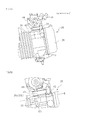
- FIGS. 5A and 5B are right side views of components such as the first intake pipe 42 and the engine 20.
- FIGS. 6A and 6B are left side views of components such as the first intake pipe 42 and the engine 20.
- the first intake pipe 42 has a flange portion 42c.
- the flange portion 42c is formed at a lower end of the first intake pipe 42.
- the flange portion 42c is fixed to a peripheral edge of the port connection opening 25a ( FIG. 3 ) of the cylinder head 26 by using an unillustrated bolt.
- a joint plane B between the first intake pipe 42 and the cylinder head 26 is located lower than a border line 26L of an upper wall 26a of the cylinder head 26.
- a lower end face 42b of the first intake pipe 42 is located lower than the border line 26L of the upper wall 26a of the cylinder head 26.
- the lower end face 42b of the first intake pipe 42 is inserted into the cylinder head 26. This allows the first intake pipe 42 and the throttle body 44 to be located at lower positions.
- the second intake pipe 46 extends upward from the throttle body 44.
- a material for the second intake pipe 46 is not particularly limited.
- the second intake pipe 46 may be a resin duct, a metal pipe or a rubber hose.
- the second intake pipe 46 extends obliquely upward and forward along the main frame 4.
- the air cleaner 30 is at least partially located below a front portion of the main frame 4 and rearward of the head pipe 3.
- the air cleaner 30 is at least partially located below the head pipe 3.
- a front end 34c of the air cleaner 30 is located more rearward than a front end 3a of the head pipe 3 and more forward than a rear end 3b of the head pipe 3.
- the air cleaner 30 is fixed to the main frame 4 by a bolt.
- the connection opening 32 is formed (see FIG. 8 ).
- the second intake pipe 46 is connected to the connection opening 32 of the air cleaner 30.
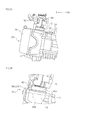
- FIG. 7 is a rear view of components such as the air cleaner 30 and the main frame 4.
- FIG. 8 is a diagram equivalent to FIG. 7 , from which the main frame 4 is removed.
- FIG. 9 is a left side view of the air cleaner 30 and its surroundings.
- FIG. 10 is a top cross-sectional view of the air cleaner 30.
- the air cleaner 30 has: an air cleaner case 34; and an element 36 located inside the air cleaner case 34.
- the air cleaner case 34 includes a front case member 34A and a rear case member 34B.
- the air cleaner case 34 further includes two ducts 38L and 38R.
- a groove 35 is formed at a position facing the main frame 4.
- the groove 35 is provided so as to surround part of lower and lateral surfaces of the main frame 4.
- the groove 35 extends obliquely downward and rearward along the main frame 4.
- the main frame 4 is at least partially located inside the groove 35.
- a lower portion of the main frame 4 is partially located inside the groove 35.
- the front case member 34A is located forward of the rear case member 34B. Upper ends 34Aa of the front case member 34A are located higher than upper ends 34Ba of the rear case member 34B. In side view, upper portions of the front case member 34A overlap with the main frame 4 (see FIG. 9 ).
- openings 33a and 33b are formed at the upper portions of the front case member 34A.
- the openings 33a and 33b are formed at symmetrical positions, with the main frame 4 sandwiched therebetween.
- the ducts 38L and 38R are attached to the openings 33a and 33b, respectively.
- the ducts 38L and 38R each extend obliquely downward and rearward from the front case member 34A.
- the reference sign "94" in FIG. 9 represents a harness in which wires of the motorcycle 1 are bound together. In side view, the harness 94 extends obliquely downward and rearward along the main frame 4.
- connection opening 32 of the air cleaner 30 is formed at a position located in a lower rear portion of the rear case member 34B and at a lateral surface of the groove 35.
- the connection opening 32 is opened obliquely rightward and downward.
- the connection opening 32 is located higher than a lower surface 34a of the air cleaner case 34, and located leftward of the main frame 4 (see FIG. 7 ) .
- the second intake pipe 46 is extended upward from the throttle body 44 so as to be inclined leftward toward the connection opening 32 and connected thereto. That is to say, the second intake pipe 46 extends leftward as it extends upward from the throttle body 44, and is then connected to the connection opening 32 of the air cleaner 30.
- connection opening 32 of the air cleaner 30 may be located rightward of the main frame 4.
- the second intake pipe 46 extends rightward as it extends upward from the throttle body 44, and is then connected to the connection opening 32.
- the connection opening 32 is offset leftward or rightward from a center of the main frame 4 in this manner, thereby allowing the second intake pipe 46 to be increased in length. Therefore, even when the first intake pipe 42 is short, an overall length of the intake passage 40 can be sufficiently ensured.
- the second intake pipe 46 extends obliquely upward and forward inside the air cleaner 30. As illustrated in FIGS. 8 and 10 , the second intake pipe 46 extends leftward from the connection opening 32, and is then bent to extend rightward. As illustrated in FIG. 10 , in this embodiment, the second intake pipe 46 has: a bent portion 46b; and an extended portion 46c extended rightward from an end of the bent portion 46b.
- the bent portion 46b is approximately U-shaped when viewed from above the motorcycle 1, and is located leftward of the main frame 4.
- the extended portion 46c extends straightly rightward from the end of the bent portion 46b. When viewed from behind the motorcycle 1, the extended portion 46c extends from a position leftward of the main frame 4 to a position rightward of the main frame 4. When viewed from above the motorcycle 1, the extended portion 46c is located so as to extend transversely under the main frame 4. At an end of the extended portion 46c, an intake opening 46d is formed. The intake opening 46d is located opposite to the bent portion 46b relative to the main frame 4. As illustrated in FIG. 8 , when viewed from behind the motorcycle 1, the intake opening 46d is located in an upper portion of the rear case member 34B and below the duct 38R. The intake opening 46d is opened rightward.
- the bent portion 46b and the extended portion 46c are located downstream of the element 36 inside the air cleaner 30. In other words, the bent portion 46b and the extended portion 46c are located at a "clean side" inside the air cleaner 30.
- Air introduced into the air cleaner 30 through the ducts 38L and 38R is guided to a region forward of the element 36 through the openings 33a and 33b. The air rearwardly passes through the element 36 and is thus cleaned by the element 36.
- the air, which has passed through the element 36 is introduced into the second intake pipe 46 from the intake opening 46d. The introduced air is guided to the intake port 25 of the engine 20 via the second intake pipe 46, the throttle body 44 and the first intake pipe 42.
- FIG. 11 is a rear perspective view of the second intake pipe 46 and its surroundings.
- FIG. 12 is an enlarged view of the main parts of FIG. 11 .
- FIG. 13 is a cross-sectional view taken along the line XIII-XIII of FIG. 12 . As illustrated in FIGS.
- a concave portion 46f facing the main frame 4 is formed at an outer wall of the second intake pipe 46.
- the concave portion 46f is formed at an outer wall of a region of the second intake pipe 46 located between the throttle body 44 and the connection opening 32.
- the concave portion 46f and the main frame 4 have a gap therebetween.
- the concave portion 46f is formed at the outer wall of the second intake pipe 46 in this manner, thereby making it possible to increase a bend radius of the second intake pipe 46 while avoiding interference between the second intake pipe 46 and the main frame 4. Hence, intake efficiency is further improved.
- the air cleaner 30 is at least partially provided above the throttle body 44. More specifically, a rear end 34b of the air cleaner 30 is located more rearward than a front extremity 44d of the throttle body 44 and more forward than a rear extremity 44e of the throttle body 44.
- the air cleaner 30 is located forward of the concave region 12.
- the lower surface 34a of the air cleaner 30 is located at the same height as that of the bottom surface 12a of the concave region 12.
- the throttle body 44 is at least partially located lower than the bottom surface 12a of the concave region 12.
- the injector 50 is located below the air cleaner 30 and the second intake pipe 46, and above the cylinder head 26. In this embodiment, the injector 50 is located below the rear portion of the air cleaner 30, and located more forward than the rear end 34b of the air cleaner 30. Furthermore, the injector 50 is located lower than the bottom surface 12a of the concave region 12.
- the concave region 12 is formed rearward of the head pipe 3, forward of the seat 9 and above the main frame 4 when the motorcycle 1 is viewed laterally. Therefore, a rider can easily straddle the main frame 4 when getting on the motorcycle 1, and thus can easily get on and off the motorcycle 1.
- the throttle body 44 is located so that the upper connection opening 44b, the lower connection opening 44a and the intake port 25 at least partially overlap with each other when viewed from above the motorcycle 1.
- the injector 50 is at least partially located more forward than the throttle body 44, and the injector 50 injects fuel toward the intake port 25. Therefore, the injector 50 can be further directed toward the combustion chamber 23. For example, fuel can be more directly supplied to the combustion chamber 23. Accordingly, the motorcycle 1 is capable of improving fuel efficiency while allowing a rider to get on and off the motorcycle 1 easily.
- the first intake pipe 42 has to be significantly bent forward in order to ensure an installation space for the injector 50.
- the injector 50 is at least partially located more forward than the throttle body 44. Therefore, the first intake pipe 42 does not have to be significantly bent forward. Accordingly, the degree of bending of the first intake pipe 42 can be reduced, and air is allowed to flow more smoothly through the first intake pipe 42. As a result, an improvement in intake efficiency is enabled.
- the throttle body 44 extends approximately vertically upward, thus making it possible to sufficiently ensure an installation space for the injector 50 in front of the throttle body 44.
- the injector 50 since the injector 50 is at least partially located more forward than the throttle body 44, wind flowing from the front due to running of the motorcycle 1 is likely to be directly blown against the injector 50. Therefore, the injector 50 can be efficiently cooled by wind. Accordingly, an increase in temperature of the injector 50 can be suppressed, and generation of bubbles in fuel can be inhibited. As a result, injection performance of the injector 50 can be favorably maintained.
- FIG. 14 is a perspective view of the motorcycle 1. It is to be noted that illustration of components inside the front cover 11 is omitted. As illustrated in FIG. 14 , the front cover 11 is opened forward. The fender 10 and the front cover 11 have a gap 19 therebetween. FIG. 15 is an enlarged view of a region XV of FIG. 14 .
- the front cover 11 is provided rightward and leftward of the air cleaner 30.
- the injector 50 is located below the air cleaner 30 and forward of the throttle body 44, and faces a rear surface of the fender 10. Through the gap 19 between the fender 10 and the front cover 11, spaces diagonally forward of the injector 50 are widely open.
- the reference sign "90" represents a fuel hose through which fuel is supplied to the injector 50. As illustrated in FIG. 1 , when the motorcycle 1 is viewed laterally, the fuel hose 90 extends obliquely upward and rearward along the seat frame 5. The fuel hose 90 is connected to a fuel pump (not illustrated) inside a fuel tank 92 located below the seat 9.
- the opening 27b opened and closed by the intake valve 27 is formed between the intake port 25 and the combustion chamber 23.
- the injector 50 is located so that the extension L2 of the axis of the injector 50 intersects the opening 27b. This allows the injection direction of the injector 50 to be further directed toward the combustion chamber 23, thereby realizing more favorable fuel injection. Hence, fuel efficiency is further improved.
- the concave region 12 is formed rearward of the head pipe 3, forward of the seat 9 and above the main frame 4 when the motorcycle 1 is viewed laterally.
- a region of the main frame 4, located between the seat 9 and the handlebar 7, is reduced in height.
- the air cleaner 30 is located below the main frame 4 and higher than the cylinder head 26. Therefore, a space formed below the air cleaner 30 and above the cylinder unit 22 is small.
- the throttle body 44 is inclined rearward so that when the motorcycle 1 is viewed laterally, the front end 44g of the lower edge of the throttle body 44 is located more forward than the front end 44c of the upper edge of the throttle body 44, and the rear end 44h of the lower edge is located more forward than the rear end 44f of the upper edge. That is to say, the throttle body 44 is inclined with respect to the vertical direction so as to be located more rearward as it extends upward. This can reduce the vertical length of the throttle body 44. Further, the injector 50 can be compactly located by utilizing the space forward of the throttle body 44. Therefore, it is unnecessary to raise the position of the concave region 12. Since the concave region 12 can be maintained at a low position, a rider is allowed to get on and off the motorcycle 1 with sufficient ease.
- the injector 50 is inclined forward so that the front end 50b of the lower edge of the injector 50 is located more rearward than the front end 50c of the upper edge of the injector 50, and the rear end 50d of the lower edge is located more rearward than the rear end 50a of the upper edge. That is to say, the injector 50 is inclined with respect to the vertical direction so as to be located more forward as it extends upward. This allows the injection direction of the injector 50 to be further directed toward the combustion chamber 23, thereby realizing more favorable fuel injection. Hence, fuel efficiency is further improved. In addition, the vertical length of the injector 50 can be reduced. Therefore, the concave region 12 can be maintained at a low position, thus allowing a rider to get on and off the motorcycle 1 with sufficient ease.
- the single throttle valve 43 is incorporated into the throttle body 44 and thus the length A1 of the throttle body 44 is shortened.
- the length A1 of the throttle body 44 is equal to or less than 1.5 times the length A2 of the injector 50. Therefore, the throttle body 44 can be easily located in a small space between the main frame 4 and the cylinder head 26.
- the length A3 of the first intake pipe 42 is shorter than the length A1 of the throttle body 44.
- the length A3 of the first intake pipe 42 is shortened in this manner, thereby allowing the injector 50 to be located close to the combustion chamber 23. Therefore, the injector 50 can be further directed toward the combustion chamber 23, thereby further improving fuel efficiency.
- the lower end face 42b of the first intake pipe 42 is located below the border line 26L of the upper wall 26a of the cylinder head 26. This allows the first intake pipe 42 and the throttle body 44 to be located at lower positions. Therefore, an installation space for the throttle body 44 and the injector 50 can be sufficiently ensured below the main frame 4. As a result, the throttle body 44 and the injector 50 can be compactly located while a rider is allowed to easily get on and off the motorcycle 1.
- the connection opening 32 located leftward of the main frame 4, is formed in the air cleaner 30.
- the second intake pipe 46 is extended upward from the throttle body 44 so as to be inclined leftward toward the connection opening 32 and connected thereto. This can increase the length of the second intake pipe 46 compared with a case where the second intake pipe 46 extends straightly forward as it extends upward. Therefore, even when the first intake pipe 42 is short, the overall length of the intake passage 40 can be sufficiently ensured. Accordingly, intake characteristics of the engine 20 can be favorably maintained.
- the second intake pipe 46 extends obliquely upward from the throttle body 44, the second intake pipe 46 can be reduced in lateral dimension compared with a case where the second intake pipe 46 extends laterally from the throttle body 44.
- the connection opening 32 is formed leftward of the main frame 4 in the present embodiment, the connection opening 32 may be formed rightward of the main frame 4. In that case, the second intake pipe 46 is extended upward from the throttle body 44 so as to be inclined rightward toward the connection opening 32 and connected thereto. Also in such a case, the above-described effects are obtainable.
- connection opening 32 of the air cleaner 30 is formed at the rear portion of the air cleaner 30.
- the connection opening 32 is located higher than the lower surface 34a of the air cleaner 30.
- the second intake pipe 46 When viewed from behind the motorcycle 1, the second intake pipe 46 extends leftward as it extends upward from the throttle body 44, and is then bent rightward inside the air cleaner 30 (see FIG. 10 ). Inside the air cleaner 30, the second intake pipe 46 is bent by 90° or more. This can further increase the length of the second intake pipe 46 without increasing the space occupied by the region of the second intake pipe 46 located outside the air cleaner 30, and thus can sufficiently ensure the overall length of the intake passage 40.
- the bending angle of the second intake pipe 46 inside the air cleaner 30 is not particularly limited.
- the bending angle may be 120° or more, or may be 135° or more.
- the entire second intake pipe 46 (including the regions thereof located inside and outside the air cleaner 30) is bent by 180°.
- the bending angle of the entire second intake pipe 46 is also not particularly limited.
- the second intake pipe 46 extends from a position leftward of the main frame 4 to a position rightward of main frame 4. Specifically, when viewed from above, the second intake pipe 46 is located so as to extend transversely under the main frame 4. This can further increase the length of the second intake pipe 46 without increasing the space occupied by the region of the second intake pipe 46 located outside the air cleaner 30, and thus can sufficiently ensure the overall length of the intake passage 40. Note that when the connection opening 32 is formed rightward of the main frame 4, the second intake pipe 46 may be located so as to extend from a position rightward of the main frame 4 to a position leftward of the main frame 4 inside the air cleaner 30. Also in such a case, the above-described effects are obtainable.
- the second intake pipe 46 is located so as to be overlapped with the main frame 4 when the motorcycle 1 is viewed laterally. As the second intake pipe 46 and the main frame 4 are overlapped with each other along the vertical direction, the installation space for the injector 50 can be ensured below the second intake pipe 46 accordingly. Furthermore, the length of the second intake pipe 46 can be increased, and thus the overall length of the intake passage 40 can be sufficiently ensured.
- the concave portion 46f facing the main frame 4 is formed at the outer wall of the second intake pipe 46. This can increase the degree of bending of the second intake pipe 46 while avoiding interference between the second intake pipe 46 and the main frame 4. Hence, intake efficiency can be further improved.
- the rear end 34b of the air cleaner 30 is located more rearward than the front extremity 44d of the throttle body 44, and more forward than the rear extremity 44e of the throttle body 44. This can shorten an overall fore-and-aft length of the air cleaner 30 and the throttle body 44. Hence, the air cleaner 30 and the intake passage 40 can be compactly located while a volume of the air cleaner 30 is ensured.
- the injector 50 is located below the air cleaner 30. This allows a space, located below the air cleaner 30 and forward of the throttle body 44, to be effectively utilized as the installation space for the injector 50. Thus, the injector 50 can be compactly located. Besides, wind flowing from the front due to running of the motorcycle 1 blows against the lower surface 34a of the air cleaner case 34 or flows along the lower surface 34a, and thus the wind is guided toward the injector 50.
- the lower surface 34a of the air cleaner case 34 functions as a baffle plate, thereby making it possible to further facilitate cooling of the injector 50.
- FIG. 16 is a schematic left side cross-sectional view of the throttle body 44 of a motorcycle according to Embodiment 2, and its surroundings.
- the injector 50 attached to the throttle body 44 in Embodiment 1 is attached to the first intake pipe 42.
- the injector 50 is attached to the first intake pipe 42 so as to be at least partially located more forward than the throttle body 44.
- Other features are similar to those of Embodiment 1, and therefore, description thereof will be omitted.
- the injector 50 is attached to the first intake pipe 42 so as to be at least partially located more forward than the throttle body 44. Therefore, the injector 50 can be located closer to the combustion chamber 23. Accordingly, the injector 50 can be further directed toward the combustion chamber 23, thereby further improving fuel efficiency.
Landscapes
- Engineering & Computer Science (AREA)
- Chemical & Material Sciences (AREA)
- Combustion & Propulsion (AREA)
- Mechanical Engineering (AREA)
- General Engineering & Computer Science (AREA)
- Automatic Cycles, And Cycles In General (AREA)
- Control Of Throttle Valves Provided In The Intake System Or In The Exhaust System (AREA)
- Cooling, Air Intake And Gas Exhaust, And Fuel Tank Arrangements In Propulsion Units (AREA)
Abstract
Description
- The present invention relates to motorcycles.
- "Underbone type" motorcycles have conventionally been known. An underbone type motorcycle includes a body frame having: a head pipe for rotatably supporting a handlebar; and a main frame extending obliquely downward and rearward from the head pipe. An engine is located below the body frame. In the underbone type motorcycle, a region of the main frame, located between the handlebar and a seat, is reduced in height. Therefore, a rider can easily straddle the main frame when getting on the motorcycle, and thus can easily get on and off the motorcycle.
-
JP-A-2000-249028 - In the motorcycle disclosed in
JP-A-2000-249028 - The present invention has been made in view of the above conventional problems, and its main object is to provide a motorcycle capable of enhancing engine output or improving fuel efficiency while allowing a rider to get on and off the motorcycle easily.
- The main object of the present invention is achieved by a motorcycle according to
claim 1. - A motorcycle according to the present invention includes: a body frame having a head pipe, and a main frame extending obliquely downward and rearward from the head pipe; a seat supported by the body frame and located rearward of the head pipe; an engine having a cylinder unit located below the main frame, the engine being supported by the main frame so as not to be swingable; an air cleaner at least partially located below the main frame and higher than the cylinder unit; and an intake passage connected to the cylinder unit and the air cleaner. When the motorcycle is viewed laterally, a concave region is formed rearward of the head pipe, forward of the seat and above the main frame. Inside the cylinder unit, there are formed a combustion chamber and an intake port at least partially located more forward than the combustion chamber. The intake passage has: a first intake pipe connected to the intake port; a throttle body connected to the first intake pipe and incorporating a throttle valve; and a second intake pipe connected to the throttle body and the air cleaner. The throttle body is provided at its lower end portion with a lower connection opening connected to the first intake pipe, and is provided at its upper end portion with an upper connection opening connected to the second intake pipe. The upper connection opening, the lower connection opening, and the intake port are located so as to be at least partially overlapped with each other when viewed from above the motorcycle. The motorcycle further includes an injector for injecting fuel toward the intake port, the injector being attached to the throttle body or the first intake pipe so as to be at least partially located more forward than the throttle body.
- In the motorcycle, the concave region is formed rearward of the head pipe, forward of the seat and above the main frame when the motorcycle is viewed laterally. Therefore, a rider can easily straddle the main frame when getting on the motorcycle, and thus can easily get on and off the motorcycle. Moreover, the upper connection opening of the throttle body, the lower connection opening thereof, and the intake port are located so as to be at least partially overlapped with each other when viewed from above the motorcycle. Furthermore, the injector is at least partially located more forward than the throttle body, and the injector injects fuel toward the intake port. Therefore, an injection direction of the injector can be further directed toward the combustion chamber. Accordingly, the motorcycle is capable of improving fuel efficiency while allowing a rider to get on and off the motorcycle easily.
- For example, if the entire injector is located more rearward than the throttle body, the first intake pipe has to be significantly bent forward in order to ensure an installation space for the injector. However, in the motorcycle, the injector is at least partially located more forward than the throttle body. Therefore, the first intake pipe does not have to be significantly bent forward. Accordingly, the degree of bending of the first intake pipe can be reduced, thus allowing air to flow more smoothly through the first intake pipe. As a result, an improvement in intake efficiency is enabled.
- In one preferred aspect, the throttle body preferably includes an upper edge and a lower edge. The throttle body is preferably inclined rearward so that a front end of the lower edge is located more forward than a front end of the upper edge, and a rear end of the lower edge is located more forward than a rear end of the upper edge.
- Such a structure can reduce a vertical length of the throttle body. Since utilization of a space located forward of the throttle body is facilitated, the injector can be compactly located in this space. Therefore, the concave region can be maintained at a low position, thus allowing a rider to get on and off the motorcycle with sufficient ease.
- In another preferred aspect, the injector preferably includes an upper edge and a lower edge. The injector is preferably inclined forward so that a front end of the lower edge is located more rearward than a front end of the upper edge, and a rear end of the lower edge is located more rearward than a rear end of the upper edge.
- Such a structure allows the injection direction of the injector to be further directed toward the combustion chamber. Hence, fuel efficiency is further improved. Since the injector can be reduced in vertical length, the concave region can be maintained at a low position, thus allowing a rider to get on and off the motorcycle with sufficient ease.
- In still another preferred aspect, between the intake port and the combustion chamber, there is preferably formed an opening opened and closed by an intake valve, and the injector is preferably located so that an extension of an axis of the injector intersects the opening.
- Such a structure allows the injection direction of the injector to be further directed toward the combustion chamber. Hence, fuel efficiency is further improved.
- In yet another preferred aspect, when the motorcycle is viewed laterally, a lower end face of the first intake pipe is preferably located below a border line of an upper wall of the cylinder unit.
- Such a structure allows the first intake pipe and the throttle body to be located at lower positions. Therefore, an installation space for the injector can be sufficiently ensured below the main frame. As a result, the throttle body and the injector can be compactly located, while a rider is allowed to easily get on and off the motorcycle.
- In still yet another preferred aspect, the throttle body preferably has a length equal to or less than 1.5 times that of the injector.
- Such a structure allows the throttle body to be easily located in a small space between the main frame and the cylinder unit.
- In another preferred aspect, the first intake pipe preferably has a length shorter than that of the throttle body.
- In such a structure, the length of the first intake pipe is short, thus allowing the injector to be located close to the combustion chamber. Therefore, the injector can be more favorably directed toward the combustion chamber, resulting in a further improvement in fuel efficiency.
- In still another preferred aspect, in the air cleaner, there is preferably formed a connection opening located rightward or leftward of the main frame. When viewed from behind the motorcycle, the second intake pipe is preferably extended upward from the throttle body so as to be inclined rightward or leftward toward the connection opening and connected thereto.
- Such a structure can increase a length of the second intake pipe compared with a case where the second intake pipe extends straightly forward as it extends upward. Therefore, even when the first intake pipe is short, an overall length of the intake passage can be sufficiently ensured. Accordingly, intake characteristics of the engine can be favorably maintained.
- In yet another preferred aspect, the connection opening is preferably formed at a rear portion of the air cleaner.
- Such a structure can reduce a region of the second intake pipe located outside of the air cleaner. Therefore, a space located between the main frame and the cylinder unit and occupied by the second intake pipe can be reduced, and the installation space for the injector can be sufficiently ensured.
- In still yet another preferred aspect, the second intake pipe is preferably bent by 90° or more inside the air cleaner.
- Such a structure can further increase the length of the second intake pipe without increasing the space occupied by the region of the second intake pipe located outside the air cleaner. Thus, the overall length of the intake passage can be sufficiently ensured.
- In another preferred aspect, inside the air cleaner, the second intake pipe preferably extends from a position leftward of the main frame to a position rightward of the main frame, or extends from a position rightward of the main frame to a position leftward of the main frame.
- Such a structure can further increase the length of the second intake pipe without increasing the space occupied by the region of the second intake pipe located outside the air cleaner. Thus, the overall length of the intake passage can be sufficiently ensured.
- In still another preferred aspect, the second intake pipe is preferably located so as to be overlapped with the main frame when the motorcycle is viewed laterally.
- Such a structure can increase the length of the second intake pipe, and thus the overall length of the intake passage can be sufficiently ensured.
- In yet another preferred aspect, at an outer wall of the second intake pipe, there is preferably formed a concave portion facing the main frame.
- Such a structure can increase the degree of bending of the second intake pipe while avoiding interference between the second intake pipe and the main frame. Hence, intake efficiency is further improved.
- In still yet another preferred aspect, a rear end of the air cleaner is preferably located more rearward than a front extremity of the throttle body, and more forward than a rear extremity of the throttle body.
- Such a structure can shorten an overall fore-and-aft length of the air cleaner and the throttle body. Hence, the air cleaner and the intake passage can be compactly located while a volume of the air cleaner is ensured.
- In another preferred aspect, the injector is preferably located below the air cleaner.
- Such a structure allows a space, located below the air cleaner and forward of the throttle body, to be effectively utilized as the installation space for the injector. Thus, the injector can be compactly located.
-
-
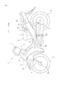
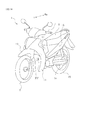
FIG. 1 is a side view of a motorcycle according toEmbodiment 1 of the present invention. -
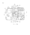
FIG. 2 is a side view illustrating components of the motorcycle according toEmbodiment 1 of the present invention, such as part of an engine and an air cleaner. -
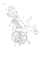
FIG. 3 is a left side cross-sectional view of a throttle body according toEmbodiment 1 of the present invention, and its surroundings. -
FIG. 4 is a top plan view of the throttle body according toEmbodiment 1 of the present invention, and its surroundings. -
FIG. 5A is a right side view of part of the engine according toEmbodiment 1 of the present invention, and its surroundings. -
FIG. 5B is an enlarged view of the main parts ofFIG. 5A . -
FIG. 6A is a left side view of part of the engine according toEmbodiment 1 of the present invention, and its surroundings. -
FIG. 6B is an enlarged view of the main parts ofFIG. 6A . -
FIG. 7 is a rear view of the air cleaner according toEmbodiment 1 of the present invention, and its surroundings. -
FIG. 8 is a rear view of the air cleaner according toEmbodiment 1 of the present invention and its surroundings, from which a main frame is removed. -
FIG. 9 is a left side view of the air cleaner according toEmbodiment 1 of the present invention, and its surroundings. -
FIG. 10 is a top cross-sectional view of the air cleaner according toEmbodiment 1 of the present invention, and its surroundings. -
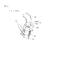
FIG. 11 is a rear perspective view of a second intake pipe according toEmbodiment 1 of the present invention, and its surroundings. -
FIG. 12 is an enlarged view of the main parts ofFIG. 11 . -
FIG. 13 is a cross-sectional view taken along the line XIII-XIII ofFIG. 12 . -
FIG. 14 is a perspective view of the motorcycle according toEmbodiment 1 of the present invention. -
FIG. 15 is an enlarged view of a region XV ofFIG. 14 . -
FIG. 16 is a left side cross-sectional view of an intake passage according toEmbodiment 2 of the present invention, and its surroundings. - Hereinafter, one embodiment of the present invention will be described. In the following description, "front", "rear", "right", "left", "up" and "down" mean front, rear, right, left, up and down with respect to an occupant of a
motorcycle 1, respectively. Reference signs "F" , "Re", "R" and "L" used in the drawings represent front, rear, right and left, respectively. - As illustrated in
FIG. 1 , the motorcycle according to the present embodiment is the "underbone type"motorcycle 1. Themotorcycle 1 includes abody frame 2 made up of a plurality of frame members. Thebody frame 2 includes ahead pipe 3, amain frame 4 and aseat frame 5. In theunderbone type motorcycle 1, aconcave region 12 is formed rearward of thehead pipe 3, forward of aseat 9 and above themain frame 4 when themotorcycle 1 is viewed laterally. A region of themain frame 4, located between theseat 9 and thehead pipe 3, is reduced in height. This allows a rider to straddle themain frame 4 easily. In other words, a rider is allowed to straddle a body of themotorcycle 1 easily. - A
handlebar 7 is rotatably attached above thehead pipe 3. Afront fork 6 is supported below thehead pipe 3. Anaxle 8a is fixed to lower end portions of thefront fork 6. Afront wheel 8 is rotatably attached to theaxle 8a. Afender 10 is provided above and rearward of thefront wheel 8. - As illustrated in
FIG. 2 , themain frame 4 extends obliquely downward and rearward from thehead pipe 3 in side view. Anengine 20 is located below themain frame 4. Anair cleaner 30 is located above theengine 20. Theair cleaner 30 is connected to acylinder unit 22 of theengine 20 via anintake passage 40. One end portion of theintake passage 40 is connected to thecylinder unit 22. In side view, theintake passage 40 extends upward from thecylinder unit 22. The other end portion of theintake passage 40 is connected to theair cleaner 30. Theair cleaner 30 cleans air to be supplied to theengine 20. Air is cleaned by being passed through theair cleaner 30, and is then supplied to theengine 20 through theintake passage 40. A front cover 11 (FIG. 1 ) is located forward of thehead pipe 3, leftward of theair cleaner 30, rightward of theair cleaner 30, partially leftward of theengine 20 and partially rightward of theengine 20. - As illustrated in
FIG. 1 , theseat frame 5 extends obliquely upward and rearward from a position somewhere along themain frame 4 in side view. Theseat 9 is located above theseat frame 5. Theseat 9 is supported by theseat frame 5. Arear cushion unit 13 is located below theseat frame 5. Therear cushion unit 13 is supported at its upper end portion by theseat frame 5, and is supported at its lower end portion by arear frame 14. Therear frame 14 is provided at its front portion with apivot shaft 14a. Therear frame 14 is swingable up and down around thepivot shaft 14a. At a rear portion of therear frame 14, arear wheel 15 is supported. Abody cover 16 is located laterally of themain frame 4 andseat frame 5 of thebody frame 2. - As illustrated in
FIG. 2 , themain frame 4 is provided with abracket 17. Thebracket 17 extends downward from themain frame 4. Theengine 20 includes acrankcase 18. At an upper front portion of thecrankcase 18, a boss portion (not illustrated) is formed. The boss portion of thecrankcase 18 is fixed to thebracket 17 by abolt 18a so as not to be swingable. Although not illustrated, a rear portion of thecrankcase 18 is also fixed to another bracket by a bolt so as not to be swingable. Thus, theengine 20 is supported by thebody frame 2 so as not to be swingable. Thecrankcase 18 incorporates unillustrated components such as a crankshaft and a transmission mechanism. - The
engine 20 further includes: acylinder block 24 extending forward from thecrankcase 18; acylinder head 26 fixed to a front end portion of thecylinder block 24; and ahead cover 28 fixed to a front end portion of thecylinder head 26. Thecylinder block 24, thecylinder head 26 and thehead cover 28 constitute thecylinder unit 22. It is to be noted that any two or three of thecylinder block 24, thecylinder head 26 and thehead cover 28 may be formed integrally with each other. The number of members constituting thecylinder unit 22 is not limited in any way. Thecylinder unit 22 is located forward of thecrankcase 18. Theentire cylinder unit 22 may be formed separately from thecrankcase 18. Alternatively, part of thecylinder unit 22 may be formed integrally with thecrankcase 18. Thecylinder unit 22 is located lower than abottom surface 12a of theconcave region 12. A center line of thecylinder block 24, i.e., a cylinder axis L1, extends obliquely forward and upward. In this embodiment, the cylinder axis L1 has an inclination angle of about 10° relative to a horizontal line, and thus extends substantially horizontally. The inclination angle of the cylinder axis L1 may be 10° or less, 15° or less, or 30° or less, for example. -
FIG. 3 is a left side cross-sectional view of part of thecylinder unit 22 and part of theintake passage 40. As illustrated inFIG. 3 , in thecylinder head 26, acombustion chamber 23 and anintake port 25, at least partially located more forward than thecombustion chamber 23, are formed. Theintake port 25 is formed in an upper half portion of thecylinder head 26. Theintake port 25 is bent. In this embodiment, theintake port 25 extends obliquely forward and upward from thecombustion chamber 23, and then extends upward. Between theintake port 25 and thecombustion chamber 23, there is formed anopening 27b. Theopening 27b is opened and closed by anintake valve 27. Theintake valve 27 has an umbrella-like valve body 27a and a rod-like stem 27d. Theintake valve 27 is driven by acamshaft 27c via an unillustrated rocker arm. With a rotation of thecamshaft 27c, theintake valve 27 moves back and forth relative to theopening 27b along an axial direction of thestem 27d. Anaxis 27e of thestem 27d has an inclination angle θ1 ranging from 30° to 40°, for example, with respect to a horizontal line. - Although not illustrated, in a lower half portion of the
cylinder head 26, an exhaust port located more forward than thecombustion chamber 23 is formed. Between the exhaust port and thecombustion chamber 23, there is formed another opening. This opening is opened and closed by an unillustrated exhaust valve. The exhaust port is connected with an unillustrated exhaust pipe. - The
opening 27b is formed at a lower end of theintake port 25. At an upper end of theintake port 25, aport connection opening 25a is formed. Theport connection opening 25a is connected with athrottle body 44 via afirst intake pipe 42. Thethrottle body 44 is provided at its upper end portion with anupper connection opening 44b. Theupper connection opening 44b is connected with one end portion of asecond intake pipe 46. The other end portion of thesecond intake pipe 46 is inserted into theair cleaner 30 through aconnection opening 32 of the air cleaner 30 (seeFIGS. 2 and8 ). Thefirst intake pipe 42, thethrottle body 44 and thesecond intake pipe 46 constitute theintake passage 40. As illustrated inFIG. 2 , a lower portion of theintake passage 40 is located between theengine 20 and themain frame 4. - As illustrated in
FIG. 3 , thethrottle body 44 has a cylindrical shape. At a longitudinal center of thethrottle body 44, asingle throttle valve 43 is located. Thethrottle valve 43 includes: avalve shaft 43b; and avalve plate 43a fixed to thevalve shaft 43b. Thethrottle body 44 is provided at its lower end portion with alower connection opening 44a connected to thefirst intake pipe 42, and is provided at its upper end portion with theupper connection opening 44b connected to thesecond intake pipe 46. Thethrottle body 44 is located above theintake port 25 and placed in a standing position. In other words, as illustrated inFIGS. 3 and4 , thethrottle body 44 is located so that when viewed from above themotorcycle 1, theupper connection opening 44b, thelower connection opening 44a and theintake port 25 are at least partially overlapped with each other. Thus, a space is ensured in front of thethrottle body 44. Utilizing this space, aninjector 50 is located so as to be at least partially located more forward than thethrottle body 44. Thethrottle body 44 is provided at its front portion with aninjector placement portion 47. Although not illustrated inFIG. 4 , theinjector 50 is inserted into ahole 47a formed in theinjector placement portion 47. - As illustrated in
FIG. 4 , when viewed from above themotorcycle 1, a front end of theport connection opening 25a is located more forward than a front end of thelower connection opening 44a. A rear end of thelower connection opening 44a is located more rearward than a front end of theupper connection opening 44b. The front end of theupper connection opening 44b is located more forward than a rear end of theport connection opening 25a. The rear end of thelower connection opening 44a is located at substantially the same position as the rear end of theport connection opening 25a, or located more rearward than the rear end of theport connection opening 25a. The rear end of theport connection opening 25a is located more forward than a center 44bA of theupper connection opening 44b. The rear end of thelower connection opening 44a is located more forward than the center 44bA of theupper connection opening 44b. The front end of theupper connection opening 44b is located at the same position as a center 25aA of theport connection opening 25a, or located more rearward than the center 25aA. Theport connection opening 25a has a diameter smaller than that of theupper connection opening 44b. The diameter of theport connection opening 25a is larger than that of thelower connection opening 44a. When viewed from above themotorcycle 1, the center 44bA of theupper connection opening 44b, a center of thelower connection opening 44a, and the center 25aA of theport connection opening 25a are located on a straight line L3. On the straight line L3, a center of thehole 47a of theinjector placement portion 47 is also located. - In this embodiment, as illustrated in
FIG. 3 , thethrottle body 44 is inclined rearward so that in side view, afront end 44g of a lower edge of thethrottle body 44 is located more forward than afront end 44c of an upper edge of thethrottle body 44, and arear end 44h of the lower edge is located more forward than arear end 44f of the upper edge. That is to say, thethrottle body 44 is inclined with respect to a vertical direction so as to be located more rearward as it extends upward. Thefront end 44g of the lower edge of thethrottle body 44 is located higher than therear end 44h of the lower edge, and thefront end 44c of the upper edge is located higher than therear end 44f of the upper edge. For example, anaxis 44L of thethrottle body 44 may be inclined rearward at an angle θ2 ranging from 5° to 30° with respect to a vertical axis. The angle θ2 may be in the range of 5° to 15°. Thus, in contrast to a case where theaxis 44L of thethrottle body 44 coincides with the vertical axis, an increase in height of the throttle body 44 (or in vertical length of the throttle body 44) can be prevented while a length A1 of thethrottle body 44 is ensured. For example, thethrottle body 44 may have the length A1 equal to or less than 1.5 times (e.g. , about 1.3 times) a length A2 of theinjector 50. Thefront end 44c of the upper edge of the throttle body 44 (i.e., an upper end of the throttle body 44) is located lower than anupper end 50a of theinjector 50. - As illustrated in
FIG. 3 , theinjector 50 is attached to thethrottle body 44 so as to be at least partially located more forward than thethrottle body 44. In the present embodiment, theentire injector 50 is located more forward than thethrottle valve 43. Theinjector 50 injects fuel toward theintake port 25. In this embodiment, thethrottle body 44 is provided at its front portion with theinjector placement portion 47. In theinjector placement portion 47, thehole 47a extending obliquely downward is formed. Theinjector 50 is fixed by being inserted into thehole 47a. Atip end portion 52 of an injection nozzle of theinjector 50 is located in the vicinity of an inner surface of thethrottle body 44. When themotorcycle 1 is viewed laterally, theinjector 50 is located so that an extension L2 of an axis of theinjector 50 intersects theopening 27b. In other words, the extension L2 of the axis of theinjector 50 extends toward a back surface of thevalve body 27a of theintake valve 27 in a fully closed position. Theinjector 50 is located at a position from which fuel can be directly supplied to thecombustion chamber 23 when theintake valve 27 is opened. The extension L2 of the axis of theinjector 50 preferably forms an angle ranging from 30° to 40° with respect to theaxis 27e of thestem 27d of theintake valve 27. Thus, an injection direction of theinjector 50 can be further directed toward thecombustion chamber 23. - In this embodiment, the extension L2 of the axis of the
injector 50 does not overlap with thestem 27d of the fully closedintake valve 27. In this embodiment, the extension L2 of the axis of theinjector 50 extends toward an upper portion of thevalve body 27a of the fully closedintake valve 27. In other words, the extension L2 of the axis of theinjector 50 passes through an upper half region of theopening 27b when theintake valve 27 is opened. However, the direction of the extension L2 is not limited to the above direction. For example, the extension L2 of the axis of theinjector 50 may intersect an inner surface of theintake port 25. Also in such a case, fuel injected from theinjector 50 is guided downward by air flowing through theintake port 25, thus allowing fuel to be effectively supplied to thecombustion chamber 23. Theinjector 50 has an injection width W expanded gradually from thetip end portion 52 of the nozzle toward theopening 27b. When viewed in the fuel injection direction, the injection width W of theinjector 50 is smaller than an inner diameter of theport connection opening 25a, and is approximately equal to or smaller than an inner diameter of theopening 27b. Thus, fuel can be supplied more directly to thecombustion chamber 23. - The
injector 50 is substantially vertically extended, but is inclined forward so that afront end 50b of a lower edge of theinjector 50 is located more rearward than afront end 50c of an upper edge of theinjector 50, and arear end 50d of the lower edge is located more rearward than arear end 50a of the upper edge. That is to say, theinjector 50 is inclined with respect to a vertical direction so as to be located more forward as it extends upward. Thus, thefront end 50b of the lower edge of theinjector 50 is located lower than therear end 50d of the lower edge, and thefront end 50c of the upper edge is located lower than therear end 50a of the upper edge. For example, the axis of theinjector 50 may have an inclination angle in the range of 10° to 30° or in the range of 15° to 25° with respect to a vertical axis. Theinjector 50 is located in the forwardly-inclined position in this manner, thereby allowing the injection direction of theinjector 50 to be further directed toward thecombustion chamber 23. Furthermore, theinjector 50 can be reduced in vertical length. - The
first intake pipe 42 serves as a member interposed between thethrottle body 44 and thecylinder head 26. In the present embodiment, thefirst intake pipe 42 is formed separately from thethrottle body 44 and then fitted to thethrottle body 44. However, thefirst intake pipe 42 may be formed integrally with thethrottle body 44. Although not illustrated, in the present embodiment, thefirst intake pipe 42 includes: a core made of a resin; and heat-resistant rubber located around the core. Thefirst intake pipe 42 is formed into a cylindrical shape and is connected to the port connection opening 25a of theintake port 25. Thelower connection opening 44a of thethrottle body 44 is inserted into an upper connection opening 42a of thefirst intake pipe 42. Thefirst intake pipe 42 and thethrottle body 44 are fixed to each other by a fixation band (not illustrated). Thefirst intake pipe 42 is interposed between thethrottle body 44 and theintake port 25 in this manner, thus making it possible to suppress influence of heat of theengine 20 exerted on theinjector 50. That is to say, heating of theinjector 50 by theengine 20 is suppressed. As a result, an excessive increase in temperature of theinjector 50 is prevented. Furthermore, thefirst intake pipe 42 includes the rubber (heat-resistant rubber) and thus can absorb vibration of theengine 20. Therefore, theinjector 50 is unlikely to be influenced by vibration of theengine 20. In this embodiment, thefirst intake pipe 42 extends straightly from thethrottle body 44 to theintake port 25. A region of thefirst intake pipe 42, located in the vicinity of theport connection opening 25a, is substantially straightly formed. A region of theintake passage 40, located in the vicinity of theengine 20, is straightly formed in this manner, thus making it possible to reduce flow resistance of air sucked into theengine 20, compared with a case where the region of theintake passage 40 located in the vicinity of theengine 20 is bent. As a result, intake efficiency of theengine 20 is improved. - The
first intake pipe 42 has a length A3 shorter than the length A1 of thethrottle body 44. For example, the length A3 of thefirst intake pipe 42 is 0.1 to 0.4 times (e.g., 0.2 to 0.3 times) the length A1 of thethrottle body 44. Thefirst intake pipe 42 is sufficiently short, thus allowing theinjector 50 to be located close to thecombustion chamber 23. Therefore, fuel can be more directly supplied to thecombustion chamber 23 from theinjector 50. Note that when theinjector 50 is located close to thecombustion chamber 23, theinjector 50 may be increased in temperature, and bubbles might be generated in fuel. However, in the present embodiment, theinjector 50 is located more forward than thethrottle body 44; hence, when themotorcycle 1 runs, wind blows from the front, and thus theinjector 50 can be cooled by the wind. Consequently, generation of bubbles in fuel can be prevented. -
FIGS. 5A and 5B are right side views of components such as thefirst intake pipe 42 and theengine 20.FIGS. 6A and 6B are left side views of components such as thefirst intake pipe 42 and theengine 20. As illustrated inFIGS. 5B and6B , thefirst intake pipe 42 has aflange portion 42c. Theflange portion 42c is formed at a lower end of thefirst intake pipe 42. Theflange portion 42c is fixed to a peripheral edge of theport connection opening 25a (FIG. 3 ) of thecylinder head 26 by using an unillustrated bolt. In side view, a joint plane B between thefirst intake pipe 42 and thecylinder head 26 is located lower than aborder line 26L of anupper wall 26a of thecylinder head 26. In other words, when themotorcycle 1 is viewed laterally, alower end face 42b of thefirst intake pipe 42 is located lower than theborder line 26L of theupper wall 26a of thecylinder head 26. Thelower end face 42b of thefirst intake pipe 42 is inserted into thecylinder head 26. This allows thefirst intake pipe 42 and thethrottle body 44 to be located at lower positions. - As illustrated in
FIG. 2 , thesecond intake pipe 46 extends upward from thethrottle body 44. A material for thesecond intake pipe 46 is not particularly limited. For example, thesecond intake pipe 46 may be a resin duct, a metal pipe or a rubber hose. When themotorcycle 1 is viewed laterally, thesecond intake pipe 46 extends obliquely upward and forward along themain frame 4. Theair cleaner 30 is at least partially located below a front portion of themain frame 4 and rearward of thehead pipe 3. Furthermore, theair cleaner 30 is at least partially located below thehead pipe 3. In this embodiment, afront end 34c of theair cleaner 30 is located more rearward than afront end 3a of thehead pipe 3 and more forward than arear end 3b of thehead pipe 3. Theair cleaner 30 is fixed to themain frame 4 by a bolt. At a rear portion of theair cleaner 30, theconnection opening 32 is formed (seeFIG. 8 ). Thesecond intake pipe 46 is connected to the connection opening 32 of theair cleaner 30. -
FIG. 7 is a rear view of components such as theair cleaner 30 and themain frame 4.FIG. 8 is a diagram equivalent toFIG. 7 , from which themain frame 4 is removed.FIG. 9 is a left side view of theair cleaner 30 and its surroundings. AndFIG. 10 is a top cross-sectional view of theair cleaner 30. As illustrated inFIG. 10 , theair cleaner 30 has: an aircleaner case 34; and anelement 36 located inside theair cleaner case 34. As illustrated inFIG. 9 , theair cleaner case 34 includes afront case member 34A and arear case member 34B. As illustrated inFIG. 8 , theair cleaner case 34 further includes twoducts - As illustrated in
FIGS. 8 and9 , at an upper surface of theair cleaner case 34, agroove 35 is formed at a position facing themain frame 4. Thegroove 35 is provided so as to surround part of lower and lateral surfaces of themain frame 4. Thegroove 35 extends obliquely downward and rearward along themain frame 4. Themain frame 4 is at least partially located inside thegroove 35. In the present embodiment, a lower portion of themain frame 4 is partially located inside thegroove 35. Thefront case member 34A is located forward of therear case member 34B. Upper ends 34Aa of thefront case member 34A are located higher than upper ends 34Ba of therear case member 34B. In side view, upper portions of thefront case member 34A overlap with the main frame 4 (seeFIG. 9 ). At the upper portions of thefront case member 34A,openings openings main frame 4 sandwiched therebetween. Theducts openings ducts front case member 34A. The reference sign "94" inFIG. 9 represents a harness in which wires of themotorcycle 1 are bound together. In side view, theharness 94 extends obliquely downward and rearward along themain frame 4. - As illustrated in
FIG. 8 , the connection opening 32 of theair cleaner 30 is formed at a position located in a lower rear portion of therear case member 34B and at a lateral surface of thegroove 35. Theconnection opening 32 is opened obliquely rightward and downward. Furthermore, theconnection opening 32 is located higher than alower surface 34a of theair cleaner case 34, and located leftward of the main frame 4 (seeFIG. 7 ) . When viewed from behind themotorcycle 1, thesecond intake pipe 46 is extended upward from thethrottle body 44 so as to be inclined leftward toward theconnection opening 32 and connected thereto. That is to say, thesecond intake pipe 46 extends leftward as it extends upward from thethrottle body 44, and is then connected to the connection opening 32 of theair cleaner 30. Note that the connection opening 32 of theair cleaner 30 may be located rightward of themain frame 4. In that case, when viewed from behind themotorcycle 1, thesecond intake pipe 46 extends rightward as it extends upward from thethrottle body 44, and is then connected to theconnection opening 32. Theconnection opening 32 is offset leftward or rightward from a center of themain frame 4 in this manner, thereby allowing thesecond intake pipe 46 to be increased in length. Therefore, even when thefirst intake pipe 42 is short, an overall length of theintake passage 40 can be sufficiently ensured. - As illustrated in
FIG. 9 , when themotorcycle 1 is viewed laterally, thesecond intake pipe 46 extends obliquely upward and forward inside theair cleaner 30. As illustrated inFIGS. 8 and10 , thesecond intake pipe 46 extends leftward from theconnection opening 32, and is then bent to extend rightward. As illustrated inFIG. 10 , in this embodiment, thesecond intake pipe 46 has: abent portion 46b; and anextended portion 46c extended rightward from an end of thebent portion 46b. Thebent portion 46b is approximately U-shaped when viewed from above themotorcycle 1, and is located leftward of themain frame 4. - The
extended portion 46c extends straightly rightward from the end of thebent portion 46b. When viewed from behind themotorcycle 1, theextended portion 46c extends from a position leftward of themain frame 4 to a position rightward of themain frame 4. When viewed from above themotorcycle 1, theextended portion 46c is located so as to extend transversely under themain frame 4. At an end of theextended portion 46c, anintake opening 46d is formed. Theintake opening 46d is located opposite to thebent portion 46b relative to themain frame 4. As illustrated inFIG. 8 , when viewed from behind themotorcycle 1, theintake opening 46d is located in an upper portion of therear case member 34B and below theduct 38R. Theintake opening 46d is opened rightward. Thebent portion 46b and theextended portion 46c are located downstream of theelement 36 inside theair cleaner 30. In other words, thebent portion 46b and theextended portion 46c are located at a "clean side" inside theair cleaner 30. Air introduced into theair cleaner 30 through theducts element 36 through theopenings element 36 and is thus cleaned by theelement 36. The air, which has passed through theelement 36, is introduced into thesecond intake pipe 46 from theintake opening 46d. The introduced air is guided to theintake port 25 of theengine 20 via thesecond intake pipe 46, thethrottle body 44 and thefirst intake pipe 42. - As illustrated in
FIG. 2 , when themotorcycle 1 is viewed laterally, thesecond intake pipe 46 is located so as to be overlapped with themain frame 4. Specifically, thesecond intake pipe 46 has an overlappingportion 46e overlapping with themain frame 4 along a vertical direction. As thesecond intake pipe 46 and themain frame 4 are overlapped with each other along the vertical direction, an installation space for theinjector 50 can be ensured below thesecond intake pipe 46 accordingly.FIG. 11 is a rear perspective view of thesecond intake pipe 46 and its surroundings.FIG. 12 is an enlarged view of the main parts ofFIG. 11 . AndFIG. 13 is a cross-sectional view taken along the line XIII-XIII ofFIG. 12 . As illustrated inFIGS. 11 to 13 , at an outer wall of thesecond intake pipe 46, aconcave portion 46f facing themain frame 4 is formed. In this embodiment, theconcave portion 46f is formed at an outer wall of a region of thesecond intake pipe 46 located between thethrottle body 44 and theconnection opening 32. Theconcave portion 46f and themain frame 4 have a gap therebetween. Theconcave portion 46f is formed at the outer wall of thesecond intake pipe 46 in this manner, thereby making it possible to increase a bend radius of thesecond intake pipe 46 while avoiding interference between thesecond intake pipe 46 and themain frame 4. Hence, intake efficiency is further improved. - Note that as illustrated in
FIG. 2 , theair cleaner 30 is at least partially provided above thethrottle body 44. More specifically, arear end 34b of theair cleaner 30 is located more rearward than afront extremity 44d of thethrottle body 44 and more forward than arear extremity 44e of thethrottle body 44. Theair cleaner 30 is located forward of theconcave region 12. Thelower surface 34a of theair cleaner 30 is located at the same height as that of thebottom surface 12a of theconcave region 12. Thethrottle body 44 is at least partially located lower than thebottom surface 12a of theconcave region 12. Theinjector 50 is located below theair cleaner 30 and thesecond intake pipe 46, and above thecylinder head 26. In this embodiment, theinjector 50 is located below the rear portion of theair cleaner 30, and located more forward than therear end 34b of theair cleaner 30. Furthermore, theinjector 50 is located lower than thebottom surface 12a of theconcave region 12. - In the
motorcycle 1 according to the present embodiment, as illustrated inFIG. 1 , theconcave region 12 is formed rearward of thehead pipe 3, forward of theseat 9 and above themain frame 4 when themotorcycle 1 is viewed laterally. Therefore, a rider can easily straddle themain frame 4 when getting on themotorcycle 1, and thus can easily get on and off themotorcycle 1. As illustrated inFIGS. 3 and4 , thethrottle body 44 is located so that theupper connection opening 44b, thelower connection opening 44a and theintake port 25 at least partially overlap with each other when viewed from above themotorcycle 1. Theinjector 50 is at least partially located more forward than thethrottle body 44, and theinjector 50 injects fuel toward theintake port 25. Therefore, theinjector 50 can be further directed toward thecombustion chamber 23. For example, fuel can be more directly supplied to thecombustion chamber 23. Accordingly, themotorcycle 1 is capable of improving fuel efficiency while allowing a rider to get on and off themotorcycle 1 easily. - For example, if the
entire injector 50 is located more rearward than thethrottle body 44, thefirst intake pipe 42 has to be significantly bent forward in order to ensure an installation space for theinjector 50. However, in themotorcycle 1, theinjector 50 is at least partially located more forward than thethrottle body 44. Therefore, thefirst intake pipe 42 does not have to be significantly bent forward. Accordingly, the degree of bending of thefirst intake pipe 42 can be reduced, and air is allowed to flow more smoothly through thefirst intake pipe 42. As a result, an improvement in intake efficiency is enabled. - Moreover, in the
motorcycle 1, thethrottle body 44 extends approximately vertically upward, thus making it possible to sufficiently ensure an installation space for theinjector 50 in front of thethrottle body 44. Besides, since theinjector 50 is at least partially located more forward than thethrottle body 44, wind flowing from the front due to running of themotorcycle 1 is likely to be directly blown against theinjector 50. Therefore, theinjector 50 can be efficiently cooled by wind. Accordingly, an increase in temperature of theinjector 50 can be suppressed, and generation of bubbles in fuel can be inhibited. As a result, injection performance of theinjector 50 can be favorably maintained. -
FIG. 14 is a perspective view of themotorcycle 1. It is to be noted that illustration of components inside thefront cover 11 is omitted. As illustrated inFIG. 14 , thefront cover 11 is opened forward. Thefender 10 and thefront cover 11 have agap 19 therebetween.FIG. 15 is an enlarged view of a region XV ofFIG. 14 . Thefront cover 11 is provided rightward and leftward of theair cleaner 30. Theinjector 50 is located below theair cleaner 30 and forward of thethrottle body 44, and faces a rear surface of thefender 10. Through thegap 19 between thefender 10 and thefront cover 11, spaces diagonally forward of theinjector 50 are widely open. When an inspection is performed on theengine 20, a tool or a hand can be inserted and withdrawn from in front of thefront cover 11 by utilizing thegap 19. Theinjector 50 can be easily detached from and attached to a position forward of thethrottle body 44 without having to remove thefront cover 11. Accordingly, maintenance of theinjector 50 can be easily performed. Note that the reference sign "90" represents a fuel hose through which fuel is supplied to theinjector 50. As illustrated inFIG. 1 , when themotorcycle 1 is viewed laterally, thefuel hose 90 extends obliquely upward and rearward along theseat frame 5. Thefuel hose 90 is connected to a fuel pump (not illustrated) inside afuel tank 92 located below theseat 9. - In this embodiment, as illustrated in
FIG. 3 , theopening 27b opened and closed by theintake valve 27 is formed between theintake port 25 and thecombustion chamber 23. Theinjector 50 is located so that the extension L2 of the axis of theinjector 50 intersects theopening 27b. This allows the injection direction of theinjector 50 to be further directed toward thecombustion chamber 23, thereby realizing more favorable fuel injection. Hence, fuel efficiency is further improved. - As illustrated in
FIG. 1 , in theunderbone type motorcycle 1, theconcave region 12 is formed rearward of thehead pipe 3, forward of theseat 9 and above themain frame 4 when themotorcycle 1 is viewed laterally. Thus, a region of themain frame 4, located between theseat 9 and thehandlebar 7, is reduced in height. As illustrated inFIG. 2 , theair cleaner 30 is located below themain frame 4 and higher than thecylinder head 26. Therefore, a space formed below theair cleaner 30 and above thecylinder unit 22 is small. - However, in the present embodiment, as illustrated in
FIG. 3 , thethrottle body 44 is inclined rearward so that when themotorcycle 1 is viewed laterally, thefront end 44g of the lower edge of thethrottle body 44 is located more forward than thefront end 44c of the upper edge of thethrottle body 44, and therear end 44h of the lower edge is located more forward than therear end 44f of the upper edge. That is to say, thethrottle body 44 is inclined with respect to the vertical direction so as to be located more rearward as it extends upward. This can reduce the vertical length of thethrottle body 44. Further, theinjector 50 can be compactly located by utilizing the space forward of thethrottle body 44. Therefore, it is unnecessary to raise the position of theconcave region 12. Since theconcave region 12 can be maintained at a low position, a rider is allowed to get on and off themotorcycle 1 with sufficient ease. - The
injector 50 is inclined forward so that thefront end 50b of the lower edge of theinjector 50 is located more rearward than thefront end 50c of the upper edge of theinjector 50, and therear end 50d of the lower edge is located more rearward than therear end 50a of the upper edge. That is to say, theinjector 50 is inclined with respect to the vertical direction so as to be located more forward as it extends upward. This allows the injection direction of theinjector 50 to be further directed toward thecombustion chamber 23, thereby realizing more favorable fuel injection. Hence, fuel efficiency is further improved. In addition, the vertical length of theinjector 50 can be reduced. Therefore, theconcave region 12 can be maintained at a low position, thus allowing a rider to get on and off themotorcycle 1 with sufficient ease. - In the present embodiment, the
single throttle valve 43 is incorporated into thethrottle body 44 and thus the length A1 of thethrottle body 44 is shortened. The length A1 of thethrottle body 44 is equal to or less than 1.5 times the length A2 of theinjector 50. Therefore, thethrottle body 44 can be easily located in a small space between themain frame 4 and thecylinder head 26. - In this embodiment, the length A3 of the
first intake pipe 42 is shorter than the length A1 of thethrottle body 44. The length A3 of thefirst intake pipe 42 is shortened in this manner, thereby allowing theinjector 50 to be located close to thecombustion chamber 23. Therefore, theinjector 50 can be further directed toward thecombustion chamber 23, thereby further improving fuel efficiency. - As illustrated in
FIG. 5B , when themotorcycle 1 is viewed laterally, thelower end face 42b of thefirst intake pipe 42 is located below theborder line 26L of theupper wall 26a of thecylinder head 26. This allows thefirst intake pipe 42 and thethrottle body 44 to be located at lower positions. Therefore, an installation space for thethrottle body 44 and theinjector 50 can be sufficiently ensured below themain frame 4. As a result, thethrottle body 44 and theinjector 50 can be compactly located while a rider is allowed to easily get on and off themotorcycle 1. - As illustrated in
FIGS. 7 and8 , theconnection opening 32, located leftward of themain frame 4, is formed in theair cleaner 30. When viewed from behind themotorcycle 1, thesecond intake pipe 46 is extended upward from thethrottle body 44 so as to be inclined leftward toward theconnection opening 32 and connected thereto. This can increase the length of thesecond intake pipe 46 compared with a case where thesecond intake pipe 46 extends straightly forward as it extends upward. Therefore, even when thefirst intake pipe 42 is short, the overall length of theintake passage 40 can be sufficiently ensured. Accordingly, intake characteristics of theengine 20 can be favorably maintained. Since thesecond intake pipe 46 extends obliquely upward from thethrottle body 44, thesecond intake pipe 46 can be reduced in lateral dimension compared with a case where thesecond intake pipe 46 extends laterally from thethrottle body 44. Note that although theconnection opening 32 is formed leftward of themain frame 4 in the present embodiment, theconnection opening 32 may be formed rightward of themain frame 4. In that case, thesecond intake pipe 46 is extended upward from thethrottle body 44 so as to be inclined rightward toward theconnection opening 32 and connected thereto. Also in such a case, the above-described effects are obtainable. - In this embodiment, the connection opening 32 of the
air cleaner 30 is formed at the rear portion of theair cleaner 30. Theconnection opening 32 is located higher than thelower surface 34a of theair cleaner 30. Thus, a region of thesecond intake pipe 46, located outside theair cleaner 30, can be reduced. Therefore, a space located between themain frame 4 and thecylinder unit 22 and occupied by thesecond intake pipe 46 can be reduced, and thus the installation space for theinjector 50 can be sufficiently ensured. - When viewed from behind the
motorcycle 1, thesecond intake pipe 46 extends leftward as it extends upward from thethrottle body 44, and is then bent rightward inside the air cleaner 30 (seeFIG. 10 ). Inside theair cleaner 30, thesecond intake pipe 46 is bent by 90° or more. This can further increase the length of thesecond intake pipe 46 without increasing the space occupied by the region of thesecond intake pipe 46 located outside theair cleaner 30, and thus can sufficiently ensure the overall length of theintake passage 40. Note that the bending angle of thesecond intake pipe 46 inside theair cleaner 30 is not particularly limited. For example, the bending angle may be 120° or more, or may be 135° or more. In the present embodiment, the entire second intake pipe 46 (including the regions thereof located inside and outside the air cleaner 30) is bent by 180°. However, the bending angle of the entiresecond intake pipe 46 is also not particularly limited. - Inside the
air cleaner 30, thesecond intake pipe 46 extends from a position leftward of themain frame 4 to a position rightward ofmain frame 4. Specifically, when viewed from above, thesecond intake pipe 46 is located so as to extend transversely under themain frame 4. This can further increase the length of thesecond intake pipe 46 without increasing the space occupied by the region of thesecond intake pipe 46 located outside theair cleaner 30, and thus can sufficiently ensure the overall length of theintake passage 40. Note that when theconnection opening 32 is formed rightward of themain frame 4, thesecond intake pipe 46 may be located so as to extend from a position rightward of themain frame 4 to a position leftward of themain frame 4 inside theair cleaner 30. Also in such a case, the above-described effects are obtainable. - As illustrated in
FIG. 2 , thesecond intake pipe 46 is located so as to be overlapped with themain frame 4 when themotorcycle 1 is viewed laterally. As thesecond intake pipe 46 and themain frame 4 are overlapped with each other along the vertical direction, the installation space for theinjector 50 can be ensured below thesecond intake pipe 46 accordingly. Furthermore, the length of thesecond intake pipe 46 can be increased, and thus the overall length of theintake passage 40 can be sufficiently ensured. - As illustrated in
FIGS. 12 and 13 , theconcave portion 46f facing themain frame 4 is formed at the outer wall of thesecond intake pipe 46. This can increase the degree of bending of thesecond intake pipe 46 while avoiding interference between thesecond intake pipe 46 and themain frame 4. Hence, intake efficiency can be further improved. - As illustrated in
FIG. 2 , therear end 34b of theair cleaner 30 is located more rearward than thefront extremity 44d of thethrottle body 44, and more forward than therear extremity 44e of thethrottle body 44. This can shorten an overall fore-and-aft length of theair cleaner 30 and thethrottle body 44. Hence, theair cleaner 30 and theintake passage 40 can be compactly located while a volume of theair cleaner 30 is ensured. - The
injector 50 is located below theair cleaner 30. This allows a space, located below theair cleaner 30 and forward of thethrottle body 44, to be effectively utilized as the installation space for theinjector 50. Thus, theinjector 50 can be compactly located. Besides, wind flowing from the front due to running of themotorcycle 1 blows against thelower surface 34a of theair cleaner case 34 or flows along thelower surface 34a, and thus the wind is guided toward theinjector 50. Thelower surface 34a of theair cleaner case 34 functions as a baffle plate, thereby making it possible to further facilitate cooling of theinjector 50. -
FIG. 16 is a schematic left side cross-sectional view of thethrottle body 44 of a motorcycle according toEmbodiment 2, and its surroundings. As illustrated inFIG. 16 , inEmbodiment 2, theinjector 50, attached to thethrottle body 44 inEmbodiment 1, is attached to thefirst intake pipe 42. Specifically, theinjector 50 is attached to thefirst intake pipe 42 so as to be at least partially located more forward than thethrottle body 44. Other features are similar to those ofEmbodiment 1, and therefore, description thereof will be omitted. - In the motorcycle according to
Embodiment 2, theinjector 50 is attached to thefirst intake pipe 42 so as to be at least partially located more forward than thethrottle body 44. Therefore, theinjector 50 can be located closer to thecombustion chamber 23. Accordingly, theinjector 50 can be further directed toward thecombustion chamber 23, thereby further improving fuel efficiency. -
1 motorcycle 3 head pipe 4 main frame 20 engine 22 cylinder unit 23 combustion chamber 25 intake port 26 cylinder head 27 intake valve 30 air cleaner 40 intake passage 42 first intake pipe 44 throttle body 46 second intake pipe 50 injector
Claims (15)
- A motorcycle comprising:a body frame having a head pipe, and a main frame extending obliquely downward and rearward from the head pipe;a seat supported by the body frame and located rearward of the head pipe;an engine having a cylinder unit located below the main frame, the engine being supported by the main frame so as not to be swingable;an air cleaner at least partially located below the main frame and higher than the cylinder unit; andan intake passage connected to the cylinder unit and the air cleaner,wherein when the motorcycle is viewed laterally, a concave region is formed rearward of the head pipe, forward of the seat and above the main frame,wherein inside the cylinder unit, there are formed a combustion chamber and an intake port at least partially located more forward than the combustion chamber,wherein the intake passage has: a first intake pipe connected to the intake port; a throttle body connected to the first intake pipe and incorporating a throttle valve; and a second intake pipe connected to the throttle body and the air cleaner,wherein the throttle body is provided at its lower end portion with a lower connection opening connected to the first intake pipe, and is provided at its upper end portion with an upper connection opening connected to the second intake pipe,wherein the upper connection opening, the lower connection opening and the intake port are located so as to be at least partially overlapped with each other when viewed from above the motorcycle, andwherein the motorcycle further comprises an injector for injecting fuel toward the intake port, the injector being attached to the throttle body or the first intake pipe so as to be at least partially located more forward than the throttle body.
- A motorcycle according to Claim 1,
wherein the throttle body comprises an upper edge and a lower edge, and
wherein the throttle body is inclined rearward so that a front end of the lower edge is located more forward than a front end of the upper edge, and a rear end of the lower edge is located more forward than a rear end of the upper edge. - A motorcycle according to Claim 1 or 2,
wherein the injector comprises an upper edge and a lower edge, and
wherein the injector is inclined forward so that a front end of the lower edge is located more rearward than a front end of the upper edge, and a rear end of the lower edge is located more rearward than a rear end of the upper edge. - A motorcycle according to any one of Claims 1 to 3,
wherein between the intake port and the combustion chamber, there is formed an opening opened and closed by an intake valve, and
wherein the injector is located so that an extension of an axis of the injector intersects the opening. - A motorcycle according to any one of Claims 1 to 4,
wherein when the motorcycle is viewed laterally, a lower end face of the first intake pipe is located below a border line of an upper wall of the cylinder unit. - A motorcycle according to any one of Claims 1 to 5,
wherein the throttle body has a length equal to or less than 1.5 times that of the injector. - A motorcycle according to any one of Claims 1 to 6,
wherein the first intake pipe has a length shorter than that of the throttle body. - A motorcycle according to any one of Claims 1 to 7,
wherein in the air cleaner, there is formed a connection opening located rightward or leftward of the main frame, and
wherein when viewed from behind the motorcycle, the second intake pipe is extended upward from the throttle body so as to be inclined rightward or leftward toward the connection opening and connected thereto. - A motorcycle according to Claim 8,
wherein the connection opening is formed at a rear portion of the air cleaner. - A motorcycle according to any one of Claims 1 to 9,
wherein the second intake pipe is bent by 90° or more inside the air cleaner. - A motorcycle according to any one of Claims 1 to 10,
wherein inside the air cleaner, the second intake pipe extends from a position leftward of the main frame to a position rightward of the main frame, or extends from a position rightward of the main frame to a position leftward of the main frame. - A motorcycle according to any one of Claims 1 to 11,
wherein the second intake pipe is located so as to be overlapped with the main frame when the motorcycle is viewed laterally. - A motorcycle according to any one of Claims 1 to 12,
wherein at an outer wall of the second intake pipe, there is formed a concave portion facing the main frame. - A motorcycle according to any one of Claims 1 to 13,
wherein a rear end of the air cleaner is located more rearward than a front extremity of the throttle body, and more forward than a rear extremity of the throttle body. - A motorcycle according to any one of Claims 1 to 14,
wherein the injector is located below the air cleaner.
Applications Claiming Priority (1)
| Application Number | Priority Date | Filing Date | Title |
|---|---|---|---|
| JP2012090257A JP2013217338A (en) | 2012-04-11 | 2012-04-11 | Motorcycle |
Publications (2)
| Publication Number | Publication Date |
|---|---|
| EP2650528A1 true EP2650528A1 (en) | 2013-10-16 |
| EP2650528B1 EP2650528B1 (en) | 2014-11-19 |
Family
ID=48082955
Family Applications (1)
| Application Number | Title | Priority Date | Filing Date |
|---|---|---|---|
| EP13162676.4A Active EP2650528B1 (en) | 2012-04-11 | 2013-04-08 | Motorcycle |
Country Status (7)
| Country | Link |
|---|---|
| EP (1) | EP2650528B1 (en) |
| JP (1) | JP2013217338A (en) |
| CN (1) | CN103373425A (en) |
| BR (1) | BR102013005325B1 (en) |
| ES (1) | ES2525201T3 (en) |
| MY (1) | MY166090A (en) |
| PH (1) | PH12013000070A1 (en) |
Cited By (1)
| Publication number | Priority date | Publication date | Assignee | Title |
|---|---|---|---|---|
| EP3546739A1 (en) * | 2018-03-30 | 2019-10-02 | Honda Motor Co., Ltd. | Intake structure for internal combustion engines for use on saddle-type vehicles |
Families Citing this family (2)
| Publication number | Priority date | Publication date | Assignee | Title |
|---|---|---|---|---|
| JP6347445B2 (en) * | 2014-09-30 | 2018-06-27 | 本田技研工業株式会社 | Internal combustion engine for saddle-ride type vehicles |
| TWI751808B (en) * | 2020-11-25 | 2022-01-01 | 宏佳騰動力科技股份有限公司 | Single air intake channel type air intake regulating structure |
Citations (7)
| Publication number | Priority date | Publication date | Assignee | Title |
|---|---|---|---|---|
| JP2000249028A (en) | 1999-03-02 | 2000-09-12 | Honda Motor Co Ltd | Fuel injection system for backbone type motorcycle |
| US6192865B1 (en) * | 1998-11-25 | 2001-02-27 | Honda Giken Kogyo Kabushiki Kaisha | Fuel injection apparatus for vehicular engine |
| EP1122159A2 (en) * | 2000-02-07 | 2001-08-08 | Suzuki Kabushiki Kaisha | Scooter-type vehicle |
| US20060037584A1 (en) * | 2004-08-23 | 2006-02-23 | Takaaki Imamura | Vehicle |
| EP1754884A1 (en) * | 2004-03-30 | 2007-02-21 | Yamaha Hatsudoki Kabushiki Kaisha | Saddle ride-type motor vehicle |
| EP1801401A1 (en) * | 2004-08-19 | 2007-06-27 | Yamaha Hatsudoki Kabushiki Kaisha | High-output engine and vehicle |
| EP2149696A2 (en) * | 2008-07-29 | 2010-02-03 | Yamaha Hatsudoki Kabushiki Kaisha | Vehicle engine unit and straddle type vehicle |
-
2012
- 2012-04-11 JP JP2012090257A patent/JP2013217338A/en active Pending
-
2013
- 2013-02-27 PH PH12013000070A patent/PH12013000070A1/en unknown
- 2013-03-05 BR BR102013005325-2A patent/BR102013005325B1/en active IP Right Grant
- 2013-03-06 MY MYPI2013700346A patent/MY166090A/en unknown
- 2013-04-08 ES ES13162676.4T patent/ES2525201T3/en active Active
- 2013-04-08 EP EP13162676.4A patent/EP2650528B1/en active Active
- 2013-04-11 CN CN2013101246305A patent/CN103373425A/en not_active Withdrawn
Patent Citations (7)
| Publication number | Priority date | Publication date | Assignee | Title |
|---|---|---|---|---|
| US6192865B1 (en) * | 1998-11-25 | 2001-02-27 | Honda Giken Kogyo Kabushiki Kaisha | Fuel injection apparatus for vehicular engine |
| JP2000249028A (en) | 1999-03-02 | 2000-09-12 | Honda Motor Co Ltd | Fuel injection system for backbone type motorcycle |
| EP1122159A2 (en) * | 2000-02-07 | 2001-08-08 | Suzuki Kabushiki Kaisha | Scooter-type vehicle |
| EP1754884A1 (en) * | 2004-03-30 | 2007-02-21 | Yamaha Hatsudoki Kabushiki Kaisha | Saddle ride-type motor vehicle |
| EP1801401A1 (en) * | 2004-08-19 | 2007-06-27 | Yamaha Hatsudoki Kabushiki Kaisha | High-output engine and vehicle |
| US20060037584A1 (en) * | 2004-08-23 | 2006-02-23 | Takaaki Imamura | Vehicle |
| EP2149696A2 (en) * | 2008-07-29 | 2010-02-03 | Yamaha Hatsudoki Kabushiki Kaisha | Vehicle engine unit and straddle type vehicle |
Cited By (1)
| Publication number | Priority date | Publication date | Assignee | Title |
|---|---|---|---|---|
| EP3546739A1 (en) * | 2018-03-30 | 2019-10-02 | Honda Motor Co., Ltd. | Intake structure for internal combustion engines for use on saddle-type vehicles |
Also Published As
| Publication number | Publication date |
|---|---|
| BR102013005325B1 (en) | 2021-06-08 |
| CN103373425A (en) | 2013-10-30 |
| PH12013000070B1 (en) | 2014-11-17 |
| MY166090A (en) | 2018-05-24 |
| PH12013000070A1 (en) | 2014-11-17 |
| BR102013005325A2 (en) | 2015-07-14 |
| EP2650528B1 (en) | 2014-11-19 |
| JP2013217338A (en) | 2013-10-24 |
| ES2525201T3 (en) | 2014-12-18 |
Similar Documents
| Publication | Publication Date | Title |
|---|---|---|
| US8662518B2 (en) | Vehicle with rotatable fuel tank | |
| US8146693B2 (en) | Motorcycle and intake device thereof | |
| US7793748B2 (en) | Vehicle cowl with opening for horn | |
| EP1520978A2 (en) | Intake air management apparatus for a vehicle, and motorcycle including same | |
| EP2650528B1 (en) | Motorcycle | |
| US7703569B2 (en) | Motorcycle | |
| US7644703B2 (en) | Fuel supply device of motorcycle | |
| US10286979B2 (en) | Air cleaner structure of saddle-ride type vehicle | |
| CN100417807C (en) | vehicle | |
| CN109572405A (en) | The assembling structure of vehicle intercooler | |
| JP4104522B2 (en) | Intake structure of internal combustion engine | |
| EP2210801B1 (en) | Motorcycle with particular arrangement of fuel tank, fuel pump and air cleaner | |
| JP6003488B2 (en) | Intake device for motorcycle | |
| JP6948399B2 (en) | Saddle-riding vehicle | |
| JP2004314679A (en) | Motorcycle intake system | |
| JP6269081B2 (en) | Injector mounting structure | |
| CN100467851C (en) | Fuel supply device and motorcycle having the same | |
| JP2013119292A (en) | Motorcycle | |
| US8875832B2 (en) | Straddle-type vehicle | |
| JP7440552B2 (en) | shroud | |
| JP7661822B2 (en) | Air cleaner | |
| JP6851409B2 (en) | Internal combustion engine for saddle-type vehicles | |
| JP6616646B2 (en) | Heat shield structure for the intake system of motorcycle engines | |
| JP5673418B2 (en) | Bi-fuel engine for vehicles | |
| JP2023118220A (en) | tank cover |
Legal Events
| Date | Code | Title | Description |
|---|---|---|---|
| PUAI | Public reference made under article 153(3) epc to a published international application that has entered the european phase |
Free format text: ORIGINAL CODE: 0009012 |
|
| AK | Designated contracting states |
Kind code of ref document: A1 Designated state(s): AL AT BE BG CH CY CZ DE DK EE ES FI FR GB GR HR HU IE IS IT LI LT LU LV MC MK MT NL NO PL PT RO RS SE SI SK SM TR |
|
| AX | Request for extension of the european patent |
Extension state: BA ME |
|
| 17P | Request for examination filed |
Effective date: 20140116 |
|
| RBV | Designated contracting states (corrected) |
Designated state(s): AL AT BE BG CH CY CZ DE DK EE ES FI FR GB GR HR HU IE IS IT LI LT LU LV MC MK MT NL NO PL PT RO RS SE SI SK SM TR |
|
| GRAP | Despatch of communication of intention to grant a patent |
Free format text: ORIGINAL CODE: EPIDOSNIGR1 |
|
| INTG | Intention to grant announced |
Effective date: 20140618 |
|
| GRAS | Grant fee paid |
Free format text: ORIGINAL CODE: EPIDOSNIGR3 |
|
| GRAA | (expected) grant |
Free format text: ORIGINAL CODE: 0009210 |
|
| AK | Designated contracting states |
Kind code of ref document: B1 Designated state(s): AL AT BE BG CH CY CZ DE DK EE ES FI FR GB GR HR HU IE IS IT LI LT LU LV MC MK MT NL NO PL PT RO RS SE SI SK SM TR |
|
| REG | Reference to a national code |
Ref country code: GB Ref legal event code: FG4D |
|
| REG | Reference to a national code |
Ref country code: CH Ref legal event code: EP |
|
| REG | Reference to a national code |
Ref country code: AT Ref legal event code: REF Ref document number: 697191 Country of ref document: AT Kind code of ref document: T Effective date: 20141215 |
|
| REG | Reference to a national code |
Ref country code: IE Ref legal event code: FG4D |
|
| REG | Reference to a national code |
Ref country code: ES Ref legal event code: FG2A Ref document number: 2525201 Country of ref document: ES Kind code of ref document: T3 Effective date: 20141218 |
|
| REG | Reference to a national code |
Ref country code: DE Ref legal event code: R096 Ref document number: 602013000476 Country of ref document: DE Effective date: 20141231 |
|
| REG | Reference to a national code |
Ref country code: NL Ref legal event code: VDEP Effective date: 20141119 |
|
| REG | Reference to a national code |
Ref country code: GR Ref legal event code: EP Ref document number: 20150400060 Country of ref document: GR Effective date: 20150220 |
|
| REG | Reference to a national code |
Ref country code: AT Ref legal event code: MK05 Ref document number: 697191 Country of ref document: AT Kind code of ref document: T Effective date: 20141119 |
|
| REG | Reference to a national code |
Ref country code: LT Ref legal event code: MG4D |
|
| PG25 | Lapsed in a contracting state [announced via postgrant information from national office to epo] |
Ref country code: NL Free format text: LAPSE BECAUSE OF FAILURE TO SUBMIT A TRANSLATION OF THE DESCRIPTION OR TO PAY THE FEE WITHIN THE PRESCRIBED TIME-LIMIT Effective date: 20141119 Ref country code: FI Free format text: LAPSE BECAUSE OF FAILURE TO SUBMIT A TRANSLATION OF THE DESCRIPTION OR TO PAY THE FEE WITHIN THE PRESCRIBED TIME-LIMIT Effective date: 20141119 Ref country code: NO Free format text: LAPSE BECAUSE OF FAILURE TO SUBMIT A TRANSLATION OF THE DESCRIPTION OR TO PAY THE FEE WITHIN THE PRESCRIBED TIME-LIMIT Effective date: 20150219 Ref country code: LT Free format text: LAPSE BECAUSE OF FAILURE TO SUBMIT A TRANSLATION OF THE DESCRIPTION OR TO PAY THE FEE WITHIN THE PRESCRIBED TIME-LIMIT Effective date: 20141119 Ref country code: IS Free format text: LAPSE BECAUSE OF FAILURE TO SUBMIT A TRANSLATION OF THE DESCRIPTION OR TO PAY THE FEE WITHIN THE PRESCRIBED TIME-LIMIT Effective date: 20150319 Ref country code: PT Free format text: LAPSE BECAUSE OF FAILURE TO SUBMIT A TRANSLATION OF THE DESCRIPTION OR TO PAY THE FEE WITHIN THE PRESCRIBED TIME-LIMIT Effective date: 20150319 |
|
| PG25 | Lapsed in a contracting state [announced via postgrant information from national office to epo] |
Ref country code: RS Free format text: LAPSE BECAUSE OF FAILURE TO SUBMIT A TRANSLATION OF THE DESCRIPTION OR TO PAY THE FEE WITHIN THE PRESCRIBED TIME-LIMIT Effective date: 20141119 Ref country code: AT Free format text: LAPSE BECAUSE OF FAILURE TO SUBMIT A TRANSLATION OF THE DESCRIPTION OR TO PAY THE FEE WITHIN THE PRESCRIBED TIME-LIMIT Effective date: 20141119 Ref country code: HR Free format text: LAPSE BECAUSE OF FAILURE TO SUBMIT A TRANSLATION OF THE DESCRIPTION OR TO PAY THE FEE WITHIN THE PRESCRIBED TIME-LIMIT Effective date: 20141119 Ref country code: SE Free format text: LAPSE BECAUSE OF FAILURE TO SUBMIT A TRANSLATION OF THE DESCRIPTION OR TO PAY THE FEE WITHIN THE PRESCRIBED TIME-LIMIT Effective date: 20141119 Ref country code: LV Free format text: LAPSE BECAUSE OF FAILURE TO SUBMIT A TRANSLATION OF THE DESCRIPTION OR TO PAY THE FEE WITHIN THE PRESCRIBED TIME-LIMIT Effective date: 20141119 Ref country code: CY Free format text: LAPSE BECAUSE OF FAILURE TO SUBMIT A TRANSLATION OF THE DESCRIPTION OR TO PAY THE FEE WITHIN THE PRESCRIBED TIME-LIMIT Effective date: 20141119 Ref country code: PL Free format text: LAPSE BECAUSE OF FAILURE TO SUBMIT A TRANSLATION OF THE DESCRIPTION OR TO PAY THE FEE WITHIN THE PRESCRIBED TIME-LIMIT Effective date: 20141119 |
|
| PG25 | Lapsed in a contracting state [announced via postgrant information from national office to epo] |
Ref country code: RO Free format text: LAPSE BECAUSE OF FAILURE TO SUBMIT A TRANSLATION OF THE DESCRIPTION OR TO PAY THE FEE WITHIN THE PRESCRIBED TIME-LIMIT Effective date: 20141119 Ref country code: SK Free format text: LAPSE BECAUSE OF FAILURE TO SUBMIT A TRANSLATION OF THE DESCRIPTION OR TO PAY THE FEE WITHIN THE PRESCRIBED TIME-LIMIT Effective date: 20141119 Ref country code: EE Free format text: LAPSE BECAUSE OF FAILURE TO SUBMIT A TRANSLATION OF THE DESCRIPTION OR TO PAY THE FEE WITHIN THE PRESCRIBED TIME-LIMIT Effective date: 20141119 Ref country code: CZ Free format text: LAPSE BECAUSE OF FAILURE TO SUBMIT A TRANSLATION OF THE DESCRIPTION OR TO PAY THE FEE WITHIN THE PRESCRIBED TIME-LIMIT Effective date: 20141119 Ref country code: DK Free format text: LAPSE BECAUSE OF FAILURE TO SUBMIT A TRANSLATION OF THE DESCRIPTION OR TO PAY THE FEE WITHIN THE PRESCRIBED TIME-LIMIT Effective date: 20141119 |
|
| REG | Reference to a national code |
Ref country code: DE Ref legal event code: R097 Ref document number: 602013000476 Country of ref document: DE |
|
| PLBE | No opposition filed within time limit |
Free format text: ORIGINAL CODE: 0009261 |
|
| STAA | Information on the status of an ep patent application or granted ep patent |
Free format text: STATUS: NO OPPOSITION FILED WITHIN TIME LIMIT |
|
| 26N | No opposition filed |
Effective date: 20150820 |
|
| REG | Reference to a national code |
Ref country code: DE Ref legal event code: R119 Ref document number: 602013000476 Country of ref document: DE |
|
| PG25 | Lapsed in a contracting state [announced via postgrant information from national office to epo] |
Ref country code: LU Free format text: LAPSE BECAUSE OF FAILURE TO SUBMIT A TRANSLATION OF THE DESCRIPTION OR TO PAY THE FEE WITHIN THE PRESCRIBED TIME-LIMIT Effective date: 20150408 Ref country code: MC Free format text: LAPSE BECAUSE OF FAILURE TO SUBMIT A TRANSLATION OF THE DESCRIPTION OR TO PAY THE FEE WITHIN THE PRESCRIBED TIME-LIMIT Effective date: 20141119 |
|
| REG | Reference to a national code |
Ref country code: IE Ref legal event code: MM4A |
|
| PG25 | Lapsed in a contracting state [announced via postgrant information from national office to epo] |
Ref country code: DE Free format text: LAPSE BECAUSE OF NON-PAYMENT OF DUE FEES Effective date: 20151103 |
|
| PG25 | Lapsed in a contracting state [announced via postgrant information from national office to epo] |
Ref country code: SI Free format text: LAPSE BECAUSE OF FAILURE TO SUBMIT A TRANSLATION OF THE DESCRIPTION OR TO PAY THE FEE WITHIN THE PRESCRIBED TIME-LIMIT Effective date: 20141119 |
|
| REG | Reference to a national code |
Ref country code: FR Ref legal event code: PLFP Year of fee payment: 4 |
|
| PG25 | Lapsed in a contracting state [announced via postgrant information from national office to epo] |
Ref country code: IE Free format text: LAPSE BECAUSE OF NON-PAYMENT OF DUE FEES Effective date: 20150408 |
|
| REG | Reference to a national code |
Ref country code: CH Ref legal event code: PL |
|
| PG25 | Lapsed in a contracting state [announced via postgrant information from national office to epo] |
Ref country code: MT Free format text: LAPSE BECAUSE OF FAILURE TO SUBMIT A TRANSLATION OF THE DESCRIPTION OR TO PAY THE FEE WITHIN THE PRESCRIBED TIME-LIMIT Effective date: 20141119 |
|
| PG25 | Lapsed in a contracting state [announced via postgrant information from national office to epo] |
Ref country code: CH Free format text: LAPSE BECAUSE OF NON-PAYMENT OF DUE FEES Effective date: 20160430 Ref country code: LI Free format text: LAPSE BECAUSE OF NON-PAYMENT OF DUE FEES Effective date: 20160430 |
|
| REG | Reference to a national code |
Ref country code: FR Ref legal event code: PLFP Year of fee payment: 5 |
|
| PG25 | Lapsed in a contracting state [announced via postgrant information from national office to epo] |
Ref country code: HU Free format text: LAPSE BECAUSE OF FAILURE TO SUBMIT A TRANSLATION OF THE DESCRIPTION OR TO PAY THE FEE WITHIN THE PRESCRIBED TIME-LIMIT; INVALID AB INITIO Effective date: 20130408 Ref country code: BG Free format text: LAPSE BECAUSE OF FAILURE TO SUBMIT A TRANSLATION OF THE DESCRIPTION OR TO PAY THE FEE WITHIN THE PRESCRIBED TIME-LIMIT Effective date: 20141119 |
|
| PG25 | Lapsed in a contracting state [announced via postgrant information from national office to epo] |
Ref country code: TR Free format text: LAPSE BECAUSE OF FAILURE TO SUBMIT A TRANSLATION OF THE DESCRIPTION OR TO PAY THE FEE WITHIN THE PRESCRIBED TIME-LIMIT Effective date: 20141119 |
|
| PG25 | Lapsed in a contracting state [announced via postgrant information from national office to epo] |
Ref country code: BE Free format text: LAPSE BECAUSE OF FAILURE TO SUBMIT A TRANSLATION OF THE DESCRIPTION OR TO PAY THE FEE WITHIN THE PRESCRIBED TIME-LIMIT Effective date: 20141119 |
|
| GBPC | Gb: european patent ceased through non-payment of renewal fee |
Effective date: 20170408 |
|
| PG25 | Lapsed in a contracting state [announced via postgrant information from national office to epo] |
Ref country code: GB Free format text: LAPSE BECAUSE OF NON-PAYMENT OF DUE FEES Effective date: 20170408 |
|
| REG | Reference to a national code |
Ref country code: FR Ref legal event code: PLFP Year of fee payment: 6 |
|
| PG25 | Lapsed in a contracting state [announced via postgrant information from national office to epo] |
Ref country code: SM Free format text: LAPSE BECAUSE OF FAILURE TO SUBMIT A TRANSLATION OF THE DESCRIPTION OR TO PAY THE FEE WITHIN THE PRESCRIBED TIME-LIMIT Effective date: 20141119 |
|
| PG25 | Lapsed in a contracting state [announced via postgrant information from national office to epo] |
Ref country code: MK Free format text: LAPSE BECAUSE OF FAILURE TO SUBMIT A TRANSLATION OF THE DESCRIPTION OR TO PAY THE FEE WITHIN THE PRESCRIBED TIME-LIMIT Effective date: 20141119 |
|
| PG25 | Lapsed in a contracting state [announced via postgrant information from national office to epo] |
Ref country code: AL Free format text: LAPSE BECAUSE OF FAILURE TO SUBMIT A TRANSLATION OF THE DESCRIPTION OR TO PAY THE FEE WITHIN THE PRESCRIBED TIME-LIMIT Effective date: 20141119 |
|
| P01 | Opt-out of the competence of the unified patent court (upc) registered |
Effective date: 20230526 |
|
| PGFP | Annual fee paid to national office [announced via postgrant information from national office to epo] |
Ref country code: ES Payment date: 20250529 Year of fee payment: 13 |
|
| PGFP | Annual fee paid to national office [announced via postgrant information from national office to epo] |
Ref country code: IT Payment date: 20250424 Year of fee payment: 13 |
|
| PGFP | Annual fee paid to national office [announced via postgrant information from national office to epo] |
Ref country code: FR Payment date: 20250425 Year of fee payment: 13 |
|
| PGFP | Annual fee paid to national office [announced via postgrant information from national office to epo] |
Ref country code: GR Payment date: 20250423 Year of fee payment: 13 |