EP2649930B1 - Auf led basierende lampe mit veränderlicher chromatizität für zahnärztliche untersuchungen - Google Patents
Auf led basierende lampe mit veränderlicher chromatizität für zahnärztliche untersuchungen Download PDFInfo
- Publication number
- EP2649930B1 EP2649930B1 EP13176201.5A EP13176201A EP2649930B1 EP 2649930 B1 EP2649930 B1 EP 2649930B1 EP 13176201 A EP13176201 A EP 13176201A EP 2649930 B1 EP2649930 B1 EP 2649930B1
- Authority
- EP
- European Patent Office
- Prior art keywords
- light
- lamp
- leds
- color
- illumination
- Prior art date
- Legal status (The legal status is an assumption and is not a legal conclusion. Google has not performed a legal analysis and makes no representation as to the accuracy of the status listed.)
- Active
Links
Images
Classifications
-
- F—MECHANICAL ENGINEERING; LIGHTING; HEATING; WEAPONS; BLASTING
- F21—LIGHTING
- F21V—FUNCTIONAL FEATURES OR DETAILS OF LIGHTING DEVICES OR SYSTEMS THEREOF; STRUCTURAL COMBINATIONS OF LIGHTING DEVICES WITH OTHER ARTICLES, NOT OTHERWISE PROVIDED FOR
- F21V13/00—Producing particular characteristics or distribution of the light emitted by means of a combination of elements specified in two or more of main groups F21V1/00 - F21V11/00
- F21V13/02—Combinations of only two kinds of elements
- F21V13/04—Combinations of only two kinds of elements the elements being reflectors and refractors
-
- F—MECHANICAL ENGINEERING; LIGHTING; HEATING; WEAPONS; BLASTING
- F21—LIGHTING
- F21W—INDEXING SCHEME ASSOCIATED WITH SUBCLASSES F21K, F21L, F21S and F21V, RELATING TO USES OR APPLICATIONS OF LIGHTING DEVICES OR SYSTEMS
- F21W2131/00—Use or application of lighting devices or systems not provided for in codes F21W2102/00-F21W2121/00
- F21W2131/20—Lighting for medical use
- F21W2131/202—Lighting for medical use for dentistry
-
- F—MECHANICAL ENGINEERING; LIGHTING; HEATING; WEAPONS; BLASTING
- F21—LIGHTING
- F21Y—INDEXING SCHEME ASSOCIATED WITH SUBCLASSES F21K, F21L, F21S and F21V, RELATING TO THE FORM OR THE KIND OF THE LIGHT SOURCES OR OF THE COLOUR OF THE LIGHT EMITTED
- F21Y2113/00—Combination of light sources
-
- F—MECHANICAL ENGINEERING; LIGHTING; HEATING; WEAPONS; BLASTING
- F21—LIGHTING
- F21Y—INDEXING SCHEME ASSOCIATED WITH SUBCLASSES F21K, F21L, F21S and F21V, RELATING TO THE FORM OR THE KIND OF THE LIGHT SOURCES OR OF THE COLOUR OF THE LIGHT EMITTED
- F21Y2115/00—Light-generating elements of semiconductor light sources
- F21Y2115/10—Light-emitting diodes [LED]
Definitions
- This invention relates to apparatus that produce visible light. It is particularly directed to an electrically powered light source including a light emitting diode (LED) having variable chromaticity, which is adapted for use in a dental operatory.
- LED light emitting diode
- Incandescent light emitting elements powered by electricity have been used for substantially the same period of time.
- incandescent lights suffer from an inefficient conversion of electricity to visible light.
- the inefficient conversion process causes production of a considerable amount of heat, and emission of a significant amount of radiation in, or near, the infrared spectrum.
- Such infrared emission inherently casts a heat load onto a target along with an illuminating beam.
- the heat generated by incandescent lighting may sometimes place an undesirable burden on environmental control systems, such as cooling systems used in dwellings.
- the infrared emissions may undesirably dry illuminated tissue, or may produce a feeling of discomfort in the patient.
- Alternative light emitting elements include fluorescent light bulbs. Such fluorescent bulbs advantageously produce a reduced heat load compared to incandescent bulbs. However, fluorescent bulbs tend to be bulky, and generally produce light of a less desirable color and intensity for many applications. Furthermore, certain electrical components required in the electric circuit powering the fluorescent bulbs, such as the ballast, tend to produce an undesirable amount of noise. In use in an operatory, it is generally desired to reduce the bulk of a lamp fixture, to reduce its intrusion into the operating arena, and to facilitate ease of manipulation of the lamp fixture.
- incandescent dental exam lights use incandescent bulbs as light sources.
- These incandescent dental exam lights possess a number of disadvantages, such as: emission of infra-red (IR) radiation that must be removed with filters or so-called 'cold-mirrors' to prevent excessive warming of the patient and user; relatively short bulb life-time; inability of the user to adjust light color temperature and chromaticity of light; color temperature becoming lower and the light becoming "warmer” (i.e., shifting from white to orange/red), when light intensity is reduced (dimmed); and production of significant ultraviolet (UV) and blue light which causes undesired and uncontrolled curing of dental composites and adhesives.
- IR infra-red
- 'cold-mirrors' to prevent excessive warming of the patient and user
- relatively short bulb life-time inability of the user to adjust light color temperature and chromaticity of light
- color temperature becoming lower and the light becoming "warmer” i.e., shifting from white to orange/red
- US 2006/0245173 discloses a dental operatory lamp used to cast shadow-free illumination over an operating area, comprising a plurality of light modules, for example color LEDs, in a spaced apart relationship over an area, and an optical light guide for combining light from said LEDs to aim the light output of each module for overlapping summation on a target footprint.
- Modules generally each include a LED light source, a parabolic reflecting mirror arranged to direct light from the LED, a TIR collimating lens disposed at a distal end of the mirror, and a stray light tube disposed between the LED and a dispersing lens element.
- An embodiment of the invention is drawn to a dental operatory lamp used to illuminate an operating area that includes: a plurality of color LEDs; an optical light guide for combining light from said LEDs; and at least two user selectable light spectra, one of said spectra generated by the plurality of color LEDs and providing white light with color temperature in the range 4000°K - 6000°K and one spectra generated by one or more of the plurality of color LEDs and having reduced output in the wavelength range 400-500 nm.
- a dental operatory lamp that further includes: a housing having a front directed toward the operating area and a rear away from the operating area; a reflector module located at the rear of the housing; a plurality of color light emitting diodes (LEDs) on the reflector module; and an optical light guide configured to direct the light from the color LEDs toward the front of the lamp in a pattern that focuses white light from the lamp to a central area of illumination of high intensity, with significantly reduced intensity illumination outside the central area.
- LEDs color light emitting diodes
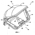
- FIG. 1 illustrates a perspective view of a current embodiment of the invention, generally indicated at 100, of a light source structure constructed according to principles of the invention.
- Light source structure 100 may generally be characterized as a lamp.
- Lamp 100 is powered by electricity, and functions to provide illumination to a work area disposed a distance from the lamp front, generally indicated at 102.
- the work area illuminated by lamp 100 is shadow-free, and appears relatively uniform in illumination color and intensity.
- the illuminated target work area is considered to have an approximately flat footprint and a depth normal to that footprint. That is, the illuminated region is generally structured to encompass a volume disposed proximate the footprint.
- Illustrated lamp 100 can include an attachment structure (not shown) operable to connect lamp 100 to suspension structure in the work area. Such an attachment structure is typically attached at a back 106 of lamp 100, although any convenient arrangement is operable.
- Typical suspension structure in a dental operatory permits a user to orient the lamp in space operably to aim the light output of lamp 100 at the desired target area.
- Certain embodiments of the invention provide a lamp having reduced weight and/or intrusive volume compared to commercially available lamps. Such reduced weight lamps permit a corresponding reduction in mass of the lamp suspension arrangement, thereby increasing ease of manipulation of the lamp to orient its output toward a target.
- a front shield (not shown) can be provided as a protective cover to block migration of dust and contaminated aerosols into the lamp interior.
- a front surface of such a shield may be structured to provide an easily cleanable surface, whereby to maintain sterility of the operatory area.
- the shield may incorporate one or more lenses to focus, or otherwise modify, the light output of lamp 100.
- a shield made from Lexan®, or other similar optically useful and formable material can be provided to completely encase the front of a dental lamp to resist contamination of, and to facilitate cleaning of, the lamp.
- the shield may be injection molded and may include focusing lenses.
- the shield, or a portion of lamp housing 114 can be hinged, or otherwise openable by a user, to provide access to the interior of lamp 100 for maintenance or replacement of a light generating element.
- an LED 118 emits light indicated by a plurality of rays 120.
- An operable LED can include a 3 watt LED, such as that sold by Lumileds Lighting US, LLC under the Brand name Luxeon, part number LXHL-LW3C.
- a reflective element is provided to direct the LED's light output toward a target.
- reflective element 116 can be a concave aspheric reflector which collects the light emanating from the mixing rod and focuses it onto the plane of the patient's face ("image plane").
- the reflector surface contour can be a simple 2D ellipse section revolved around the central optical axis.
- a focusing lens 122 may be included in an arrangement effective to collimate rays 120 and further direct them to an illuminated area indicated at 126.
- area 126 corresponds to the target footprint of the lamp 100. In such case, it is desired that the illumination emitted from each module 108 is substantially uniform over area 126.
- Certain rays 128 may be emitted in a direction other than desired for impingement on area 126. Such rays 128 are characterized as stray light. As indicated by the illustrated collection of rays 120, area 126 sometimes has a higher intensity of illumination at its center, and may fade to a decreased intensity near its perimeter, as discussed with reference to FIG. 4 . In another embodiment, the LED 118, mirror 122, and all associated optics are arranged in harmony to produce a substantially uniform intensity over its illuminated footprint at a selected focal distance.
- LEDs 118 are typically mounted onto a bracket 112 associated with lamp housing 114.
- the bracket 112 assembly is structured to provide simple and rapid installation and removal of LED 118, and includes connection structure for the electricity supplied to the LED and may further include a metal core circuit board 130.
- bracket 112 is further desirable for bracket 112 to be formed from a material capable of conducting heat or, alternatively, to be associated with heat conducting pipes 134.
- bracket 112 and/or heat pipe 134, together with housing 132 may be structured and arranged to dissipate any heat generated by LED 118 in a direction away from the front 102 of the lamp 100.
- heat pipe 134 is particularly desirable since a large heat sink positioned directly behind the metal core board with the heat-generating LEDs may significantly obscure the light focusing onto the image plane.
- the heat can be conducted away via heat pipes 134 to a heat sink housing positioned on the back of the reflector where it does not obscure the light.
- An exemplary heat sink housing can include heat sink fins 142.
- the heat sink fins 142 can be integral with the outer housing of the lamp and constructed of any heat conducting or dissipating material, such as cast aluminum.
- a fan can be used to draw air into a gap 144 between the reflector and the heat sink housing.
- the inside of the heat sink/housing includes fins or ribs 142 that form air channels therebetween.
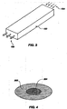
- a clear rectangular rod made of acrylic serves this function and is referred to herein as an optical light guide or a light mixing rod 136.
- the mixing rod 136 can be made out of any suitable material capable of acting as an optical light guide.
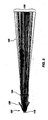
- the performance of the mixing rod 136 can be significantly enhanced with the addition of periodic features or "ripples" 150 on the outside walls of the mixing rod, as shown in FIGS. 1 and 3 . As illustrated in FIG.
- light from multiple LEDs of different colors 154 are introduced through one end of the mixing rod 136 and emanate from another end of the mixing rod 136 as a composite white light 158.
- One particular embodiment combines the light from four different colored LEDs (red, blue, green, and amber) to produce white light.
- the character of the white light can be changed. Specifically, white light with coordinated color temperatures (CCTs) of 4200°K and 5000 °K can be produced while maintaining a high color rendering index (CRI), typically in excess of 75. Blue light typically occurs in the peak wavelength range of 445 nm to 465 nm.
- CCTs coordinated color temperatures
- CRI color rendering index
- Green light typically occurs in the dominant wavelength range of 520 nm to 550 nm, amber light in the range of 584 nm to 597 nm, and red light in the range of 613 nm to 645 nm.
- a rod support 138 can be used to secure mixing rod 136 in place.
- LEDs of each color can be mounted using reflow surface mount techniques to achieve optimum optical density.
- a conventional metal core board (MCB) 130 can be used.
- a convention fiberglass laminate (FR4) printed circuit board (PCB) material can be used.
- LEDs, particularly red and amber LEDs, have the characteristic that their light output decreases significantly as their temperature raises. Heat management can be critical to maintaining optimum light output and therefore the proper ratios of light intensity to maintain the desired CCT and CRL
- the lamp 100 of the present invention includes a number of different operating modes which provide different light characteristics, as described in Table 1.
- Table 1 Nominal Approximate relative peak intensity Mode CCT (°K) CRI Blue Green Amber Red Comments "Cool white” 5,000 70+ 0.72 0.70 0.75 1.00 Meets European user preference for cooler white light.
- No-cure" N/A N/A -0 0.30 0.60 1.00 Greatly reduced flux below 500 nm will not cure dental adhesives.
- each color is independently characterized for peak wavelength, spectral spread (full width half max), and illuminance (lux) at the image plane at a predetermined maximum current.
- spectral spread full width half max
- illuminance lux
- test software based on both theoretical and empirical predictions, these values are used to generate a table of duty cycles for each wavelength at each of the three operating conditions: 4200K, 5000K, and "No Cure" modes at start up (board temperature equal to ambient temperature).
- These tables then can be stored on an electronic memory device (chip) that matches the serial number of the lamp.
- the PWM controller looks up the duty cycle table on the memory chip and sets the duty cycles accordingly when the lamp is first started.
- the test software algorithm can also produce and store duty cycle tables for the full range of operating board temperatures, as discussed in more detail below.
- temperature compensation or measurement may be included. Since each color LED has a different sensitivity to heat, a compensation algorithm can be used to set the drive current values for each color as a function of temperature. The compensation algorithm may be adapted to assume that LEDs of a given color do not exhibit significant differences in temperature sensitivity. As a result, each lamp need not be characterized thermally but rather may depend on the theoretical and empirically determined temperature relationships in the algorithm. A thermistor on the LED circuit board may also be included to measure actual board temperature from which the LED temperature can be derived, based on previously determined empirical values, and the current to each LED color can be adjusted accordingly by software.
- a dental operatory lamp used to illuminate an operating area comprises a housing having a front directed toward the operating area and a rear away from the operating area, and a reflector module located at the rear of the housing.
- An electrical power supply is provided for supplying electrical power to the LEDs for illuminating the LEDs, with the power supply being selectively operable to provide an intensity adjustment for the LEDs.
- the electrical power supply can be selectively operable to control the level of power transmitted to each LED independent of the level of power transmitted to the other LEDs.
- the lamp can be configured to have a variable color output.
- the intensity adjustment can range from 0 to about 2500 FC.
- the intensity adjustment can be continuous throughout its range of adjustments or, alternatively, can be adjustable at discrete settings within its range of adjustments.
- the lamp may further include a microprocessor in communication with the LEDs to control the level of power transmitted to the LEDs, and thus the output intensity of the light from the lamp.
- Suitable microprocessors for use with the present invention are well known in the art and include, but are not limited to, any programmable digital electronic component that incorporates the functions of a central processing unit (CPU) on a single semiconducting integrated circuit (IC).
- a dental operatory lamp used to illuminate an operating area comprises a housing having a front directed toward the operating area and a rear facing away from the operating area.
- a plurality of light emitting diodes (LEDs) can be included.
- An adapter configured for receiving at least one non-light emitting diode (non-LED) light source is located within the housing.
- the at least one non-LED light source may consist of a group of lights that can be selected from, for example, Quartz halogen, tungsten halogen, incandescent, xenon, fluorescent, fiber optics, gas plasma, laser, ultraviolet, and blue light.
- the at least one non-LED light source may also include the group of lights selected from, for example, dental curing light, oral cancer screening light, decay detection (cavities and caries) blood detection sterilization and tooth whitening light.
- a particular embodiment of the invention includes a dental operatory lamp used to illuminate an operating area having a housing with a front directed toward the operating area and a rear away from the operating area.
- the LEDs 118 are positioned with their longitudinal axes aligned toward predetermined points on the reflective element 116 for directing the light from the LEDs 118 toward the front of the lamp in a pattern that focuses light from the lamp to a central area of illumination of high intensity 204, with significantly reduced intensity illumination 202 outside the central area, as shown in FIG. 4 .
- Particular representative patterns of focused light emanating from the dental operatory lamps of the present invention include, for example, a pattern of focused light that can be elliptically shaped and may be about 3 inches by about 6 inches (7.62 cm by about 15.24 cm) in size.
- the reduced intensity illumination 202 outside the central area of illumination 204 decreases in intensity by 50% of a maximum intensity relative to the central area of illumination of high intensity.
- the central area of illumination of high intensity 204 can have a pattern size of at least 50 mm by 25 mm.
- the reduced intensity illumination 202 outside the central area can be configured to decrease in intensity progressively and smoothly relative to the central area of illumination of high intensity:
- the pattern can be configured to have a brightness of greater than about 20,000 Lux at a focus height of 700 mm from a target.
- the illumination on the central area of illumination of high intensity 204 at a distance of 60 mm can be configured to be less than about 1200 Lux.
- Illumination at the maximum level of the dental operating light in the spectral region of 180 nm to 400 nm can be configured to not exceed 0.008 W/m2.
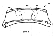
- a dental operatory lamp used to illuminate an operating area includes a lamp assembly 208 having a front 210 directed toward the operating area and a rear 212 away from the operating area.
- a reflector module 220 can be located within the lamp assembly 208, and more specifically, can be located at the rear 212 of the lamp assembly 208.
- a plurality of light emitting diodes (LEDs) can optionally be located in a reflector module 222.
- a light mixing rod (not shown) may be included as part of the reflector module 222 to produce homogenous light from the multiple LEDs of different colors.
- the lamp assembly 208 can include a curved or faceted interior reflective surface 220.
- the LEDs can be directed toward the curved or faceted interior reflective surface 220 for directing the light from the LEDs toward the front 210 of the lamp in a pattern that focuses light from the lamp to a central area of illumination of high intensity, with significantly reduced intensity illumination outside the central area.
- the reduced intensity illumination outside the central area can be configured to decrease in intensity by 50% of a maximum intensity relative to the central area of illumination of high intensity.
- the reduced intensity illumination outside the central area may be configured to decrease in intensity progressively and smoothly relative to the central area of illumination of high intensity.
- the light pattern can have a brightness of greater than about 20,000 Lux at a focus height of 700 mm from a target.
- the illumination on the central area of illumination of high intensity at a distance of 60 mm may be less than about 1200 Lux.
- the illumination at the maximum level of the dental operating light in the spectral region of 180 nm to 400 nm may be configured to not exceed 0.008 W/m 2 .
- the lamp 100 of the present invention allows the user to set various chromaticity settings, such as sunlight equivalent D65 or simulated fluorescent lighting for improved dental shade matching. It also allows the addition of thermal, color, or intensity feedback to better maintain light characteristics over the life of the product, and permits adjustment of light intensity independent of color setting.
- the lamp 100 also is adapted to provide different configurations and forms of color mixing light guides. Specifically, the lamp 100 provides a user selectable mode with reduced irradiance in the near UV and blue wavelengths to allow adequate illumination while not initiating curing of UV-curable dental composites and adhesives.
- the lamp design can provide longer life through use of LEDs instead of incandescent bulbs and which can be further achieved through use of heat pipes, finned rear housing and fan cooling which maintain low LED temperature even at high currents.
- a dental operatory lamp used to illuminate an operating area may comprise: a thermally conductive housing having a front directed toward the operating area and a rear away from the operating area, a generally elliptical reflector located on the rear of the thermally conductive housing, at least one heat pipe, a plurality of color LEDs projecting light toward the elliptical reflector, the plurality of LEDs being in thermal contact with the at least one heat pipe and an optical light guide for combining light from said LEDs.
- the plurality of color LEDs may comprise LEDs that emit at least three colors.
- the plurality of color LEDs may comprise LEDs that emit red, blue, green, and amber light wavelengths.
- the optical light guide may produce at least three operating modes with different light characteristics.
- the at least three operating modes may include a cool white mode, a cool white mode, and a no cure mode.
- the thermally conductive housing may comprise cooling air channels formed between the reflector and the rear of the thermally conductive housing.
- the cooling air channels may be formed by fins.
- the generally elliptical reflector may be shaped to direct the light from the LEDs toward the front of the lamp in a pattern that focuses light from the lamp to a central area of illumination of high intensity, with significantly reduced intensity illumination outside the central area.
- the optical light guide may direct the light from the LEDs toward the front of the lamp in a pattern that focuses light from the lamp to a central area of illumination of high intensity, with significantly reduced intensity illumination outside the central area.
- the dental operatory lamp may further comprise an electrical power supply for supplying electrical power to the LEDs for illuminating the LEDs, with the power supply being selectively operable to provide an intensity adjustment for the LEDs.
- the dental operatory lamp may further comprise an adapter configured for receiving at least one non-light emitting diode (non-LED) light source within the housing.
- non-LED non-light emitting diode
- the dental operatory lamp may further comprise a fan located at the rear of the of the thermally conductive housing.
- the optical light guide may comprise periodic features on an exterior surface thereof.
- the dental operatory lamp may produce white light with coordinated color temperatures of between 4200°K and 5000°K, and maintaining a color rendering index in excess of 75.
Landscapes
- Engineering & Computer Science (AREA)
- General Engineering & Computer Science (AREA)
- Dental Tools And Instruments Or Auxiliary Dental Instruments (AREA)
- Non-Portable Lighting Devices Or Systems Thereof (AREA)
Claims (5)
- Eine zahnärztliche Operationsleuchte (100), die verwendet wird, um einen Operationsbereich zu beleuchten, umfassend:eine Vielzahl von Farb-LEDs (118); undeine optische Lichtführung (136) zum Kombinieren des Lichts von den LEDs;dadurch gekennzeichnet, dass die Leuchte mindestens zwei vom Anwender auswählbare Lichtspektren bereitstellt, wobei eines der Spektren durch die Vielzahl von Farb-LEDs erzeugt wird und weißes Licht mit einer Farbtemperatur im Bereich zwischen 4000° K und 6000° K bereitstellt und ein Spektrum von einem oder mehr aus der Vielzahl von Farb-LEDs erzeugt wird und eine reduzierte Ausgabe im Wellenlängenbereich zwischen 400 und 500 nm aufweist.
- Die zahnärztliche Operationsleuchte von Anspruch 1, wobei die vom Anwender auswählbaren Lichtspektren verschiedene Verhältnisse von mindestens drei Farben, die von den Farb-LEDs ausgestrahlt werden, umfassen.
- Die zahnärztliche Operationsleuchte von Anspruch 1, wobei die vom Anwender auswählbaren Spektren verschiedene Verhältnisse von rotem, blauen, grünen und gelbem Licht, das von den Farb-LEDs ausgestrahlt wird, umfassen.
- Die zahnärztliche Operationsleuchte von Anspruch 1, ferner umfassend:ein Gehäuse (114, 208) mit einer auf den Operationsbereich gerichteten Vorderseite (102, 210) und einer vom Operationsbereich abgewandten Rückseite (106, 212); undein Reflektormodul (116, 220), das sich an der Rückseite des Gehäuses befindet;wobei die Vielzahl von Farblicht emittierenden Dioden (LEDs) sich auf dem Reflektormodul befindet; unddie optische Lichtführung konfiguriert ist, um das Licht von den Farb-LEDs auf die Vorderseite der Leuchte in einem Muster zur richten, das weißes Licht von der Leuchte auf einen Zentralbereich hoher Beleuchtungsstärke fokussiert, wobei die Beleuchtungsstärke außerhalb des Zentralbereichs signifikant reduziert ist.
- Die zahnärztliche Operationsleuchte von Anspruch 4, wobei die optische Lichtführung mindestens drei Betriebsarten mit verschiedenen Lichteigenschaften erzeugt.
Applications Claiming Priority (2)
| Application Number | Priority Date | Filing Date | Title |
|---|---|---|---|
| US11/867,876 US20080025013A1 (en) | 2005-05-02 | 2007-10-05 | Led-powered dental operatory light |
| EP08835676.1A EP2203105B1 (de) | 2007-10-05 | 2008-08-14 | Auf led basierende lampe mit veränderlicher chromatizität für zahnärztliche untersuchungen |
Related Parent Applications (2)
| Application Number | Title | Priority Date | Filing Date |
|---|---|---|---|
| EP08835676.1 Division | 2008-08-14 | ||
| EP08835676.1A Division EP2203105B1 (de) | 2007-10-05 | 2008-08-14 | Auf led basierende lampe mit veränderlicher chromatizität für zahnärztliche untersuchungen |
Publications (2)
| Publication Number | Publication Date |
|---|---|
| EP2649930A1 EP2649930A1 (de) | 2013-10-16 |
| EP2649930B1 true EP2649930B1 (de) | 2015-06-10 |
Family
ID=40527429
Family Applications (2)
| Application Number | Title | Priority Date | Filing Date |
|---|---|---|---|
| EP08835676.1A Active EP2203105B1 (de) | 2007-10-05 | 2008-08-14 | Auf led basierende lampe mit veränderlicher chromatizität für zahnärztliche untersuchungen |
| EP13176201.5A Active EP2649930B1 (de) | 2007-10-05 | 2008-08-14 | Auf led basierende lampe mit veränderlicher chromatizität für zahnärztliche untersuchungen |
Family Applications Before (1)
| Application Number | Title | Priority Date | Filing Date |
|---|---|---|---|
| EP08835676.1A Active EP2203105B1 (de) | 2007-10-05 | 2008-08-14 | Auf led basierende lampe mit veränderlicher chromatizität für zahnärztliche untersuchungen |
Country Status (7)
| Country | Link |
|---|---|
| US (1) | US20080025013A1 (de) |
| EP (2) | EP2203105B1 (de) |
| AU (1) | AU2008307694B2 (de) |
| BR (1) | BRPI0816491A2 (de) |
| CA (1) | CA2701728C (de) |
| ES (2) | ES2430617T3 (de) |
| WO (1) | WO2009045251A1 (de) |
Cited By (1)
| Publication number | Priority date | Publication date | Assignee | Title |
|---|---|---|---|---|
| US10488036B2 (en) | 2016-05-11 | 2019-11-26 | Carl Zeiss Meditec Ag | Systems and methods for illuminating an object field during a processing process of a light curing plastic |
Families Citing this family (12)
| Publication number | Priority date | Publication date | Assignee | Title |
|---|---|---|---|---|
| US8016470B2 (en) | 2007-10-05 | 2011-09-13 | Dental Equipment, Llc | LED-based dental exam lamp with variable chromaticity |
| US8459852B2 (en) * | 2007-10-05 | 2013-06-11 | Dental Equipment, Llc | LED-based dental exam lamp |
| DE102008027252A1 (de) | 2008-06-06 | 2009-12-17 | Zett Optics Gmbh | Dentalleuchte |
| US9642687B2 (en) | 2010-06-15 | 2017-05-09 | The Procter & Gamble Company | Methods for whitening teeth |
| US10491357B2 (en) * | 2010-07-12 | 2019-11-26 | Entropic Communications Llc | Method and apparatus for using dynamic subchannels in a communications network |
| US8777451B2 (en) * | 2010-10-20 | 2014-07-15 | Air Motion Systems, Inc. | Device for uniform, large area flood exposure with LEDs |
| US9500340B2 (en) | 2011-10-25 | 2016-11-22 | A-Dec, Inc. | Dental light using LEDs |
| USD663889S1 (en) | 2011-10-25 | 2012-07-17 | A-Dec, Inc. | Handle of a dental light |
| USD663886S1 (en) | 2011-10-25 | 2012-07-17 | A-Dec, Inc. | Body of a dental light |
| USD663887S1 (en) | 2011-10-25 | 2012-07-17 | A-Dec, Inc. | Front face of a dental light shield |
| US8525441B2 (en) * | 2011-12-06 | 2013-09-03 | LT Lighting (Taiwan) Corp. | Lamp powering technology |
| US9207484B2 (en) | 2012-09-26 | 2015-12-08 | Apple Inc. | Computer LED bar and thermal architecture features |
Family Cites Families (28)
| Publication number | Priority date | Publication date | Assignee | Title |
|---|---|---|---|---|
| US3290496A (en) * | 1962-10-17 | 1966-12-06 | Arthur I Appleton | Lamp fixtures |
| US4298911A (en) * | 1979-11-30 | 1981-11-03 | Pichel Industries, Inc. | Lighting device for creating public attraction |
| US4608622A (en) * | 1983-12-28 | 1986-08-26 | Dentsply Research & Development Corp. | Multi-function light source |
| GB9011665D0 (en) | 1990-03-21 | 1990-07-11 | Stephenson Group | Recycling of fibre products |
| US5406176A (en) * | 1994-01-12 | 1995-04-11 | Aurora Robotics Limited | Computer controlled stage lighting system |
| FR2720752B1 (fr) | 1994-06-07 | 1996-10-31 | Rhone Poulenc Chimie | Composition silicone réticulable ou réticulée, antiadhérente et imprimable. |
| US5624569A (en) | 1996-01-23 | 1997-04-29 | Nalco Chemical Company | Clarification of deinking process water |
| EP0745648A3 (de) | 1995-06-01 | 1997-12-10 | Dow Corning Corporation | Stabile dispergierbare Siliconmassen |
| US6120164A (en) * | 1997-11-25 | 2000-09-19 | Luminaria Ltd. | Multiple lamp lighting fixture |
| US6200134B1 (en) * | 1998-01-20 | 2001-03-13 | Kerr Corporation | Apparatus and method for curing materials with radiation |
| US6439888B1 (en) * | 1999-05-03 | 2002-08-27 | Pls Liquidating Llc | Optical source and method |
| US6290368B1 (en) * | 1999-05-21 | 2001-09-18 | Robert A. Lehrer | Portable reading light device |
| US20050099824A1 (en) * | 2000-08-04 | 2005-05-12 | Color Kinetics, Inc. | Methods and systems for medical lighting |
| TW512214B (en) * | 2000-01-07 | 2002-12-01 | Koninkl Philips Electronics Nv | Luminaire |
| US7320593B2 (en) * | 2000-03-08 | 2008-01-22 | Tir Systems Ltd. | Light emitting diode light source for curing dental composites |
| US20030215766A1 (en) * | 2002-01-11 | 2003-11-20 | Ultradent Products, Inc. | Light emitting systems and kits that include a light emitting device and one or more removable lenses |
| GB0217197D0 (en) | 2002-07-24 | 2002-09-04 | Dow Corning | Method of deinking |
| MXPA05001029A (es) * | 2002-07-25 | 2005-09-12 | Jonathan S Dahm | Metodo y aparato para utilizar diodos emisores de luz para curacion. |
| BR0316715A (pt) * | 2002-11-19 | 2005-10-18 | Den Mat Corp | Guia dental com luz |
| US6991356B2 (en) * | 2002-12-20 | 2006-01-31 | Efraim Tsimerman | LED curing light |
| KR100643516B1 (ko) * | 2003-05-06 | 2006-11-10 | 가부시키가이샤 모리타 세이사쿠쇼 | 의료용 광조사장치 |
| US6955444B2 (en) * | 2003-11-12 | 2005-10-18 | Visiled, Inc. | Surgical headlight |
| CN1977127B (zh) * | 2004-03-30 | 2010-08-04 | 照明管理解决方案公司 | 用于改进的照明区域填充的设备和方法 |
| DE102006004995A1 (de) * | 2005-02-01 | 2006-10-19 | Schott Ag | Leuchte für zahnärztliche oder chirurgische Verwendung |
| US7210814B2 (en) * | 2005-04-29 | 2007-05-01 | Ultradent Products, Inc. | Dental curing light with specially arranged LEDs |
| US7425077B2 (en) * | 2005-05-02 | 2008-09-16 | Pelton & Crane | LED-powered dental operatory light |
| EP1741975B1 (de) * | 2005-07-05 | 2011-09-07 | Frowein EZH GmbH | Operationsleuchte |
| US20070031777A1 (en) * | 2005-08-03 | 2007-02-08 | Bwt Property, Inc. | Multifunctional Dental Apparatus |
-
2007
- 2007-10-05 US US11/867,876 patent/US20080025013A1/en not_active Abandoned
-
2008
- 2008-08-14 AU AU2008307694A patent/AU2008307694B2/en not_active Ceased
- 2008-08-14 EP EP08835676.1A patent/EP2203105B1/de active Active
- 2008-08-14 WO PCT/US2008/009768 patent/WO2009045251A1/en not_active Ceased
- 2008-08-14 EP EP13176201.5A patent/EP2649930B1/de active Active
- 2008-08-14 CA CA2701728A patent/CA2701728C/en active Active
- 2008-08-14 BR BRPI0816491-6A2A patent/BRPI0816491A2/pt not_active IP Right Cessation
- 2008-08-14 ES ES08835676T patent/ES2430617T3/es active Active
- 2008-08-14 ES ES13176201.5T patent/ES2539472T3/es active Active
Cited By (1)
| Publication number | Priority date | Publication date | Assignee | Title |
|---|---|---|---|---|
| US10488036B2 (en) | 2016-05-11 | 2019-11-26 | Carl Zeiss Meditec Ag | Systems and methods for illuminating an object field during a processing process of a light curing plastic |
Also Published As
| Publication number | Publication date |
|---|---|
| CA2701728A1 (en) | 2009-04-09 |
| EP2649930A1 (de) | 2013-10-16 |
| EP2203105A1 (de) | 2010-07-07 |
| AU2008307694B2 (en) | 2013-03-21 |
| AU2008307694A1 (en) | 2009-04-09 |
| ES2430617T3 (es) | 2013-11-21 |
| CA2701728C (en) | 2014-12-23 |
| BRPI0816491A2 (pt) | 2015-03-10 |
| WO2009045251A1 (en) | 2009-04-09 |
| EP2203105A4 (de) | 2011-05-25 |
| EP2203105B1 (de) | 2013-10-09 |
| ES2539472T3 (es) | 2015-07-01 |
| US20080025013A1 (en) | 2008-01-31 |
Similar Documents
| Publication | Publication Date | Title |
|---|---|---|
| US8388205B2 (en) | LED-based dental exam lamp with variable chromaticity | |
| US10386055B2 (en) | LED-based dental exam lamp | |
| EP2203105B1 (de) | Auf led basierende lampe mit veränderlicher chromatizität für zahnärztliche untersuchungen | |
| US9222628B2 (en) | Color temperature tunable LED-based lamp module | |
| US10767847B2 (en) | Photographic lighting device | |
| US20070097703A1 (en) | Integral solid-state luminaire with dual light paths and coaxial optics | |
| US7425077B2 (en) | LED-powered dental operatory light | |
| US20060002135A1 (en) | Dental lamp particularly for medical and dental surgeries | |
| WO2009045223A1 (en) | Led-powered dental operatory light | |
| AU2013200374B2 (en) | LED-Based Dental Exam Lamp with Variable Chromaticity | |
| JP3084178U (ja) | 無影灯 | |
| CN105413064B (zh) | 一种黄疸治疗仪 | |
| CN201875615U (zh) | 小型led内窥镜照明光源 |
Legal Events
| Date | Code | Title | Description |
|---|---|---|---|
| PUAI | Public reference made under article 153(3) epc to a published international application that has entered the european phase |
Free format text: ORIGINAL CODE: 0009012 |
|
| AC | Divisional application: reference to earlier application |
Ref document number: 2203105 Country of ref document: EP Kind code of ref document: P |
|
| AK | Designated contracting states |
Kind code of ref document: A1 Designated state(s): AT BE BG CH CY CZ DE DK EE ES FI FR GB GR HR HU IE IS IT LI LT LU LV MC MT NL NO PL PT RO SE SI SK TR |
|
| AX | Request for extension of the european patent |
Extension state: AL BA MK RS |
|
| 17P | Request for examination filed |
Effective date: 20140415 |
|
| RBV | Designated contracting states (corrected) |
Designated state(s): AT BE BG CH CY CZ DE DK EE ES FI FR GB GR HR HU IE IS IT LI LT LU LV MC MT NL NO PL PT RO SE SI SK TR |
|
| GRAP | Despatch of communication of intention to grant a patent |
Free format text: ORIGINAL CODE: EPIDOSNIGR1 |
|
| RIC1 | Information provided on ipc code assigned before grant |
Ipc: F21Y 113/00 20060101ALN20141029BHEP Ipc: F21W 131/202 20060101ALN20141029BHEP Ipc: F21V 13/04 20060101ALI20141029BHEP Ipc: A61B 1/06 20060101AFI20141029BHEP Ipc: F21Y 101/02 20060101ALN20141029BHEP |
|
| INTG | Intention to grant announced |
Effective date: 20141124 |
|
| GRAS | Grant fee paid |
Free format text: ORIGINAL CODE: EPIDOSNIGR3 |
|
| GRAP | Despatch of communication of intention to grant a patent |
Free format text: ORIGINAL CODE: EPIDOSNIGR1 |
|
| RAP1 | Party data changed (applicant data changed or rights of an application transferred) |
Owner name: KAVO DENTAL TECHNOLOGIES, LLC |
|
| INTG | Intention to grant announced |
Effective date: 20150407 |
|
| RIC1 | Information provided on ipc code assigned before grant |
Ipc: F21Y 101/02 20060101ALN20150323BHEP Ipc: F21W 131/202 20060101ALN20150323BHEP Ipc: F21Y 113/00 20060101ALN20150323BHEP Ipc: A61B 1/06 20060101AFI20150323BHEP Ipc: F21V 13/04 20060101ALI20150323BHEP |
|
| GRAA | (expected) grant |
Free format text: ORIGINAL CODE: 0009210 |
|
| AC | Divisional application: reference to earlier application |
Ref document number: 2203105 Country of ref document: EP Kind code of ref document: P |
|
| AK | Designated contracting states |
Kind code of ref document: B1 Designated state(s): AT BE BG CH CY CZ DE DK EE ES FI FR GB GR HR HU IE IS IT LI LT LU LV MC MT NL NO PL PT RO SE SI SK TR |
|
| REG | Reference to a national code |
Ref country code: GB Ref legal event code: FG4D |
|
| REG | Reference to a national code |
Ref country code: CH Ref legal event code: EP |
|
| REG | Reference to a national code |
Ref country code: ES Ref legal event code: FG2A Ref document number: 2539472 Country of ref document: ES Kind code of ref document: T3 Effective date: 20150701 |
|
| REG | Reference to a national code |
Ref country code: AT Ref legal event code: REF Ref document number: 730561 Country of ref document: AT Kind code of ref document: T Effective date: 20150715 |
|
| REG | Reference to a national code |
Ref country code: DE Ref legal event code: R096 Ref document number: 602008038559 Country of ref document: DE |
|
| REG | Reference to a national code |
Ref country code: IE Ref legal event code: FG4D |
|
| PG25 | Lapsed in a contracting state [announced via postgrant information from national office to epo] |
Ref country code: NO Free format text: LAPSE BECAUSE OF FAILURE TO SUBMIT A TRANSLATION OF THE DESCRIPTION OR TO PAY THE FEE WITHIN THE PRESCRIBED TIME-LIMIT Effective date: 20150910 Ref country code: LT Free format text: LAPSE BECAUSE OF FAILURE TO SUBMIT A TRANSLATION OF THE DESCRIPTION OR TO PAY THE FEE WITHIN THE PRESCRIBED TIME-LIMIT Effective date: 20150610 |
|
| REG | Reference to a national code |
Ref country code: AT Ref legal event code: MK05 Ref document number: 730561 Country of ref document: AT Kind code of ref document: T Effective date: 20150610 |
|
| REG | Reference to a national code |
Ref country code: NL Ref legal event code: MP Effective date: 20150610 |
|
| PG25 | Lapsed in a contracting state [announced via postgrant information from national office to epo] |
Ref country code: LV Free format text: LAPSE BECAUSE OF FAILURE TO SUBMIT A TRANSLATION OF THE DESCRIPTION OR TO PAY THE FEE WITHIN THE PRESCRIBED TIME-LIMIT Effective date: 20150610 Ref country code: GR Free format text: LAPSE BECAUSE OF FAILURE TO SUBMIT A TRANSLATION OF THE DESCRIPTION OR TO PAY THE FEE WITHIN THE PRESCRIBED TIME-LIMIT Effective date: 20150911 Ref country code: BG Free format text: LAPSE BECAUSE OF FAILURE TO SUBMIT A TRANSLATION OF THE DESCRIPTION OR TO PAY THE FEE WITHIN THE PRESCRIBED TIME-LIMIT Effective date: 20150910 |
|
| PG25 | Lapsed in a contracting state [announced via postgrant information from national office to epo] |
Ref country code: EE Free format text: LAPSE BECAUSE OF FAILURE TO SUBMIT A TRANSLATION OF THE DESCRIPTION OR TO PAY THE FEE WITHIN THE PRESCRIBED TIME-LIMIT Effective date: 20150610 |
|
| PG25 | Lapsed in a contracting state [announced via postgrant information from national office to epo] |
Ref country code: IS Free format text: LAPSE BECAUSE OF FAILURE TO SUBMIT A TRANSLATION OF THE DESCRIPTION OR TO PAY THE FEE WITHIN THE PRESCRIBED TIME-LIMIT Effective date: 20151010 Ref country code: PL Free format text: LAPSE BECAUSE OF FAILURE TO SUBMIT A TRANSLATION OF THE DESCRIPTION OR TO PAY THE FEE WITHIN THE PRESCRIBED TIME-LIMIT Effective date: 20150610 Ref country code: PT Free format text: LAPSE BECAUSE OF FAILURE TO SUBMIT A TRANSLATION OF THE DESCRIPTION OR TO PAY THE FEE WITHIN THE PRESCRIBED TIME-LIMIT Effective date: 20151012 Ref country code: SK Free format text: LAPSE BECAUSE OF FAILURE TO SUBMIT A TRANSLATION OF THE DESCRIPTION OR TO PAY THE FEE WITHIN THE PRESCRIBED TIME-LIMIT Effective date: 20150610 Ref country code: CZ Free format text: LAPSE BECAUSE OF FAILURE TO SUBMIT A TRANSLATION OF THE DESCRIPTION OR TO PAY THE FEE WITHIN THE PRESCRIBED TIME-LIMIT Effective date: 20150610 Ref country code: AT Free format text: LAPSE BECAUSE OF FAILURE TO SUBMIT A TRANSLATION OF THE DESCRIPTION OR TO PAY THE FEE WITHIN THE PRESCRIBED TIME-LIMIT Effective date: 20150610 Ref country code: RO Free format text: LAPSE BECAUSE OF NON-PAYMENT OF DUE FEES Effective date: 20150610 |
|
| REG | Reference to a national code |
Ref country code: DE Ref legal event code: R097 Ref document number: 602008038559 Country of ref document: DE |
|
| PG25 | Lapsed in a contracting state [announced via postgrant information from national office to epo] |
Ref country code: LU Free format text: LAPSE BECAUSE OF FAILURE TO SUBMIT A TRANSLATION OF THE DESCRIPTION OR TO PAY THE FEE WITHIN THE PRESCRIBED TIME-LIMIT Effective date: 20150814 Ref country code: MC Free format text: LAPSE BECAUSE OF FAILURE TO SUBMIT A TRANSLATION OF THE DESCRIPTION OR TO PAY THE FEE WITHIN THE PRESCRIBED TIME-LIMIT Effective date: 20150610 |
|
| REG | Reference to a national code |
Ref country code: CH Ref legal event code: PL |
|
| PLBE | No opposition filed within time limit |
Free format text: ORIGINAL CODE: 0009261 |
|
| STAA | Information on the status of an ep patent application or granted ep patent |
Free format text: STATUS: NO OPPOSITION FILED WITHIN TIME LIMIT |
|
| PG25 | Lapsed in a contracting state [announced via postgrant information from national office to epo] |
Ref country code: DK Free format text: LAPSE BECAUSE OF FAILURE TO SUBMIT A TRANSLATION OF THE DESCRIPTION OR TO PAY THE FEE WITHIN THE PRESCRIBED TIME-LIMIT Effective date: 20150610 Ref country code: LI Free format text: LAPSE BECAUSE OF NON-PAYMENT OF DUE FEES Effective date: 20150831 Ref country code: CH Free format text: LAPSE BECAUSE OF NON-PAYMENT OF DUE FEES Effective date: 20150831 |
|
| 26N | No opposition filed |
Effective date: 20160311 |
|
| PG25 | Lapsed in a contracting state [announced via postgrant information from national office to epo] |
Ref country code: SI Free format text: LAPSE BECAUSE OF FAILURE TO SUBMIT A TRANSLATION OF THE DESCRIPTION OR TO PAY THE FEE WITHIN THE PRESCRIBED TIME-LIMIT Effective date: 20150610 |
|
| REG | Reference to a national code |
Ref country code: IE Ref legal event code: MM4A |
|
| PG25 | Lapsed in a contracting state [announced via postgrant information from national office to epo] |
Ref country code: IE Free format text: LAPSE BECAUSE OF NON-PAYMENT OF DUE FEES Effective date: 20150814 |
|
| REG | Reference to a national code |
Ref country code: FR Ref legal event code: PLFP Year of fee payment: 9 |
|
| PG25 | Lapsed in a contracting state [announced via postgrant information from national office to epo] |
Ref country code: BE Free format text: LAPSE BECAUSE OF FAILURE TO SUBMIT A TRANSLATION OF THE DESCRIPTION OR TO PAY THE FEE WITHIN THE PRESCRIBED TIME-LIMIT Effective date: 20150610 |
|
| PG25 | Lapsed in a contracting state [announced via postgrant information from national office to epo] |
Ref country code: MT Free format text: LAPSE BECAUSE OF FAILURE TO SUBMIT A TRANSLATION OF THE DESCRIPTION OR TO PAY THE FEE WITHIN THE PRESCRIBED TIME-LIMIT Effective date: 20150610 |
|
| PG25 | Lapsed in a contracting state [announced via postgrant information from national office to epo] |
Ref country code: HU Free format text: LAPSE BECAUSE OF FAILURE TO SUBMIT A TRANSLATION OF THE DESCRIPTION OR TO PAY THE FEE WITHIN THE PRESCRIBED TIME-LIMIT; INVALID AB INITIO Effective date: 20080814 |
|
| PG25 | Lapsed in a contracting state [announced via postgrant information from national office to epo] |
Ref country code: NL Free format text: LAPSE BECAUSE OF FAILURE TO SUBMIT A TRANSLATION OF THE DESCRIPTION OR TO PAY THE FEE WITHIN THE PRESCRIBED TIME-LIMIT Effective date: 20150610 Ref country code: SE Free format text: LAPSE BECAUSE OF FAILURE TO SUBMIT A TRANSLATION OF THE DESCRIPTION OR TO PAY THE FEE WITHIN THE PRESCRIBED TIME-LIMIT Effective date: 20150610 Ref country code: CY Free format text: LAPSE BECAUSE OF FAILURE TO SUBMIT A TRANSLATION OF THE DESCRIPTION OR TO PAY THE FEE WITHIN THE PRESCRIBED TIME-LIMIT Effective date: 20150610 |
|
| PG25 | Lapsed in a contracting state [announced via postgrant information from national office to epo] |
Ref country code: HR Free format text: LAPSE BECAUSE OF FAILURE TO SUBMIT A TRANSLATION OF THE DESCRIPTION OR TO PAY THE FEE WITHIN THE PRESCRIBED TIME-LIMIT Effective date: 20150610 |
|
| REG | Reference to a national code |
Ref country code: FR Ref legal event code: PLFP Year of fee payment: 10 |
|
| PG25 | Lapsed in a contracting state [announced via postgrant information from national office to epo] |
Ref country code: TR Free format text: LAPSE BECAUSE OF FAILURE TO SUBMIT A TRANSLATION OF THE DESCRIPTION OR TO PAY THE FEE WITHIN THE PRESCRIBED TIME-LIMIT Effective date: 20150610 |
|
| REG | Reference to a national code |
Ref country code: FR Ref legal event code: PLFP Year of fee payment: 11 |
|
| RIC2 | Information provided on ipc code assigned after grant |
Ipc: F21V 13/04 20060101ALI20150323BHEP Ipc: F21Y 101/02 20000101ALN20150323BHEP Ipc: A61B 1/06 20060101AFI20150323BHEP Ipc: F21Y 113/00 20160101ALN20150323BHEP Ipc: F21W 131/202 20060101ALN20150323BHEP |
|
| PGFP | Annual fee paid to national office [announced via postgrant information from national office to epo] |
Ref country code: GB Payment date: 20250626 Year of fee payment: 18 |
|
| PGFP | Annual fee paid to national office [announced via postgrant information from national office to epo] |
Ref country code: FR Payment date: 20250610 Year of fee payment: 18 |
|
| PGFP | Annual fee paid to national office [announced via postgrant information from national office to epo] |
Ref country code: ES Payment date: 20250902 Year of fee payment: 18 Ref country code: FI Payment date: 20250814 Year of fee payment: 18 |
|
| PGFP | Annual fee paid to national office [announced via postgrant information from national office to epo] |
Ref country code: DE Payment date: 20250618 Year of fee payment: 18 |
|
| PGFP | Annual fee paid to national office [announced via postgrant information from national office to epo] |
Ref country code: IT Payment date: 20250722 Year of fee payment: 18 |