EP2648959B1 - Ein-/ausstiegsausschub mit bremsmitteln - Google Patents
Ein-/ausstiegsausschub mit bremsmitteln Download PDFInfo
- Publication number
- EP2648959B1 EP2648959B1 EP10794941.4A EP10794941A EP2648959B1 EP 2648959 B1 EP2648959 B1 EP 2648959B1 EP 10794941 A EP10794941 A EP 10794941A EP 2648959 B1 EP2648959 B1 EP 2648959B1
- Authority
- EP
- European Patent Office
- Prior art keywords
- embarking
- extension
- braking
- disembarking
- carrier
- Prior art date
- Legal status (The legal status is an assumption and is not a legal conclusion. Google has not performed a legal analysis and makes no representation as to the accuracy of the status listed.)
- Not-in-force
Links
- 230000003287 optical effect Effects 0.000 claims description 2
- 230000005540 biological transmission Effects 0.000 description 5
- 230000006378 damage Effects 0.000 description 5
- 230000000694 effects Effects 0.000 description 5
- 208000027418 Wounds and injury Diseases 0.000 description 2
- 238000006073 displacement reaction Methods 0.000 description 2
- 208000014674 injury Diseases 0.000 description 2
- 230000000903 blocking effect Effects 0.000 description 1
- 238000010276 construction Methods 0.000 description 1
- 230000001419 dependent effect Effects 0.000 description 1
- 238000001514 detection method Methods 0.000 description 1
Images

Classifications
-
- B—PERFORMING OPERATIONS; TRANSPORTING
- B60—VEHICLES IN GENERAL
- B60R—VEHICLES, VEHICLE FITTINGS, OR VEHICLE PARTS, NOT OTHERWISE PROVIDED FOR
- B60R3/00—Arrangements of steps or ladders facilitating access to or on the vehicle, e.g. running-boards
- B60R3/02—Retractable steps or ladders, e.g. movable under shock
-
- B—PERFORMING OPERATIONS; TRANSPORTING
- B61—RAILWAYS
- B61D—BODY DETAILS OR KINDS OF RAILWAY VEHICLES
- B61D23/00—Construction of steps for railway vehicles
- B61D23/02—Folding steps for railway vehicles, e.g. hand or mechanically actuated
-
- B—PERFORMING OPERATIONS; TRANSPORTING
- B61—RAILWAYS
- B61D—BODY DETAILS OR KINDS OF RAILWAY VEHICLES
- B61D23/00—Construction of steps for railway vehicles
- B61D23/02—Folding steps for railway vehicles, e.g. hand or mechanically actuated
- B61D23/025—Folding steps for railway vehicles, e.g. hand or mechanically actuated electrically or fluid actuated
Definitions
- the invention relates to an entry / exit device for a vehicle, in particular for a passenger transport vehicle, as used in public passenger transport.
- These entry / exit devices regularly have a back and forth between a retracted and extended position Ausschub, in the case of a linear displacement a so-called Schiebetritt, which defines, for example, in an extended position a traceable or passable area.
- These sliding steps regularly have lateral guides of the Ausschubs for attachment to a car body or vehicle frame of the vehicle.
- Offsets are used to facilitate people getting in and out of a passenger transport vehicle by bridging the gap between the vehicle and the boarding / boarding platform edge, such as platform edge.
- the horizontal gap width fluctuates, there are obstacles and forces acting on the extension against its extension direction.
- the gear driving the output can be designed self-locking, but such a force can easily lead to the destruction of the transmission.
- the belt drives that are preferred because of their low construction volume and quiet operation are particularly vulnerable, since such a stress can lead to a longitudinal expansion of the belt.
- the invention relates to an entry / exit device for a vehicle, in particular for a passenger transport vehicle, such as a public transport vehicle.
- the entry / exit device according to the invention has a back and forth between a retracted and extended position Ausschub, for example, a so-called sliding step on.
- rollers are mounted on the extension, which are guided in cart box side rails.
- a frame or housing may be provided, by means of which the guides are fastened to the vehicle.
- Generic sliding steps are for example from the EP 1923267 A1 known.
- the invention is not limited in terms of the design of the sliding step, the design of the associated enterable area and the design of the guide.
- the ejection is carried along by a driver.
- a motor and an associated transmission are also provided.
- the invention is not limited in terms of the engine and the transmission. It is preferably an electric motor, a hydraulic or pneumatic motor.
- a braking means is also provided to at least brake the Ausschub, wherein "at least” is to be understood that also blocking the Ausschubs can be provided according to the invention.
- the inventive device is characterized in that the ejection is relatively movably mounted on the driver, and the braking means are moved by at least from its release position to its braking position by the relative movement between the extension and driver. As a result, the ejection is slowed down in its movement or largely determined in its position.
- a force in particular with a component parallel to the direction of movement of the Ausschubs, prevents at least largely an adjustment of Ausschubs in its position and then excessive stress on the engine and the transmission. The drive components are thus protected.
- the extension is thus braked and prevents personal injury or damage to the extension.
- the braking means are moved by a restoring force in its release position.
- the relative movement of the extension and driver is configured so that an average release position and two braking positions corresponding to the two directions of movement of the relative movement between Ausschub and driver are provided.
- braking of the Ausschubs is provided for both directions of force.
- a positive or non-positive traction drive In order to save space for the drive and to reduce the operating noise, it is preferred in the transmission at least partially to a positive or non-positive traction drive.
- This is preferably a positive traction mechanism drive, such as a toothed belt drive.
- the driver is preferably attached to a belt of the traction mechanism drive.
- the braking means comprise a pivotable cam with one or more cams, which cooperates with the driver to generate a braking force.
- the cam generates the braking force by acting on a guide. More preferably, the cam in its braking position causes a wedging of the driver in his leadership.
- Frictional surface in the context of the invention means a relation to a smooth surface so from the surface texture changed surface that a contrast increased adhesion and / or sliding resistance between the braking means and the surface in question is caused, for example, by shape deviations of 1st to 4th order.
- the position of the braking means is detected by means of an optical, magnetic or electromechanical sensor.
- the detection signal thus generated is supplied to an electronic control unit, for example.
- this control unit generates an alarm signal.
- the invention further relates to a passenger transport vehicle having the advantageous, previously mentioned entry / exit device.
- the inventive entry-exit device 1 comprises a Ausschub 2, ie a linear guided Schiebetritt.
- This Ausschub 2 is guided on both sides parallel to the Ausschubides sides of Ausschubs 2 on the rollers 10 in an indicated guide 9, which in turn is attached to a vehicle frame, not shown.
- the drive of Ausschubs 2 is effected by a motor, not shown, and a traction mechanism, comprising a rotating toothed belt 3.
- a driver 4 is attached on the toothed belt 3.
- the driver 4 By means of the driver 4, the movement of the toothed belt 3 is transmitted to the Ausschub 2 to reciprocate it between its retracted position and its extended position. There is provided a relative movement between the driver 4 and the Ausschub 2.
Landscapes
- Engineering & Computer Science (AREA)
- Mechanical Engineering (AREA)
- Braking Arrangements (AREA)
- Motorcycle And Bicycle Frame (AREA)
Description
- Die Erfindung betrifft eine Ein-/Ausstiegsvorrichtung für ein Fahrzeug insbesondere für ein Personenbeförderungsfahrzeug, wie es im öffentlichen Personenverkehr verwendet wird. Diese Ein-/Austiegsvorrichtungen weisen regelmäßig einen zwischen einer eingefahrenen und ausgefahrenen Stellung hin- und herbewegliches Ausschub, im Falle einer linearen Verschiebung einen sogenannten Schiebetritt, auf, der beispielsweise in einer ausgefahrenen Stellung einen betretbaren oder befahrbaren Bereich definiert. Diese Schiebetritte weisen regelmäßig seitliche Führungen des Ausschubs zur Befestigung an einem Wagenkasten oder Fahrzeugrahmen des Fahrzeugs auf.
- Solch ein Schiebetritt ist aus der
EP 1 386 818 A1 bekannt. - Ausschübe werden verwendet, um Personen das Ein- und Aussteigen in ein Personenbeförderungsfahrzeug dadurch zu erleichtern, dass sie den Spalt zwischen dem Fahrzeug und der Ein- beziehungsweise Ausstiegsplattformkante, wie Bahnsteigkante, überbrücken. Es ergeben sich jedoch Probleme, wenn die horizontale Spaltbreite schwankt, sich dort Hindernisse befinden und Kräfte auf den Ausschub entgegen dessen Ausfahrrichtung einwirken. In der ausgefahrenen Stellung stellt sich das Problem, das äußere Kräfte eine Verstellung des Ausschubs bewirken. Zwar kann das den Ausschub antriebende Getriebe selbsthemmend ausgestaltet sein, eine solche Krafteinwirkung kann aber leicht zur Zerstörung des Getriebes führen. Insbesondere sind die wegen Ihres geringen Bauvolumens und leisen Betriebs bevorzugten Riemenantriebe besonders anfällig, da eine derartige Beanspruchung zu einer Längendehnung des Riemens führen kann. Ferner ist ein Abbremsen des Ausschubs bei dessen Bewegung wünschenswert, da aufgrund der gewünscht hohen Aus- und Einfahrgeschwindigkeit, das Auftreffen des Ausschubs auf ein Hindernis zu Schäden, insbesondere Personenschäden, führen kann. Vor dem Hintergrund dieser Nachteile haben sich die Erfinder der vorliegenden Erfindung die Aufgabe gestellt, eine Ein-/Ausstiegsvorrichtung mit einer konstruktiv einfachen mechanischen Bremseinrichtung bereitzustellen .
- Diese Aufgabe wird durch eine Ein-/Ausstiegsvorrichtung des Anspruchs 1 sowie durch ein Personenbeförderungsfahrzeug des nebengeordneten Anspruchs gelöst. Vorteilhafte Ausgestaltungen sind jeweils Gegenstand der abhängigen Ansprüche. Es ist darauf hinzuweisen, dass die in den Patentansprüchen einzeln aufgeführten Merkmale in beliebiger, technologisch sinnvoller, Weise miteinander kombiniert werden können und weitere Ausgestaltungen der Erfindung aufzeigen. Die Beschreibung, insbesondere im Zusammenhang mit den Figuren, charakterisiert und spezifiziert die Erfindung zusätzlich.
- Die Erfindung betrifft eine Ein-/Ausstiegsvorrichtung für ein Fahrzeug, insbesondere für ein Personenbeförderungsfahrzeug, beispielsweise ein Fahrzeug des öffentlichen Nahverkehrs. Die erfindungsgemäße Ein- /Ausstiegsvorrichtung weist ein zwischen einer eingefahrenen und ausgefahrenen Stellung hin- und herbeweglichen Ausschub, beispielsweise einen sogenannten Schiebetritt auf. Beispielsweise sind seitliche Führungen des Ausschubs an dessen Schmalseiten, zur Befestigung an einem Fahrzeug, beispielsweise dem Wagenkasten, vorgesehen. Beispielsweise sind Rollen an dem Ausschub montiert, die in wagenkastenseitigen Schienen geführt sind. Ferner kann ein Rahmen oder Gehäuse vorgesehen, sein, mittels dem die Führungen am Fahrzeug befestigt sind. Gattungsgemäße Schiebetritte sind beispielsweise aus der
EP 1923267 A1 bekannt. Die Erfindung ist hinsichtlich der Ausgestaltung des Schiebetritts, der Gestaltung des zugehörigen betretbaren Bereichs sowie der Ausgestaltung der Führung nicht eingeschränkt. - Erfindungsgemäß ist vorgesehen, dass der Ausschub von einem Mitnehmer mitgenommen wird. Zum Antrieb des Mitnehmers sind ferner ein Motor und ein zugehöriges Getriebe vorgesehen. Die Erfindung ist hinsichtlich des Motors und des Getriebes nicht eingeschränkt. Bevorzugt handelt es sich um einen Elektromotor, einen hydraulischen oder pneumatischen Motor.
- Erfindungsgemäß ist ferner ein Bremsmittel vorgesehen, um den Ausschub wenigstens zu bremsen, wobei "wenigstens" so zu verstehen ist, dass auch ein Blockieren des Ausschubs erfindungsgemäß vorgesehen sein kann. Die erfindungsgemäße Vorrichtung zeichnet sich dadurch aus, dass der Ausschub relativ beweglich an dem Mitnehmer gelagert ist, und durch die Relativbewegung zwischen Ausschub und Mitnehmer die Bremsmittel wenigstens aus ihrer Lösestellung in ihre Bremsstellung bewegt werden. Dadurch wird der Ausschub in seiner Bewegung gebremst bzw. in seiner Stellung weitgehend festgelegt. Eine Krafteinwirkung, insbesondere mit einer Komponente parallel zur Bewegungsrichtung des Ausschubs, verhindert zumindest weitgehend eine Verstellung des Ausschubs in dessen Stellung und dann eine übermäßige Beanspruchung des Motors und des Getriebes. Die Antriebskomponenten werden somit geschont. Bei einer Ausfahrbewegung wird so der Ausschub gebremst und verhindert Personenschäden oder eine Beschädigung des Ausschubs.
- Um ein zuverlässiges Lösen des Bremsmittels zu gewährleisten, ist gemäß einer bevorzugten Ausgestaltung vorgesehen, dass die Bremsmittel durch eine Rückstellkraft in ihre Lösestellung bewegt werden.
- Gemäß einer weiteren bevorzugten Ausgestaltung ist vorgesehen, dass die Relativbewegung von Ausschub und Mitnehmer so ausgestaltet ist, dass eine mittlere Lösestellung und zwei Bremsstellungen, die den zwei Bewegungsrichtungen der Relativbewegung zwischen Ausschub und Mitnehmer entsprechen, vorgesehen sind. Damit wird für beide Krafteinwirkungsrichtungen ein Bremsen des Ausschubs bereitgestellt.
- Um Bauraum für den Antrieb einzusparen und das Betriebsgeräusch zu senken, handelt es sich bevorzugt bei dem Getriebe wenigstens teilweise um einen formschlüssigen oder kraftschlüssigen Zugmitteltrieb. Bevorzugt handelt es sich dabei um einen formschlüssigen Zugmitteltrieb, wie einen Zahnriemenantrieb.
- Dabei ist bevorzugt der Mitnehmer an einem Riemen des Zugmitteltriebs befestigt.
- Gemäß einer bevorzugten Ausgestaltung umfassen die Bremsmittel eine verschwenkbare Nockenscheibe mit einem oder mehreren Nocken, die mit dem Mitnehmer zusammenwirkt, um eine Bremskraft zu erzeugen. Beispielsweise erzeugt der Nocken die Bremskraft, indem dieser auf eine Führung einwirkt. Noch bevorzugter bewirkt die Nockenscheibe in ihrer Bremsstellung ein Verkeilen des Mitnehmers in seiner Führung.
- Zur Erhöhung der Bremswirkung wirken die Bremsmittel mit einer Reibfläche zusammen. Reibfläche im Sinne der Erfindung meint eine gegenüber einer glatten Fläche so von der Oberflächenbeschaffenheit veränderte Oberfläche, dass ein demgegenüber erhöhter Haft-und/oder Gleitwiderstand zwischen dem Bremsmittel und der betreffenden Fläche hervorgerufen wird, beispielsweise durch Gestaltabweichungen von 1. bis 4. Ordnung.
- Gemäß einer weiteren Ausgestaltung ist vorgesehen, dass die Stellung der Bremsmittel mittels eines optischen, magnetischen oder elektromechanischen Sensors detektiert wird. Das damit erzeugte Detektionssignal wird beispielsweise einer elektronischen Steuereinheit zugeführt. Beispielsweise erzeugt diese Steuereinheit ein Alarmsignal.
- Die Erfindung betrifft ferner ein Personenbeförderungsfahrzeug, das die vorteilhafte, zuvor erwähnte Ein-/Ausstiegsvorrichtung aufweist.
- Die Erfindung sowie das technische Umfeld werden nachfolgend anhand der Figuren näher erläutert. Es ist darauf hinzuweisen, dass die Figuren eine besonders bevorzugte Ausführungsvariante der Erfindung zeigen, diese jedoch nicht darauf beschränkt ist. Es zeigen schematisch:
- Fig. 1:
- eine seitliche, schematische Ansicht der erfindungsgemäßen Ein-/Ausstiegsvorrichtung, wobei der Auszug 2 ungebremst ist;
- Fig. 2:
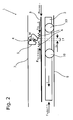
- eine seitliche, schematische Ansicht der erfindungsgemäßen Ein-/Ausstiegsvorrichtung, wobei der Auszug 2 gebremst bzw. blockiert ist.
- Die erfindungsgemäße Ein-Ausstiegsvorrichtung 1 umfasst einen Ausschub 2, d.h einen linear geführten Schiebetritt. Dieser Ausschub 2 ist an beiden zur Ausschubrichtung parallelen Seiten des Ausschubs 2 über die Rollen 10 in einer angedeuteten Führung 9 geführt, die ihrerseits an einem nicht dargestellten Fahrzeugrahmen befestigt ist. Der Antrieb des Ausschubs 2 erfolgt durch einen nicht dargestellten Motor und ein Zugmitteltrieb, der einen umlaufenden Zahnriemen 3 umfasst. An dem Zahnriemen 3 ist ein Mitnehmer 4 befestigt. Mittels des Mitnehmers 4 wird die Bewegung des Zahnriemens 3 auf den Ausschub 2 übertragen, um diesen zwischen seiner eingefahrenen Stellung und seiner ausgefahrenen Stellung hin- und herzubewegen. Es ist eine Relativbewegung zwischen dem Mitnehmer 4 und dem Ausschub 2 vorgesehen. Diese ist dadurch ermöglicht, dass der Mitnehmer in eine schwenkbeweglich am Auszug 2 gelagerte Nockenscheibe 5 eingreift. Deren Bewegung ist eingeschränkt und gibt dadurch den maximalen Verschiebeweg zwischen Ausschub 2 und Mitnehmer 4 vor. Es sind Federn 6 vorgesehen, um bei Fehlen einer äußeren Krafteinwirkung auf den Ausschub 2, wie es in
Figur 1 gezeigt ist, die Nockenscheibe 5 in ihrer, inFigur 1 gezeigten Mittenstellung zu halten, beziehungsweise eine Rückstellung in diese Stellung zu bewirken. In dieser Mittenstellung der Nockenscheibe 5 bewirkt diese keine Bremswirkung. Bei Einwirken einer äußeren Kraft Faußen, wie es inFigur 2 gezeigt ist, kommt es zu einer Relativbewegung zwischen Mitnehmer 4 und Ausschub 2 um die Strecke 11. Dies bewirkt ein Verschwenken der Nockenscheibe 5, die mit einem ihrer Nocken einen Bremshub 8 zurücklegt und mit einem der äußeren Kraft Faußen entsprechenden Anpressdruck gegen eine Reibfläche 7 des Rahmens gedrückt wird. Es stellt sich eine Bremswirkung ein, die den Ausschub 2 in seiner Ausfahrbewegung bremst oder das Zurückschieben des Auszugs 2 entgegen der Ausfahrrichtung hemmt oder unterbindet. Aufgrund der beidseitigen Verschwenkbarkeit der Nockenscheibe 5 aus der Mittelstellung (gelöste Stellung) in die beiden Bremsstellungen ermöglicht sich auch bei umgekehrter äußerer Krafteinwirkrichtung eine Bremswirkung. Hierzu weist die vorliegende Nockenscheibe 5 zwei Nocken auf.
Claims (11)
- Ein- /Ausstiegsvorrichtung (1) für ein Fahrzeug aufweisend: einen zwischen einer eingefahrenen und ausgefahrenen Stellung hin- und herbeweglichen Ausschub (2), einen angetriebenen Mitnehmer (4), der den Ausschub (2) mitnimmt, einen Motor und ein zugehöriges Getriebe (3), um den Mitnehmer (4) anzutreiben, Bremsmittel (5), um den Ausschub (2) wenigstens zu bremsen, dadurch gekennzeichnet, dass der Ausschub (2) relativ beweglich zu dem Mitnehmer (4) gelagert ist, und durch die Relativbewegung zwischen Ausschub (2) und Mitnehmer (4) die Bremsmittel (5) wenigstens aus ihrer Lösestellung in ihre Bremsstellung bewegt werden.
- Ein-/Ausstiegsvorrichtung (1) gemäß Anspruch 1, dadurch gekennzeichnet, dass die Bremsmittel (5) durch eine Rückstellkraft (6) in ihre Lösestellung bewegt werden.
- Ein-/Ausstiegsvorrichtung (1) gemäß dem vorhergehenden Ansprüche, dadurch gekennzeichnet, dass die Relativbewegung von Ausschub (2) und Mitnehmer (4) so ausgestaltet ist, dass eine mittlere Lösestellung und zwei, den beiden Bewegungsrichtungen der Relativbewegung entsprechende Bremsstellungen vorgesehen sind.
- Ein-/Ausstiegsvorrichtung (1) gemäß einem der vorhergehenden Ansprüche, dadurch gekennzeichnet, dass das Getriebe (3) einen formschlüssigen oder kraftschlüssigen, bevorzugt formschlüssigen, Zugmitteltrieb aufweist.
- Ein-/Ausstiegsvorrichtung (1) gemäß dem vorhergehenden Anspruch, dadurch gekennzeichnet, dass der Mitnehmer (4) an einem Riemen (3) des Zugmitteltriebs befestigt ist.
- Ein-/Ausstiegsvorrichtung (1) gemäß einem der vorhergehenden Ansprüche, dadurch gekennzeichnet, dass die Bremsmittel (5) eine am Ausschub (2) verschwenkbar gelagerte Nockenscheibe umfassen, die mit dem Mitnehmer (4) zur Erzeugung einer Bremskraft zusammenwirkt.
- Ein-/Ausstiegsvorrichtung (1) gemäß einem der vorhergehenden Ansprüche, dadurch gekennzeichnet, dass der Motor ein Elektromotor, ein hydraulischer oder pneumatischer Motor ist.
- Ein-/Ausstiegsvorrichtung (1) gemäß einem der vorhergehenden Ansprüche, dadurch gekennzeichnet, das die Bremsmittel (5) mit einer Reibfläche (7) zusammenwirken.
- Ein-/Ausstiegsvorrichtung (1) gemäß einem der vorhergehenden Ansprüche, dadurch gekennzeichnet, dass der Ausschub (2) linear verschiebbar gelagert ist.
- Ein-/Ausstiegsvorrichtung (1) gemäß einem der vorhergehenden Ansprüche, dadurch gekennzeichnet, dass die Stellung der Bremsmittel (5) mittels eines optischen, magnetischen oder elektromechanischen Sensors detektiert wird.
- Personenbeförderungsfahrzeug gekennzeichnet durch eine Ein-/Ausstiegsvorrichtung (1) gemäß einem der vorhergehenden Ansprüche.
Priority Applications (1)
| Application Number | Priority Date | Filing Date | Title |
|---|---|---|---|
| PL10794941T PL2648959T3 (pl) | 2010-12-08 | 2010-12-08 | Element wysuwany do wsiadania/wysiadania z elementami hamującymi |
Applications Claiming Priority (1)
| Application Number | Priority Date | Filing Date | Title |
|---|---|---|---|
| PCT/EP2010/069190 WO2012076048A1 (de) | 2010-12-08 | 2010-12-08 | Ein-/ausstiegsausschub mit bremsmitteln |
Publications (2)
| Publication Number | Publication Date |
|---|---|
| EP2648959A1 EP2648959A1 (de) | 2013-10-16 |
| EP2648959B1 true EP2648959B1 (de) | 2014-08-06 |
Family
ID=44370641
Family Applications (1)
| Application Number | Title | Priority Date | Filing Date |
|---|---|---|---|
| EP10794941.4A Not-in-force EP2648959B1 (de) | 2010-12-08 | 2010-12-08 | Ein-/ausstiegsausschub mit bremsmitteln |
Country Status (7)
| Country | Link |
|---|---|
| US (1) | US8770607B2 (de) |
| EP (1) | EP2648959B1 (de) |
| KR (1) | KR101501859B1 (de) |
| ES (1) | ES2509266T3 (de) |
| PL (1) | PL2648959T3 (de) |
| RU (1) | RU2550095C2 (de) |
| WO (1) | WO2012076048A1 (de) |
Families Citing this family (2)
| Publication number | Priority date | Publication date | Assignee | Title |
|---|---|---|---|---|
| PL3365216T3 (pl) * | 2015-10-23 | 2020-03-31 | Gebr. Bode Gmbh & Co. Kg | Pneumatyczne czyszczenie płyty stopnia |
| US11572019B2 (en) | 2020-02-10 | 2023-02-07 | Norco Industries, Inc. | Extending and retracting step assembly |
Family Cites Families (9)
| Publication number | Priority date | Publication date | Assignee | Title |
|---|---|---|---|---|
| US4116457A (en) * | 1977-08-31 | 1978-09-26 | Nerem Marvin E | Step assembly for vehicle |
| SU1318455A1 (ru) * | 1985-07-22 | 1987-06-23 | Особое Конструкторское Бюро Пожарных Машин | Убирающа с подножка транспортного средства |
| US5085450A (en) * | 1990-12-13 | 1992-02-04 | The Dometic Corporation | Step stall prevention for vehicle steps |
| US5224722A (en) * | 1990-12-17 | 1993-07-06 | Hogan Mfg., Inc. | Leaf chain drive assembly |
| DE10235871A1 (de) * | 2002-07-31 | 2004-02-12 | Pintsch Bamag Antriebs- Und Verkehrstechnik Gmbh | Schiebetritt |
| US6746033B1 (en) * | 2002-10-31 | 2004-06-08 | Mcdaniel Patrick K. | Motorized vehicle step assembly |
| RU39114U1 (ru) * | 2003-12-10 | 2004-07-20 | Открытое акционерное общество "Днепропетровский завод по ремонту и строительству пассажирских вагонов" | Входная подножка пассажирского вагона |
| DE202006017488U1 (de) | 2006-11-16 | 2008-03-27 | Gebr. Bode Gmbh & Co. Kg | Ein-/Ausstiegsvorrichtung für ein Fahrzeug des öffentlichen Personenverkehrs mit einem in einem Rahmen angeordneten Schiebetritt |
| US7857337B2 (en) * | 2008-01-25 | 2010-12-28 | Actuant Corporation | Motorized collapsible step |
-
2010
- 2010-12-08 KR KR1020137014532A patent/KR101501859B1/ko not_active Expired - Fee Related
- 2010-12-08 US US13/992,516 patent/US8770607B2/en not_active Expired - Fee Related
- 2010-12-08 PL PL10794941T patent/PL2648959T3/pl unknown
- 2010-12-08 RU RU2013130990/11A patent/RU2550095C2/ru not_active IP Right Cessation
- 2010-12-08 ES ES10794941.4T patent/ES2509266T3/es active Active
- 2010-12-08 EP EP10794941.4A patent/EP2648959B1/de not_active Not-in-force
- 2010-12-08 WO PCT/EP2010/069190 patent/WO2012076048A1/de not_active Ceased
Also Published As
| Publication number | Publication date |
|---|---|
| RU2550095C2 (ru) | 2015-05-10 |
| EP2648959A1 (de) | 2013-10-16 |
| RU2013130990A (ru) | 2015-01-20 |
| US20130277938A1 (en) | 2013-10-24 |
| US8770607B2 (en) | 2014-07-08 |
| WO2012076048A1 (de) | 2012-06-14 |
| ES2509266T3 (es) | 2014-10-17 |
| KR20130109178A (ko) | 2013-10-07 |
| PL2648959T3 (pl) | 2014-12-31 |
| KR101501859B1 (ko) | 2015-03-12 |
Similar Documents
| Publication | Publication Date | Title |
|---|---|---|
| EP0806538B1 (de) | Motorisch angetriebener Fensterheber mit elektronischem Einklemmschutz für ein Kraftfahrzeug | |
| EP1905625B1 (de) | Rollo mit hinterschneidungsfreier Führungsschiene | |
| EP2459476B1 (de) | Vorrichtung zur mitnahme einer schachttür durch eine fahrkorbtür | |
| EP1859976B1 (de) | Rollo mit geräuschfreiem Spiralfederantrieb | |
| EP1462601B1 (de) | Sektionaltor | |
| EP0284066B1 (de) | Schnellauftor | |
| DE102013113483B4 (de) | Schiebetüreinrichtung für die seitliche Türöffnung eines Personenkraftfahrzeugs; Personenkraftfahrzeug mit Schiebetüreinrichtung | |
| DE102013110790A1 (de) | Aufzuganlage | |
| EP1999043B1 (de) | Werkstückträgersystem | |
| DE202013100965U1 (de) | Schiebegerät für Schienenfahrzeuge | |
| DE102016007070A1 (de) | Fangvorrichtung für Hubeinrichtung | |
| EP1714813A2 (de) | Rollo mit Einklemmschutz | |
| WO2012076048A1 (de) | Ein-/ausstiegsausschub mit bremsmitteln | |
| DE102015106342A1 (de) | Ein- und Aussteighilfe | |
| EP1566358A1 (de) | Triebwerksraumloser Treibscheibenaufzug | |
| EP3224179B1 (de) | Führungseinrichtung für ein aufzugsystem | |
| DE102017217721A1 (de) | Personenfördervorrichtung mit Laufrollen- und Schonrollenführung der Stufenkette sowie Verfahren zum Führen einer Stufenkette mit Laufrollen und Schonrollen | |
| DE10349904C5 (de) | Sektionaltor | |
| EP1878686B1 (de) | Türkonstruktion für einen Aufzug | |
| EP3081522A1 (de) | Fahrtreppe mit gemeinsamen rücklaufschienen | |
| DE102007030139B4 (de) | Verstellantrieb zur Bewegung eines Funktionselementes in oder an einer Kraftfahrzeugkarosserie | |
| DE10223561B4 (de) | Verfahren und Anordnung zum Aus- und Einschwenken von Förderarmen an Förderwagen | |
| EP1892151B1 (de) | Schiebetritt zum Einbau in ein Fahrzeug des öffentlichen Personenverkehrs mit einer geneigten Fußbodenfläche | |
| DE102018212172A1 (de) | Aufzugsbremsanordnung | |
| DE102019106300B4 (de) | Antriebsvorrichtung für den Antrieb einer Rollovorrichtung eines rahmenlosen Fahrzeugfensters |
Legal Events
| Date | Code | Title | Description |
|---|---|---|---|
| PUAI | Public reference made under article 153(3) epc to a published international application that has entered the european phase |
Free format text: ORIGINAL CODE: 0009012 |
|
| 17P | Request for examination filed |
Effective date: 20130523 |
|
| AK | Designated contracting states |
Kind code of ref document: A1 Designated state(s): AL AT BE BG CH CY CZ DE DK EE ES FI FR GB GR HR HU IE IS IT LI LT LU LV MC MK MT NL NO PL PT RO RS SE SI SK SM TR |
|
| DAX | Request for extension of the european patent (deleted) | ||
| GRAP | Despatch of communication of intention to grant a patent |
Free format text: ORIGINAL CODE: EPIDOSNIGR1 |
|
| INTG | Intention to grant announced |
Effective date: 20140328 |
|
| GRAS | Grant fee paid |
Free format text: ORIGINAL CODE: EPIDOSNIGR3 |
|
| GRAA | (expected) grant |
Free format text: ORIGINAL CODE: 0009210 |
|
| AK | Designated contracting states |
Kind code of ref document: B1 Designated state(s): AL AT BE BG CH CY CZ DE DK EE ES FI FR GB GR HR HU IE IS IT LI LT LU LV MC MK MT NL NO PL PT RO RS SE SI SK SM TR |
|
| REG | Reference to a national code |
Ref country code: GB Ref legal event code: FG4D Free format text: NOT ENGLISH |
|
| REG | Reference to a national code |
Ref country code: CH Ref legal event code: EP Ref country code: AT Ref legal event code: REF Ref document number: 680875 Country of ref document: AT Kind code of ref document: T Effective date: 20140815 |
|
| REG | Reference to a national code |
Ref country code: IE Ref legal event code: FG4D Free format text: LANGUAGE OF EP DOCUMENT: GERMAN |
|
| REG | Reference to a national code |
Ref country code: DE Ref legal event code: R096 Ref document number: 502010007621 Country of ref document: DE Effective date: 20140918 |
|
| REG | Reference to a national code |
Ref country code: ES Ref legal event code: FG2A Ref document number: 2509266 Country of ref document: ES Kind code of ref document: T3 Effective date: 20141017 |
|
| REG | Reference to a national code |
Ref country code: NL Ref legal event code: T3 |
|
| REG | Reference to a national code |
Ref country code: PL Ref legal event code: T3 |
|
| REG | Reference to a national code |
Ref country code: LT Ref legal event code: MG4D |
|
| PG25 | Lapsed in a contracting state [announced via postgrant information from national office to epo] |
Ref country code: GR Free format text: LAPSE BECAUSE OF FAILURE TO SUBMIT A TRANSLATION OF THE DESCRIPTION OR TO PAY THE FEE WITHIN THE PRESCRIBED TIME-LIMIT Effective date: 20141107 Ref country code: LT Free format text: LAPSE BECAUSE OF FAILURE TO SUBMIT A TRANSLATION OF THE DESCRIPTION OR TO PAY THE FEE WITHIN THE PRESCRIBED TIME-LIMIT Effective date: 20140806 Ref country code: SE Free format text: LAPSE BECAUSE OF FAILURE TO SUBMIT A TRANSLATION OF THE DESCRIPTION OR TO PAY THE FEE WITHIN THE PRESCRIBED TIME-LIMIT Effective date: 20140806 Ref country code: BG Free format text: LAPSE BECAUSE OF FAILURE TO SUBMIT A TRANSLATION OF THE DESCRIPTION OR TO PAY THE FEE WITHIN THE PRESCRIBED TIME-LIMIT Effective date: 20141106 Ref country code: FI Free format text: LAPSE BECAUSE OF FAILURE TO SUBMIT A TRANSLATION OF THE DESCRIPTION OR TO PAY THE FEE WITHIN THE PRESCRIBED TIME-LIMIT Effective date: 20140806 Ref country code: PT Free format text: LAPSE BECAUSE OF FAILURE TO SUBMIT A TRANSLATION OF THE DESCRIPTION OR TO PAY THE FEE WITHIN THE PRESCRIBED TIME-LIMIT Effective date: 20141209 Ref country code: NO Free format text: LAPSE BECAUSE OF FAILURE TO SUBMIT A TRANSLATION OF THE DESCRIPTION OR TO PAY THE FEE WITHIN THE PRESCRIBED TIME-LIMIT Effective date: 20141106 |
|
| PG25 | Lapsed in a contracting state [announced via postgrant information from national office to epo] |
Ref country code: CY Free format text: LAPSE BECAUSE OF FAILURE TO SUBMIT A TRANSLATION OF THE DESCRIPTION OR TO PAY THE FEE WITHIN THE PRESCRIBED TIME-LIMIT Effective date: 20140806 Ref country code: IS Free format text: LAPSE BECAUSE OF FAILURE TO SUBMIT A TRANSLATION OF THE DESCRIPTION OR TO PAY THE FEE WITHIN THE PRESCRIBED TIME-LIMIT Effective date: 20141206 Ref country code: HR Free format text: LAPSE BECAUSE OF FAILURE TO SUBMIT A TRANSLATION OF THE DESCRIPTION OR TO PAY THE FEE WITHIN THE PRESCRIBED TIME-LIMIT Effective date: 20140806 Ref country code: RS Free format text: LAPSE BECAUSE OF FAILURE TO SUBMIT A TRANSLATION OF THE DESCRIPTION OR TO PAY THE FEE WITHIN THE PRESCRIBED TIME-LIMIT Effective date: 20140806 Ref country code: LV Free format text: LAPSE BECAUSE OF FAILURE TO SUBMIT A TRANSLATION OF THE DESCRIPTION OR TO PAY THE FEE WITHIN THE PRESCRIBED TIME-LIMIT Effective date: 20140806 |
|
| PG25 | Lapsed in a contracting state [announced via postgrant information from national office to epo] |
Ref country code: DK Free format text: LAPSE BECAUSE OF FAILURE TO SUBMIT A TRANSLATION OF THE DESCRIPTION OR TO PAY THE FEE WITHIN THE PRESCRIBED TIME-LIMIT Effective date: 20140806 Ref country code: SK Free format text: LAPSE BECAUSE OF FAILURE TO SUBMIT A TRANSLATION OF THE DESCRIPTION OR TO PAY THE FEE WITHIN THE PRESCRIBED TIME-LIMIT Effective date: 20140806 Ref country code: RO Free format text: LAPSE BECAUSE OF FAILURE TO SUBMIT A TRANSLATION OF THE DESCRIPTION OR TO PAY THE FEE WITHIN THE PRESCRIBED TIME-LIMIT Effective date: 20140806 Ref country code: EE Free format text: LAPSE BECAUSE OF FAILURE TO SUBMIT A TRANSLATION OF THE DESCRIPTION OR TO PAY THE FEE WITHIN THE PRESCRIBED TIME-LIMIT Effective date: 20140806 |
|
| REG | Reference to a national code |
Ref country code: DE Ref legal event code: R097 Ref document number: 502010007621 Country of ref document: DE |
|
| PLBE | No opposition filed within time limit |
Free format text: ORIGINAL CODE: 0009261 |
|
| STAA | Information on the status of an ep patent application or granted ep patent |
Free format text: STATUS: NO OPPOSITION FILED WITHIN TIME LIMIT |
|
| PG25 | Lapsed in a contracting state [announced via postgrant information from national office to epo] |
Ref country code: BE Free format text: LAPSE BECAUSE OF NON-PAYMENT OF DUE FEES Effective date: 20141231 |
|
| 26N | No opposition filed |
Effective date: 20150507 |
|
| PG25 | Lapsed in a contracting state [announced via postgrant information from national office to epo] |
Ref country code: LU Free format text: LAPSE BECAUSE OF FAILURE TO SUBMIT A TRANSLATION OF THE DESCRIPTION OR TO PAY THE FEE WITHIN THE PRESCRIBED TIME-LIMIT Effective date: 20141208 |
|
| REG | Reference to a national code |
Ref country code: IE Ref legal event code: MM4A |
|
| PG25 | Lapsed in a contracting state [announced via postgrant information from national office to epo] |
Ref country code: IE Free format text: LAPSE BECAUSE OF NON-PAYMENT OF DUE FEES Effective date: 20141208 |
|
| PG25 | Lapsed in a contracting state [announced via postgrant information from national office to epo] |
Ref country code: SI Free format text: LAPSE BECAUSE OF FAILURE TO SUBMIT A TRANSLATION OF THE DESCRIPTION OR TO PAY THE FEE WITHIN THE PRESCRIBED TIME-LIMIT Effective date: 20140806 |
|
| REG | Reference to a national code |
Ref country code: FR Ref legal event code: PLFP Year of fee payment: 6 |
|
| PG25 | Lapsed in a contracting state [announced via postgrant information from national office to epo] |
Ref country code: SM Free format text: LAPSE BECAUSE OF FAILURE TO SUBMIT A TRANSLATION OF THE DESCRIPTION OR TO PAY THE FEE WITHIN THE PRESCRIBED TIME-LIMIT Effective date: 20140806 |
|
| PG25 | Lapsed in a contracting state [announced via postgrant information from national office to epo] |
Ref country code: MC Free format text: LAPSE BECAUSE OF FAILURE TO SUBMIT A TRANSLATION OF THE DESCRIPTION OR TO PAY THE FEE WITHIN THE PRESCRIBED TIME-LIMIT Effective date: 20140806 |
|
| PG25 | Lapsed in a contracting state [announced via postgrant information from national office to epo] |
Ref country code: HU Free format text: LAPSE BECAUSE OF FAILURE TO SUBMIT A TRANSLATION OF THE DESCRIPTION OR TO PAY THE FEE WITHIN THE PRESCRIBED TIME-LIMIT; INVALID AB INITIO Effective date: 20101208 Ref country code: MT Free format text: LAPSE BECAUSE OF FAILURE TO SUBMIT A TRANSLATION OF THE DESCRIPTION OR TO PAY THE FEE WITHIN THE PRESCRIBED TIME-LIMIT Effective date: 20140806 |
|
| REG | Reference to a national code |
Ref country code: FR Ref legal event code: PLFP Year of fee payment: 7 |
|
| REG | Reference to a national code |
Ref country code: FR Ref legal event code: PLFP Year of fee payment: 8 |
|
| PGFP | Annual fee paid to national office [announced via postgrant information from national office to epo] |
Ref country code: CZ Payment date: 20171130 Year of fee payment: 8 Ref country code: FR Payment date: 20171219 Year of fee payment: 8 Ref country code: NL Payment date: 20171219 Year of fee payment: 8 Ref country code: TR Payment date: 20171207 Year of fee payment: 8 |
|
| PGFP | Annual fee paid to national office [announced via postgrant information from national office to epo] |
Ref country code: CH Payment date: 20171221 Year of fee payment: 8 Ref country code: PL Payment date: 20171128 Year of fee payment: 8 Ref country code: GB Payment date: 20171221 Year of fee payment: 8 Ref country code: IT Payment date: 20171218 Year of fee payment: 8 Ref country code: AT Payment date: 20171215 Year of fee payment: 8 |
|
| PGFP | Annual fee paid to national office [announced via postgrant information from national office to epo] |
Ref country code: ES Payment date: 20180105 Year of fee payment: 8 Ref country code: DE Payment date: 20171219 Year of fee payment: 8 |
|
| PG25 | Lapsed in a contracting state [announced via postgrant information from national office to epo] |
Ref country code: MK Free format text: LAPSE BECAUSE OF FAILURE TO SUBMIT A TRANSLATION OF THE DESCRIPTION OR TO PAY THE FEE WITHIN THE PRESCRIBED TIME-LIMIT Effective date: 20140806 |
|
| PG25 | Lapsed in a contracting state [announced via postgrant information from national office to epo] |
Ref country code: AL Free format text: LAPSE BECAUSE OF FAILURE TO SUBMIT A TRANSLATION OF THE DESCRIPTION OR TO PAY THE FEE WITHIN THE PRESCRIBED TIME-LIMIT Effective date: 20140806 |
|
| REG | Reference to a national code |
Ref country code: DE Ref legal event code: R119 Ref document number: 502010007621 Country of ref document: DE |
|
| PG25 | Lapsed in a contracting state [announced via postgrant information from national office to epo] |
Ref country code: CZ Free format text: LAPSE BECAUSE OF NON-PAYMENT OF DUE FEES Effective date: 20181208 |
|
| REG | Reference to a national code |
Ref country code: CH Ref legal event code: PL |
|
| REG | Reference to a national code |
Ref country code: NL Ref legal event code: MM Effective date: 20190101 |
|
| REG | Reference to a national code |
Ref country code: AT Ref legal event code: MM01 Ref document number: 680875 Country of ref document: AT Kind code of ref document: T Effective date: 20181208 |
|
| GBPC | Gb: european patent ceased through non-payment of renewal fee |
Effective date: 20181208 |
|
| PG25 | Lapsed in a contracting state [announced via postgrant information from national office to epo] |
Ref country code: NL Free format text: LAPSE BECAUSE OF NON-PAYMENT OF DUE FEES Effective date: 20190101 |
|
| PG25 | Lapsed in a contracting state [announced via postgrant information from national office to epo] |
Ref country code: DE Free format text: LAPSE BECAUSE OF NON-PAYMENT OF DUE FEES Effective date: 20190702 Ref country code: IT Free format text: LAPSE BECAUSE OF NON-PAYMENT OF DUE FEES Effective date: 20181208 Ref country code: FR Free format text: LAPSE BECAUSE OF NON-PAYMENT OF DUE FEES Effective date: 20181231 |
|
| PG25 | Lapsed in a contracting state [announced via postgrant information from national office to epo] |
Ref country code: AT Free format text: LAPSE BECAUSE OF NON-PAYMENT OF DUE FEES Effective date: 20181208 Ref country code: GB Free format text: LAPSE BECAUSE OF NON-PAYMENT OF DUE FEES Effective date: 20181208 Ref country code: LI Free format text: LAPSE BECAUSE OF NON-PAYMENT OF DUE FEES Effective date: 20181231 Ref country code: CH Free format text: LAPSE BECAUSE OF NON-PAYMENT OF DUE FEES Effective date: 20181231 |
|
| REG | Reference to a national code |
Ref country code: ES Ref legal event code: FD2A Effective date: 20200131 |
|
| PG25 | Lapsed in a contracting state [announced via postgrant information from national office to epo] |
Ref country code: ES Free format text: LAPSE BECAUSE OF NON-PAYMENT OF DUE FEES Effective date: 20181209 |
|
| PG25 | Lapsed in a contracting state [announced via postgrant information from national office to epo] |
Ref country code: PL Free format text: LAPSE BECAUSE OF NON-PAYMENT OF DUE FEES Effective date: 20181208 |
|
| PG25 | Lapsed in a contracting state [announced via postgrant information from national office to epo] |
Ref country code: TR Free format text: LAPSE BECAUSE OF NON-PAYMENT OF DUE FEES Effective date: 20181208 |