EP2648951B1 - Bremssystem und verfahren zum bremsen eines fahrzeuges bei sprunghaften veränderungen des reibungskoeffizienten - Google Patents
Bremssystem und verfahren zum bremsen eines fahrzeuges bei sprunghaften veränderungen des reibungskoeffizienten Download PDFInfo
- Publication number
- EP2648951B1 EP2648951B1 EP11771121.8A EP11771121A EP2648951B1 EP 2648951 B1 EP2648951 B1 EP 2648951B1 EP 11771121 A EP11771121 A EP 11771121A EP 2648951 B1 EP2648951 B1 EP 2648951B1
- Authority
- EP
- European Patent Office
- Prior art keywords
- brake
- friction
- coefficient
- braking
- wheel
- Prior art date
- Legal status (The legal status is an assumption and is not a legal conclusion. Google has not performed a legal analysis and makes no representation as to the accuracy of the status listed.)
- Not-in-force
Links
Images

Classifications
-
- B—PERFORMING OPERATIONS; TRANSPORTING
- B60—VEHICLES IN GENERAL
- B60T—VEHICLE BRAKE CONTROL SYSTEMS OR PARTS THEREOF; BRAKE CONTROL SYSTEMS OR PARTS THEREOF, IN GENERAL; ARRANGEMENT OF BRAKING ELEMENTS ON VEHICLES IN GENERAL; PORTABLE DEVICES FOR PREVENTING UNWANTED MOVEMENT OF VEHICLES; VEHICLE MODIFICATIONS TO FACILITATE COOLING OF BRAKES
- B60T8/00—Arrangements for adjusting wheel-braking force to meet varying vehicular or ground-surface conditions, e.g. limiting or varying distribution of braking force
- B60T8/17—Using electrical or electronic regulation means to control braking
- B60T8/176—Brake regulation specially adapted to prevent excessive wheel slip during vehicle deceleration, e.g. ABS
- B60T8/1763—Brake regulation specially adapted to prevent excessive wheel slip during vehicle deceleration, e.g. ABS responsive to the coefficient of friction between the wheels and the ground surface
-
- B—PERFORMING OPERATIONS; TRANSPORTING
- B60—VEHICLES IN GENERAL
- B60T—VEHICLE BRAKE CONTROL SYSTEMS OR PARTS THEREOF; BRAKE CONTROL SYSTEMS OR PARTS THEREOF, IN GENERAL; ARRANGEMENT OF BRAKING ELEMENTS ON VEHICLES IN GENERAL; PORTABLE DEVICES FOR PREVENTING UNWANTED MOVEMENT OF VEHICLES; VEHICLE MODIFICATIONS TO FACILITATE COOLING OF BRAKES
- B60T8/00—Arrangements for adjusting wheel-braking force to meet varying vehicular or ground-surface conditions, e.g. limiting or varying distribution of braking force
- B60T8/17—Using electrical or electronic regulation means to control braking
- B60T8/172—Determining control parameters used in the regulation, e.g. by calculations involving measured or detected parameters
-
- B—PERFORMING OPERATIONS; TRANSPORTING
- B60—VEHICLES IN GENERAL
- B60T—VEHICLE BRAKE CONTROL SYSTEMS OR PARTS THEREOF; BRAKE CONTROL SYSTEMS OR PARTS THEREOF, IN GENERAL; ARRANGEMENT OF BRAKING ELEMENTS ON VEHICLES IN GENERAL; PORTABLE DEVICES FOR PREVENTING UNWANTED MOVEMENT OF VEHICLES; VEHICLE MODIFICATIONS TO FACILITATE COOLING OF BRAKES
- B60T13/00—Transmitting braking action from initiating means to ultimate brake actuator with power assistance or drive; Brake systems incorporating such transmitting means, e.g. air-pressure brake systems
- B60T13/10—Transmitting braking action from initiating means to ultimate brake actuator with power assistance or drive; Brake systems incorporating such transmitting means, e.g. air-pressure brake systems with fluid assistance, drive, or release
- B60T13/12—Transmitting braking action from initiating means to ultimate brake actuator with power assistance or drive; Brake systems incorporating such transmitting means, e.g. air-pressure brake systems with fluid assistance, drive, or release the fluid being liquid
- B60T13/14—Transmitting braking action from initiating means to ultimate brake actuator with power assistance or drive; Brake systems incorporating such transmitting means, e.g. air-pressure brake systems with fluid assistance, drive, or release the fluid being liquid using accumulators or reservoirs fed by pumps
- B60T13/142—Systems with master cylinder
- B60T13/145—Master cylinder integrated or hydraulically coupled with booster
- B60T13/146—Part of the system directly actuated by booster pressure
-
- B—PERFORMING OPERATIONS; TRANSPORTING
- B60—VEHICLES IN GENERAL
- B60T—VEHICLE BRAKE CONTROL SYSTEMS OR PARTS THEREOF; BRAKE CONTROL SYSTEMS OR PARTS THEREOF, IN GENERAL; ARRANGEMENT OF BRAKING ELEMENTS ON VEHICLES IN GENERAL; PORTABLE DEVICES FOR PREVENTING UNWANTED MOVEMENT OF VEHICLES; VEHICLE MODIFICATIONS TO FACILITATE COOLING OF BRAKES
- B60T13/00—Transmitting braking action from initiating means to ultimate brake actuator with power assistance or drive; Brake systems incorporating such transmitting means, e.g. air-pressure brake systems
- B60T13/10—Transmitting braking action from initiating means to ultimate brake actuator with power assistance or drive; Brake systems incorporating such transmitting means, e.g. air-pressure brake systems with fluid assistance, drive, or release
- B60T13/66—Electrical control in fluid-pressure brake systems
- B60T13/68—Electrical control in fluid-pressure brake systems by electrically-controlled valves
- B60T13/686—Electrical control in fluid-pressure brake systems by electrically-controlled valves in hydraulic systems or parts thereof
-
- B—PERFORMING OPERATIONS; TRANSPORTING
- B60—VEHICLES IN GENERAL
- B60T—VEHICLE BRAKE CONTROL SYSTEMS OR PARTS THEREOF; BRAKE CONTROL SYSTEMS OR PARTS THEREOF, IN GENERAL; ARRANGEMENT OF BRAKING ELEMENTS ON VEHICLES IN GENERAL; PORTABLE DEVICES FOR PREVENTING UNWANTED MOVEMENT OF VEHICLES; VEHICLE MODIFICATIONS TO FACILITATE COOLING OF BRAKES
- B60T13/00—Transmitting braking action from initiating means to ultimate brake actuator with power assistance or drive; Brake systems incorporating such transmitting means, e.g. air-pressure brake systems
- B60T13/10—Transmitting braking action from initiating means to ultimate brake actuator with power assistance or drive; Brake systems incorporating such transmitting means, e.g. air-pressure brake systems with fluid assistance, drive, or release
- B60T13/66—Electrical control in fluid-pressure brake systems
- B60T13/72—Electrical control in fluid-pressure brake systems in vacuum systems or vacuum booster units
-
- B—PERFORMING OPERATIONS; TRANSPORTING
- B60—VEHICLES IN GENERAL
- B60T—VEHICLE BRAKE CONTROL SYSTEMS OR PARTS THEREOF; BRAKE CONTROL SYSTEMS OR PARTS THEREOF, IN GENERAL; ARRANGEMENT OF BRAKING ELEMENTS ON VEHICLES IN GENERAL; PORTABLE DEVICES FOR PREVENTING UNWANTED MOVEMENT OF VEHICLES; VEHICLE MODIFICATIONS TO FACILITATE COOLING OF BRAKES
- B60T8/00—Arrangements for adjusting wheel-braking force to meet varying vehicular or ground-surface conditions, e.g. limiting or varying distribution of braking force
- B60T8/32—Arrangements for adjusting wheel-braking force to meet varying vehicular or ground-surface conditions, e.g. limiting or varying distribution of braking force responsive to a speed condition, e.g. acceleration or deceleration
- B60T8/321—Arrangements for adjusting wheel-braking force to meet varying vehicular or ground-surface conditions, e.g. limiting or varying distribution of braking force responsive to a speed condition, e.g. acceleration or deceleration deceleration
- B60T8/3255—Systems in which the braking action is dependent on brake pedal data
- B60T8/326—Hydraulic systems
- B60T8/3265—Hydraulic systems with control of the booster
-
- B—PERFORMING OPERATIONS; TRANSPORTING
- B60—VEHICLES IN GENERAL
- B60T—VEHICLE BRAKE CONTROL SYSTEMS OR PARTS THEREOF; BRAKE CONTROL SYSTEMS OR PARTS THEREOF, IN GENERAL; ARRANGEMENT OF BRAKING ELEMENTS ON VEHICLES IN GENERAL; PORTABLE DEVICES FOR PREVENTING UNWANTED MOVEMENT OF VEHICLES; VEHICLE MODIFICATIONS TO FACILITATE COOLING OF BRAKES
- B60T8/00—Arrangements for adjusting wheel-braking force to meet varying vehicular or ground-surface conditions, e.g. limiting or varying distribution of braking force
- B60T8/32—Arrangements for adjusting wheel-braking force to meet varying vehicular or ground-surface conditions, e.g. limiting or varying distribution of braking force responsive to a speed condition, e.g. acceleration or deceleration
- B60T8/34—Arrangements for adjusting wheel-braking force to meet varying vehicular or ground-surface conditions, e.g. limiting or varying distribution of braking force responsive to a speed condition, e.g. acceleration or deceleration having a fluid pressure regulator responsive to a speed condition
- B60T8/42—Arrangements for adjusting wheel-braking force to meet varying vehicular or ground-surface conditions, e.g. limiting or varying distribution of braking force responsive to a speed condition, e.g. acceleration or deceleration having a fluid pressure regulator responsive to a speed condition having expanding chambers for controlling pressure, i.e. closed systems
- B60T8/4275—Pump-back systems
-
- B—PERFORMING OPERATIONS; TRANSPORTING
- B60—VEHICLES IN GENERAL
- B60T—VEHICLE BRAKE CONTROL SYSTEMS OR PARTS THEREOF; BRAKE CONTROL SYSTEMS OR PARTS THEREOF, IN GENERAL; ARRANGEMENT OF BRAKING ELEMENTS ON VEHICLES IN GENERAL; PORTABLE DEVICES FOR PREVENTING UNWANTED MOVEMENT OF VEHICLES; VEHICLE MODIFICATIONS TO FACILITATE COOLING OF BRAKES
- B60T8/00—Arrangements for adjusting wheel-braking force to meet varying vehicular or ground-surface conditions, e.g. limiting or varying distribution of braking force
- B60T8/32—Arrangements for adjusting wheel-braking force to meet varying vehicular or ground-surface conditions, e.g. limiting or varying distribution of braking force responsive to a speed condition, e.g. acceleration or deceleration
- B60T8/34—Arrangements for adjusting wheel-braking force to meet varying vehicular or ground-surface conditions, e.g. limiting or varying distribution of braking force responsive to a speed condition, e.g. acceleration or deceleration having a fluid pressure regulator responsive to a speed condition
- B60T8/44—Arrangements for adjusting wheel-braking force to meet varying vehicular or ground-surface conditions, e.g. limiting or varying distribution of braking force responsive to a speed condition, e.g. acceleration or deceleration having a fluid pressure regulator responsive to a speed condition co-operating with a power-assist booster means associated with a master cylinder for controlling the release and reapplication of brake pressure through an interaction with the power assist device, i.e. open systems
- B60T8/447—Reducing the boost of the power-assist booster means to reduce brake pressure
- B60T8/448—Reducing the boost of the power-assist booster means to reduce brake pressure the power-assist booster means being a vacuum or compressed air booster
-
- B—PERFORMING OPERATIONS; TRANSPORTING
- B60—VEHICLES IN GENERAL
- B60T—VEHICLE BRAKE CONTROL SYSTEMS OR PARTS THEREOF; BRAKE CONTROL SYSTEMS OR PARTS THEREOF, IN GENERAL; ARRANGEMENT OF BRAKING ELEMENTS ON VEHICLES IN GENERAL; PORTABLE DEVICES FOR PREVENTING UNWANTED MOVEMENT OF VEHICLES; VEHICLE MODIFICATIONS TO FACILITATE COOLING OF BRAKES
- B60T2210/00—Detection or estimation of road or environment conditions; Detection or estimation of road shapes
- B60T2210/10—Detection or estimation of road conditions
- B60T2210/12—Friction
- B60T2210/124—Roads with different friction levels
Definitions
- the invention relates to a brake system for vehicles with improved braking properties in driving situations in which the vehicle brakes on a roadway with a negative friction coefficient jump, and a method for braking a vehicle in a corresponding driving situation.
- the publication DE 196 10 863 A1 discloses a method for determining a signal representing the coefficient of friction of the roadway in a brake system, in which a pump controlled by a drive signal is provided for reducing the brake pressure in a wheel brake unit.
- the signal representing the coefficient of friction of the roadway is determined as a function of the detected delivery volume of the delivery pump that occurs in response to a pressure reduction.
- the volume that must be removed from a wheel brake unit for blocking prevention represents a good measure of the coefficient of friction of the road surface on which the respective wheel is moving.
- the control of the feed pump is clocked, generally pulse width modulated.
- the return pump works in an ABS control against the brake pressure generated at the master cylinder, a reduction in the brake booster leads to a lower master cylinder pressure and thus to a lower load on the return pump.
- the return pump thus has a relatively higher flow rate and can promote correspondingly more hydraulic fluid from the wheel brakes back in the direction of the master cylinder. This in turn can be shortened the wheel stops for an ABS control.
- a braking device accordingly comprises means for automatically setting a lower gain of the brake booster when the vehicle is performing an ABS controlled braking maneuver on a negative coefficient of friction road.
- the gain of the brake booster can be influenced in the case of a vacuum brake booster, for example by means of the vacuum pump.
- the aforementioned means for adjusting the gain of the brake booster can thus comprise, for example, a vacuum pump and a control unit, by means of which the vacuum pump is driven in the desired manner.
- the vacuum pump In a brake application to a high coefficient of friction of the master cylinder and thus also the brake booster make a relatively large stroke. As a result, the vacuum level is lowered in the vacuum chamber of the brake booster and the absolute pressure increases, which in turn reduces the gain of the brake booster. In conventional brake systems in this case, the vacuum pump would start to compensate for this effect. According to the invention it is now proposed to reduce the power of the vacuum pump comparatively. For this purpose, z. B. the startup of the vacuum pump can be suppressed, or the vacuum pump can start with a time delay. As a result, the gain of the brake booster is lower compared to a braking maneuver on a roadway with approximately the same coefficient of friction. In braking situations on a roadway with a negative coefficient of friction, the brake pressure generated by the master brake cylinder is thus comparatively lower than in braking situations on a roadway without a negative coefficient of friction jump.
- a suitable sensor system For detecting a negative coefficient of friction jump, i. A transition from a road area with a higher coefficient of friction (eg asphalt) to a road area with a lower coefficient of friction (eg ice), a suitable sensor system is preferably provided.
- the sensor system preferably comprises at least one wheel speed sensor. Another, such as As an optical sensor, is equally applicable.
- a negative coefficient of friction of the road can be detected for example by monitoring the wheel speeds. As soon as the vehicle comes from a road section with a high coefficient of friction on a road section with a significantly lower coefficient of friction and brakes, get the front wheels in slippage, while the rear wheels have significantly less slippage. A negative friction coefficient jump can thus be detected, for example, if the wheel slip of the front wheels exceeds a predetermined first threshold value and the wheel slip of the rear wheels is smaller than a predetermined second threshold value.
- the vacuum level in the vacuum chamber of the brake booster becomes sensory monitored and operated the vacuum pump depending on the vacuum level.
- the vacuum pump during an ABS control as mentioned above, for example, not start or delayed.
- the vacuum pump can be operated, for example, with a slightly lower power than in an ABS braking on a road with approximately constant coefficient of friction.
- FIG. 1 shows a typical brake circuit of a hydraulic brake system with ABS function. This contains a master cylinder 1 with a container arranged thereon for the hydraulic fluid. A brake booster 2 is coupled to a brake pedal 3 and amplifies the braking force applied by the driver.
- the brake pressure generated at the master cylinder 1 is passed via an inlet valve 7 to a wheel brake 4.
- An outlet valve 8 arranged at the outlet of the wheel brake 4 is closed in this state.
- FIG. 2 shows a vehicle 11, which runs at a speed v on a roadway with different coefficients of friction.
- the roadway has a region 12 with a relatively high coefficient of friction ⁇ , such. B, asphalt, and a region 13 with a relatively low coefficient of friction ⁇ , such as snow or ice on.
- the vehicle 11 is in a braking process which has started at location s 0 .
- the vehicle 11 In the illustrated position, the vehicle 11 is located with the front wheels 14 directly at the transition between the region 12 with the high coefficient of friction and the region 13 with the low coefficient of friction.
- the transition between the two regions 12, 13 is also referred to as negative friction coefficient jump.
- the ABS controller becomes active. As a result, the inlet valve 7 is closed and the outlet valve 8 is opened. The hydraulic fluid in the wheel brake 4 thus flows out of the wheel brake 4 into a storage chamber 9 (see FIG Fig. 1 ) and is conveyed from there by means of a so-called return pump 6 in the direction of the master cylinder 1 back. To damp the system, a buffer 5 is provided at the output of the return pump 6.
- the vacuum pump 10 is not activated during braking maneuvers on a roadway with negative Reibwertsprung or only with a time delay.
- it could also be operated with a comparatively lower power.
- the hydraulic brake pressure generated at the master cylinder 1 decreases. This has the consequence that the return pump 6, which must work against the master cylinder pressure is less heavily loaded and thus runs faster.
- the brake pressure at the wheel brake 4 can be reduced faster, so that the wheel starts faster again. The vehicle is thus steered faster again.
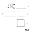
- FIG. 3 again shows the individual process steps of a method for operating a vehicle brake system during a braking maneuver on a roadway with a negative coefficient of friction.
- a driving situation is detected by an algorithm 16, which evaluates the wheel speeds n wheel of the individual wheels 14, 15 and the brake pressure p HZ .
- Said variables n wheel and p Hz are measured by means of corresponding sensors 19 and 20.
- a braking maneuver is detected on a roadway with a negative coefficient of friction.
- a signal is sent to a control unit 18 of the vacuum pump 10.
- the control unit 18 controls the vacuum pump 10 as a function of the vacuum level in the brake booster 2, which is measured by an associated vacuum sensor 17 at.
- the pressure in the vacuum chamber of the brake booster is relatively low - the gain of the brake booster is relatively high in this case - the starting of the vacuum pump 19 is suppressed, for example, and the vacuum pump 10 is not activated. If the pressure is higher - the gain of the brake booster is rather low - can the vacuum pump z. B. also be operated with low power.
Landscapes
- Engineering & Computer Science (AREA)
- Transportation (AREA)
- Mechanical Engineering (AREA)
- Physics & Mathematics (AREA)
- Fluid Mechanics (AREA)
- Regulating Braking Force (AREA)
Description
- Die Erfindung betrifft ein Bremssystem für Fahrzeuge mit verbesserten Bremseigenschaften in Fahrsituationen, in denen das Fahrzeug auf einer Fahrbahn mit einem negativen Reibwertsprung bremst, sowie ein Verfahren zum Bremsen eines Fahrzeuges in einer entsprechenden Fahrsituation.
- Aus dem Stand der Technik sind verschiedene Bremsregelsysteme, wie z. B. ABS, ASR oder ESP, bekannt, mit denen das Blockieren der Räder beim Bremsen verhindert werden kann. Diese Systeme überwachen in der Regel den Radschlupf mittels Rad-Drehzahlsensoren. Erkennt das Bremsregelsystem an einem Rad einen zu hohen Radschlupf, wird der Bremsdruck in der zugehörigen Radbremse vorrübergehend abgebaut. Hierzu wird üblicherweise ein Auslassventil geöffnet. Die in der Radbremse befindliche Bremsflüssigkeit strömt dann durch das Auslassventil in eine Speicherkammer und wird von dort mittels einer Rückförderpumpe in Richtung des Hauptbremszylinders zurück gefördert.
- In bestimmten Bremssituationen, wie z. B. Notbremsungen, in denen ein relativ hoher Bremsdruck an den Radbremsen anliegt, kann es vorkommen, dass die Rückförderpumpe nicht in der Lage ist, die Bremsflüssigkeit ausreichend schnell zurück zu fördern, mit der Folge, dass die Speicherkammer voll läuft. In diesem Fall baut sich der an der Radbremse wirkende Bremsdruck langsamer ab als gewünscht, so dass das zugehörige Rad länger als notwendig blockiert bleibt. In diesem Zustand ist das Fahrzeug bekanntlich nicht lenkbar bzw. wird instabil. Eine Vergrößerung der Speicherkammer oder der Rückförderpumpe wäre prinzipiell möglich, ist aber aus Kostengründen unwirtschaftlich und daher unerwünscht.
- Die Offenlegungsschrift
DE 196 10 863 A1 offenbart ein Verfahren zur Ermittlung eines den Reibwert der Fahrbahn repräsentierenden Signals bei einer Bremsanlage, bei der zum Abbau des Bremsdrucks in einer Radbremseinheit eine durch ein Ansteuersignal gesteuerte Förderpumpe vorgesehen ist. Das den Reibwert der Fahrbahn repräsentierende Signal wird abhängig von dem erfassten, in Reaktion auf einen Druckabbau auftretende Fördervolumen der Förderpumpe ermittelt. Das Volumen, das zur Blockierverhinderung aus einer Radbremseinheit entfernt werden muss, stellt ein gutes Maß für den Reibwert der Fahrbahn dar, auf dem sich das jeweilige Rad bewegt. Die Ansteuerung der Förderpumpe geschieht dabei getaktet, im allgemeinen pulsweitenmoduliert. - Es ist daher die Aufgabe der vorherigen Erfindung, eine Bremsvorrichtung zum Bremsen von Fahrzeugen beziehungsweise ein entsprechendes Verfahren zu schaffen, mit dem die Stillstandszeiten der Räder bei einer ABS-Bremsung verringert werden können, ohne die Speicherkammer oder die Rückförderpumpe größer dimensionieren zu müssen.
- Gelöst wird diese Aufgabe gemäß der Erfindung durch die im Patentanspruch 1 sowie im Patentanspruch 4 angegebenen Merkmale. Weitere Ausgestaltungen der Erfindung sind Gegenstand von Unteransprüchen.
- Gemäß der Erfindung wird vorgeschlagen, in Fahrsituationen, in denen das Fahrzeug ein Bremsmanöver mit ABS-Regelung auf einer Fahrbahn mit einem negativen Reibwertsprung durchführt, die Verstärkung des Bremskraftverstärkers zu reduzieren. Da die Rückförderpumpe bei einer ABS-Regelung gegen den am Hauptbremszylinder erzeugten Bremsdruck arbeitet, führt eine Verringerung der Bremskraftverstärkung zu einem geringeren Hauptbremszylinderdruck und somit zu einer geringeren Belastung für die Rückförderpumpe. Die Rückförderpumpe hat somit eine vergleichsweise höhere Förderleistung und kann entsprechend mehr Hydraulikfluid aus den Radbremsen zurück in Richtung des Hauptbremszylinders fördern. Dadurch können wiederum die Radstillstandszeiten bei einer ABS-Regelung verkürzt werden.
- Eine erfindungsgemäße Bremsvorrichtung umfasst entsprechend Mittel zum automatischen Einstellen einer geringeren Verstärkung des Bremskraftverstärkers, wenn das Fahrzeug ein Bremsmanöver mit ABS-Regelung auf einer Fahrbahn mit negativem Reibwertsprung durchführt.
- Die Verstärkung des Bremskraftverstärkers kann im Falle eines Unterdruck-Bremskraftverstärkers beispielsweise mit Hilfe der Vakuumpumpe beeinflusst werden. Die vorstehend genannten Mittel zum Einstellen der Verstärkung des Bremskraftverstärkers können somit zum Beispiel eine Vakuumpumpe und eine Steuereinheit umfassen, mittels derer die Vakuumpumpe in der gewünschten Weise angesteuert wird.
- Bei einem Bremsmanöver auf hohem Reibwert machen der Hauptbremszylinder und somit auch der Bremskraftverstärker einen relativ großen Hub. Dadurch wird das Unterdruckniveau in der Vakuumkammer des Bremskraftverstärkers abgesenkt und der Absolutdruck erhöht sich, wodurch sich wiederum die Verstärkung des Bremskraftverstärkers verringert. Bei herkömmlichen Bremsanlagen würde in diesem Fall die Vakuumpumpe anlaufen, um diesen Effekt auszugleichen. Gemäß der Erfindung wird nun vorgeschlagen, die Leistung der Vakuumpumpe vergleichsweise zu reduzieren. Zu diesem Zweck kann z. B. das Anlaufen der Vakuumpumpe unterdrückt werden, oder die Vakuumpumpe kann mit zeitlicher Verzögerung anlaufen. Dadurch ist die Verstärkung des Bremskraftverstärkers im Vergleich zu einem Bremsmanöver auf einer Fahrbahn mit etwa gleichbleibendem Reibwert geringer. In Bremssituationen auf einer Fahrbahn mit einem negativen Reibwertsprung ist der vom Hauptbremszylinder erzeugte Bremsdruck somit vergleichsweise geringer als in Bremssituationen auf einer Fahrbahn ohne negativen Reibwertsprung.
- Zur Erkennung eines negativen Reibwertsprungs, d.h. eines Übergangs von einem Fahrbahnbereich mit höherem Reibwert (z. B. Asphalt) auf einen Fahrbahnbereich mit geringerem Reibwert (z. B. Eis), ist vorzugsweise eine geeignete Sensorik vorgesehen. Die Sensorik umfasst vorzugweise wenigstens einen Rad-Drehzahlsensor. Eine andere, wie z. B. eine optische Sensorik, ist gleichermaßen einsetzbar.
- Ein negativer Reibwertsprung der Fahrbahn kann beispielsweise durch eine Überwachung der Rad-Drehzahlen erkannt werden. Sobald das Fahrzeug von einem Fahrbahnabschnitt mit hohem Reibwert auf einen Fahrbahnabschnitt mit deutlich geringerem Reibwert kommt und dabei bremst, geraten die Vorderräder in Schlupft, während die Hinterräder deutlich weniger Schlupf aufweisen. Ein negativer Reibwertsprung kann somit beispielsweise erkannt werden, wenn der Radschlupf der Vorderräder einen vorgegeben ersten Schwellenwert übersteigt und der Radschlupf der Hinterräder kleiner ist als ein vorgegebener zweiter Schwellenwert.
- Gemäß einer speziellen Ausführungsform der Erfindung wird das Unterdruckniveau in der Vakuumkammer des Bremskraftverstärkers sensorisch überwacht und die Vakuumpumpe abhängig vom Unterdruckniveau betrieben. Bei einem sehr niedrigen Absolutdruck kann die Vakuumpumpe während einer ABS-Regelung, wie vorstehend erwähnt, beispielsweise nicht oder verzögert anlaufen. Bei einem etwas höheren Absolutdruck kann die Vakuumpumpe beispielsweise mit einer etwas geringeren Leistung betrieben werden als bei einer ABS-Bremsung auf einer Fahrbahn mit etwa gleich bleibendem Reibwert.
- Die Erfindung wird nachstehend anhand der beigefügten Zeichnungen beispielhaft näher erläutert. Es zeigen:
-
Figur 1 eine schematische Darstellung eines Bremskreislaufs eines hydraulischen Bremssystems; -
Figur 2 eine schematische Darstellung eines Fahrzeuges auf einer Fahrbahn mit einem negativen Reibwertsprung; -
Figur 3 ein Ablaufdiagramm einer möglichen Ausführungsform eines erfindungsgemäßen Verfahrens. -
Figur 1 zeigt einen typischen Bremskreislauf eines hydraulischen Bremssystems mit ABS-Funktion. Dieser enthält ein Hauptbremszylinder 1 mit einem darauf angeordneten Behälter für das Hydraulikfluid. Ein Bremskraftverstärker 2 ist mit einem Bremspedal 3 gekoppelt und verstärkt die vom Fahrer aufgebrachte Bremskraft. - Der am Hauptbremszylinder 1 erzeugte Bremsdruck wird über ein Einlassventil 7 zu einer Radbremse 4 geleitet. Ein am Ausgang der Radbremse 4 angeordnetes Auslassventil 8 ist in diesem Zustand geschlossen.
-
Figur 2 zeigt ein Fahrzeug 11, das mit einer Geschwindigkeit v auf einer Fahrbahn mit unterschiedlichen Reibwerten fährt. Die Fahrbahn weist einen Bereich 12 mit einem relativ hohen Reibwert µ, wie z. B, Asphalt, und einen Bereich 13 mit einem relativ niedrigen Reibwert µ, wie zum Beispiel Schnee oder Eis, auf. Das Fahrzeug 11 befindet sich in einem Bremsvorgang, der am Ort s0 begonnen hat. - In der dargestellten Position befindet sich das Fahrzeug 11 mit den Vorderrädern 14 direkt am Übergang zwischen dem Bereich 12 mit dem hohen Reibwert und dem Bereich 13 mit dem niedrigen Reibwert. Der Übergang zwischen den beiden Bereichen 12, 13 wird auch als negativer Reibwertsprung bezeichnet.
- Sobald die Vorderräder 14 des Fahrzeugs 11 auf den Bereich 13 mit geringem Reibwert gelangen, blockieren sie und zeigen einen entsprechend hohen Radschlupf. Der Radschlupf wird während der Fahrt mittels Rad-Drehzahlsensoren 19 (siehe
Figur 3 ) überwacht. Die Hinterräder 15 befinden sich in der dargestellten Situation noch auf dem Bereich 12 mit höherem Reibwert und zeigen somit einen deutlich geringeren Radschlupf. - Sobald an den Vorderrädern 14 ein erhöhter Radschlupf festgestellt wurde, wird der ABS-Regler aktiv. Dadurch wird das Einlassventil 7 geschlossen und das Auslassventil 8 geöffnet. Das in der Radbremse 4 befindliche Hydraulikfluid fließt somit aus der Radbremse 4 in eine Speicherkammer 9 (siehe
Fig. 1 ) und wird von dort mittels einer sogenannten Rückförderpumpe 6 in Richtung des Hauptbremszylinders 1 zurück gefördert. Zur Dämpfung des Systems ist am Ausgang der Rückförderpumpe 6 ein Pufferspeicher 5 vorgesehen. - In der Anfangsphase des Bremsvorgangs, wenn sich das Fahrzeug 11 noch auf dem Fahrbahnbereich 12 befindet, wird relativ viel Bremsfluid vom Hauptbremszylinder 1 in die Radbremse 4 verschoben, wobei der Bremskraftverstärker 2 einen entsprechend großen Hub ausführt. Dadurch erhöht sich der Druck in der Vakuumkammer des Bremskraftverstärkers 2. Bei einem Bremsmanöver auf einer Fahrbahn mit gleichmäßigem Reibwert würde in diesem Fall eine Vakuumpumpe 10 anlaufen, um diesen Effekt auszugleichen. Gemäß der Erfindung ist nun für den dargestellten Spezialfall einer Bremsung auf einer Fahrbahn mit negativem Reibwertsprung vorgesehen, die Verstärkung des Bremskraftverstärkers 2 im Vergleich zu einem Bremsmanöver auf gleich bleibendem Reibwert zu reduzieren, beziehungsweise die abnehmende Verstärkung des Bremskraftverstärkers nicht auszugleichen.
- Gemäß einer bevorzugten Ausführungsform der Erfindung wird daher die Vakuumpumpe 10 bei Bremsmanövern auf einer Fahrbahn mit negativem Reibwertsprung nicht oder erst mit zeitlicher Verzögerung aktiviert. Wahlweise könnte sie auch mit einer vergleichsweise geringeren Leistung betrieben werden. Dadurch sinkt der am Hauptbremszylinder 1 erzeugte hydraulische Bremsdruck. Dies hat zur Folge, dass die Rückförderpumpe 6, die gegen den Hauptbremszylinderdruck arbeiten muss, weniger stark belastet ist und somit schneller läuft. Dadurch kann der Bremsdruck an der Radbremse 4 schneller abgebaut werden, so dass das Rad schneller wieder anläuft. Das Fahrzeug wird somit schneller wieder lenkbar.
-
Figur 3 zeigt nochmals die einzelnen Verfahrensschritte eines Verfahrens zum Betreiben einer Fahrzeug-Bremsanlage bei einem Bremsmanöver auf einer Fahrbahn mit negativem Reibwertsprung. Eine solche Fahrsituation wird von einem Algorithmus 16 erkannt, der die Rad-Drehzahlen nRad der einzelnen Räder 14, 15 und den Bremsdruck pHZ auswertet. Die genannten Größen nRad und pHz werden mittels entsprechender Sensoren 19 und 20 gemessen. Wenn der am Hauptbremszylinder 1 anliegende Bremsdruck pHZ größer ist als ein vorgegebener Schwellenwert, zum Beispiel 100 bar, sowie der Radschlupf an den Rädern 14 der Vorderachse größer ist als ein erster Schwellenwert, zum Beispiel 20 %, und der Radschlupf an den Rädern 15 der Hinterachse kleiner ist als ein zweiter Schwellenwert, zum Beispiel 5 %, wird ein Bremsmanöver auf einer Fahrbahn mit negativem Reibwertsprung erkannt. In diesem Fall erfolgt ein Signal an eine Steuereinheit 18 der Vakuumpumpe 10. Die Steuereinheit 18 steuert die Vakuumpumpe 10 dann in Abhängigkeit vom Unterdruckniveau im Bremskraftverstärker 2, der von einem zugehörigen Vakuumsensor 17 gemessen wird, an. Wenn der Druck in der Vakuumkammer des Bremskraftverstärkers relativ gering ist- die Verstärkung des Bremskraftverstärkers ist in diesem Fall relativ hoch - wird das Anlaufen der Vakuumpumpe 19 beispielweise unterdrückt und die Vakuumpumpe 10 nicht aktiviert. Ist der Druck dagegen höher - die Verstärkung des Bremskraftverstärkers ist eher gering - kann die Vakuumpumpe z. B. auch mit geringer Leistung betrieben werden.
Claims (8)
- Bremsvorrichtung zum Bremsen der Räder eines Fahrzeugs (11), umfassend wenigstens einen Hauptbremszylinder (1), einen Bremskraftverstärker (2), eine Radbremse (4), eine Rückförderpumpe (6), mit der ein Hydraulikfluid von der Radbremse (4) in Richtung des Hauptbremszylinders (1) zurückgepumpt werden kann, und eine Sensorik (19, 20) zum Erkennen eines negativen Reibwertsprungs der Fahrbahn,
dadurch gekennzeichnet,dass
Mittel (10, 18) vorgesehen sind, mit denen die Verstärkung des Bremskraftverstärkers (2), wenn ein Bremsmanöver auf einer Fahrbahn mit einem negativen Reibwertsprung erkannt wurde, auf einen kleineren Wert eingestellt wird als bei einem Bremsmanöver auf einer Fahrbahn ohne negativen Reibwertsprung. - Bremsvorrichtung nach Anspruch 1,
dadurch gekennzeichnet,
dass die Mittel (10, 18) eine Steuereinheit (18) und eine Vakuumpumpe (10) umfassen. - Bremsvorrichtung nach Anspruch 1 oder 2,
dadurch gekennzeichnet,
dass die Sensorik (19, 20) wenigstens einen Rad-Drehzahlsensor (19) und einen Sensor (20) zum Erkennen eines Bremsvorgangs umfasst. - Verfahren zum Bremsen der Räder eines Fahrzeuges (11), bei dem das Auftreten eines negativen Reibwertsprungs der Fahrbahn überwacht wird,
dadurch gekennzeichnet,
dass die Verstärkung eines Bremskraftverstärkers (2), wenn ein Bremsmanöver auf einer Fahrbahn mit einem negativen Reibwertsprung erkannt wurde, auf einen kleineren Wert eingestellt wird als bei einem Bremsmanöver auf einer Fahrbahn ohne negativen Reibwertsprung. - Verfahren nach Anspruch 4,
dadurch gekennzeichnet,
dass ferner der Bremsdruck (pHZ) oder eine davon abhängige Größe überwacht wird und eine geringere Verstärkung des Bremskraftverstärkers (2) eingestellt wird, wenn der Bremsdruck (pHZ) größer ist als ein vorgegebener Schwellenwert und ein negativer Reibwertsprung erkannt wurde. - Verfahren nach Anspruch 4 oder 5,
dadurch gekennzeichnet,
dass wenigstens eine Rad-Drehzahl (nRad) eines Vorderrades (14) und eine Rad-Drehzahl (nRad) eines Hinterrades (15) überwacht werden, um das Auftreten eines Reibwertsprungs zu erkennen. - Verfahren nach einem der Ansprüche 4 - 6,
dadurch gekennzeichnet,
dass zur Einstellung der geringeren Verstärkung des Bremskraftverstärkers (2), die Vakuumpumpe (10) mit einer geringeren Leistung betrieben oder vorrübergehend deaktiviert wird, so dass sie im Falle einer ABS-Regelung nicht oder zeitlich verzögert anläuft. - Verfahren nach einem der Ansprüche 4 - 7,
dadurch gekennzeichnet,
dass das Unterdruckniveau im Bremskraftverstärker (2) sensorisch überwacht (17) und die Vakuumpumpe (10) abhängig vom gemessenen Unterdruck betrieben wird.
Applications Claiming Priority (2)
| Application Number | Priority Date | Filing Date | Title |
|---|---|---|---|
| DE102010062816A DE102010062816A1 (de) | 2010-12-10 | 2010-12-10 | Bremssystem und Verfahren zum Bremsen eines Fahrzeuges bei sprunghaften Veränderungen des Reibungskoeffizienten |
| PCT/EP2011/068069 WO2012076224A1 (de) | 2010-12-10 | 2011-10-17 | Bremssystem und verfahren zum bremsen eines fahrzeuges bei sprunghaften veränderungen des reibungskoeffizienten |
Publications (2)
| Publication Number | Publication Date |
|---|---|
| EP2648951A1 EP2648951A1 (de) | 2013-10-16 |
| EP2648951B1 true EP2648951B1 (de) | 2014-08-13 |
Family
ID=44992871
Family Applications (1)
| Application Number | Title | Priority Date | Filing Date |
|---|---|---|---|
| EP11771121.8A Not-in-force EP2648951B1 (de) | 2010-12-10 | 2011-10-17 | Bremssystem und verfahren zum bremsen eines fahrzeuges bei sprunghaften veränderungen des reibungskoeffizienten |
Country Status (5)
| Country | Link |
|---|---|
| US (1) | US20130253795A1 (de) |
| EP (1) | EP2648951B1 (de) |
| CN (1) | CN103228508A (de) |
| DE (1) | DE102010062816A1 (de) |
| WO (1) | WO2012076224A1 (de) |
Families Citing this family (8)
| Publication number | Priority date | Publication date | Assignee | Title |
|---|---|---|---|---|
| DE102012215790A1 (de) | 2012-09-06 | 2014-03-06 | Robert Bosch Gmbh | Steuervorrichtung für einen Pumpenmotor mindestens einer Pumpe eines Bremssystems und Verfahren zum Betreiben eines Pumpenmotors mindestens einer Pumpe eines Bremssystems |
| DE102014201822A1 (de) * | 2014-02-03 | 2015-08-06 | Robert Bosch Gmbh | Verfahren zum Betreiben eines Fahrzeugs |
| US9180953B1 (en) | 2014-04-29 | 2015-11-10 | Roger Durand | Airboat braking system |
| CN106476778A (zh) | 2015-09-01 | 2017-03-08 | 福特全球技术公司 | 用于操作具有电动液压行车制动器和机械驻车制动器的机动车辆制动系统的方法 |
| DE102016214639B4 (de) | 2016-08-08 | 2025-12-24 | Ford Global Technologies, Llc | Verfahren zum Betreiben einer Kraftfahrzeugbremsanlage mit einer elektro-hydraulischen Betriebsbremse und einer mechanischen Feststellbremse sowie Kraftfahrzeugbremsanlage |
| DE102016225352B4 (de) | 2016-12-16 | 2018-10-04 | Volkswagen Aktiengesellschaft | Verfahren zum Schätzen eines Reibwerts einer Fahrbahn mittels eines Kraftfahrzeugs sowie Steuervorrichtung und Kraftfahrzeug |
| US11541893B2 (en) | 2017-09-26 | 2023-01-03 | Nira Dynamics Ab | Friction estimation |
| CN112644497B (zh) * | 2020-12-31 | 2022-04-29 | 东风汽车集团有限公司 | 一种基于运行工况的制动颤振抑制方法和装置 |
Family Cites Families (5)
| Publication number | Priority date | Publication date | Assignee | Title |
|---|---|---|---|---|
| US4057301A (en) * | 1976-06-21 | 1977-11-08 | General Motors Corporation | Brake system |
| DE4416833A1 (de) * | 1994-05-16 | 1995-11-23 | Teves Gmbh Alfred | Bremsanlage für Kraftfahrzeuge mit pneumatischem Bremskraftverstärker |
| DE19610863B4 (de) * | 1996-03-20 | 2004-08-12 | Robert Bosch Gmbh | Verfahren und Vorrichtung zur Ermittlung eines Reibwertsignals |
| JP2003011805A (ja) * | 2001-07-02 | 2003-01-15 | Hitachi Unisia Automotive Ltd | アンチスキッド制御装置 |
| JP4935548B2 (ja) * | 2007-07-11 | 2012-05-23 | 株式会社アドヴィックス | 車両の制動制御装置 |
-
2010
- 2010-12-10 DE DE102010062816A patent/DE102010062816A1/de not_active Withdrawn
-
2011
- 2011-10-17 CN CN2011800591364A patent/CN103228508A/zh active Pending
- 2011-10-17 US US13/992,964 patent/US20130253795A1/en not_active Abandoned
- 2011-10-17 WO PCT/EP2011/068069 patent/WO2012076224A1/de not_active Ceased
- 2011-10-17 EP EP11771121.8A patent/EP2648951B1/de not_active Not-in-force
Also Published As
| Publication number | Publication date |
|---|---|
| EP2648951A1 (de) | 2013-10-16 |
| US20130253795A1 (en) | 2013-09-26 |
| CN103228508A (zh) | 2013-07-31 |
| WO2012076224A1 (de) | 2012-06-14 |
| DE102010062816A1 (de) | 2012-06-14 |
Similar Documents
| Publication | Publication Date | Title |
|---|---|---|
| EP2580095B1 (de) | Verfahren und vorrichtung zur regelung eines elektrohydraulischen bremssystems für kraftfahrzeuge | |
| EP1334017B1 (de) | Verfahren zur regelung der fahrstabilität | |
| WO2012076224A1 (de) | Bremssystem und verfahren zum bremsen eines fahrzeuges bei sprunghaften veränderungen des reibungskoeffizienten | |
| EP1758774B1 (de) | Verfahren und einrichtung zum stabilisieren eines fahrzeugs | |
| DE10392719T5 (de) | Auf Antiblockierbremssystem beruhende Überschlagsverhinderung | |
| DE102012222490A1 (de) | Verfahren zur Erhöhung der Fahrstabilität eines Fahrzeugs | |
| WO2004041614A1 (de) | Verfahren und einrichtung zum stabilisieren eines gespanns | |
| DE19545001B4 (de) | Verfahren zur Giermoment-Abschwächung bei einem Antiblockiersystem | |
| EP0844155B1 (de) | Verfahren zur Giermoment-Abschwächung in einem Fahrzeug mit Antiblockiersystem | |
| EP1926643B1 (de) | Verfahren zum ermitteln einer inhomogenen fahrbahn | |
| DE102010033496B4 (de) | Technik zum Betreiben einer Bremsanlage in einer μ-Split-Situation | |
| DE102011077153A1 (de) | Verfahren zum Modifizieren einer Fahrstabilitätsregelung eines Fahrzeugs und Elektronisches Steuergerät | |
| DE102007008486A1 (de) | Verfahren zur Regelung der Fahrstabilität | |
| EP2590845B1 (de) | Verfahren zur bestimmung einer fahrzeugreferenzgeschwindigkeit und bremsanlage | |
| EP1884450B1 (de) | Fahrdynamikregler mit einem in der Lenkung angeordneten Drehmomentensensor | |
| EP1545950B1 (de) | Verfahren zur verbesserung der fahreigenschaft eines fahrzeugs bei teilgebremster fahrt | |
| EP1156952B1 (de) | Vorrichtung und verfahren zur regelung des radschlupfes nach einer schleudererkennung | |
| WO2009146826A1 (de) | TECHNIK ZUM BETREIBEN EINER BREMSANLAGE IN EINER μ-SPLIT-SITUATION | |
| EP2247477B1 (de) | Verfahren und vorrichtung zum stabilisieren eines fahrzeugs | |
| DE102010027985A1 (de) | Verfahren zum Bremsen eines Kraftfahrzeugs in kritischen Fahrsituationen | |
| EP2516224B1 (de) | Verfahren zum stabilisieren eines fahrzeugs in einer fahrsituation, in der das fahrzeug gleichzeitig gebremst und gelenkt wird | |
| DE10207378B4 (de) | Verfahren und Vorrichtung zur Verbesserung des Bremsverhaltens | |
| DE10316253B4 (de) | Verfahren zum Modifizieren einer Fahrstabilitätsregelung eines Fahrzeugs | |
| WO2009033961A2 (de) | Verfahren zur erhöhung der bremsverzögerung eines fahrzeugs bei niedrigem bremsenbeiwert | |
| DE10253261B4 (de) | Verfahren zum Abbremsen eines Kraftfahrzeugs bei variierenden Fahrbahn-Reibverhältnissen und Vorrichtung hierfür |
Legal Events
| Date | Code | Title | Description |
|---|---|---|---|
| PUAI | Public reference made under article 153(3) epc to a published international application that has entered the european phase |
Free format text: ORIGINAL CODE: 0009012 |
|
| 17P | Request for examination filed |
Effective date: 20130710 |
|
| AK | Designated contracting states |
Kind code of ref document: A1 Designated state(s): AL AT BE BG CH CY CZ DE DK EE ES FI FR GB GR HR HU IE IS IT LI LT LU LV MC MK MT NL NO PL PT RO RS SE SI SK SM TR |
|
| DAX | Request for extension of the european patent (deleted) | ||
| GRAP | Despatch of communication of intention to grant a patent |
Free format text: ORIGINAL CODE: EPIDOSNIGR1 |
|
| INTG | Intention to grant announced |
Effective date: 20140513 |
|
| GRAS | Grant fee paid |
Free format text: ORIGINAL CODE: EPIDOSNIGR3 |
|
| GRAA | (expected) grant |
Free format text: ORIGINAL CODE: 0009210 |
|
| AK | Designated contracting states |
Kind code of ref document: B1 Designated state(s): AL AT BE BG CH CY CZ DE DK EE ES FI FR GB GR HR HU IE IS IT LI LT LU LV MC MK MT NL NO PL PT RO RS SE SI SK SM TR |
|
| REG | Reference to a national code |
Ref country code: GB Ref legal event code: FG4D Free format text: NOT ENGLISH |
|
| REG | Reference to a national code |
Ref country code: CH Ref legal event code: EP Ref country code: AT Ref legal event code: REF Ref document number: 682017 Country of ref document: AT Kind code of ref document: T Effective date: 20140815 |
|
| REG | Reference to a national code |
Ref country code: IE Ref legal event code: FG4D Free format text: LANGUAGE OF EP DOCUMENT: GERMAN |
|
| REG | Reference to a national code |
Ref country code: DE Ref legal event code: R096 Ref document number: 502011004070 Country of ref document: DE Effective date: 20140925 |
|
| REG | Reference to a national code |
Ref country code: NL Ref legal event code: VDEP Effective date: 20140813 |
|
| REG | Reference to a national code |
Ref country code: LT Ref legal event code: MG4D |
|
| PG25 | Lapsed in a contracting state [announced via postgrant information from national office to epo] |
Ref country code: NO Free format text: LAPSE BECAUSE OF FAILURE TO SUBMIT A TRANSLATION OF THE DESCRIPTION OR TO PAY THE FEE WITHIN THE PRESCRIBED TIME-LIMIT Effective date: 20141113 Ref country code: LT Free format text: LAPSE BECAUSE OF FAILURE TO SUBMIT A TRANSLATION OF THE DESCRIPTION OR TO PAY THE FEE WITHIN THE PRESCRIBED TIME-LIMIT Effective date: 20140813 Ref country code: SE Free format text: LAPSE BECAUSE OF FAILURE TO SUBMIT A TRANSLATION OF THE DESCRIPTION OR TO PAY THE FEE WITHIN THE PRESCRIBED TIME-LIMIT Effective date: 20140813 Ref country code: GR Free format text: LAPSE BECAUSE OF FAILURE TO SUBMIT A TRANSLATION OF THE DESCRIPTION OR TO PAY THE FEE WITHIN THE PRESCRIBED TIME-LIMIT Effective date: 20141114 Ref country code: ES Free format text: LAPSE BECAUSE OF FAILURE TO SUBMIT A TRANSLATION OF THE DESCRIPTION OR TO PAY THE FEE WITHIN THE PRESCRIBED TIME-LIMIT Effective date: 20140813 Ref country code: FI Free format text: LAPSE BECAUSE OF FAILURE TO SUBMIT A TRANSLATION OF THE DESCRIPTION OR TO PAY THE FEE WITHIN THE PRESCRIBED TIME-LIMIT Effective date: 20140813 Ref country code: PT Free format text: LAPSE BECAUSE OF FAILURE TO SUBMIT A TRANSLATION OF THE DESCRIPTION OR TO PAY THE FEE WITHIN THE PRESCRIBED TIME-LIMIT Effective date: 20141215 Ref country code: BG Free format text: LAPSE BECAUSE OF FAILURE TO SUBMIT A TRANSLATION OF THE DESCRIPTION OR TO PAY THE FEE WITHIN THE PRESCRIBED TIME-LIMIT Effective date: 20141113 |
|
| PG25 | Lapsed in a contracting state [announced via postgrant information from national office to epo] |
Ref country code: RS Free format text: LAPSE BECAUSE OF FAILURE TO SUBMIT A TRANSLATION OF THE DESCRIPTION OR TO PAY THE FEE WITHIN THE PRESCRIBED TIME-LIMIT Effective date: 20140813 Ref country code: HR Free format text: LAPSE BECAUSE OF FAILURE TO SUBMIT A TRANSLATION OF THE DESCRIPTION OR TO PAY THE FEE WITHIN THE PRESCRIBED TIME-LIMIT Effective date: 20140813 Ref country code: LV Free format text: LAPSE BECAUSE OF FAILURE TO SUBMIT A TRANSLATION OF THE DESCRIPTION OR TO PAY THE FEE WITHIN THE PRESCRIBED TIME-LIMIT Effective date: 20140813 Ref country code: IS Free format text: LAPSE BECAUSE OF FAILURE TO SUBMIT A TRANSLATION OF THE DESCRIPTION OR TO PAY THE FEE WITHIN THE PRESCRIBED TIME-LIMIT Effective date: 20141213 Ref country code: CY Free format text: LAPSE BECAUSE OF FAILURE TO SUBMIT A TRANSLATION OF THE DESCRIPTION OR TO PAY THE FEE WITHIN THE PRESCRIBED TIME-LIMIT Effective date: 20140813 |
|
| PG25 | Lapsed in a contracting state [announced via postgrant information from national office to epo] |
Ref country code: NL Free format text: LAPSE BECAUSE OF FAILURE TO SUBMIT A TRANSLATION OF THE DESCRIPTION OR TO PAY THE FEE WITHIN THE PRESCRIBED TIME-LIMIT Effective date: 20140813 |
|
| PG25 | Lapsed in a contracting state [announced via postgrant information from national office to epo] |
Ref country code: DK Free format text: LAPSE BECAUSE OF FAILURE TO SUBMIT A TRANSLATION OF THE DESCRIPTION OR TO PAY THE FEE WITHIN THE PRESCRIBED TIME-LIMIT Effective date: 20140813 Ref country code: SK Free format text: LAPSE BECAUSE OF FAILURE TO SUBMIT A TRANSLATION OF THE DESCRIPTION OR TO PAY THE FEE WITHIN THE PRESCRIBED TIME-LIMIT Effective date: 20140813 Ref country code: RO Free format text: LAPSE BECAUSE OF FAILURE TO SUBMIT A TRANSLATION OF THE DESCRIPTION OR TO PAY THE FEE WITHIN THE PRESCRIBED TIME-LIMIT Effective date: 20140813 Ref country code: IT Free format text: LAPSE BECAUSE OF FAILURE TO SUBMIT A TRANSLATION OF THE DESCRIPTION OR TO PAY THE FEE WITHIN THE PRESCRIBED TIME-LIMIT Effective date: 20140813 Ref country code: EE Free format text: LAPSE BECAUSE OF FAILURE TO SUBMIT A TRANSLATION OF THE DESCRIPTION OR TO PAY THE FEE WITHIN THE PRESCRIBED TIME-LIMIT Effective date: 20140813 Ref country code: CZ Free format text: LAPSE BECAUSE OF FAILURE TO SUBMIT A TRANSLATION OF THE DESCRIPTION OR TO PAY THE FEE WITHIN THE PRESCRIBED TIME-LIMIT Effective date: 20140813 |
|
| REG | Reference to a national code |
Ref country code: DE Ref legal event code: R097 Ref document number: 502011004070 Country of ref document: DE |
|
| PG25 | Lapsed in a contracting state [announced via postgrant information from national office to epo] |
Ref country code: LU Free format text: LAPSE BECAUSE OF FAILURE TO SUBMIT A TRANSLATION OF THE DESCRIPTION OR TO PAY THE FEE WITHIN THE PRESCRIBED TIME-LIMIT Effective date: 20141017 Ref country code: MC Free format text: LAPSE BECAUSE OF FAILURE TO SUBMIT A TRANSLATION OF THE DESCRIPTION OR TO PAY THE FEE WITHIN THE PRESCRIBED TIME-LIMIT Effective date: 20140813 Ref country code: PL Free format text: LAPSE BECAUSE OF FAILURE TO SUBMIT A TRANSLATION OF THE DESCRIPTION OR TO PAY THE FEE WITHIN THE PRESCRIBED TIME-LIMIT Effective date: 20140813 |
|
| REG | Reference to a national code |
Ref country code: CH Ref legal event code: PL |
|
| PLBE | No opposition filed within time limit |
Free format text: ORIGINAL CODE: 0009261 |
|
| STAA | Information on the status of an ep patent application or granted ep patent |
Free format text: STATUS: NO OPPOSITION FILED WITHIN TIME LIMIT |
|
| PG25 | Lapsed in a contracting state [announced via postgrant information from national office to epo] |
Ref country code: BE Free format text: LAPSE BECAUSE OF NON-PAYMENT OF DUE FEES Effective date: 20141031 |
|
| 26N | No opposition filed |
Effective date: 20150515 |
|
| REG | Reference to a national code |
Ref country code: IE Ref legal event code: MM4A |
|
| PG25 | Lapsed in a contracting state [announced via postgrant information from national office to epo] |
Ref country code: LI Free format text: LAPSE BECAUSE OF NON-PAYMENT OF DUE FEES Effective date: 20141031 Ref country code: CH Free format text: LAPSE BECAUSE OF NON-PAYMENT OF DUE FEES Effective date: 20141031 |
|
| REG | Reference to a national code |
Ref country code: FR Ref legal event code: PLFP Year of fee payment: 5 |
|
| PG25 | Lapsed in a contracting state [announced via postgrant information from national office to epo] |
Ref country code: IE Free format text: LAPSE BECAUSE OF NON-PAYMENT OF DUE FEES Effective date: 20141017 |
|
| PG25 | Lapsed in a contracting state [announced via postgrant information from national office to epo] |
Ref country code: SI Free format text: LAPSE BECAUSE OF FAILURE TO SUBMIT A TRANSLATION OF THE DESCRIPTION OR TO PAY THE FEE WITHIN THE PRESCRIBED TIME-LIMIT Effective date: 20140813 |
|
| PG25 | Lapsed in a contracting state [announced via postgrant information from national office to epo] |
Ref country code: SM Free format text: LAPSE BECAUSE OF FAILURE TO SUBMIT A TRANSLATION OF THE DESCRIPTION OR TO PAY THE FEE WITHIN THE PRESCRIBED TIME-LIMIT Effective date: 20140813 |
|
| PG25 | Lapsed in a contracting state [announced via postgrant information from national office to epo] |
Ref country code: MT Free format text: LAPSE BECAUSE OF FAILURE TO SUBMIT A TRANSLATION OF THE DESCRIPTION OR TO PAY THE FEE WITHIN THE PRESCRIBED TIME-LIMIT Effective date: 20140813 Ref country code: TR Free format text: LAPSE BECAUSE OF FAILURE TO SUBMIT A TRANSLATION OF THE DESCRIPTION OR TO PAY THE FEE WITHIN THE PRESCRIBED TIME-LIMIT Effective date: 20140813 Ref country code: HU Free format text: LAPSE BECAUSE OF FAILURE TO SUBMIT A TRANSLATION OF THE DESCRIPTION OR TO PAY THE FEE WITHIN THE PRESCRIBED TIME-LIMIT; INVALID AB INITIO Effective date: 20111017 |
|
| REG | Reference to a national code |
Ref country code: FR Ref legal event code: PLFP Year of fee payment: 6 |
|
| REG | Reference to a national code |
Ref country code: FR Ref legal event code: PLFP Year of fee payment: 7 |
|
| REG | Reference to a national code |
Ref country code: AT Ref legal event code: MM01 Ref document number: 682017 Country of ref document: AT Kind code of ref document: T Effective date: 20161017 |
|
| PG25 | Lapsed in a contracting state [announced via postgrant information from national office to epo] |
Ref country code: AT Free format text: LAPSE BECAUSE OF NON-PAYMENT OF DUE FEES Effective date: 20161017 |
|
| PG25 | Lapsed in a contracting state [announced via postgrant information from national office to epo] |
Ref country code: MK Free format text: LAPSE BECAUSE OF FAILURE TO SUBMIT A TRANSLATION OF THE DESCRIPTION OR TO PAY THE FEE WITHIN THE PRESCRIBED TIME-LIMIT Effective date: 20140813 |
|
| REG | Reference to a national code |
Ref country code: FR Ref legal event code: PLFP Year of fee payment: 8 |
|
| PG25 | Lapsed in a contracting state [announced via postgrant information from national office to epo] |
Ref country code: AL Free format text: LAPSE BECAUSE OF FAILURE TO SUBMIT A TRANSLATION OF THE DESCRIPTION OR TO PAY THE FEE WITHIN THE PRESCRIBED TIME-LIMIT Effective date: 20140813 |
|
| PGFP | Annual fee paid to national office [announced via postgrant information from national office to epo] |
Ref country code: FR Payment date: 20191022 Year of fee payment: 9 |
|
| PGFP | Annual fee paid to national office [announced via postgrant information from national office to epo] |
Ref country code: GB Payment date: 20191023 Year of fee payment: 9 |
|
| GBPC | Gb: european patent ceased through non-payment of renewal fee |
Effective date: 20201017 |
|
| PG25 | Lapsed in a contracting state [announced via postgrant information from national office to epo] |
Ref country code: FR Free format text: LAPSE BECAUSE OF NON-PAYMENT OF DUE FEES Effective date: 20201031 |
|
| PG25 | Lapsed in a contracting state [announced via postgrant information from national office to epo] |
Ref country code: GB Free format text: LAPSE BECAUSE OF NON-PAYMENT OF DUE FEES Effective date: 20201017 |
|
| PGFP | Annual fee paid to national office [announced via postgrant information from national office to epo] |
Ref country code: DE Payment date: 20231218 Year of fee payment: 13 |
|
| REG | Reference to a national code |
Ref country code: DE Ref legal event code: R119 Ref document number: 502011004070 Country of ref document: DE |
|
| PG25 | Lapsed in a contracting state [announced via postgrant information from national office to epo] |
Ref country code: DE Free format text: LAPSE BECAUSE OF NON-PAYMENT OF DUE FEES Effective date: 20250501 |