EP2648243A1 - Battery module - Google Patents
Battery module Download PDFInfo
- Publication number
- EP2648243A1 EP2648243A1 EP20120179784 EP12179784A EP2648243A1 EP 2648243 A1 EP2648243 A1 EP 2648243A1 EP 20120179784 EP20120179784 EP 20120179784 EP 12179784 A EP12179784 A EP 12179784A EP 2648243 A1 EP2648243 A1 EP 2648243A1
- Authority
- EP
- European Patent Office
- Prior art keywords
- bus
- bar
- fastening
- battery module
- main body
- Prior art date
- Legal status (The legal status is an assumption and is not a legal conclusion. Google has not performed a legal analysis and makes no representation as to the accuracy of the status listed.)
- Granted
Links
Images


Classifications
-
- H—ELECTRICITY
- H01—ELECTRIC ELEMENTS
- H01M—PROCESSES OR MEANS, e.g. BATTERIES, FOR THE DIRECT CONVERSION OF CHEMICAL ENERGY INTO ELECTRICAL ENERGY
- H01M50/00—Constructional details or processes of manufacture of the non-active parts of electrochemical cells other than fuel cells, e.g. hybrid cells
- H01M50/20—Mountings; Secondary casings or frames; Racks, modules or packs; Suspension devices; Shock absorbers; Transport or carrying devices; Holders
- H01M50/204—Racks, modules or packs for multiple batteries or multiple cells
- H01M50/207—Racks, modules or packs for multiple batteries or multiple cells characterised by their shape
- H01M50/209—Racks, modules or packs for multiple batteries or multiple cells characterised by their shape adapted for prismatic or rectangular cells
-
- H—ELECTRICITY
- H01—ELECTRIC ELEMENTS
- H01M—PROCESSES OR MEANS, e.g. BATTERIES, FOR THE DIRECT CONVERSION OF CHEMICAL ENERGY INTO ELECTRICAL ENERGY
- H01M50/00—Constructional details or processes of manufacture of the non-active parts of electrochemical cells other than fuel cells, e.g. hybrid cells
- H01M50/20—Mountings; Secondary casings or frames; Racks, modules or packs; Suspension devices; Shock absorbers; Transport or carrying devices; Holders
- H01M50/262—Mountings; Secondary casings or frames; Racks, modules or packs; Suspension devices; Shock absorbers; Transport or carrying devices; Holders with fastening means, e.g. locks
- H01M50/264—Mountings; Secondary casings or frames; Racks, modules or packs; Suspension devices; Shock absorbers; Transport or carrying devices; Holders with fastening means, e.g. locks for cells or batteries, e.g. straps, tie rods or peripheral frames
-
- H—ELECTRICITY
- H01—ELECTRIC ELEMENTS
- H01M—PROCESSES OR MEANS, e.g. BATTERIES, FOR THE DIRECT CONVERSION OF CHEMICAL ENERGY INTO ELECTRICAL ENERGY
- H01M50/00—Constructional details or processes of manufacture of the non-active parts of electrochemical cells other than fuel cells, e.g. hybrid cells
- H01M50/50—Current conducting connections for cells or batteries
- H01M50/502—Interconnectors for connecting terminals of adjacent batteries; Interconnectors for connecting cells outside a battery casing
- H01M50/503—Interconnectors for connecting terminals of adjacent batteries; Interconnectors for connecting cells outside a battery casing characterised by the shape of the interconnectors
-
- H—ELECTRICITY
- H01—ELECTRIC ELEMENTS
- H01M—PROCESSES OR MEANS, e.g. BATTERIES, FOR THE DIRECT CONVERSION OF CHEMICAL ENERGY INTO ELECTRICAL ENERGY
- H01M50/00—Constructional details or processes of manufacture of the non-active parts of electrochemical cells other than fuel cells, e.g. hybrid cells
- H01M50/50—Current conducting connections for cells or batteries
- H01M50/502—Interconnectors for connecting terminals of adjacent batteries; Interconnectors for connecting cells outside a battery casing
- H01M50/514—Methods for interconnecting adjacent batteries or cells
- H01M50/517—Methods for interconnecting adjacent batteries or cells by fixing means, e.g. screws, rivets or bolts
-
- H—ELECTRICITY
- H01—ELECTRIC ELEMENTS
- H01M—PROCESSES OR MEANS, e.g. BATTERIES, FOR THE DIRECT CONVERSION OF CHEMICAL ENERGY INTO ELECTRICAL ENERGY
- H01M50/00—Constructional details or processes of manufacture of the non-active parts of electrochemical cells other than fuel cells, e.g. hybrid cells
- H01M50/50—Current conducting connections for cells or batteries
- H01M50/543—Terminals
- H01M50/547—Terminals characterised by the disposition of the terminals on the cells
- H01M50/55—Terminals characterised by the disposition of the terminals on the cells on the same side of the cell
-
- H—ELECTRICITY
- H01—ELECTRIC ELEMENTS
- H01M—PROCESSES OR MEANS, e.g. BATTERIES, FOR THE DIRECT CONVERSION OF CHEMICAL ENERGY INTO ELECTRICAL ENERGY
- H01M50/00—Constructional details or processes of manufacture of the non-active parts of electrochemical cells other than fuel cells, e.g. hybrid cells
- H01M50/50—Current conducting connections for cells or batteries
- H01M50/543—Terminals
- H01M50/552—Terminals characterised by their shape
- H01M50/553—Terminals adapted for prismatic, pouch or rectangular cells
-
- H—ELECTRICITY
- H01—ELECTRIC ELEMENTS
- H01M—PROCESSES OR MEANS, e.g. BATTERIES, FOR THE DIRECT CONVERSION OF CHEMICAL ENERGY INTO ELECTRICAL ENERGY
- H01M2220/00—Batteries for particular applications
- H01M2220/20—Batteries in motive systems, e.g. vehicle, ship, plane
-
- Y—GENERAL TAGGING OF NEW TECHNOLOGICAL DEVELOPMENTS; GENERAL TAGGING OF CROSS-SECTIONAL TECHNOLOGIES SPANNING OVER SEVERAL SECTIONS OF THE IPC; TECHNICAL SUBJECTS COVERED BY FORMER USPC CROSS-REFERENCE ART COLLECTIONS [XRACs] AND DIGESTS
- Y02—TECHNOLOGIES OR APPLICATIONS FOR MITIGATION OR ADAPTATION AGAINST CLIMATE CHANGE
- Y02E—REDUCTION OF GREENHOUSE GAS [GHG] EMISSIONS, RELATED TO ENERGY GENERATION, TRANSMISSION OR DISTRIBUTION
- Y02E60/00—Enabling technologies; Technologies with a potential or indirect contribution to GHG emissions mitigation
- Y02E60/10—Energy storage using batteries
Definitions
- An aspect of the present invention relates to a battery module, and more particularly, to a battery module having a terminal member of a new structure.
- the high-power battery module is configured as a large-capacity battery module manufactured by connecting a plurality of battery cells in series so as to be used in driving motors of devices requiring high power, e.g., electric vehicles and the like.
- the battery module may include a plurality of battery cells, and neighboring battery cells are electrically connected by a bus-bar.
- the bus-bar connected neighboring battery cells through a fastening structure such as a bolt and a nut.
- a fastening structure such as a bolt and a nut.
- Embodiments provide a battery module capable of simplifying the fastening structure of a bus-bar through a simple structural modification.
- Embodiments also provide a battery module capable of reducing production cost and improving processing efficiency.
- a battery module including: a plurality of battery cells fixed by a housing; a terminal provided on each of the battery cells and having a fastening portion; and a bus-bar fastened to the fastening portions of neighboring battery cells through forcible insertion so that the neighboring battery cells are electrically connected to each other.
- the forcible insertion results in a coupling fastening the battery cells against relative movements to each other in an insertion direction or in an direction opposite to the insertion direction. This coupling is firmly maintained since cells are further fixed by the housing.
- the terminal may include a terminal main body, the fastening portion to which the bus-bar is fastened, and a fastening window connected to the fastening portion so as to check a fastening state between the bus-bar and the fastening portion.
- the section of the fastening portion in parallel with the gravity direction may be formed in a rectangular shape along a direction being perpendicular to an insertion direction. That is, the section of the fastening portion perpendicular to the insertion direction, the section being in parallel with the gravity direction if the battery module is properly positioned, may be formed in the rectangular shape.
- the bus-bar may include a bus-bar main body and an extending portion extended from the bus-bar main body so as to be provided between the terminals. That is, bus-bar main body preferably may extend in the insertion direction and insertion direction of the bus-bar main body into one of the fastening portions is opposite to insertion direction of the bus-bar main body into another one of the fastening portions.
- the battery module may further include a first latching projection provided on the bus-bar main body and having a shape corresponding to that of the fastening window.
- the battery module may further include a second latching projection provided on the bus-bar main body and having a plurality of projections in a region corresponding to the fastening window.
- the bus-bar may include fastening ribs provided in at least a portion of the bus-bar main body and a fastening groove provided between the fastening ribs.
- the battery module may further include a third latching projection provided on the fastening rib and exposed to the fastening window.
- the bus-bar may be formed in the shape of a bar.
- the terminal may include a terminal main body and the fastening portion to which the bus-bar is fastened.
- the section of the fastening portion in parallel with the gravity direction is formed in a circular or elliptical shape along a direction being perpendicular to an insertion direction. That is, the section of the fastening portion perpendicular to the insertion direction, the section being in parallel with the gravity direction if the battery module is properly positioned, may be formed in the circular or elliptical shape.
- the bus-bar may be formed in the shape of a hollow rod.
- the battery module may further include an auxiliary bus-bar inserted into neighboring bus-bars, wherein an outer diameter of a bus-bar main body of the auxiliary bus-bar corresponds to an inner diameter of the bus-bar main body of the neighboring bus-bar.
- the auxiliary bus-bar is inserted into the neighboring bus-bars within the fastening portion.
- the fastening rib and the fastening groove may be provided to both sides of the bus-bar main body.
- the fastening rib and the fastening groove of neighboring bus-bar main bodies may be complementary coupled to each other.
- the bus-bar may include a bus-bar main body and extending portions to be fastened to the fastening portions respectively, wherein the extending portions extend from both sides of the bus-bar main body in a perpendicular direction so as to provide the bus-bar with a U-shape. That is, bus-bar main body preferably may extend perpendicularly to the insertion direction into one of the fastening portions which is the same as insertion direction into another one of the fastening portions.
- the fastening structure of the bus-bar is simplified, so that it is possible to reduce production cost and to improve processing efficiency.
- FIG. 1 is a perspective view of a battery module according to a first embodiment of the present invention.
- FIG. 2A is a perspective view illustrating a terminal of the battery module of FIG. 1 and a bus-bar fastened to the terminal.
- FIG. 2B is an exploded perspective view of FIG. 2A .
- FIGS. 3A to 3C are enlarged perspective views showing bus-bars modified differently from the first embodiment of the present invention.
- FIG. 4 is a perspective view of a battery module according to a second embodiment of the present invention.
- FIG. 5A is a perspective view illustrating a terminal of the battery module of FIG. 4 and a bus-bar fastened to the terminal.
- FIG. 5B is an exploded perspective view of FIG. 5A .
- FIG. 6 is an enlarge perspective view showing a bus-bar modified differently from the second embodiment of the present invention.
- FIG. 7 is a perspective view of a battery module according to a third embodiment of the present invention.
- FIG. 8A is a perspective view illustrating a terminal of the battery module of FIG. 7 and a bus-bar fastened to the terminal.
- FIG. 8B is an exploded perspective view of FIG. 8A .
- FIG. 9 is a perspective view of a battery module according to a fourth embodiment of the present invention.
- FIG. 10A is a plan view illustrating a terminal of the battery module of FIG. 9 and a bus-bar fastened to the terminal.
- FIG. 10B is an exploded perspective view showing a portion of FIG. 9 .
- FIG. 11 is a perspective view of a battery module according to a fifth embodiment of the present invention.
- FIG. 12A is a perspective view illustrating a terminal of the battery module of FIG. 11 and a bus-bar fastened to the terminal.
- FIG. 12B is an exploded perspective view of FIG. 12A .
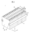
- FIG. 1 is a perspective view of a battery module according to a first embodiment of the present invention.
- FIG. 2A is a perspective view illustrating a terminal of the battery module of FIG. 1 and a bus-bar fastened to the terminal.
- FIG. 2B is an exploded perspective view of FIG. 2A .
- the battery module 1 includes a plurality of battery cells 10; a terminal 100 provided on the each of the battery cells 10 and having a fastening portion 102; and a bus-bar 110 fastened to the fastening portions 102 of neighboring battery cells 10 so that the neighboring battery cells 10 are electrically connected to each other.
- the battery cell 10 may include a battery case having one opened surface, and an electrode assembly and an electrolyte, accommodated in the battery case.
- the electrode assembly and the electrolyte generate energy by an electrochemical reaction, and the battery case is sealed by a cap plate 14.
- the cap plate 14 may be provided with the terminal 100, the bus-bar 110 fastened to the terminal 100, and a vent portion 13.
- the terminal 100 may be composed of positive and negative electrode terminals having different polarities from each other.
- the vent portion 13 is a safety means of the battery cell 10, and acts as a path through which gas generated in the inside of the battery cell 10 is exhausted to the outside of the battery cell 10.
- the positive and negative electrode terminals of the neighboring battery cells 10 may be electrically connected to each other through the bus-bar 110.
- the plurality of battery cells 10 may be aligned, and a housing 20 may be used to fix the alignment of the battery cells 10.
- the housing 20 may include end plates 21 and side plates 22.
- the end plates 21 are provided opposite to each other, so that each of the end plates 21 faces a long side surface that is a wide surface of an outermost battery cell 10.
- the side plates 22 connect the end plates 21 facing the respective outermost battery cells 10, and each of the side plates 22 faces short side surfaces that are narrow surfaces of the battery cells 10.
- the end plates 21 and the side plates 22 are used to fix the plurality of battery cells 10, and may be variously modified depending on the design of the battery module 1.
- the bus-bar 110 may be coupled to the terminal 100 through forcible insertion coupling.
- the bus-bar 110 and the terminal 100 are not connected by a fastener such as a bolt and a nut or connected by a method such as welding, and therefore, the connection structure between the bus-bar 100 and the terminal 100 may not be firmly maintained.
- the battery cells 10 are fixed by the housing 20 composed of the end plates 21 and the side plates 22, and thus the coupling force between the bus-bar 110 and the terminal can be firmly maintained.
- the bus-bar 110 and the terminal 100 may be additionally welded if necessary.
- the terminal 100 includes a terminal main body 101, the fastening portion 102 to which the bus-bar 110 is fastened, and a fastening window connected to the fastening portion 102 so as to check a fastening state between the bus-bar 100 and the fastening portion 102.
- the section of the fastening portion 102 in parallel with the gravity direction is formed in a rectangular shape, and the bus-bar 110 fastened to the fastening portion 102 is formed in the shape of a bar corresponding to the fastening portion 102.
- the bus-bar 110 coupled to the terminal 100 includes a bus-bar main body 111 and an extending portion 112 extended from the bus-bar main body 111 so as to be provided between the terminals 100.
- the extending portion 112 may serve as a kind of stopper, and the length of the bus-bar main body 111 substantially fastened to the fastening portion 102 may be adjusted due to the extending portion 112.
- bus-bars modified differently from the first embodiment of the present invention will be described with reference to FIGS. 3A to 3C .
- a first latching projection 113a having a shape corresponding to the fastening window 103 is further provided on a bus-bar main body 111 in a bus-bar 110a.
- the first latching projection 113a may be formed in a concave shape such as a concave lens.
- a second latching projection 114 is further provided in a region corresponding to the fastening window 103 on a bus-bar main body 111 in a bus-bar 110b.
- the second latching projection 114 may be formed in a shape composed of a plurality of projections.
- a fastening groove 116 provided between fastening ribs 115 is provided in at least a portion of a bus-bar main body 111 in a bus-bar 110c.
- a third latching projection 113c exposed to the fastening window 103 is further provided on the fastening rib 115.
- the first, second or third latching projection 113a, 114 or 113c shown in FIGS. 3A to 3C may be accommodated in a space secured by the fastening window 103 connected to the fastening portion 102.
- FIGS. 4 to 5B a battery module according to a second embodiment of the present invention will be described with reference to FIGS. 4 to 5B .
- the second embodiment descriptions of components identical or similar to those of the first embodiment will be omitted, and only components different from those of the first embodiment will be described.
- FIG. 4 is a perspective view of a battery module according to a second embodiment of the present invention.
- FIG. 5A is a perspective view illustrating a terminal of the battery module of FIG. 4 and a bus-bar fastened to the terminal.
- FIG. 5B is an exploded perspective view of FIG. 5A .
- the battery module 2 includes a plurality of battery cells 10; a terminal 200 provided on each of the battery cells 10 and having a fastening portion 202; and a bus-bar 210 fastened to the fastening portions 202 of neighboring battery cells 10 so that the neighboring battery cells 10 are electrically connected to each other.
- the battery cell 10 may include a battery case having one opened surface, and an electrode assembly and an electrolyte, accommodated in the battery case.
- the electrode assembly and the electrolyte generate energy by an electrochemical reaction, and the battery case is sealed by a cap plate 14.
- the cap plate 14 may be provided with the terminal 200, the bus-bar 210 fastened to the terminal 200, and a vent portion 13.
- the terminal 200 may be composed of positive and negative electrode terminals having different polarities from each other.
- the vent portion 13 is a safety means of the battery cell 10, and acts as a path through which gas generated in the inside of the battery cell 10 is exhausted to the outside of the battery cell 10.
- the positive and negative electrode terminals of the neighboring battery cells 10 may be electrically connected to each other through the bus-bar 210.
- the bus-bar 210 may be coupled to the terminal 200 through forcible insertion coupling.
- the bus-bar 210 and the terminal 200 are not connected by a fastener such as a bolt and a nut or connected by a method such as welding, and therefore, the connection structure between the bus-bar 200 and the terminal 200 may not be firmly maintained.
- the battery cells 10 are fixed by the housing 20 composed of the end plates 21 and the side plates 22, and thus the coupling force between the bus-bar 210 and the terminal can be firmly maintained.
- the bus-bar 210 and the terminal 200 may be additionally welded if necessary.
- the terminal 200 includes a terminal main body 201 and the fastening portion 202 to which the bus-bar 210 is fastened.
- the section of the fastening portion 202 in parallel with the gravity direction is formed in a circular shape, and the bus-bar 210 fastened to the fastening portion 202 is formed in the shape of a hollow rod corresponding to the fastening portion 202.
- the bus-bar 210 coupled to the terminal 200 includes a bus-bar main body 211 and an extending portion 212 extended from the bus-bar main body 211 so as to be provided between the terminals 200.
- the extending portion 212 may serve as a kind of stopper, and the length of the bus-bar main body 211 substantially fastened to the fastening portion 202 may be adjusted due to the extending portion 212.
- a fastening groove 216 provided between fastening ribs 215 is formed in at least a portion of the bus-bar main body 211.
- the bus-bar main body 211 can be flexibly fastened to the terminal 200 due to the fastening groove 216 provided between the fastening ribs 215.
- a battery module according to a third embodiment of the present invention will be described with reference to FIGS. 7 to 8B .
- descriptions of components identical or similar to those of the first and second embodiments will be omitted, and only components different from those of the first and second embodiments will be described.
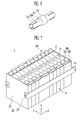
- FIG. 7 is a perspective view of a battery module according to a third embodiment of the present invention.
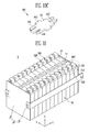
- FIG. 8A is a perspective view illustrating a terminal of the battery module of FIG. 7 and a bus-bar fastened to the terminal.
- FIG. 8B is an exploded perspective view of FIG. 8A .
- the battery module 3 includes a plurality of battery cells 10; a terminal 300 provided on each of the battery cells 10 and having a fastening portion 302; and a bus-bar 310 fastened to the fastening portions 302 of neighboring battery cells 10 so that the neighboring battery cells 10 are electrically connected to each other.
- the battery cell 10 may include a battery case having one opened surface, and an electrode assembly and an electrolyte, accommodated in the battery case.
- the electrode assembly and the electrolyte generate energy by an electrochemical reaction, and the battery case is sealed by a cap plate 14.
- the cap plate 14 may be provided with the terminal 300, the bus-bar 310 fastened to the terminal 300, and a vent portion 13.
- the terminal 300 may be composed of positive and negative electrode terminals having different polarities from each other.
- the vent portion 13 is a safety means of the battery cell 10, and acts as a path through which gas generated in the inside of the battery cell 10 is exhausted to the outside of the battery cell 10.
- the positive and negative electrode terminals of the neighboring battery cells 10 may be electrically connected to each other through the bus-bar 310.
- the bus-bar 310 may be coupled to the terminal 300 through forcible insertion coupling.
- the bus-bar 310 and the terminal 300 are not connected by a fastener such as a bolt and a nut or connected by a method such as welding, and therefore, the connection structure between the bus-bar 300 and the terminal 300 may not be firmly maintained.
- the battery cells 10 are fixed by the housing 20 composed of the end plates 21 and the side plates 22, and thus the coupling force between the bus-bar 310 and the terminal can be firmly maintained.
- the bus-bar 110 and the terminal 300 may be additionally welded if necessary.
- the terminal 300 includes a terminal main body 301 and the fastening portion 302 to which the bus-bar 310 is fastened.
- the section of the fastening portion 302 in parallel with the gravity direction is formed in a rectangular shape
- the bus-bar 310 fastened to the fastening portion 302 is formed in the shape of a bar corresponding to the fastening portion 302.
- the bus-bar 310 coupled to the terminals 300 includes a bus-bar main body 311 and extending portions 312 respectively extended from both sides of the bus-bar main body 311 so as to be fastened to the fastening portions 302 of the terminals 300.
- the extending portion 312 may serve as a kind of stopper, and the length of the bus-bar main body 311 substantially fastened to the fastening portion 302 may be adjusted due to the extending portion 312.
- the bus-bar 310 is fastened to the fastening portion 302 on the short side surface of the battery cell 10 so as to facilitate the fastening between the bus-bar 310 and the fastening portion 302.
- a battery module according to a fourth embodiment of the present invention will be described with reference to FIGS. 9 to 10B .
- descriptions of components identical or similar to those of the first to third embodiments will be omitted, and only components different from those of the first to third embodiments will be described.
- FIG. 9 is a perspective view of a battery module according to a fourth embodiment of the present invention.
- FIG. 10A is a plan view illustrating a terminal of the battery module of FIG. 9 and a bus-bar fastened to the terminal.
- FIG. 10B is an exploded perspective view showing a portion of FIG. 9 .
- the battery module 4 includes a plurality of battery cells 10; a terminal 400 provided on each of the battery cells 10 and having a fastening portion 402; and a bus-bar 410 fastened to the fastening portions 402 of neighboring battery cells 10 so that the neighboring battery cells 10 are electrically connected to each other.
- the battery cell 10 may include a battery case having one opened surface, and an electrode assembly and an electrolyte, accommodated in the battery case.
- the electrode assembly and the electrolyte generate energy by an electrochemical reaction, and the battery case is sealed by a cap plate 14.
- the cap plate 14 may be provided with the terminal 400, the bus-bar 410 fastened to the terminal 400, and a vent portion 13.
- the terminal 400 may be composed of positive and negative electrode terminals having different polarities from each other.
- the vent portion 13 is a safety means of the battery cell 10, and acts as a path through which gas generated in the inside of the battery cell 10 is exhausted to the outside of the battery cell 10.
- the positive and negative electrode terminals of the neighboring battery cells 10 may be electrically connected to each other through the bus-bar 410.
- the bus-bar 410 may be coupled to the terminal 400 through forcible insertion coupling.
- the bus-bar 410 and the terminal 400 are not connected by a fastener such as a bolt and a nut or connected by a method such as welding, and therefore, the connection structure between the bus-bar 400 and the terminal 400 may not be firmly maintained.
- the battery cells 10 are fixed by the housing 20 composed of the end plates 21 and the side plates 22, and thus the coupling force between the bus-bar 410 and the terminal can be firmly maintained.
- the bus-bar 410 and the terminal 400 may be additionally welded if necessary.
- the terminal 400 includes a terminal main body 401 and the fastening portion 402 to which the bus-bar 410 is fastened.
- the section of the fastening portion 402 in parallel with the gravity direction is formed in a rectangular shape, and the bus-bar 410 is fastened to the fastening portion 402.
- the bus-bar 410 coupled to the terminals 400 includes a bus-bar main body 411 and extending portions 412 respectively extended from both sides of the bus-bar main body 411 so as to be fastened to the fastening portions 402 of the terminals 400.
- the extending portion 412 may serve as a kind of stopper, and the length of the bus-bar main body 411 substantially fastened to the fastening portion 402 may be adjusted due to the extending portion 412.
- Fastening grooves 416 provided between fastening ribs 415 are formed at both sides of the bus-bar main body 411 in the bus-bar 410.
- the fastening rib 415 and fastening groove 416 of neighboring bus-bar main bodies 411 are complementary coupled so that the neighboring bus-bar main bodies are connected to each other.
- the bus-bar main body 411 can be flexibly fastened to the terminal 400 due to the fastening groove 416 provided between the fastening ribs 415.
- a battery module according to a fifth embodiment of the present invention will be described with reference to FIGS. 11 to 12B .
- descriptions of components identical or similar to those of the first to fourth embodiments will be omitted, and only components different from those of the first to fourth embodiments will be described.
- FIG. 11 is a perspective view of a battery module according to a fifth embodiment of the present invention.
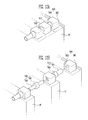
- FIG. 12A is a perspective view illustrating a terminal of the battery module of FIG. 11 and a bus-bar fastened to the terminal.
- FIG. 12B is an exploded perspective view of FIG. 12A .
- the battery module 5 includes a plurality of battery cells 10; a terminal 500 provided on each of the battery cells 10 and having a fastening portion 502; and a bus-bar 510 fastened to the fastening portions 502 of neighboring battery cells 10 so that the neighboring battery cells 10 are electrically connected to each other.
- an auxiliary bus-bar 520 is connected between neighboring bus-bars 510.
- the battery cell 10 may include a battery case having one opened surface, and an electrode assembly and an electrolyte, accommodated in the battery case.
- the electrode assembly and the electrolyte generate energy by an electrochemical reaction, and the battery case is sealed by a cap plate 14.
- the cap plate 14 may be provided with the terminal 500, the bus-bar 510 fastened to the terminal 500, and a vent portion 13.
- the terminal 500 may be composed of positive and negative electrode terminals having different polarities from each other.
- the vent portion 13 is a safety means of the battery cell 10, and acts as a path through which gas generated in the inside of the battery cell 10 is exhausted to the outside of the battery cell 10.
- the positive and negative electrode terminals of the neighboring battery cells 10 may be electrically connected to each other through the bus-bar 510.
- the bus-bar 510 may be coupled to the terminal 500 through forcible insertion coupling.
- the bus-bar 510 and the terminal 500 are not connected by a fastener such as a bolt and a nut or connected by a method such as welding, and therefore, the connection structure between the bus-bar 500 and the terminal 500 may not be firmly maintained.
- the battery cells 10 are fixed by the housing 20 composed of the end plates 21 and the side plates 22, and thus the coupling force between the bus-bar 510 and the terminal can be firmly maintained.
- the bus-bar 510 and the terminal 500 may be additionally welded if necessary.
- the terminal 500 includes a terminal main body 501 and the fastening portion 502 to which the bus-bar 510 is fastened.
- the section of the fastening portion 502 in parallel with the gravity direction is formed in a circular shape
- the bus-bar 510 fastened to the fastening portion 502 is formed in the shape of a hollow rod corresponding to the fastening portion 502.
- the auxiliary bus-bar 520 connecting neighboring bus-bars 510 is further provided between the neighboring bus-bars 510.
- the auxiliary bus-bar 520 is formed in the shape of a hollow rod, corresponding to the bus-bar 510 neighboring thereto. Therefore, the auxiliary bus-bar 520 may be coupled to the bus-bar 510 neighboring thereto so that an auxiliary bus-bar main body 521 of the auxiliary bus-bar 520 is forcibly inserted into the inside of the bus-bar 510.
- the bus-bar 510 coupled to the terminals 500 includes a bus-bar main body 511 and an extending portion 512 extended from the bus-bar main body 511 so as to be provided between the terminals 500.
- the auxiliary bus-bar 520 connecting the neighboring bus-bars 510 also includes the auxiliary bus-bar main body 521 and an auxiliary bus-bar extending portion 522 extended from the auxiliary bus-bar main body 521 so as to be provided between the terminals 500.
- the extending portion 512 and the auxiliary bus-bar extending portion 522 may serve as a kind of stopper, and the length of the bus-bar main body 511 substantially fastened to the fastening portion 502 may be adjusted due to the extending portion 512 and the auxiliary bus-bar extending portion 522.
Abstract
Description
- An aspect of the present invention relates to a battery module, and more particularly, to a battery module having a terminal member of a new structure.
- A high-power battery module using a non-aqueous electrolyte with high energy density has recently been developed. The high-power battery module is configured as a large-capacity battery module manufactured by connecting a plurality of battery cells in series so as to be used in driving motors of devices requiring high power, e.g., electric vehicles and the like.
- Typically, the battery module may include a plurality of battery cells, and neighboring battery cells are electrically connected by a bus-bar. Conventionally, the bus-bar connected neighboring battery cells through a fastening structure such as a bolt and a nut. Recently, various studies have been conducted to simplify the fastening structure of the bus-bar described above.
- Embodiments provide a battery module capable of simplifying the fastening structure of a bus-bar through a simple structural modification.
- Embodiments also provide a battery module capable of reducing production cost and improving processing efficiency.
- According to an aspect of the present invention, a battery module including: a plurality of battery cells fixed by a housing; a terminal provided on each of the battery cells and having a fastening portion; and a bus-bar fastened to the fastening portions of neighboring battery cells through forcible insertion so that the neighboring battery cells are electrically connected to each other. The forcible insertion results in a coupling fastening the battery cells against relative movements to each other in an insertion direction or in an direction opposite to the insertion direction. This coupling is firmly maintained since cells are further fixed by the housing.
- The terminal may include a terminal main body, the fastening portion to which the bus-bar is fastened, and a fastening window connected to the fastening portion so as to check a fastening state between the bus-bar and the fastening portion.
- The section of the fastening portion in parallel with the gravity direction may be formed in a rectangular shape along a direction being perpendicular to an insertion direction. That is, the section of the fastening portion perpendicular to the insertion direction, the section being in parallel with the gravity direction if the battery module is properly positioned, may be formed in the rectangular shape.
- The bus-bar may include a bus-bar main body and an extending portion extended from the bus-bar main body so as to be provided between the terminals. That is, bus-bar main body preferably may extend in the insertion direction and insertion direction of the bus-bar main body into one of the fastening portions is opposite to insertion direction of the bus-bar main body into another one of the fastening portions.
- The battery module may further include a first latching projection provided on the bus-bar main body and having a shape corresponding to that of the fastening window.
- The battery module may further include a second latching projection provided on the bus-bar main body and having a plurality of projections in a region corresponding to the fastening window.
- The bus-bar may include fastening ribs provided in at least a portion of the bus-bar main body and a fastening groove provided between the fastening ribs.
- The battery module may further include a third latching projection provided on the fastening rib and exposed to the fastening window.
- The bus-bar may be formed in the shape of a bar.
- The terminal may include a terminal main body and the fastening portion to which the bus-bar is fastened.
- The section of the fastening portion in parallel with the gravity direction is formed in a circular or elliptical shape along a direction being perpendicular to an insertion direction. That is, the section of the fastening portion perpendicular to the insertion direction, the section being in parallel with the gravity direction if the battery module is properly positioned, may be formed in the circular or elliptical shape.
- The bus-bar may be formed in the shape of a hollow rod.
- The battery module may further include an auxiliary bus-bar inserted into neighboring bus-bars, wherein an outer diameter of a bus-bar main body of the auxiliary bus-bar corresponds to an inner diameter of the bus-bar main body of the neighboring bus-bar. Preferably, the auxiliary bus-bar is inserted into the neighboring bus-bars within the fastening portion.
- The fastening rib and the fastening groove may be provided to both sides of the bus-bar main body.
- The fastening rib and the fastening groove of neighboring bus-bar main bodies may be complementary coupled to each other.
- The bus-bar may include a bus-bar main body and extending portions to be fastened to the fastening portions respectively, wherein the extending portions extend from both sides of the bus-bar main body in a perpendicular direction so as to provide the bus-bar with a U-shape. That is, bus-bar main body preferably may extend perpendicularly to the insertion direction into one of the fastening portions which is the same as insertion direction into another one of the fastening portions.
- As described above, according to the present invention, it is possible to provide a battery module capable of simplifying the fastening structure of a bus-bar through a simple structural modification.
- Further, the fastening structure of the bus-bar is simplified, so that it is possible to reduce production cost and to improve processing efficiency.
- The accompanying drawings, together with the specification, illustrate exemplary embodiments of the present invention, and, together with the description, serve to explain the principles of the present invention.
-
FIG. 1 is a perspective view of a battery module according to a first embodiment of the present invention. -
FIG. 2A is a perspective view illustrating a terminal of the battery module ofFIG. 1 and a bus-bar fastened to the terminal. -
FIG. 2B is an exploded perspective view ofFIG. 2A . -
FIGS. 3A to 3C are enlarged perspective views showing bus-bars modified differently from the first embodiment of the present invention. -
FIG. 4 is a perspective view of a battery module according to a second embodiment of the present invention. -
FIG. 5A is a perspective view illustrating a terminal of the battery module ofFIG. 4 and a bus-bar fastened to the terminal. -
FIG. 5B is an exploded perspective view ofFIG. 5A . -
FIG. 6 is an enlarge perspective view showing a bus-bar modified differently from the second embodiment of the present invention. -
FIG. 7 is a perspective view of a battery module according to a third embodiment of the present invention. -
FIG. 8A is a perspective view illustrating a terminal of the battery module ofFIG. 7 and a bus-bar fastened to the terminal. -
FIG. 8B is an exploded perspective view ofFIG. 8A . -
FIG. 9 is a perspective view of a battery module according to a fourth embodiment of the present invention. -
FIG. 10A is a plan view illustrating a terminal of the battery module ofFIG. 9 and a bus-bar fastened to the terminal. -
FIG. 10B is an exploded perspective view showing a portion ofFIG. 9 . -
FIG. 11 is a perspective view of a battery module according to a fifth embodiment of the present invention. -
FIG. 12A is a perspective view illustrating a terminal of the battery module ofFIG. 11 and a bus-bar fastened to the terminal. -
FIG. 12B is an exploded perspective view ofFIG. 12A . - In the following detailed description, only certain exemplary embodiments of the present invention have been shown and described, simply by way of illustration. As those skilled in the art would realize, the described embodiments may be modified in various different ways, all without departing from the spirit or scope of the present invention. Accordingly, the drawings and description are to be regarded as illustrative in nature and not restrictive. In addition, when an element is referred to as being "on" another element, it can be directly on the another element or be indirectly on the another element with one or more intervening elements interposed therebetween. Also, when an element is referred to as being "connected to" another element, it can be directly connected to the another element or be indirectly connected to the another element with one or more intervening elements interposed therebetween. Hereinafter, like reference numerals refer to like elements.
- Exemplary embodiments of the present invention will be described with reference to the accompanying drawings.
-
FIG. 1 is a perspective view of a battery module according to a first embodiment of the present invention.FIG. 2A is a perspective view illustrating a terminal of the battery module ofFIG. 1 and a bus-bar fastened to the terminal.FIG. 2B is an exploded perspective view ofFIG. 2A . - Referring to
FIG. 1 , thebattery module 1 according to the first embodiment of the present invention includes a plurality ofbattery cells 10; a terminal 100 provided on the each of thebattery cells 10 and having afastening portion 102; and a bus-bar 110 fastened to thefastening portions 102 of neighboringbattery cells 10 so that the neighboringbattery cells 10 are electrically connected to each other. - The
battery cell 10 may include a battery case having one opened surface, and an electrode assembly and an electrolyte, accommodated in the battery case. The electrode assembly and the electrolyte generate energy by an electrochemical reaction, and the battery case is sealed by acap plate 14. Thecap plate 14 may be provided with the terminal 100, the bus-bar 110 fastened to the terminal 100, and avent portion 13. The terminal 100 may be composed of positive and negative electrode terminals having different polarities from each other. Thevent portion 13 is a safety means of thebattery cell 10, and acts as a path through which gas generated in the inside of thebattery cell 10 is exhausted to the outside of thebattery cell 10. The positive and negative electrode terminals of the neighboringbattery cells 10 may be electrically connected to each other through the bus-bar 110. - The plurality of
battery cells 10 may be aligned, and ahousing 20 may be used to fix the alignment of thebattery cells 10. Thehousing 20 may includeend plates 21 andside plates 22. Theend plates 21 are provided opposite to each other, so that each of theend plates 21 faces a long side surface that is a wide surface of anoutermost battery cell 10. Theside plates 22 connect theend plates 21 facing the respectiveoutermost battery cells 10, and each of theside plates 22 faces short side surfaces that are narrow surfaces of thebattery cells 10. Theend plates 21 and theside plates 22 are used to fix the plurality ofbattery cells 10, and may be variously modified depending on the design of thebattery module 1. - The bus-
bar 110 according to the first embodiment of the present invention may be coupled to the terminal 100 through forcible insertion coupling. In this case, the bus-bar 110 and the terminal 100 are not connected by a fastener such as a bolt and a nut or connected by a method such as welding, and therefore, the connection structure between the bus-bar 100 and the terminal 100 may not be firmly maintained. However, thebattery cells 10 are fixed by thehousing 20 composed of theend plates 21 and theside plates 22, and thus the coupling force between the bus-bar 110 and the terminal can be firmly maintained. After the bus-bar 110 and the terminal 100 are coupled to each other, the bus-bar 110 and the terminal 100 may be additionally welded if necessary. - Referring to
FIGS. 2A and 2B , the terminal 100 according to the first embodiment of the present invention includes a terminalmain body 101, thefastening portion 102 to which the bus-bar 110 is fastened, and a fastening window connected to thefastening portion 102 so as to check a fastening state between the bus-bar 100 and thefastening portion 102. Here, the section of thefastening portion 102 in parallel with the gravity direction is formed in a rectangular shape, and the bus-bar 110 fastened to thefastening portion 102 is formed in the shape of a bar corresponding to thefastening portion 102. - The bus-
bar 110 coupled to the terminal 100 includes a bus-barmain body 111 and an extendingportion 112 extended from the bus-barmain body 111 so as to be provided between theterminals 100. Here, the extendingportion 112 may serve as a kind of stopper, and the length of the bus-barmain body 111 substantially fastened to thefastening portion 102 may be adjusted due to the extendingportion 112. - Hereinafter, bus-bars modified differently from the first embodiment of the present invention will be described with reference to
FIGS. 3A to 3C . - Referring to
FIG. 3A , afirst latching projection 113a having a shape corresponding to thefastening window 103 is further provided on a bus-barmain body 111 in a bus-bar 110a. Thefirst latching projection 113a may be formed in a concave shape such as a concave lens. - Referring to
FIG. 3B , a second latching projection 114 is further provided in a region corresponding to thefastening window 103 on a bus-barmain body 111 in a bus-bar 110b. The second latching projection 114 may be formed in a shape composed of a plurality of projections. - Referring to
FIG. 3C , afastening groove 116 provided betweenfastening ribs 115 is provided in at least a portion of a bus-barmain body 111 in a bus-bar 110c. Athird latching projection 113c exposed to thefastening window 103 is further provided on thefastening rib 115. - The first, second or
third latching projection FIGS. 3A to 3C may be accommodated in a space secured by thefastening window 103 connected to thefastening portion 102. - Hereinafter, a battery module according to a second embodiment of the present invention will be described with reference to
FIGS. 4 to 5B . In the second embodiment, descriptions of components identical or similar to those of the first embodiment will be omitted, and only components different from those of the first embodiment will be described. -
FIG. 4 is a perspective view of a battery module according to a second embodiment of the present invention.FIG. 5A is a perspective view illustrating a terminal of the battery module ofFIG. 4 and a bus-bar fastened to the terminal.FIG. 5B is an exploded perspective view ofFIG. 5A . - Referring to
FIG. 4 , the battery module 2 according to the second embodiment of the present invention includes a plurality ofbattery cells 10; a terminal 200 provided on each of thebattery cells 10 and having afastening portion 202; and a bus-bar 210 fastened to thefastening portions 202 of neighboringbattery cells 10 so that the neighboringbattery cells 10 are electrically connected to each other. - The
battery cell 10 may include a battery case having one opened surface, and an electrode assembly and an electrolyte, accommodated in the battery case. The electrode assembly and the electrolyte generate energy by an electrochemical reaction, and the battery case is sealed by acap plate 14. Thecap plate 14 may be provided with the terminal 200, the bus-bar 210 fastened to the terminal 200, and avent portion 13. The terminal 200 may be composed of positive and negative electrode terminals having different polarities from each other. Thevent portion 13 is a safety means of thebattery cell 10, and acts as a path through which gas generated in the inside of thebattery cell 10 is exhausted to the outside of thebattery cell 10. The positive and negative electrode terminals of the neighboringbattery cells 10 may be electrically connected to each other through the bus-bar 210. - The bus-
bar 210 according to the second embodiment of the present invention may be coupled to the terminal 200 through forcible insertion coupling. In this case, the bus-bar 210 and the terminal 200 are not connected by a fastener such as a bolt and a nut or connected by a method such as welding, and therefore, the connection structure between the bus-bar 200 and the terminal 200 may not be firmly maintained. However, thebattery cells 10 are fixed by thehousing 20 composed of theend plates 21 and theside plates 22, and thus the coupling force between the bus-bar 210 and the terminal can be firmly maintained. After the bus-bar 210 and the terminal 200 are coupled to each other, the bus-bar 210 and the terminal 200 may be additionally welded if necessary. - Referring to
FIGS. 5A and 5B , the terminal 200 according to the second embodiment of the present invention includes a terminalmain body 201 and thefastening portion 202 to which the bus-bar 210 is fastened. Here, the section of thefastening portion 202 in parallel with the gravity direction is formed in a circular shape, and the bus-bar 210 fastened to thefastening portion 202 is formed in the shape of a hollow rod corresponding to thefastening portion 202. - The bus-
bar 210 coupled to the terminal 200 includes a bus-barmain body 211 and an extendingportion 212 extended from the bus-barmain body 211 so as to be provided between theterminals 200. Here, the extendingportion 212 may serve as a kind of stopper, and the length of the bus-barmain body 211 substantially fastened to thefastening portion 202 may be adjusted due to the extendingportion 212. - Hereinafter, a bus-bar modified differently from the second embodiment of the present invention will be described with reference to
FIG. 6 . - A
fastening groove 216 provided betweenfastening ribs 215 is formed in at least a portion of the bus-barmain body 211. The bus-barmain body 211 can be flexibly fastened to the terminal 200 due to thefastening groove 216 provided between thefastening ribs 215. - Hereinafter, a battery module according to a third embodiment of the present invention will be described with reference to
FIGS. 7 to 8B . In the third embodiment, descriptions of components identical or similar to those of the first and second embodiments will be omitted, and only components different from those of the first and second embodiments will be described. -
FIG. 7 is a perspective view of a battery module according to a third embodiment of the present invention.FIG. 8A is a perspective view illustrating a terminal of the battery module ofFIG. 7 and a bus-bar fastened to the terminal.FIG. 8B is an exploded perspective view ofFIG. 8A . - Referring to
FIG. 7 , thebattery module 3 according to the third embodiment of the present invention includes a plurality ofbattery cells 10; a terminal 300 provided on each of thebattery cells 10 and having afastening portion 302; and a bus-bar 310 fastened to thefastening portions 302 of neighboringbattery cells 10 so that the neighboringbattery cells 10 are electrically connected to each other. - The
battery cell 10 may include a battery case having one opened surface, and an electrode assembly and an electrolyte, accommodated in the battery case. The electrode assembly and the electrolyte generate energy by an electrochemical reaction, and the battery case is sealed by acap plate 14. Thecap plate 14 may be provided with the terminal 300, the bus-bar 310 fastened to the terminal 300, and avent portion 13. The terminal 300 may be composed of positive and negative electrode terminals having different polarities from each other. Thevent portion 13 is a safety means of thebattery cell 10, and acts as a path through which gas generated in the inside of thebattery cell 10 is exhausted to the outside of thebattery cell 10. The positive and negative electrode terminals of the neighboringbattery cells 10 may be electrically connected to each other through the bus-bar 310. - The bus-
bar 310 according to the third embodiment of the present invention may be coupled to the terminal 300 through forcible insertion coupling. In this case, the bus-bar 310 and the terminal 300 are not connected by a fastener such as a bolt and a nut or connected by a method such as welding, and therefore, the connection structure between the bus-bar 300 and the terminal 300 may not be firmly maintained. However, thebattery cells 10 are fixed by thehousing 20 composed of theend plates 21 and theside plates 22, and thus the coupling force between the bus-bar 310 and the terminal can be firmly maintained. After the bus-bar 310 and the terminal 300 are coupled to each other, the bus-bar 110 and the terminal 300 may be additionally welded if necessary. - Referring to
FIGS. 8A and 8B , the terminal 300 according to the third embodiment of the present invention includes a terminalmain body 301 and thefastening portion 302 to which the bus-bar 310 is fastened. Here, the section of thefastening portion 302 in parallel with the gravity direction is formed in a rectangular shape, and the bus-bar 310 fastened to thefastening portion 302 is formed in the shape of a bar corresponding to thefastening portion 302. - The bus-
bar 310 coupled to theterminals 300 includes a bus-barmain body 311 and extendingportions 312 respectively extended from both sides of the bus-barmain body 311 so as to be fastened to thefastening portions 302 of theterminals 300. Here, the extendingportion 312 may serve as a kind of stopper, and the length of the bus-barmain body 311 substantially fastened to thefastening portion 302 may be adjusted due to the extendingportion 312. The bus-bar 310 is fastened to thefastening portion 302 on the short side surface of thebattery cell 10 so as to facilitate the fastening between the bus-bar 310 and thefastening portion 302. - Hereinafter, a battery module according to a fourth embodiment of the present invention will be described with reference to
FIGS. 9 to 10B . In the fourth embodiment, descriptions of components identical or similar to those of the first to third embodiments will be omitted, and only components different from those of the first to third embodiments will be described. -
FIG. 9 is a perspective view of a battery module according to a fourth embodiment of the present invention.FIG. 10A is a plan view illustrating a terminal of the battery module ofFIG. 9 and a bus-bar fastened to the terminal.FIG. 10B is an exploded perspective view showing a portion ofFIG. 9 . - Referring to
FIG. 9 , the battery module 4 according to the fourth embodiment of the present invention includes a plurality ofbattery cells 10; a terminal 400 provided on each of thebattery cells 10 and having afastening portion 402; and a bus-bar 410 fastened to thefastening portions 402 of neighboringbattery cells 10 so that the neighboringbattery cells 10 are electrically connected to each other. - The
battery cell 10 may include a battery case having one opened surface, and an electrode assembly and an electrolyte, accommodated in the battery case. The electrode assembly and the electrolyte generate energy by an electrochemical reaction, and the battery case is sealed by acap plate 14. Thecap plate 14 may be provided with the terminal 400, the bus-bar 410 fastened to the terminal 400, and avent portion 13. The terminal 400 may be composed of positive and negative electrode terminals having different polarities from each other. Thevent portion 13 is a safety means of thebattery cell 10, and acts as a path through which gas generated in the inside of thebattery cell 10 is exhausted to the outside of thebattery cell 10. The positive and negative electrode terminals of the neighboringbattery cells 10 may be electrically connected to each other through the bus-bar 410. - The bus-
bar 410 according to the fourth embodiment of the present invention may be coupled to the terminal 400 through forcible insertion coupling. In this case, the bus-bar 410 and the terminal 400 are not connected by a fastener such as a bolt and a nut or connected by a method such as welding, and therefore, the connection structure between the bus-bar 400 and the terminal 400 may not be firmly maintained. However, thebattery cells 10 are fixed by thehousing 20 composed of theend plates 21 and theside plates 22, and thus the coupling force between the bus-bar 410 and the terminal can be firmly maintained. After the bus-bar 410 and the terminal 400 are coupled to each other, the bus-bar 410 and the terminal 400 may be additionally welded if necessary. - Referring to
FIGS. 10A and 10B , the terminal 400 according to the fourth embodiment of the present invention includes a terminalmain body 401 and thefastening portion 402 to which the bus-bar 410 is fastened. Here, the section of thefastening portion 402 in parallel with the gravity direction is formed in a rectangular shape, and the bus-bar 410 is fastened to thefastening portion 402. - The bus-
bar 410 coupled to theterminals 400 includes a bus-barmain body 411 and extendingportions 412 respectively extended from both sides of the bus-barmain body 411 so as to be fastened to thefastening portions 402 of theterminals 400. Here, the extendingportion 412 may serve as a kind of stopper, and the length of the bus-barmain body 411 substantially fastened to thefastening portion 402 may be adjusted due to the extendingportion 412. - Fastening
grooves 416 provided betweenfastening ribs 415 are formed at both sides of the bus-barmain body 411 in the bus-bar 410. Here, thefastening rib 415 andfastening groove 416 of neighboring bus-barmain bodies 411 are complementary coupled so that the neighboring bus-bar main bodies are connected to each other. The bus-barmain body 411 can be flexibly fastened to the terminal 400 due to thefastening groove 416 provided between thefastening ribs 415. - Hereinafter, a battery module according to a fifth embodiment of the present invention will be described with reference to
FIGS. 11 to 12B . In the fifth embodiment, descriptions of components identical or similar to those of the first to fourth embodiments will be omitted, and only components different from those of the first to fourth embodiments will be described. -
FIG. 11 is a perspective view of a battery module according to a fifth embodiment of the present invention.FIG. 12A is a perspective view illustrating a terminal of the battery module ofFIG. 11 and a bus-bar fastened to the terminal.FIG. 12B is an exploded perspective view ofFIG. 12A . - Referring to
FIG. 11 , the battery module 5 according to the fifth embodiment of the present invention includes a plurality ofbattery cells 10; a terminal 500 provided on each of thebattery cells 10 and having afastening portion 502; and a bus-bar 510 fastened to thefastening portions 502 of neighboringbattery cells 10 so that the neighboringbattery cells 10 are electrically connected to each other. Here, an auxiliary bus-bar 520 is connected between neighboring bus-bars 510. - The
battery cell 10 may include a battery case having one opened surface, and an electrode assembly and an electrolyte, accommodated in the battery case. The electrode assembly and the electrolyte generate energy by an electrochemical reaction, and the battery case is sealed by acap plate 14. Thecap plate 14 may be provided with the terminal 500, the bus-bar 510 fastened to the terminal 500, and avent portion 13. The terminal 500 may be composed of positive and negative electrode terminals having different polarities from each other. Thevent portion 13 is a safety means of thebattery cell 10, and acts as a path through which gas generated in the inside of thebattery cell 10 is exhausted to the outside of thebattery cell 10. The positive and negative electrode terminals of the neighboringbattery cells 10 may be electrically connected to each other through the bus-bar 510. - The bus-
bar 510 according to the fifth embodiment of the present invention may be coupled to the terminal 500 through forcible insertion coupling. In this case, the bus-bar 510 and the terminal 500 are not connected by a fastener such as a bolt and a nut or connected by a method such as welding, and therefore, the connection structure between the bus-bar 500 and the terminal 500 may not be firmly maintained. However, thebattery cells 10 are fixed by thehousing 20 composed of theend plates 21 and theside plates 22, and thus the coupling force between the bus-bar 510 and the terminal can be firmly maintained. After the bus-bar 510 and the terminal 500 are coupled to each other, the bus-bar 510 and the terminal 500 may be additionally welded if necessary. - Referring to
FIGS. 12A and 12B , the terminal 500 according to the fifth embodiment of the present invention includes a terminalmain body 501 and thefastening portion 502 to which the bus-bar 510 is fastened. Here, the section of thefastening portion 502 in parallel with the gravity direction is formed in a circular shape, and the bus-bar 510 fastened to thefastening portion 502 is formed in the shape of a hollow rod corresponding to thefastening portion 502. Here, the auxiliary bus-bar 520 connecting neighboring bus-bars 510 is further provided between the neighboring bus-bars 510. The auxiliary bus-bar 520 is formed in the shape of a hollow rod, corresponding to the bus-bar 510 neighboring thereto. Therefore, the auxiliary bus-bar 520 may be coupled to the bus-bar 510 neighboring thereto so that an auxiliary bus-barmain body 521 of the auxiliary bus-bar 520 is forcibly inserted into the inside of the bus-bar 510. - The bus-
bar 510 coupled to theterminals 500 includes a bus-barmain body 511 and an extendingportion 512 extended from the bus-barmain body 511 so as to be provided between theterminals 500. The auxiliary bus-bar 520 connecting the neighboring bus-bars 510 also includes the auxiliary bus-barmain body 521 and an auxiliary bus-bar extending portion 522 extended from the auxiliary bus-barmain body 521 so as to be provided between theterminals 500. Here, the extendingportion 512 and the auxiliary bus-bar extending portion 522 may serve as a kind of stopper, and the length of the bus-barmain body 511 substantially fastened to thefastening portion 502 may be adjusted due to the extendingportion 512 and the auxiliary bus-bar extending portion 522. - While the present invention has been described in connection with certain exemplary embodiments, it is to be understood that the invention is not limited to the disclosed embodiments, but, on the contrary, is intended to cover various modifications and equivalent arrangements included within the spirit and scope of the appended claims, and equivalents thereof.
Claims (15)
- A battery module (1) including: a plurality of battery cells (10) fixed by a housing (20); a terminal (100, 200, 300, 400, 500) provided on each of the battery cells (10) and having a fastening portion (102, 202, 302, 402, 502); and a bus-bar (110a, 110b, 110c, 210, 310, 410, 510) fastened to the fastening portions (102, 202, 302, 402, 502) of neighboring battery cells (10) through forcible insertion coupling so that the neighboring battery cells (10) are electrically connected to each other.
- The battery module (1) according to claim 1, wherein a fastening window (103) is connected to the fastening portion (102) so as to check a fastening state between the bus-bar (110a, 110b, 110c) and the fastening portion (102).
- The battery module (1) according to claim 1 or 2, wherein a section of the fastening portion (102, 302, 402) is formed in a rectangular shape along a direction being perpendicular to an insertion direction.
- The battery module (1) according to claim 2 or 3 wherein the bus-bar (110) includes a first latching projection (113a) provided on a bus-bar main body (111) and having a shape corresponding to that of the fastening window (102).
- The battery module (1) according to claim 2 or 3, wherein the bus-bar (110) includes a second latching projection (113b) provided on a bus-bar main body (111) and having a plurality of projections in a region corresponding to the fastening window (102).
- The battery module (1) according to claim 2 or 3, wherein the bus-bar (110) includes fastening ribs (115, 415) provided in at least a portion of a bus-bar main body and a fastening groove (116, 416) provided between the fastening ribs.
- The battery module (1) according to claim 6, wherein the fastening rib (115, 215, 415) and the fastening groove (116, 416) are provided to both sides of the bus-bar main body.
- The battery module (1) according to one of claims 6 and 7, wherein the bus-bar (110) includes a third latching projection (113c) provided on the fastening rib (115) and exposed to the fastening window (102).
- The battery module (1) according to claim 7 or 8, wherein the fastening rib (415) and the fastening groove (416) of neighboring bus-bar main bodies (410) are complementary coupled to each other.
- The battery module (1) according to claim 1, wherein a section of the fastening portion (202, 502) is formed in a circular or elliptical shape along a direction being perpendicular to an insertion direction.
- The battery module (1) according to claim 10, wherein the bus-bar (210, 510) is formed in the shape of a hollow rod.
- The battery module (1) according to claim 10 or 11, wherein the bus-bar includes fastening ribs (215) provided on both sides of a bus-bar main body and fastening grooves (216) provided on both sides between the fastening ribs (215).
- The battery module (1) according to claim 11, wherein the battery module (1) further includes an auxiliary bus-bar (520) inserted into neighboring bus-bars (510) within the fastening portion, wherein an outer diameter of the bus-bar main body (521) of the auxiliary bus-bar (520) corresponds to an inner diameter of the bus-bar main body (511) of the neighboring bus-bar (510).
- The battery module (1) according to one of claims 5-9 and 12, wherein the bus-bar (110a, 110b, 110c, 210, 410, 510) includes the bus-bar main body (111, 211, 411, 511) and at least one extending portion (112, 212, 412, 512) extended from the bus-bar main body so as to be provided between the terminals.
- The battery module (1) according to claim 1, wherein the bus-bar (310) includes a bus-bar main body (311) and extending portions (312) to be fastened to the fastening portions respectively, wherein the extending portions (312) extend from both sides of the bus-bar main body (311) in a perpendicular direction such that the bus-bar (310) has a U-shape .
Applications Claiming Priority (2)
| Application Number | Priority Date | Filing Date | Title |
|---|---|---|---|
| US201261619675P | 2012-04-03 | 2012-04-03 | |
| US13/559,364 US20130260611A1 (en) | 2012-04-03 | 2012-07-26 | Battery module |
Publications (2)
| Publication Number | Publication Date |
|---|---|
| EP2648243A1 true EP2648243A1 (en) | 2013-10-09 |
| EP2648243B1 EP2648243B1 (en) | 2015-10-07 |
Family
ID=46650409
Family Applications (1)
| Application Number | Title | Priority Date | Filing Date |
|---|---|---|---|
| EP12179784.9A Not-in-force EP2648243B1 (en) | 2012-04-03 | 2012-08-09 | Battery module |
Country Status (4)
| Country | Link |
|---|---|
| US (1) | US20130260611A1 (en) |
| EP (1) | EP2648243B1 (en) |
| JP (1) | JP2013214498A (en) |
| CN (1) | CN103367686A (en) |
Cited By (3)
| Publication number | Priority date | Publication date | Assignee | Title |
|---|---|---|---|---|
| WO2021123716A1 (en) * | 2019-12-19 | 2021-06-24 | Dyson Technology Limited | Battery pack |
| EP4123793A1 (en) * | 2021-07-23 | 2023-01-25 | Samsung SDI Co., Ltd. | A battery module, a battery pack, an electric vehicle, and a method of mounting a battery module |
| EP4131304A4 (en) * | 2020-03-31 | 2024-02-28 | Panasonic Ip Man Co Ltd | Electrical storage module |
Families Citing this family (27)
| Publication number | Priority date | Publication date | Assignee | Title |
|---|---|---|---|---|
| DE102011082576A1 (en) * | 2011-09-13 | 2013-03-14 | Bayerische Motoren Werke Aktiengesellschaft | Arrangement for fixing an energy storage module on a module carrier |
| JP5610012B2 (en) * | 2013-03-08 | 2014-10-22 | 株式会社豊田自動織機 | Battery module |
| US9660244B2 (en) | 2013-09-06 | 2017-05-23 | Johnson Controls Technology Company | System and method for establishing connections of a battery module |
| DE102013017249B4 (en) * | 2013-10-17 | 2021-09-09 | Kostal Kontakt Systeme Gmbh | Connector arrangement for the electrical coupling of battery modules and battery module arrangement |
| KR102221801B1 (en) * | 2014-02-04 | 2021-03-02 | 삼성에스디아이 주식회사 | Busbar module |
| DE102014103128A1 (en) * | 2014-03-10 | 2015-09-10 | Karlsruher Institut für Technologie | Connector for the electrical contacting of arresters of an electrochemical cell |
| US10497909B2 (en) | 2014-09-05 | 2019-12-03 | Ford Global Technologies, Llc | Battery assembly with snap-in arrays |
| WO2016164410A1 (en) * | 2015-04-10 | 2016-10-13 | Maxwell Technologies, Inc. | Reduced temperature energy storage device |
| US9853277B2 (en) * | 2015-06-19 | 2017-12-26 | Ford Global Technologies, Llc | Bus bar assembly including biased bus bar |
| KR102435380B1 (en) * | 2015-12-04 | 2022-08-23 | 삼성에스디아이 주식회사 | Rechargeable Secondary Battery |
| US10876510B2 (en) | 2016-03-02 | 2020-12-29 | Gentherm Incorporated | Systems and methods for supplying power in a hybrid vehicle using capacitors, a battery and one or more DC/DC converters |
| US10886583B2 (en) | 2016-03-02 | 2021-01-05 | Gentherm Incorporated | Battery and capacitor assembly for a vehicle and a method for heating and cooling the battery and capacitor assembly |
| DE102016204681A1 (en) * | 2016-03-22 | 2017-09-28 | Robert Bosch Gmbh | Battery and method of manufacturing a battery |
| CN105810873B (en) * | 2016-05-31 | 2018-06-05 | 华霆(合肥)动力技术有限公司 | A kind of soft-package battery module with separate assembling collector plate |
| CN205863277U (en) * | 2016-08-12 | 2017-01-04 | 宁德时代新能源科技股份有限公司 | Bus structure and battery |
| JP6699464B2 (en) * | 2016-09-05 | 2020-05-27 | 株式会社オートネットワーク技術研究所 | Connection module |
| CN206099077U (en) * | 2016-09-30 | 2017-04-12 | 比亚迪股份有限公司 | Power supply cabinet |
| KR102110543B1 (en) * | 2017-03-22 | 2020-05-13 | 주식회사 엘지화학 | Battery pack |
| JP6709757B2 (en) * | 2017-06-20 | 2020-06-17 | 矢崎総業株式会社 | Busbar structure |
| US10720619B2 (en) * | 2017-10-16 | 2020-07-21 | Ford Global Technologies, Llc | Array frame mounting inserts for securing battery assemblies |
| DE102017221769A1 (en) * | 2017-12-04 | 2019-06-06 | Bayerische Motoren Werke Aktiengesellschaft | Battery module for a high-voltage battery of a motor vehicle, high-voltage battery and motor vehicle |
| KR102598260B1 (en) | 2018-06-12 | 2023-11-02 | 삼성에스디아이 주식회사 | Battery module |
| JP7119762B2 (en) * | 2018-08-22 | 2022-08-17 | トヨタ自動車株式会社 | connection module |
| US11165266B2 (en) * | 2018-10-19 | 2021-11-02 | Systematic Power Solutions, LLC | Method of providing charge for a mechanical object |
| KR102321794B1 (en) * | 2018-12-05 | 2021-11-04 | 주식회사 엘지에너지솔루션 | Battery module including connector having bidirectional coupling structure |
| CN116937081A (en) * | 2022-03-31 | 2023-10-24 | 宁德时代新能源科技股份有限公司 | Electrode terminal, electrode post assembly, battery and electric equipment |
| EP4297149A1 (en) * | 2022-06-21 | 2023-12-27 | Newfrey LLC | Busbar assembly |
Citations (7)
| Publication number | Priority date | Publication date | Assignee | Title |
|---|---|---|---|---|
| US4156552A (en) * | 1977-09-02 | 1979-05-29 | The United Sates Of America As Represented By The Secretary Of The Navy | Quick disconnect intercell busbar for deep submergence batteries |
| US5496657A (en) * | 1994-03-16 | 1996-03-05 | Dixon, Jr.; Alfred R. | Modular battery system comprising individual interconnected modules |
| US5662497A (en) * | 1995-11-03 | 1997-09-02 | New York State Electric & Gas Corporation | Modular battery terminal connector assembly |
| US20070026306A1 (en) * | 2005-07-29 | 2007-02-01 | Gun-Goo Lee | Battery module |
| US20100266889A1 (en) * | 2009-04-16 | 2010-10-21 | Yongsam Kim | Secondary battery module |
| DE102009025579A1 (en) * | 2009-06-19 | 2010-12-23 | Li-Tec Battery Gmbh | Battery assembly and method for its preparation |
| US20120058383A1 (en) * | 2010-09-03 | 2012-03-08 | Mitsubishi Heavy Industries, Ltd. | Assembled battery |
Family Cites Families (6)
| Publication number | Priority date | Publication date | Assignee | Title |
|---|---|---|---|---|
| JP4171873B2 (en) * | 2002-02-25 | 2008-10-29 | トヨタ自動車株式会社 | Battery connection structure and connection method |
| JP5252836B2 (en) * | 2007-05-29 | 2013-07-31 | 三洋電機株式会社 | Pack battery |
| JP2010061962A (en) * | 2008-09-03 | 2010-03-18 | Tokai Rika Co Ltd | Terminal structure of secondary battery, secondary battery, and secondary battery module |
| JP2010257735A (en) * | 2009-04-24 | 2010-11-11 | Toyota Motor Corp | Battery pack |
| ATE557432T1 (en) * | 2009-11-19 | 2012-05-15 | Sb Limotive Co Ltd | BATTERY PACK |
| KR101244739B1 (en) * | 2011-05-09 | 2013-03-18 | 로베르트 보쉬 게엠베하 | Battery module |
-
2012
- 2012-07-26 US US13/559,364 patent/US20130260611A1/en not_active Abandoned
- 2012-08-09 EP EP12179784.9A patent/EP2648243B1/en not_active Not-in-force
- 2012-10-24 CN CN2012104102880A patent/CN103367686A/en active Pending
-
2013
- 2013-01-10 JP JP2013002977A patent/JP2013214498A/en active Pending
Patent Citations (7)
| Publication number | Priority date | Publication date | Assignee | Title |
|---|---|---|---|---|
| US4156552A (en) * | 1977-09-02 | 1979-05-29 | The United Sates Of America As Represented By The Secretary Of The Navy | Quick disconnect intercell busbar for deep submergence batteries |
| US5496657A (en) * | 1994-03-16 | 1996-03-05 | Dixon, Jr.; Alfred R. | Modular battery system comprising individual interconnected modules |
| US5662497A (en) * | 1995-11-03 | 1997-09-02 | New York State Electric & Gas Corporation | Modular battery terminal connector assembly |
| US20070026306A1 (en) * | 2005-07-29 | 2007-02-01 | Gun-Goo Lee | Battery module |
| US20100266889A1 (en) * | 2009-04-16 | 2010-10-21 | Yongsam Kim | Secondary battery module |
| DE102009025579A1 (en) * | 2009-06-19 | 2010-12-23 | Li-Tec Battery Gmbh | Battery assembly and method for its preparation |
| US20120058383A1 (en) * | 2010-09-03 | 2012-03-08 | Mitsubishi Heavy Industries, Ltd. | Assembled battery |
Cited By (4)
| Publication number | Priority date | Publication date | Assignee | Title |
|---|---|---|---|---|
| WO2021123716A1 (en) * | 2019-12-19 | 2021-06-24 | Dyson Technology Limited | Battery pack |
| GB2590465B (en) * | 2019-12-19 | 2023-04-12 | Dyson Technology Ltd | Battery pack |
| EP4131304A4 (en) * | 2020-03-31 | 2024-02-28 | Panasonic Ip Man Co Ltd | Electrical storage module |
| EP4123793A1 (en) * | 2021-07-23 | 2023-01-25 | Samsung SDI Co., Ltd. | A battery module, a battery pack, an electric vehicle, and a method of mounting a battery module |
Also Published As
| Publication number | Publication date |
|---|---|
| JP2013214498A (en) | 2013-10-17 |
| EP2648243B1 (en) | 2015-10-07 |
| US20130260611A1 (en) | 2013-10-03 |
| CN103367686A (en) | 2013-10-23 |
Similar Documents
| Publication | Publication Date | Title |
|---|---|---|
| EP2648243A1 (en) | Battery module | |
| US9337458B2 (en) | Battery module | |
| US20140295235A1 (en) | Battery module | |
| US9324986B2 (en) | Battery module | |
| JP6393086B2 (en) | Battery module | |
| US9774023B2 (en) | Battery module | |
| KR101688489B1 (en) | Battery module | |
| EP2421069B1 (en) | Battery module | |
| US8512889B1 (en) | Battery module | |
| WO2012035683A1 (en) | Battery block and battery module | |
| WO2017017915A1 (en) | Power supply device and bus bar for battery cell | |
| KR20150031861A (en) | Battery module | |
| US20140356664A1 (en) | Battery module | |
| US9012063B2 (en) | Battery module | |
| JP2012174693A (en) | Battery module | |
| US20140315070A1 (en) | Battery module | |
| US20150171404A1 (en) | Battery module | |
| US20150064544A1 (en) | Battery module | |
| US9627674B2 (en) | Battery module | |
| US20140308569A1 (en) | Battery pack | |
| US20150221924A1 (en) | Battery module | |
| KR20170142048A (en) | Battery module, battery pack comprising the battery module and vehicle comprising the battery pack | |
| KR102356939B1 (en) | Battery module | |
| KR102598260B1 (en) | Battery module |
Legal Events
| Date | Code | Title | Description |
|---|---|---|---|
| PUAI | Public reference made under article 153(3) epc to a published international application that has entered the european phase |
Free format text: ORIGINAL CODE: 0009012 |
|
| 17P | Request for examination filed |
Effective date: 20130404 |
|
| AK | Designated contracting states |
Kind code of ref document: A1 Designated state(s): AL AT BE BG CH CY CZ DE DK EE ES FI FR GB GR HR HU IE IS IT LI LT LU LV MC MK MT NL NO PL PT RO RS SE SI SK SM TR |
|
| AX | Request for extension of the european patent |
Extension state: BA ME |
|
| 17Q | First examination report despatched |
Effective date: 20140725 |
|
| GRAP | Despatch of communication of intention to grant a patent |
Free format text: ORIGINAL CODE: EPIDOSNIGR1 |
|
| INTG | Intention to grant announced |
Effective date: 20150413 |
|
| GRAS | Grant fee paid |
Free format text: ORIGINAL CODE: EPIDOSNIGR3 |
|
| GRAA | (expected) grant |
Free format text: ORIGINAL CODE: 0009210 |
|
| AK | Designated contracting states |
Kind code of ref document: B1 Designated state(s): AL AT BE BG CH CY CZ DE DK EE ES FI FR GB GR HR HU IE IS IT LI LT LU LV MC MK MT NL NO PL PT RO RS SE SI SK SM TR |
|
| REG | Reference to a national code |
Ref country code: GB Ref legal event code: FG4D |
|
| REG | Reference to a national code |
Ref country code: AT Ref legal event code: REF Ref document number: 754219 Country of ref document: AT Kind code of ref document: T Effective date: 20151015 Ref country code: CH Ref legal event code: EP |
|
| REG | Reference to a national code |
Ref country code: IE Ref legal event code: FG4D |
|
| REG | Reference to a national code |
Ref country code: DE Ref legal event code: R096 Ref document number: 602012011281 Country of ref document: DE |
|
| REG | Reference to a national code |
Ref country code: NL Ref legal event code: MP Effective date: 20151007 |
|
| REG | Reference to a national code |
Ref country code: AT Ref legal event code: MK05 Ref document number: 754219 Country of ref document: AT Kind code of ref document: T Effective date: 20151007 |
|
| REG | Reference to a national code |
Ref country code: LT Ref legal event code: MG4D |
|
| PG25 | Lapsed in a contracting state [announced via postgrant information from national office to epo] |
Ref country code: NO Free format text: LAPSE BECAUSE OF FAILURE TO SUBMIT A TRANSLATION OF THE DESCRIPTION OR TO PAY THE FEE WITHIN THE PRESCRIBED TIME-LIMIT Effective date: 20160107 Ref country code: IT Free format text: LAPSE BECAUSE OF FAILURE TO SUBMIT A TRANSLATION OF THE DESCRIPTION OR TO PAY THE FEE WITHIN THE PRESCRIBED TIME-LIMIT Effective date: 20151007 Ref country code: NL Free format text: LAPSE BECAUSE OF FAILURE TO SUBMIT A TRANSLATION OF THE DESCRIPTION OR TO PAY THE FEE WITHIN THE PRESCRIBED TIME-LIMIT Effective date: 20151007 Ref country code: LT Free format text: LAPSE BECAUSE OF FAILURE TO SUBMIT A TRANSLATION OF THE DESCRIPTION OR TO PAY THE FEE WITHIN THE PRESCRIBED TIME-LIMIT Effective date: 20151007 Ref country code: ES Free format text: LAPSE BECAUSE OF FAILURE TO SUBMIT A TRANSLATION OF THE DESCRIPTION OR TO PAY THE FEE WITHIN THE PRESCRIBED TIME-LIMIT Effective date: 20151007 Ref country code: IS Free format text: LAPSE BECAUSE OF FAILURE TO SUBMIT A TRANSLATION OF THE DESCRIPTION OR TO PAY THE FEE WITHIN THE PRESCRIBED TIME-LIMIT Effective date: 20160207 Ref country code: HR Free format text: LAPSE BECAUSE OF FAILURE TO SUBMIT A TRANSLATION OF THE DESCRIPTION OR TO PAY THE FEE WITHIN THE PRESCRIBED TIME-LIMIT Effective date: 20151007 |
|
| PG25 | Lapsed in a contracting state [announced via postgrant information from national office to epo] |
Ref country code: PT Free format text: LAPSE BECAUSE OF FAILURE TO SUBMIT A TRANSLATION OF THE DESCRIPTION OR TO PAY THE FEE WITHIN THE PRESCRIBED TIME-LIMIT Effective date: 20160208 Ref country code: AT Free format text: LAPSE BECAUSE OF FAILURE TO SUBMIT A TRANSLATION OF THE DESCRIPTION OR TO PAY THE FEE WITHIN THE PRESCRIBED TIME-LIMIT Effective date: 20151007 Ref country code: RS Free format text: LAPSE BECAUSE OF FAILURE TO SUBMIT A TRANSLATION OF THE DESCRIPTION OR TO PAY THE FEE WITHIN THE PRESCRIBED TIME-LIMIT Effective date: 20151007 Ref country code: SE Free format text: LAPSE BECAUSE OF FAILURE TO SUBMIT A TRANSLATION OF THE DESCRIPTION OR TO PAY THE FEE WITHIN THE PRESCRIBED TIME-LIMIT Effective date: 20151007 Ref country code: LV Free format text: LAPSE BECAUSE OF FAILURE TO SUBMIT A TRANSLATION OF THE DESCRIPTION OR TO PAY THE FEE WITHIN THE PRESCRIBED TIME-LIMIT Effective date: 20151007 Ref country code: FI Free format text: LAPSE BECAUSE OF FAILURE TO SUBMIT A TRANSLATION OF THE DESCRIPTION OR TO PAY THE FEE WITHIN THE PRESCRIBED TIME-LIMIT Effective date: 20151007 Ref country code: GR Free format text: LAPSE BECAUSE OF FAILURE TO SUBMIT A TRANSLATION OF THE DESCRIPTION OR TO PAY THE FEE WITHIN THE PRESCRIBED TIME-LIMIT Effective date: 20160108 Ref country code: PL Free format text: LAPSE BECAUSE OF FAILURE TO SUBMIT A TRANSLATION OF THE DESCRIPTION OR TO PAY THE FEE WITHIN THE PRESCRIBED TIME-LIMIT Effective date: 20151007 |
|
| REG | Reference to a national code |
Ref country code: DE Ref legal event code: R097 Ref document number: 602012011281 Country of ref document: DE |
|
| PG25 | Lapsed in a contracting state [announced via postgrant information from national office to epo] |
Ref country code: CZ Free format text: LAPSE BECAUSE OF FAILURE TO SUBMIT A TRANSLATION OF THE DESCRIPTION OR TO PAY THE FEE WITHIN THE PRESCRIBED TIME-LIMIT Effective date: 20151007 |
|
| PLBE | No opposition filed within time limit |
Free format text: ORIGINAL CODE: 0009261 |
|
| STAA | Information on the status of an ep patent application or granted ep patent |
Free format text: STATUS: NO OPPOSITION FILED WITHIN TIME LIMIT |
|
| REG | Reference to a national code |
Ref country code: FR Ref legal event code: PLFP Year of fee payment: 5 |
|
| PG25 | Lapsed in a contracting state [announced via postgrant information from national office to epo] |
Ref country code: SK Free format text: LAPSE BECAUSE OF FAILURE TO SUBMIT A TRANSLATION OF THE DESCRIPTION OR TO PAY THE FEE WITHIN THE PRESCRIBED TIME-LIMIT Effective date: 20151007 Ref country code: DK Free format text: LAPSE BECAUSE OF FAILURE TO SUBMIT A TRANSLATION OF THE DESCRIPTION OR TO PAY THE FEE WITHIN THE PRESCRIBED TIME-LIMIT Effective date: 20151007 Ref country code: SM Free format text: LAPSE BECAUSE OF FAILURE TO SUBMIT A TRANSLATION OF THE DESCRIPTION OR TO PAY THE FEE WITHIN THE PRESCRIBED TIME-LIMIT Effective date: 20151007 Ref country code: EE Free format text: LAPSE BECAUSE OF FAILURE TO SUBMIT A TRANSLATION OF THE DESCRIPTION OR TO PAY THE FEE WITHIN THE PRESCRIBED TIME-LIMIT Effective date: 20151007 Ref country code: RO Free format text: LAPSE BECAUSE OF FAILURE TO SUBMIT A TRANSLATION OF THE DESCRIPTION OR TO PAY THE FEE WITHIN THE PRESCRIBED TIME-LIMIT Effective date: 20151007 |
|
| 26N | No opposition filed |
Effective date: 20160708 |
|
| PG25 | Lapsed in a contracting state [announced via postgrant information from national office to epo] |
Ref country code: SI Free format text: LAPSE BECAUSE OF FAILURE TO SUBMIT A TRANSLATION OF THE DESCRIPTION OR TO PAY THE FEE WITHIN THE PRESCRIBED TIME-LIMIT Effective date: 20151007 |
|
| PG25 | Lapsed in a contracting state [announced via postgrant information from national office to epo] |
Ref country code: BE Free format text: LAPSE BECAUSE OF FAILURE TO SUBMIT A TRANSLATION OF THE DESCRIPTION OR TO PAY THE FEE WITHIN THE PRESCRIBED TIME-LIMIT Effective date: 20151007 |
|
| PG25 | Lapsed in a contracting state [announced via postgrant information from national office to epo] |
Ref country code: MC Free format text: LAPSE BECAUSE OF FAILURE TO SUBMIT A TRANSLATION OF THE DESCRIPTION OR TO PAY THE FEE WITHIN THE PRESCRIBED TIME-LIMIT Effective date: 20151007 |
|
| REG | Reference to a national code |
Ref country code: CH Ref legal event code: PL |
|
| PG25 | Lapsed in a contracting state [announced via postgrant information from national office to epo] |
Ref country code: LI Free format text: LAPSE BECAUSE OF NON-PAYMENT OF DUE FEES Effective date: 20160831 Ref country code: CH Free format text: LAPSE BECAUSE OF NON-PAYMENT OF DUE FEES Effective date: 20160831 |
|
| REG | Reference to a national code |
Ref country code: IE Ref legal event code: MM4A |
|
| REG | Reference to a national code |
Ref country code: FR Ref legal event code: PLFP Year of fee payment: 6 |
|
| PG25 | Lapsed in a contracting state [announced via postgrant information from national office to epo] |
Ref country code: IE Free format text: LAPSE BECAUSE OF NON-PAYMENT OF DUE FEES Effective date: 20160809 |
|
| PG25 | Lapsed in a contracting state [announced via postgrant information from national office to epo] |
Ref country code: LU Free format text: LAPSE BECAUSE OF NON-PAYMENT OF DUE FEES Effective date: 20160809 |
|
| PG25 | Lapsed in a contracting state [announced via postgrant information from national office to epo] |
Ref country code: HU Free format text: LAPSE BECAUSE OF FAILURE TO SUBMIT A TRANSLATION OF THE DESCRIPTION OR TO PAY THE FEE WITHIN THE PRESCRIBED TIME-LIMIT; INVALID AB INITIO Effective date: 20120809 Ref country code: CY Free format text: LAPSE BECAUSE OF FAILURE TO SUBMIT A TRANSLATION OF THE DESCRIPTION OR TO PAY THE FEE WITHIN THE PRESCRIBED TIME-LIMIT Effective date: 20151007 |
|
| PG25 | Lapsed in a contracting state [announced via postgrant information from national office to epo] |
Ref country code: MK Free format text: LAPSE BECAUSE OF FAILURE TO SUBMIT A TRANSLATION OF THE DESCRIPTION OR TO PAY THE FEE WITHIN THE PRESCRIBED TIME-LIMIT Effective date: 20151007 Ref country code: TR Free format text: LAPSE BECAUSE OF FAILURE TO SUBMIT A TRANSLATION OF THE DESCRIPTION OR TO PAY THE FEE WITHIN THE PRESCRIBED TIME-LIMIT Effective date: 20151007 Ref country code: MT Free format text: LAPSE BECAUSE OF NON-PAYMENT OF DUE FEES Effective date: 20160831 |
|
| REG | Reference to a national code |
Ref country code: FR Ref legal event code: PLFP Year of fee payment: 7 |
|
| PG25 | Lapsed in a contracting state [announced via postgrant information from national office to epo] |
Ref country code: BG Free format text: LAPSE BECAUSE OF FAILURE TO SUBMIT A TRANSLATION OF THE DESCRIPTION OR TO PAY THE FEE WITHIN THE PRESCRIBED TIME-LIMIT Effective date: 20151007 |
|
| PG25 | Lapsed in a contracting state [announced via postgrant information from national office to epo] |
Ref country code: AL Free format text: LAPSE BECAUSE OF FAILURE TO SUBMIT A TRANSLATION OF THE DESCRIPTION OR TO PAY THE FEE WITHIN THE PRESCRIBED TIME-LIMIT Effective date: 20151007 |
|
| PGFP | Annual fee paid to national office [announced via postgrant information from national office to epo] |
Ref country code: DE Payment date: 20180724 Year of fee payment: 7 Ref country code: FR Payment date: 20180726 Year of fee payment: 7 |
|
| PGFP | Annual fee paid to national office [announced via postgrant information from national office to epo] |
Ref country code: GB Payment date: 20180808 Year of fee payment: 7 |
|
| REG | Reference to a national code |
Ref country code: DE Ref legal event code: R119 Ref document number: 602012011281 Country of ref document: DE |
|
| GBPC | Gb: european patent ceased through non-payment of renewal fee |
Effective date: 20190809 |
|
| PG25 | Lapsed in a contracting state [announced via postgrant information from national office to epo] |
Ref country code: FR Free format text: LAPSE BECAUSE OF NON-PAYMENT OF DUE FEES Effective date: 20190831 Ref country code: DE Free format text: LAPSE BECAUSE OF NON-PAYMENT OF DUE FEES Effective date: 20200303 |
|
| PG25 | Lapsed in a contracting state [announced via postgrant information from national office to epo] |
Ref country code: GB Free format text: LAPSE BECAUSE OF NON-PAYMENT OF DUE FEES Effective date: 20190809 |