JP2012174693A - Battery module - Google Patents
Battery module Download PDFInfo
- Publication number
- JP2012174693A JP2012174693A JP2012036725A JP2012036725A JP2012174693A JP 2012174693 A JP2012174693 A JP 2012174693A JP 2012036725 A JP2012036725 A JP 2012036725A JP 2012036725 A JP2012036725 A JP 2012036725A JP 2012174693 A JP2012174693 A JP 2012174693A
- Authority
- JP
- Japan
- Prior art keywords
- end plate
- battery module
- battery
- module according
- coupling
- Prior art date
- Legal status (The legal status is an assumption and is not a legal conclusion. Google has not performed a legal analysis and makes no representation as to the accuracy of the status listed.)
- Granted
Links
- 230000008878 coupling Effects 0.000 claims abstract description 50
- 238000010168 coupling process Methods 0.000 claims abstract description 50
- 238000005859 coupling reaction Methods 0.000 claims abstract description 50
- 238000003466 welding Methods 0.000 claims description 15
- 230000007423 decrease Effects 0.000 claims description 5
- 238000004519 manufacturing process Methods 0.000 description 6
- 238000010586 diagram Methods 0.000 description 5
- PXHVJJICTQNCMI-UHFFFAOYSA-N Nickel Chemical compound [Ni] PXHVJJICTQNCMI-UHFFFAOYSA-N 0.000 description 2
- WHXSMMKQMYFTQS-UHFFFAOYSA-N Lithium Chemical compound [Li] WHXSMMKQMYFTQS-UHFFFAOYSA-N 0.000 description 1
- HBBGRARXTFLTSG-UHFFFAOYSA-N Lithium ion Chemical compound [Li+] HBBGRARXTFLTSG-UHFFFAOYSA-N 0.000 description 1
- 239000011324 bead Substances 0.000 description 1
- 238000007599 discharging Methods 0.000 description 1
- 230000005611 electricity Effects 0.000 description 1
- 239000003792 electrolyte Substances 0.000 description 1
- 239000008151 electrolyte solution Substances 0.000 description 1
- 229910052744 lithium Inorganic materials 0.000 description 1
- 229910001416 lithium ion Inorganic materials 0.000 description 1
- 238000000034 method Methods 0.000 description 1
- 238000012986 modification Methods 0.000 description 1
- 230000004048 modification Effects 0.000 description 1
- 229910052759 nickel Inorganic materials 0.000 description 1
- 230000002093 peripheral effect Effects 0.000 description 1
- 229920000642 polymer Polymers 0.000 description 1
Images


Classifications
-
- H—ELECTRICITY
- H01—ELECTRIC ELEMENTS
- H01M—PROCESSES OR MEANS, e.g. BATTERIES, FOR THE DIRECT CONVERSION OF CHEMICAL ENERGY INTO ELECTRICAL ENERGY
- H01M50/00—Constructional details or processes of manufacture of the non-active parts of electrochemical cells other than fuel cells, e.g. hybrid cells
- H01M50/20—Mountings; Secondary casings or frames; Racks, modules or packs; Suspension devices; Shock absorbers; Transport or carrying devices; Holders
- H01M50/262—Mountings; Secondary casings or frames; Racks, modules or packs; Suspension devices; Shock absorbers; Transport or carrying devices; Holders with fastening means, e.g. locks
- H01M50/264—Mountings; Secondary casings or frames; Racks, modules or packs; Suspension devices; Shock absorbers; Transport or carrying devices; Holders with fastening means, e.g. locks for cells or batteries, e.g. straps, tie rods or peripheral frames
-
- H—ELECTRICITY
- H01—ELECTRIC ELEMENTS
- H01M—PROCESSES OR MEANS, e.g. BATTERIES, FOR THE DIRECT CONVERSION OF CHEMICAL ENERGY INTO ELECTRICAL ENERGY
- H01M50/00—Constructional details or processes of manufacture of the non-active parts of electrochemical cells other than fuel cells, e.g. hybrid cells
- H01M50/20—Mountings; Secondary casings or frames; Racks, modules or packs; Suspension devices; Shock absorbers; Transport or carrying devices; Holders
- H01M50/204—Racks, modules or packs for multiple batteries or multiple cells
- H01M50/207—Racks, modules or packs for multiple batteries or multiple cells characterised by their shape
- H01M50/209—Racks, modules or packs for multiple batteries or multiple cells characterised by their shape adapted for prismatic or rectangular cells
-
- H—ELECTRICITY
- H01—ELECTRIC ELEMENTS
- H01M—PROCESSES OR MEANS, e.g. BATTERIES, FOR THE DIRECT CONVERSION OF CHEMICAL ENERGY INTO ELECTRICAL ENERGY
- H01M50/00—Constructional details or processes of manufacture of the non-active parts of electrochemical cells other than fuel cells, e.g. hybrid cells
- H01M50/50—Current conducting connections for cells or batteries
- H01M50/531—Electrode connections inside a battery casing
-
- H—ELECTRICITY
- H01—ELECTRIC ELEMENTS
- H01M—PROCESSES OR MEANS, e.g. BATTERIES, FOR THE DIRECT CONVERSION OF CHEMICAL ENERGY INTO ELECTRICAL ENERGY
- H01M50/00—Constructional details or processes of manufacture of the non-active parts of electrochemical cells other than fuel cells, e.g. hybrid cells
- H01M50/50—Current conducting connections for cells or batteries
- H01M50/543—Terminals
-
- Y—GENERAL TAGGING OF NEW TECHNOLOGICAL DEVELOPMENTS; GENERAL TAGGING OF CROSS-SECTIONAL TECHNOLOGIES SPANNING OVER SEVERAL SECTIONS OF THE IPC; TECHNICAL SUBJECTS COVERED BY FORMER USPC CROSS-REFERENCE ART COLLECTIONS [XRACs] AND DIGESTS
- Y02—TECHNOLOGIES OR APPLICATIONS FOR MITIGATION OR ADAPTATION AGAINST CLIMATE CHANGE
- Y02E—REDUCTION OF GREENHOUSE GAS [GHG] EMISSIONS, RELATED TO ENERGY GENERATION, TRANSMISSION OR DISTRIBUTION
- Y02E60/00—Enabling technologies; Technologies with a potential or indirect contribution to GHG emissions mitigation
- Y02E60/10—Energy storage using batteries
Abstract
Description
本発明は、バッテリモジュールに関する。 The present invention relates to a battery module.
通常、バッテリセルは、モバイル機器、電気自動車、ハイブリッド自動車、電気などのエネルギー源として用いられ、適用される外部電子機器の種類に応じて、その形態を多様に変化させて用いられる。 Usually, a battery cell is used as an energy source for a mobile device, an electric vehicle, a hybrid vehicle, electricity, and the like, and its form is changed in various ways according to the type of external electronic device to be applied.
携帯電話のような小型モバイル機器は、単電池の出力および容量で所定時間の間作動が可能であるが、電力消耗の多い電気自動車、ハイブリッド自動車のように、長時間駆動、高電力駆動が必要な場合には、出力および容量の問題から複数のバッテリセルから構成されるバッテリモジュールが好まれ、バッテリモジュールは、内蔵されたバッテリセルの個数に応じて出力電圧または出力電流を高めることができる。 Small mobile devices such as mobile phones can operate for a certain period of time with the output and capacity of a single cell, but they need long-time driving and high-power driving, like electric vehicles and hybrid vehicles with high power consumption. In such a case, a battery module composed of a plurality of battery cells is preferred because of problems of output and capacity, and the battery module can increase the output voltage or output current according to the number of built-in battery cells.
このようなバッテリモジュールは、出力電圧、電流を考慮して複数のバッテリセルを含んでいるのに対し、自動車などの狭い装着空間内に収容されなければならないため、空間対比の装着効率を向上させることができる技術的手段が要求される。 Although such a battery module includes a plurality of battery cells in consideration of output voltage and current, it must be accommodated in a narrow mounting space such as an automobile, thereby improving the mounting efficiency of space comparison. There is a need for technical means that can.
そこで、本発明は、上記問題に鑑みてなされたものであり、本発明の目的とするところは、製作工程を単純化することが可能な、新規かつ改良されたバッテリモジュールを提供することにある。 Therefore, the present invention has been made in view of the above problems, and an object of the present invention is to provide a new and improved battery module capable of simplifying the manufacturing process. .
上記課題を解決するために、本発明のある観点によれば、第1方向に整列された複数のバッテリセルと、前記複数のバッテリセルの第1最外郭バッテリセルに隣接する第1エンドプレートと、前記複数のバッテリセルの第2最外郭バッテリセルに隣接し、前記第1方向に沿って前記第1エンドプレートから離隔して備えられる第2エンドプレートと、前記複数のバッテリセルに沿って前記第1方向に延び、前記第1エンドプレートと連結される第1端、および第2エンドプレートと連結される第2端を備える連結部材と、前記連結部材の第1端を前記第1エンドプレートに結合させる第1結合部と、前記第2端を第2エンドプレートに結合させ、前記第1結合部とは異なる形態を有する第2結合部と、を含むことを特徴とする、バッテリモジュールが提供される。 In order to solve the above problems, according to an aspect of the present invention, a plurality of battery cells aligned in a first direction, and a first end plate adjacent to a first outermost battery cell of the plurality of battery cells, A second end plate adjacent to the second outermost battery cell of the plurality of battery cells and spaced apart from the first end plate along the first direction, and along the plurality of battery cells. A connecting member extending in a first direction and having a first end connected to the first end plate and a second end connected to the second end plate; and a first end of the connecting member serving as the first end plate A battery module, comprising: a first coupling portion coupled to the second end plate; and a second coupling portion coupling the second end to the second end plate and having a form different from that of the first coupling portion. Lumpur is provided.
前記第1結合部は、第1エンドプレートと前記連結部材の第1端とを結合させる第1溶接(weld)を含んでもよい。 The first coupling part may include a first weld that couples the first end plate and the first end of the connecting member.
前記第2結合部は、前記第2エンドプレートに前記第2端を結合させる第2溶接を含んでもよい。 The second coupling part may include a second weld for coupling the second end to the second end plate.
前記第2結合部は、前記第2エンドプレートに前記第2端を結合させる締結具(fastener)を含んでもよい。 The second coupling part may include a fastener that couples the second end to the second end plate.
前記連結部材の第1端は、前記複数のバッテリセルの第1最外郭バッテリセルに隣接する第1エンドプレート面の反対面である、第1エンドプレートの露出した面に並んで平面に延びてもよい。 The first end of the connecting member extends in a plane alongside the exposed surface of the first end plate, which is the opposite surface of the first end plate surface adjacent to the first outermost battery cell of the plurality of battery cells. Also good.
前記バッテリモジュールは、前記第1方向に沿って第1エンドプレートの露出した面から突出する第1エンドプレートアラインマークをさらに含んでもよい。 The battery module may further include a first end plate alignment mark protruding from an exposed surface of the first end plate along the first direction.
前記第1端は、前記第1エンドプレートアラインマークを収容するように備えられるホールを含んでもよい。 The first end may include a hole provided to receive the first end plate alignment mark.
前記第1結合部は、前記連結部材の第1端に第1エンドプレートアラインマークを結合させる溶接を含んでもよい。 The first coupling part may include welding for coupling a first end plate alignment mark to the first end of the connecting member.
前記連結部材は、前記複数のバッテリセルの対向する両側面に沿って備えられる2つの側面連結部材を含んでもよい。 The connection member may include two side connection members provided along opposite side surfaces of the plurality of battery cells.
前記連結部材は、前記複数のバッテリセルの底面に沿って延びる底面連結部材を含んでもよい。 The connection member may include a bottom surface connection member extending along the bottom surfaces of the plurality of battery cells.
前記連結部材の第2端は、前記複数のバッテリセルの第2最外郭バッテリセルに隣接する第2エンドプレート面の反対面である、第2エンドプレートの露出した面を超えて第1方向に沿って延びてもよい。 The second end of the connecting member is opposite to the second end plate surface adjacent to the second outermost battery cell of the plurality of battery cells in the first direction beyond the exposed surface of the second end plate. It may extend along.
前記第2結合部は、前記第1方向に沿って前記第2エンドプレートの露出した面から延びた突出部を含んでもよい。 The second coupling part may include a protrusion extending from the exposed surface of the second end plate along the first direction.
前記第2結合部は、前記突出部に前記第2端を結合させる溶接を含んでもよい。 The second coupling part may include welding for coupling the second end to the protruding part.
前記第2端は、第2端アラインマークを含み、前記突出部は、第2エンドプレートアラインマークを含んでもよい。 The second end may include a second end alignment mark, and the protrusion may include a second end plate alignment mark.
前記第2端アラインマークと前記第2エンドプレートアラインマークとは、締結具を収容するように備えられる通路(channel)を形成してもよい。 The second end alignment mark and the second end plate alignment mark may form a channel provided to receive a fastener.
前記第2結合部は、前記第2最外郭バッテリセルに隣接する第2エンドプレート面の反対面である、前記第2エンドプレートの露出した面の底部において、前記第1方向に沿って延びたフランジを含んでもよい。 The second coupling part extends along the first direction at the bottom of the exposed surface of the second end plate, which is the opposite surface of the second end plate surface adjacent to the second outermost battery cell. A flange may be included.
前記第2結合部は、前記第1方向に垂直な第2方向に沿って前記第2端から延びた締結部材(fasteningmember)を含んでもよい。 The second coupling part may include a fastening member extending from the second end along a second direction perpendicular to the first direction.
前記第2結合部は、前記第2エンドプレートの露出した面の底部および前記フランジに形成されたガイド部を含み、前記ガイド部は、前記締結部材を収容するように備えられてもよい。 The second coupling part may include a guide part formed on a bottom part of the exposed surface of the second end plate and the flange, and the guide part may be provided to receive the fastening member.
前記ガイド部は、前記フランジにおいてその幅が第1方向に沿って減少するが、前記第2エンドプレートから最も遠く離れた前記ガイド部の幅は、前記締結部材の幅に対応するように減少してもよい。 In the flange, the width of the guide portion decreases along the first direction, but the width of the guide portion farthest from the second end plate decreases to correspond to the width of the fastening member. May be.
前記バッテリモジュールは、前記締結部材を固定する固定部材をさらに含んでもよい。 The battery module may further include a fixing member that fixes the fastening member.
以上説明したように本発明によれば、製作工程が単純化され、作業時間を短縮させることができ、生産効率が向上したバッテリモジュールを提供することができる。 As described above, according to the present invention, it is possible to provide a battery module in which the manufacturing process is simplified, the working time can be shortened, and the production efficiency is improved.
また、本発明によれば、ボルトなどの部材を省略することができ、製造コストを節減し、軽量化されたバッテリモジュールを提供することができる。 In addition, according to the present invention, a member such as a bolt can be omitted, a manufacturing cost can be reduced, and a lightweight battery module can be provided.
本発明の利点および特徴、そしてそれらを達成する方法は、添付した図面とともに詳細に後述する実施形態を参照すれば明確になるはずである。しかし、本発明は、以下に開示される実施形態に限定されるものでなく、互いに異なる多様な形態で実現可能であり、以下の説明において、ある部分が他の部分と連結されているというとき、これは、直接的に連結されている場合のみならず、その中間に別の素子を挟んで電気的に連結されている場合をも含む。なお、本明細書及び図面において、実質的に同一の機能構成を有する構成要素については、同一の符号を付することにより重複説明を省略する。 Advantages and features of the present invention, and methods for achieving them will be apparent from the embodiments described below in detail with reference to the accompanying drawings. However, the present invention is not limited to the embodiments disclosed below, and can be realized in various forms different from each other. In the following description, when a certain part is connected to another part. This includes not only the case of being directly connected but also the case of being electrically connected with another element interposed therebetween. In addition, in this specification and drawing, about the component which has the substantially same function structure, duplication description is abbreviate | omitted by attaching | subjecting the same code | symbol.
以下、添付した図面を参考にして、本発明について説明する。 Hereinafter, the present invention will be described with reference to the accompanying drawings.
図1および図2を参照して、本発明の一実施形態にかかるバッテリモジュールを説明する。 With reference to FIG. 1 and FIG. 2, the battery module concerning one Embodiment of this invention is demonstrated.
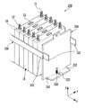
図1は、本発明の好ましい実施形態にかかるバッテリモジュールを示す図である。図2は、図1のバッテリモジュールの第1および第2エンドプレートと、サイドブラケットおよびボトムブラケットとを示す図である。 FIG. 1 is a diagram illustrating a battery module according to a preferred embodiment of the present invention. FIG. 2 is a diagram showing first and second end plates, side brackets and bottom brackets of the battery module of FIG. 1.
図1を参照すると、本発明の好ましい実施形態にかかるバッテリモジュール100は、対をなして対向配置される第1および第2エンドプレート110、120と、前記第1および第2エンドプレート110、120の間において一方向に配列された複数のバッテリセル10と、前記第1および第2エンドプレート110、120を連結する連結部材とを含む。
Referring to FIG. 1, a
前記連結部材は、ブラケットであってよく、前記ブラケットは、前記バッテリセル10の両側面を支持する側面連結部材であるサイドブラケット(bracket)130と、一端が前記第1エンドプレート110に結合され、前記バッテリセル10の底面を支持する底面連結部材であるボトムブラケット140とを含むことができる。
The connection member may be a bracket, and the bracket is coupled to a
バッテリセル10は、開口部を備える電池ケースと、前記開口部を密閉するキャッププレート14とを含む。前記電池ケースには、正極板および負極板と、これら極板の間に介在したセパレータとからなる電極アセンブリと、電解液とが収容される。また、前記キャッププレート14の両端には、正極板と連結される正極端子11と、負極板と連結される負極端子12とが外部に突出した形態で備えられる。前記正極板および負極板は、電解液と反応してエネルギーを発生し、このとき発生したエネルギーは、正極端子11および負極端子12を介して外部に伝達される。
The
また、キャッププレート14の正極端子11および負極端子12の間には、ベント13が備えられている。ベント13は、バッテリセル10の内部において気体の圧力が所定以上の場合に、前記気体を外部に放出する通路の役割を果たし、バッテリセル10が内圧により破損することを防止する。
A
本実施形態にかかるバッテリモジュール100は、第1および第2エンドプレート110、120の間に整列された複数のバッテリセル10を含むことができ、前記複数のバッテリセル10は、一方向に整列されて備えられてよい。このとき、バッテリセル10の広い全面が互いに対向するように並んで整列される。したがって、バッテリセル10のキャッププレート14の中心に備えられたベント13は、ほぼ一直線上に整列される。隣り合わせの2つのバッテリセル10の正極端子11および負極端子12は、ニッケルなどで形成されたバスバー(bus−bar)(図示せず)を介して電気的に連結可能である。
The
本実施形態では、前記バッテリセル10は、リチウムイオン二次電池として角形のものを例として説明する。ただし、本発明はこれに制限されるものではなく、本発明は、リチウムポリマー電池または円筒形電池などの多様な形態の電池を適用することができる。
In the present embodiment, the
バッテリモジュール100は、互いに空間的に離隔して備えられる一対の第1および第2エンドプレート110、120と、前記第1および第2エンドプレート110、120の左右側面を連結するサイドブラケット(braket)130と、前記第1および第2エンドプレート110、120の底面を連結するボトムブラケット140とを含むことができる。前記第1および第2エンドプレート110、120の間には、複数のバッテリセル10が整列されて配置される。
The
第1および第2エンドプレート110、120は、それぞれ最外郭のバッテリセル10と面接触するように配置され、複数のバッテリセル10を内側に加圧する。また、サイドブラケット130は、バッテリセル10の両側面を支持し、前記バッテリセル10の底面はボトムブラケット140により支持可能である。このとき、前記第1および第2エンドプレート110、120、サイドブラケット130およびボトムブラケット140により支持される複数のバッテリセル10は、その内部において正極端子11および負極端子12が互いに交互に整列され、直列に連結可能である。さらに、前記バッテリセル10の連結構造および個数は、バッテリモジュール100の設計に応じて多様に変形可能である。
The first and
第1エンドプレート110は、サイドブラケット130およびボトムブラケット140の一端と結合されて一体に形成可能である。具体的には、前記第1エンドプレート110の左側および右側にそれぞれ結合される2つのサイドブラケット130は、その一端131が第1エンドプレート110の左右側面とそれぞれ結合することで第1結合部151を形成することができる。また、前記ボトムブラケット140の一端141は、前記第1エンドプレート110の下部側と結合することで第2結合部152を形成することができる。前記第1および第2結合部151、152は、レーザ溶接または抵抗溶接などによって備えられてよい。
The
本実施形態において、第1エンドプレート110は、サイドブラケット130およびボトムブラケット140と結合させるために、別の部材を必要としない。したがって、ボルトまたはリベットなどを用いなくても、前記第1エンドプレート110と、サイドブラケット130およびボトムブラケット140の一端とを強固に結合させることが可能なため、生産段階が単純化され、同時に、ボルトなどの部材を省略することが可能なため、バッテリモジュール100を軽量化させることができる。
In the present embodiment, the
図2は、本発明の実施形態にかかる第1および第2エンドプレートと、サイドブラケットおよびボトムブラケットとを示す図である。 FIG. 2 is a view showing first and second end plates, a side bracket and a bottom bracket according to the embodiment of the present invention.
図2を参照して、前記第1および第2結合部151、152からなる結合部150について説明する。前記第1エンドプレート110は、第1および第2アラインマーク111、112を含むことができる。前記第1および第2アラインマーク111、112は、サイドブラケット130およびボトムブラケット140と、溶接などを用いて結合部150(図1参照)を形成する部分である。また、サイドブラケット130の第1端131およびボトムブラケット140の第1端141にはホール131a、141aが備えられ、前記ホール131a、141aは、第1および第2アラインマーク111、112に対応する部位に備えられることが好ましい。
With reference to FIG. 2, a
第1エンドプレート110においてサイドブラケット130が結合されるべき部分に予め第1アラインマーク111を具備させる。例えば、前記第1アラインマーク111は、突起の形態であってよく、前記突起は、サイドブラケット130の一端131に備えられるホールに挿入可能である。これと同様に、第2アラインマーク112は、例えば、突起の形態であってよい。前記第2アラインマーク112には、3つの突起112が備えられてよく、前記ボトムブラケット140の第1端141には、前記3つの突起112に対応する部分にそれぞれ3つのホール141aが備えられてよい。前記突起112は、それぞれ対応するホール141aに挿入され、前記ボトムブラケット140の位置をガイドすることができる。
A
このように、第1および第2アラインマーク111、112は、サイドブラケット130およびボトムブラケット140の付着する位置をガイドすることが可能なため、サイドブラケット130およびボトムブラケット140は、第1エンドプレート110の予め定めておいた位置に容易に付着させることができる。反面、前述したように、第1および第2アラインマーク111、112による結合は強固でなく、前記バッテリモジュール100に備えられる複数のバッテリセル10を支持するのに十分でない。したがって、前記突起が挿入された第1および第2アラインマーク111、112側には溶接をさらに含むことができ、前記溶接によって結合部150をさらに強固にすることができる。
Thus, since the first and second alignment marks 111 and 112 can guide the positions where the
また、前記第1および第2アラインマーク111、112と前記突起は、それに対応する位置に備えられればよいので、前記第1および第2アラインマーク111、112の個数および形状は、多様に変形可能である。 In addition, since the first and second alignment marks 111 and 112 and the protrusions need only be provided at the corresponding positions, the number and shape of the first and second alignment marks 111 and 112 can be variously modified. It is.
サイドブラケット130およびボトムブラケット140は、前記第2エンドプレート120と締結される結合部150が備えられ、z方向に沿って前記第1端131、141から離隔した第2端132、142を備えることができる。前記サイドブラケット130の第2端132は、延長部132であってよく、例えば、前記延長部132は、一方向(例えば、z方向)に配列された複数のバッテリセル10の側面よりもz方向により長くなるように、複数のバッテリセル10の側面を超えて延びることができる。
The
また、前記延長部132は、前記第2エンドプレート120の左右側面の縁で折曲げられたフランジ部121に対応して備えられてよい。これと同様に、前記ボトムブラケット140の第2端142は、延長部142であってよく、前記延長部142は、前記複数のバッテリセル10の底面よりもz方向により長くなるように、複数のバッテリセル10の底面を超えて延びることができる。前記ボトムブラケット140の延長部142は、第2エンドプレート120の底面の縁で折曲げられたフランジ部122に対応して備えられる。また、前記サイドブラケット130およびボトムブラケット140の延長部132、142は、第2エンドプレート120の左右側面および底面の縁で折曲げられたフランジ部121、122と、少なくとも一部にわたって互いに当接する面接触を形成することができる。
The
また、サイドブラケット130およびボトムブラケット140の延長部132、142には、それぞれホール132a、142aが備えられてよい。前記ホール132a、142aは、第2エンドプレート120のフランジ部121、122に備えられるホール121a、122aと、例えば、整列されるように対応する位置に備えられることが好ましい。前記サイドブラケット130およびボトムブラケット140の延長部132、142に備えられるホール132a、142aと、前記第2エンドプレート120のフランジ部121、122に備えられるホール121a、122aとは、互いに延びて1つの通路(channel)を形成することができ、前記通路は、例えば、リベットまたはボルトなどの締結具(fastener)160を収容するのに使用できる。このとき、サイドブラケット130およびボトムブラケット140と、第2エンドプレート120との締結をより強固にするために、前記締結具160で締結された部分に溶接をさらに含むことができる。
Further, the
別法として、サイドブラケット130およびボトムブラケット140の延長部132、142と、第2エンドプレート120のフランジ部121、122とにホールが備えられないこともある。この場合には、サイドブラケット130およびボトムブラケット140と第2エンドプレート120とを、溶接などを用いて締結させることができる。前述した溶接は、例えば、レーザ溶接または抵抗溶接などを用いて行われることが可能である。
Alternatively, the
前記サイドブラケット130およびボトムブラケット140の延長部132、142の形態は、第2エンドプレート120に備えられるフランジ部121、122に対応する形態で備えられることが好ましい。前記延長部132、142およびフランジ部121、122は締結され、サイドブラケット130およびボトムブラケット140を第2エンドプレート120に固定させればよいので、これに制限されるものではないが、前記延長部132、142およびフランジ部121、122が対応する形態で備えられると、前記バッテリモジュール100を設計に符合するように製作するガイドとなり得るため、生産性を向上させることができる。
The
また、サイドブラケット130は、支持部133をさらに含むことができる。前記支持部133は、サイドブラケット130の内側面に備えられ、バッテリセル10の左右側面を支持することができる。前記支持部133により、バッテリセル10は、前記第1および第2エンドプレート110、120の間でより強固に固定可能である。例えば、前記支持部133は、リブまたはビードの形態であってよく、前記バッテリセル10の側面に対応するように備えられてよい。
Further, the
図3A〜図4を参照して、本発明の他の実施形態にかかるバッテリモジュールを説明する。以下において、後述する内容を除けば、図1および図2で説明した内容と類似するため、これに関する詳細な内容は省略する。 A battery module according to another embodiment of the present invention will be described with reference to FIGS. 3A to 4. In the following, except for the contents to be described later, since it is similar to the contents described in FIG. 1 and FIG.
図3Aおよび図3Bは、本発明の好ましい実施形態にかかるバッテリモジュール200を示す図である。図3Aは、バッテリモジュール200において第2エンドプレート220を圧着させる前を示す図であり、図3Bは、第2エンドプレート220を圧着させた後を示す図である。
3A and 3B are diagrams showing a
図3Aおよび図3Bを参照すると、本実施形態にかかるバッテリモジュール200は、対をなして対向配置される第1エンドプレート(図示せず)および第2エンドプレート220と、前記第1および第2エンドプレート220の間において一方向に配列された複数のバッテリセル10と、前記第1および第2エンドプレート220に結合され、前記バッテリセル10の両側面を支持するサイドブラケット230と、一端が前記第1エンドプレートに結合され、前記バッテリセル10の底面を支持するボトムブラケット240とを含む。また、前記ボトムブラケット240の他端には、締結部材250が備えられてよく、前記第2エンドプレート220には、前記締結部材250に対応する位置にガイド部223が備えられてよい。
Referring to FIGS. 3A and 3B, a
図3Aおよび図3Bは、第1エンドプレート(図示せず)にサイドブラケット230およびボトムブラケット240が結合された状態において、複数のバッテリセル10を一方向に配列した後、前記バッテリセル10の最外郭には第2エンドプレート220を圧着させる様子を示した。
3A and 3B illustrate the outermost contour of the
本実施形態のボトムブラケット240は、締結部材250をさらに含むことができる。例えば、前記締結部材250は、ボトムブラケット240の延長部242に備えられるもので、例えば、スタッド(stud)であってよい。また、前記第2エンドプレート220は、ガイド部223をさらに含むことができる。前記ガイド部223は、第2エンドプレート220の底面と、フランジ部222とを経て形成されるように備えられてよい。前記フランジ部222は、第2エンドプレート220の底面の縁で折曲げられた部分であり、前記ボトムブラケット240の延長部242と、少なくとも一部が面接触するように備えられてよい。
The
ガイド部223は、例えば、ホールの形態であってよい。前記ガイド部223は、前記ボトムブラケット240に備えられた締結部材250に対応する形態で備えられてよい。すなわち、前記第2エンドプレート220を圧着させた後、これを固定するために、サイドブラケット230およびボトムブラケット240の延長部232、242を、第2エンドプレート220の左右側面および底面の縁から延びたフランジ部221、242と締結させる。このとき、前記第2エンドプレート220をサイドブラケット230およびボトムブラケット240に容易に締結固定させるために、前記第2エンドプレート220とボトムブラケット240とをまず締結させることが好ましい。
The
通常、前記第2エンドプレート220とボトムブラケット240とは、ボルト−ナットにより締結させる。このように、ボルト−ナットを用いる場合には、前記ボトムブラケット240の延長部242側は、その下部で挿入されるボルトのヘッドにより周辺部と段差づいた部分が生じ、中心を合わせにくくなることがある。
In general, the
これに対し、本発明では、ボトムブラケット240の延長部242にスタッドなどの締結部材250が備えられる。前記スタッドは、ボトムブラケット240の延長部242に挿入して製作できるため、別のボルトを必要とせず、また、前述したボルトのヘッド部によってもたらされる、段差づいた部分が生じない。
In contrast, in the present invention, the
また、第2エンドプレート220には、前記ボトムブラケット240に備えられた締結部材250に対応する位置にガイド部223を含むことができる。前記ガイド部223は、第2エンドプレート220を用いてバッテリセル10を圧着するとき、その位置をガイドする役割を果たす部分であり、前記バッテリモジュール200の組立を容易にする。
The
さらに、前記バッテリモジュール200は、固定部材260を含むことができる。前記固定部材260は、前記ボトムブラケット240の締結部材250が通過するホールを含む。前記固定部材260は、前記締結部材250と結合した後、前記サイドブラケット230の延長部232と前記第2エンドプレート220のフランジ部221とを、例えば、溶接(weld)251によって結合させることができる。
Further, the
図4は、図3BのA−A断面図である。 4 is a cross-sectional view taken along line AA in FIG. 3B.
図4を参照すると、前記ガイド部223は、第2エンドプレート220でバッテリセル10を圧着するとき、ボトムブラケット240に備えられる締結部材250との干渉を防止するために備えられてよい。前記ガイド部223は、第2エンドプレート220の底部を経てフランジ部222に延びて形成可能である。
Referring to FIG. 4, the
このとき、第2エンドプレート220の底部に備えられるガイド部223の形態は、ボトムブラケット240に備えられた締結部材250の高さ方向の断面に対応して備えられてよい。また、前記フランジ部222に備えられるガイド部223は、前記締結部材250の横方向の断面に対応して備えられてよい。
At this time, the form of the
前記フランジ部222に備えられるガイド部223の形態は、テーパ型(tapertype)であることが好ましい。前記フランジ部222側のガイド部223は、第2エンドプレート220の底面の縁で次第に幅が細くなる形態で備えられてよく、このとき、前記テーパ型の最も狭い幅は、締結部材250の横方向の断面に対応するように備えられてよい。このように、テーパ型で備えられるフランジ部222側のガイド部223は、第2エンドプレート220を圧着するとき、左右側の組立公差を防ぐガイドの役割を果たし、バッテリモジュール200の組立を容易にし、生産性を向上させる。
The shape of the
また、本発明のバッテリモジュール200は、固定部材260をさらに含むことができる。固定部材260には、ボトムブラケット240に備えられる締結部材250が貫通可能なホールを備える。本実施形態にかかるバッテリモジュール200は、ガイド部223を介して突出した締結部材250を、前記固定部材260に備えられたホールを貫通させることにより、第2エンドプレート220とボトムブラケット240との結合を強固にすることができる。例えば、前記固定部材260は、ナットなどを用いることができる。
In addition, the
以上、添付図面を参照しながら本発明の好適な実施形態について詳細に説明したが、本発明はかかる例に限定されない。本発明の属する技術の分野における通常の知識を有する者であれば、特許請求の範囲に記載された技術的思想の範疇内において、各種の変更例または修正例に想到し得ることは明らかであり、これらについても、当然に本発明の技術的範囲に属するものと了解される。 The preferred embodiments of the present invention have been described in detail above with reference to the accompanying drawings, but the present invention is not limited to such examples. It is obvious that a person having ordinary knowledge in the technical field to which the present invention pertains can come up with various changes or modifications within the scope of the technical idea described in the claims. Of course, it is understood that these also belong to the technical scope of the present invention.
10:バッテリセル
11:正極端子
12:負極端子
13:ベント
14:キャッププレート
100、200:バッテリモジュール
110:第1エンドプレート
111、112:第1および第2アラインマーク
120、220:第2エンドプレート
130、230:サイドブラケット
131:支持部
140、240:ボトムブラケット
150、151、151:結合部
223:ガイド部
250:結合部材
260:固定部材
10: Battery cell 11: Positive terminal 12: Negative terminal 13: Vent 14:
Claims (20)
前記複数のバッテリセルの第1最外郭バッテリセルに隣接する第1エンドプレートと、前記複数のバッテリセルの第2最外郭バッテリセルに隣接し、前記第1方向に沿って前記第1エンドプレートから離隔して備えられる第2エンドプレートと、
前記複数のバッテリセルに沿って前記第1方向に延び、前記第1エンドプレートと連結される第1端、および第2エンドプレートと連結される第2端を備える連結部材と、
前記連結部材の第1端を前記第1エンドプレートに結合させる第1結合部と、
前記第2端を第2エンドプレートに結合させ、前記第1結合部とは異なる形態を有する第2結合部と、を含むことを特徴とする、バッテリモジュール。 A plurality of battery cells aligned in a first direction;
A first end plate adjacent to the first outermost battery cell of the plurality of battery cells; a second end plate adjacent to the second outermost battery cell of the plurality of battery cells; and from the first end plate along the first direction. A second end plate provided at a distance;
A connecting member that extends in the first direction along the plurality of battery cells and includes a first end connected to the first end plate and a second end connected to the second end plate;
A first coupling portion coupling the first end of the coupling member to the first end plate;
A battery module, comprising: a second coupling part that couples the second end to a second end plate and has a form different from that of the first coupling part.
The battery module according to claim 19, further comprising a fixing member that fixes the fastening member.
Applications Claiming Priority (4)
| Application Number | Priority Date | Filing Date | Title |
|---|---|---|---|
| US201161445765P | 2011-02-23 | 2011-02-23 | |
| US61/445765 | 2011-02-23 | ||
| US13/304918 | 2011-11-28 | ||
| US13/304,918 US8771864B2 (en) | 2011-02-23 | 2011-11-28 | Battery module |
Publications (2)
| Publication Number | Publication Date |
|---|---|
| JP2012174693A true JP2012174693A (en) | 2012-09-10 |
| JP6071213B2 JP6071213B2 (en) | 2017-02-01 |
Family
ID=45656237
Family Applications (1)
| Application Number | Title | Priority Date | Filing Date |
|---|---|---|---|
| JP2012036725A Active JP6071213B2 (en) | 2011-02-23 | 2012-02-22 | Battery module |
Country Status (5)
| Country | Link |
|---|---|
| US (1) | US8771864B2 (en) |
| EP (1) | EP2492990B1 (en) |
| JP (1) | JP6071213B2 (en) |
| KR (1) | KR20120096886A (en) |
| CN (1) | CN102651462B (en) |
Cited By (10)
| Publication number | Priority date | Publication date | Assignee | Title |
|---|---|---|---|---|
| EP2790242A2 (en) | 2013-04-08 | 2014-10-15 | GS Yuasa International Ltd. | Battery module |
| JP2015043293A (en) * | 2013-08-26 | 2015-03-05 | 株式会社Gsユアサ | Power storage device and method of manufacturing the same |
| JP2015099649A (en) * | 2013-11-18 | 2015-05-28 | 本田技研工業株式会社 | Power storage module |
| JP2015170510A (en) * | 2014-03-07 | 2015-09-28 | 株式会社豊田自動織機 | battery pack |
| WO2015152637A1 (en) * | 2014-04-03 | 2015-10-08 | 주식회사 엘지화학 | Battery pack comprising tension bar |
| WO2015152638A1 (en) * | 2014-04-03 | 2015-10-08 | 주식회사 엘지화학 | Battery module array comprising under-base bar |
| JP2016035906A (en) * | 2014-07-31 | 2016-03-17 | 株式会社Gsユアサ | Power source module |
| JP2016048634A (en) * | 2014-08-27 | 2016-04-07 | 株式会社Gsユアサ | Power storage device, and manufacturing method of power storage device |
| JP2017016799A (en) * | 2015-06-29 | 2017-01-19 | 株式会社Gsユアサ | Power storage device |
| JP2019512153A (en) * | 2016-02-25 | 2019-05-09 | バイエリシエ・モトーレンウエルケ・アクチエンゲゼルシヤフト | Cell module for a vehicle battery and method of manufacturing such a cell module |
Families Citing this family (18)
| Publication number | Priority date | Publication date | Assignee | Title |
|---|---|---|---|---|
| KR101117686B1 (en) * | 2009-12-28 | 2012-02-29 | 에스비리모티브 주식회사 | Battery module and battery pack having the same |
| KR101383629B1 (en) * | 2012-03-14 | 2014-04-14 | 주식회사 엘지화학 | Battery Cell Havig Through Hole and Battery Pack Comprising The Same |
| KR101999405B1 (en) | 2013-02-05 | 2019-07-11 | 삼성에스디아이 주식회사 | Battery pack and method for manufacturing the same |
| KR101814735B1 (en) * | 2013-05-29 | 2018-01-03 | 삼성에스디아이 주식회사 | Battery module |
| KR20140140791A (en) * | 2013-05-30 | 2014-12-10 | 삼성에스디아이 주식회사 | Battery module |
| KR101708365B1 (en) * | 2013-09-13 | 2017-02-20 | 삼성에스디아이 주식회사 | Battery pack |
| DE102014215543A1 (en) * | 2014-08-06 | 2016-02-11 | Robert Bosch Gmbh | Frame device for receiving memory cells of an energy storage module |
| US9911951B2 (en) | 2014-09-30 | 2018-03-06 | Johnson Controls Technology Company | Battery module compressed cell assembly |
| KR101805652B1 (en) | 2015-08-28 | 2017-12-06 | 삼성에스디아이 주식회사 | Rechargeable battery pack |
| KR101805650B1 (en) * | 2015-08-28 | 2017-12-06 | 삼성에스디아이 주식회사 | Rechargeable battery pack |
| KR102019884B1 (en) * | 2015-11-13 | 2019-09-09 | 주식회사 엘지화학 | Battery module, battery pack comprising the battery module and vehicle comprising the battery pack |
| KR102092268B1 (en) * | 2015-11-30 | 2020-03-23 | 주식회사 엘지화학 | Clamping member and battery module using thereof |
| KR102178959B1 (en) | 2017-04-06 | 2020-11-13 | 주식회사 엘지화학 | End plate, battery module, battery pack comprising the battery module and vehicle comprising the battery pack |
| JP6447694B2 (en) * | 2017-09-27 | 2019-01-09 | 株式会社豊田自動織機 | Battery module |
| KR102353921B1 (en) * | 2018-01-12 | 2022-01-20 | 주식회사 엘지에너지솔루션 | Battery module, battery pack and vehicle comprising the same |
| KR20210133543A (en) * | 2020-04-29 | 2021-11-08 | 주식회사 엘지에너지솔루션 | Battery module and battery pack including the same |
| KR20230007739A (en) * | 2021-07-06 | 2023-01-13 | 주식회사 엘지에너지솔루션 | Battery module and battery pack including the same |
| CN114639909B (en) * | 2022-03-29 | 2024-04-19 | 远景动力技术(江苏)有限公司 | Shell of battery pack and manufacturing method thereof |
Citations (3)
| Publication number | Priority date | Publication date | Assignee | Title |
|---|---|---|---|---|
| JP2001068081A (en) * | 1999-08-31 | 2001-03-16 | Matsushita Electric Ind Co Ltd | Set battery |
| JP2008282582A (en) * | 2007-05-08 | 2008-11-20 | Sanyo Electric Co Ltd | Battery pack |
| JP2010092610A (en) * | 2008-10-03 | 2010-04-22 | Toyota Motor Corp | Battery pack structure, vehicle, battery mounting equipment, and method for manufacturing battery pack structure |
Family Cites Families (11)
| Publication number | Priority date | Publication date | Assignee | Title |
|---|---|---|---|---|
| US5409787A (en) * | 1993-02-17 | 1995-04-25 | Electrosource, Inc. | Battery plate compression cage assembly |
| US5789091C1 (en) | 1996-11-19 | 2001-02-27 | Ballard Power Systems | Electrochemical fuel cell stack with compression bands |
| KR100232626B1 (en) | 1997-08-27 | 1999-12-01 | 정몽규 | Unification structure of a battery module for an electric car |
| US6218039B1 (en) | 1999-08-25 | 2001-04-17 | Plug Power, Inc. | Clamping apparatus and method for a fuel cell |
| KR100669333B1 (en) | 2005-01-25 | 2007-01-15 | 삼성에스디아이 주식회사 | Secondary battery module |
| KR100821442B1 (en) * | 2005-05-31 | 2008-04-10 | 마쯔시다덴기산교 가부시키가이샤 | Non-aqueous electrolyte secondary battery and battery module |
| KR100646954B1 (en) | 2005-10-07 | 2006-11-23 | 삼성에스디아이 주식회사 | Apparatus to detect cell voltage of fuel cell stack and fuel cell system using the same |
| US7807316B2 (en) | 2006-11-01 | 2010-10-05 | Gm Global Technology Operations, Inc. | Fuel cell stack compression retention system with external springs |
| US8465881B2 (en) | 2007-12-20 | 2013-06-18 | Daimler Ag | Compression apparatus for fuel cell stack |
| CN102037597A (en) | 2008-05-19 | 2011-04-27 | 松下电器产业株式会社 | Fuel cell and method for diassembling the same |
| KR101199217B1 (en) * | 2010-11-11 | 2012-11-07 | 에스비리모티브 주식회사 | Battery module |
-
2011
- 2011-11-28 US US13/304,918 patent/US8771864B2/en active Active
- 2011-12-28 CN CN201110448015.0A patent/CN102651462B/en active Active
-
2012
- 2012-02-03 KR KR1020120011167A patent/KR20120096886A/en not_active Application Discontinuation
- 2012-02-20 EP EP12156264.9A patent/EP2492990B1/en active Active
- 2012-02-22 JP JP2012036725A patent/JP6071213B2/en active Active
Patent Citations (3)
| Publication number | Priority date | Publication date | Assignee | Title |
|---|---|---|---|---|
| JP2001068081A (en) * | 1999-08-31 | 2001-03-16 | Matsushita Electric Ind Co Ltd | Set battery |
| JP2008282582A (en) * | 2007-05-08 | 2008-11-20 | Sanyo Electric Co Ltd | Battery pack |
| JP2010092610A (en) * | 2008-10-03 | 2010-04-22 | Toyota Motor Corp | Battery pack structure, vehicle, battery mounting equipment, and method for manufacturing battery pack structure |
Cited By (18)
| Publication number | Priority date | Publication date | Assignee | Title |
|---|---|---|---|---|
| US9337460B2 (en) | 2013-04-08 | 2016-05-10 | Gs Yuasa International Ltd. | Battery module |
| KR20140121767A (en) | 2013-04-08 | 2014-10-16 | 가부시키가이샤 지에스 유아사 | Battery module |
| EP2790242A2 (en) | 2013-04-08 | 2014-10-15 | GS Yuasa International Ltd. | Battery module |
| JP2015043293A (en) * | 2013-08-26 | 2015-03-05 | 株式会社Gsユアサ | Power storage device and method of manufacturing the same |
| JP2015099649A (en) * | 2013-11-18 | 2015-05-28 | 本田技研工業株式会社 | Power storage module |
| JP2015170510A (en) * | 2014-03-07 | 2015-09-28 | 株式会社豊田自動織機 | battery pack |
| US10056601B2 (en) | 2014-03-07 | 2018-08-21 | Kabushiki Kaisha Toyota Jidoshokki | Battery pack |
| KR101807115B1 (en) * | 2014-04-03 | 2017-12-08 | 주식회사 엘지화학 | Battery module array having under base bar |
| US9583748B2 (en) | 2014-04-03 | 2017-02-28 | Lg Chem, Ltd. | Battery pack having tension bar |
| WO2015152638A1 (en) * | 2014-04-03 | 2015-10-08 | 주식회사 엘지화학 | Battery module array comprising under-base bar |
| US9978998B2 (en) | 2014-04-03 | 2018-05-22 | Lg Chem, Ltd. | Battery module array comprising under-base bar |
| WO2015152637A1 (en) * | 2014-04-03 | 2015-10-08 | 주식회사 엘지화학 | Battery pack comprising tension bar |
| JP2016035906A (en) * | 2014-07-31 | 2016-03-17 | 株式会社Gsユアサ | Power source module |
| US9947958B2 (en) | 2014-07-31 | 2018-04-17 | Gs Yuasa International Ltd. | Power source module |
| JP2016048634A (en) * | 2014-08-27 | 2016-04-07 | 株式会社Gsユアサ | Power storage device, and manufacturing method of power storage device |
| JP2017016799A (en) * | 2015-06-29 | 2017-01-19 | 株式会社Gsユアサ | Power storage device |
| JP2019512153A (en) * | 2016-02-25 | 2019-05-09 | バイエリシエ・モトーレンウエルケ・アクチエンゲゼルシヤフト | Cell module for a vehicle battery and method of manufacturing such a cell module |
| US10727461B2 (en) | 2016-02-25 | 2020-07-28 | Bayerische Motoren Werke Aktiengesellschaft | Cell module for a battery of a motor vehicle and method for producing such a cell module |
Also Published As
| Publication number | Publication date |
|---|---|
| US20120214046A1 (en) | 2012-08-23 |
| KR20120096886A (en) | 2012-08-31 |
| US8771864B2 (en) | 2014-07-08 |
| CN102651462B (en) | 2016-08-24 |
| CN102651462A (en) | 2012-08-29 |
| EP2492990A1 (en) | 2012-08-29 |
| EP2492990B1 (en) | 2016-11-23 |
| JP6071213B2 (en) | 2017-02-01 |
Similar Documents
| Publication | Publication Date | Title |
|---|---|---|
| JP6071213B2 (en) | Battery module | |
| JP5908706B2 (en) | Battery module | |
| KR101252952B1 (en) | Battery module for preventing movement of battery cell | |
| JP6088185B2 (en) | Battery module | |
| JP5323782B2 (en) | Battery module and battery pack comprising a plurality of battery modules | |
| KR100891079B1 (en) | Battery Cartridge-connecting System For Battery Module | |
| EP2648243B1 (en) | Battery module | |
| KR100599732B1 (en) | Secondary battery | |
| US20140045038A1 (en) | Assembled battery and vehicle | |
| US9012063B2 (en) | Battery module | |
| US8999545B2 (en) | Battery module | |
| KR101683209B1 (en) | Rechargeable battery | |
| EP2521203B1 (en) | Battery module | |
| KR20100081508A (en) | Battery module | |
| KR20170021529A (en) | Battery pack | |
| KR100627360B1 (en) | Plate used to collect current, secondary battery and module thereof | |
| JP2011514636A (en) | Medium or large battery module having electrode terminal connecting member and insulating bonding member | |
| CN104167515A (en) | Cap plate and battery | |
| EP2797138A1 (en) | Battery pack | |
| KR101275487B1 (en) | Battery unit cell comprised in inserted case and battery module assembled at least one thereof | |
| EP2490277A1 (en) | Battery Module | |
| CN210403845U (en) | Battery module, battery pack and vehicle | |
| KR101822879B1 (en) | Secondary battery module | |
| JP2011129310A (en) | Battery module | |
| KR100627296B1 (en) | Secondary battery and terminal assembly using the same |
Legal Events
| Date | Code | Title | Description |
|---|---|---|---|
| A711 | Notification of change in applicant |
Free format text: JAPANESE INTERMEDIATE CODE: A711 Effective date: 20121226 |
|
| A621 | Written request for application examination |
Free format text: JAPANESE INTERMEDIATE CODE: A621 Effective date: 20150122 |
|
| A977 | Report on retrieval |
Free format text: JAPANESE INTERMEDIATE CODE: A971007 Effective date: 20151224 |
|
| A131 | Notification of reasons for refusal |
Free format text: JAPANESE INTERMEDIATE CODE: A131 Effective date: 20160126 |
|
| A521 | Request for written amendment filed |
Free format text: JAPANESE INTERMEDIATE CODE: A523 Effective date: 20160426 |
|
| A131 | Notification of reasons for refusal |
Free format text: JAPANESE INTERMEDIATE CODE: A131 Effective date: 20160802 |
|
| A521 | Request for written amendment filed |
Free format text: JAPANESE INTERMEDIATE CODE: A523 Effective date: 20161102 |
|
| TRDD | Decision of grant or rejection written | ||
| A01 | Written decision to grant a patent or to grant a registration (utility model) |
Free format text: JAPANESE INTERMEDIATE CODE: A01 Effective date: 20161220 |
|
| A61 | First payment of annual fees (during grant procedure) |
Free format text: JAPANESE INTERMEDIATE CODE: A61 Effective date: 20161227 |
|
| R150 | Certificate of patent or registration of utility model |
Ref document number: 6071213 Country of ref document: JP Free format text: JAPANESE INTERMEDIATE CODE: R150 |
|
| R250 | Receipt of annual fees |
Free format text: JAPANESE INTERMEDIATE CODE: R250 |
|
| R250 | Receipt of annual fees |
Free format text: JAPANESE INTERMEDIATE CODE: R250 |
|
| R250 | Receipt of annual fees |
Free format text: JAPANESE INTERMEDIATE CODE: R250 |
|
| R250 | Receipt of annual fees |
Free format text: JAPANESE INTERMEDIATE CODE: R250 |
|
| R250 | Receipt of annual fees |
Free format text: JAPANESE INTERMEDIATE CODE: R250 |