EP4297149A1 - Busbar assembly - Google Patents
Busbar assembly Download PDFInfo
- Publication number
- EP4297149A1 EP4297149A1 EP22180156.6A EP22180156A EP4297149A1 EP 4297149 A1 EP4297149 A1 EP 4297149A1 EP 22180156 A EP22180156 A EP 22180156A EP 4297149 A1 EP4297149 A1 EP 4297149A1
- Authority
- EP
- European Patent Office
- Prior art keywords
- busbar
- busbar assembly
- cavity
- assembly
- section
- Prior art date
- Legal status (The legal status is an assumption and is not a legal conclusion. Google has not performed a legal analysis and makes no representation as to the accuracy of the status listed.)
- Pending
Links
- 239000004020 conductor Substances 0.000 claims abstract description 10
- 238000009826 distribution Methods 0.000 claims abstract description 8
- 238000001816 cooling Methods 0.000 claims abstract description 6
- 230000000712 assembly Effects 0.000 description 6
- 238000000429 assembly Methods 0.000 description 6
- 230000003247 decreasing effect Effects 0.000 description 2
- 238000004519 manufacturing process Methods 0.000 description 2
- 239000000463 material Substances 0.000 description 2
- 238000010292 electrical insulation Methods 0.000 description 1
- 230000005611 electricity Effects 0.000 description 1
- 230000005520 electrodynamics Effects 0.000 description 1
- 238000009434 installation Methods 0.000 description 1
- 239000002184 metal Substances 0.000 description 1
- 238000000034 method Methods 0.000 description 1
- 238000013021 overheating Methods 0.000 description 1
- 238000003860 storage Methods 0.000 description 1
Images


Classifications
-
- H—ELECTRICITY
- H01—ELECTRIC ELEMENTS
- H01M—PROCESSES OR MEANS, e.g. BATTERIES, FOR THE DIRECT CONVERSION OF CHEMICAL ENERGY INTO ELECTRICAL ENERGY
- H01M10/00—Secondary cells; Manufacture thereof
- H01M10/60—Heating or cooling; Temperature control
- H01M10/61—Types of temperature control
- H01M10/613—Cooling or keeping cold
-
- H—ELECTRICITY
- H01—ELECTRIC ELEMENTS
- H01M—PROCESSES OR MEANS, e.g. BATTERIES, FOR THE DIRECT CONVERSION OF CHEMICAL ENERGY INTO ELECTRICAL ENERGY
- H01M10/00—Secondary cells; Manufacture thereof
- H01M10/60—Heating or cooling; Temperature control
- H01M10/62—Heating or cooling; Temperature control specially adapted for specific applications
- H01M10/625—Vehicles
-
- H—ELECTRICITY
- H01—ELECTRIC ELEMENTS
- H01M—PROCESSES OR MEANS, e.g. BATTERIES, FOR THE DIRECT CONVERSION OF CHEMICAL ENERGY INTO ELECTRICAL ENERGY
- H01M10/00—Secondary cells; Manufacture thereof
- H01M10/60—Heating or cooling; Temperature control
- H01M10/64—Heating or cooling; Temperature control characterised by the shape of the cells
- H01M10/647—Prismatic or flat cells, e.g. pouch cells
-
- H—ELECTRICITY
- H01—ELECTRIC ELEMENTS
- H01M—PROCESSES OR MEANS, e.g. BATTERIES, FOR THE DIRECT CONVERSION OF CHEMICAL ENERGY INTO ELECTRICAL ENERGY
- H01M10/00—Secondary cells; Manufacture thereof
- H01M10/60—Heating or cooling; Temperature control
- H01M10/65—Means for temperature control structurally associated with the cells
- H01M10/653—Means for temperature control structurally associated with the cells characterised by electrically insulating or thermally conductive materials
-
- H—ELECTRICITY
- H01—ELECTRIC ELEMENTS
- H01M—PROCESSES OR MEANS, e.g. BATTERIES, FOR THE DIRECT CONVERSION OF CHEMICAL ENERGY INTO ELECTRICAL ENERGY
- H01M10/00—Secondary cells; Manufacture thereof
- H01M10/60—Heating or cooling; Temperature control
- H01M10/65—Means for temperature control structurally associated with the cells
- H01M10/655—Solid structures for heat exchange or heat conduction
- H01M10/6551—Surfaces specially adapted for heat dissipation or radiation, e.g. fins or coatings
-
- H—ELECTRICITY
- H01—ELECTRIC ELEMENTS
- H01M—PROCESSES OR MEANS, e.g. BATTERIES, FOR THE DIRECT CONVERSION OF CHEMICAL ENERGY INTO ELECTRICAL ENERGY
- H01M10/00—Secondary cells; Manufacture thereof
- H01M10/60—Heating or cooling; Temperature control
- H01M10/65—Means for temperature control structurally associated with the cells
- H01M10/655—Solid structures for heat exchange or heat conduction
- H01M10/6553—Terminals or leads
-
- H—ELECTRICITY
- H01—ELECTRIC ELEMENTS
- H01M—PROCESSES OR MEANS, e.g. BATTERIES, FOR THE DIRECT CONVERSION OF CHEMICAL ENERGY INTO ELECTRICAL ENERGY
- H01M50/00—Constructional details or processes of manufacture of the non-active parts of electrochemical cells other than fuel cells, e.g. hybrid cells
- H01M50/50—Current conducting connections for cells or batteries
- H01M50/502—Interconnectors for connecting terminals of adjacent batteries; Interconnectors for connecting cells outside a battery casing
- H01M50/503—Interconnectors for connecting terminals of adjacent batteries; Interconnectors for connecting cells outside a battery casing characterised by the shape of the interconnectors
-
- H—ELECTRICITY
- H01—ELECTRIC ELEMENTS
- H01M—PROCESSES OR MEANS, e.g. BATTERIES, FOR THE DIRECT CONVERSION OF CHEMICAL ENERGY INTO ELECTRICAL ENERGY
- H01M50/00—Constructional details or processes of manufacture of the non-active parts of electrochemical cells other than fuel cells, e.g. hybrid cells
- H01M50/50—Current conducting connections for cells or batteries
- H01M50/502—Interconnectors for connecting terminals of adjacent batteries; Interconnectors for connecting cells outside a battery casing
- H01M50/505—Interconnectors for connecting terminals of adjacent batteries; Interconnectors for connecting cells outside a battery casing comprising a single busbar
-
- H—ELECTRICITY
- H01—ELECTRIC ELEMENTS
- H01M—PROCESSES OR MEANS, e.g. BATTERIES, FOR THE DIRECT CONVERSION OF CHEMICAL ENERGY INTO ELECTRICAL ENERGY
- H01M50/00—Constructional details or processes of manufacture of the non-active parts of electrochemical cells other than fuel cells, e.g. hybrid cells
- H01M50/50—Current conducting connections for cells or batteries
- H01M50/502—Interconnectors for connecting terminals of adjacent batteries; Interconnectors for connecting cells outside a battery casing
- H01M50/521—Interconnectors for connecting terminals of adjacent batteries; Interconnectors for connecting cells outside a battery casing characterised by the material
- H01M50/522—Inorganic material
-
- H—ELECTRICITY
- H01—ELECTRIC ELEMENTS
- H01M—PROCESSES OR MEANS, e.g. BATTERIES, FOR THE DIRECT CONVERSION OF CHEMICAL ENERGY INTO ELECTRICAL ENERGY
- H01M50/00—Constructional details or processes of manufacture of the non-active parts of electrochemical cells other than fuel cells, e.g. hybrid cells
- H01M50/50—Current conducting connections for cells or batteries
- H01M50/502—Interconnectors for connecting terminals of adjacent batteries; Interconnectors for connecting cells outside a battery casing
- H01M50/521—Interconnectors for connecting terminals of adjacent batteries; Interconnectors for connecting cells outside a battery casing characterised by the material
- H01M50/524—Organic material
-
- H—ELECTRICITY
- H01—ELECTRIC ELEMENTS
- H01M—PROCESSES OR MEANS, e.g. BATTERIES, FOR THE DIRECT CONVERSION OF CHEMICAL ENERGY INTO ELECTRICAL ENERGY
- H01M50/00—Constructional details or processes of manufacture of the non-active parts of electrochemical cells other than fuel cells, e.g. hybrid cells
- H01M50/50—Current conducting connections for cells or batteries
- H01M50/502—Interconnectors for connecting terminals of adjacent batteries; Interconnectors for connecting cells outside a battery casing
- H01M50/521—Interconnectors for connecting terminals of adjacent batteries; Interconnectors for connecting cells outside a battery casing characterised by the material
- H01M50/526—Interconnectors for connecting terminals of adjacent batteries; Interconnectors for connecting cells outside a battery casing characterised by the material having a layered structure
-
- H—ELECTRICITY
- H01—ELECTRIC ELEMENTS
- H01M—PROCESSES OR MEANS, e.g. BATTERIES, FOR THE DIRECT CONVERSION OF CHEMICAL ENERGY INTO ELECTRICAL ENERGY
- H01M2220/00—Batteries for particular applications
- H01M2220/20—Batteries in motive systems, e.g. vehicle, ship, plane
-
- Y—GENERAL TAGGING OF NEW TECHNOLOGICAL DEVELOPMENTS; GENERAL TAGGING OF CROSS-SECTIONAL TECHNOLOGIES SPANNING OVER SEVERAL SECTIONS OF THE IPC; TECHNICAL SUBJECTS COVERED BY FORMER USPC CROSS-REFERENCE ART COLLECTIONS [XRACs] AND DIGESTS
- Y02—TECHNOLOGIES OR APPLICATIONS FOR MITIGATION OR ADAPTATION AGAINST CLIMATE CHANGE
- Y02E—REDUCTION OF GREENHOUSE GAS [GHG] EMISSIONS, RELATED TO ENERGY GENERATION, TRANSMISSION OR DISTRIBUTION
- Y02E60/00—Enabling technologies; Technologies with a potential or indirect contribution to GHG emissions mitigation
- Y02E60/10—Energy storage using batteries
Definitions
- the present invention relates to a busbar assembly for electrical power distribution in an electric vehicle.
- the field of the invention is more particularly that of hybrid or electric vehicles in which the energy is stored in a storage battery.
- a busbar is a metal strip or bar that conducts electricity and is used for electrical power distribution. Electrical distribution equipment, including switchboards, switchgears, and motor control centers, use busbar conductors to connect circuit breakers and other protection equipment to loads.
- Car battery cells can be connected with busbars to make for instance battery modules and battery packs.
- a power supply for an electric vehicle such as a hybrid car or an electric car requires a large power output.
- the flow of electric current to and from the individual cells is such that when several such cells are combined into successively larger assemblies (such as modules and packs), the current or voltage can be increased to generate the desired power output.
- larger module and pack assemblies are made up of one or more cells joined in series (for increased voltage), parallel (for increased battery capacity) or both, and may include additional structure to ensure proper installation and operation of these cells.
- the battery cells disposed adjacently to each other are electrically connected to each other by busbars each made of a conductive material.
- the busbar made of a conductive material is stacked via a connector on electrode terminals (or electrode lead) of the battery cells, and stacked portions of the busbar are welded to the electrode terminals of the battery cells.
- the battery cells can be connected to each other with small electric resistance.
- the increase in the number of cells may additionally increase a risk of the battery overheating due to heat generated by a cell.
- busbars it is thus important for the busbars to have a structure which on the one hand ensures the rigidity required to withstand the electrodynamic stresses produced by the flow of current during normal conduction and on the other hand allows to optimize the heat flow.
- Busbars assembly comprising busbars having different shapes are known from the prior art.
- bus system for use in electrical distribution equipment.
- the bus system comprises a busbar comprising a pair of oppositely facing bowl-shaped conductors, forming an octagonal cross section in which air gaps are formed.
- the air gap increases cooling efficiency by natural convection by exposing more surface area of the conductors directly to the air flow.
- EP1131868A1 discloses a busbar having a C-shaped cross-section.
- the C-shaped cross-section allows a modular geometry.
- the present disclosure is designed to solve the problems mentioned above. Accordingly, the present invention provides, the present disclosure is directed to a busbar assembly for an electric vehicle according to claim 1.
- the busbar assembly has a busbar for electric power distribution and a connector.
- the busbar comprises a body made of conducting material, the body being at least partially hollow, such that the busbar comprises at least one inner conductive surface and an air gap adapted to increase cooling efficiency by natural convection.
- the connector is arranged on and/or connected to the inner conductive surface of the busbar and the outer surface of the busbar is electrically insulated.
- Such designs allows to decrease the size of the busbar without decreasing the performance.
- the contact area being on the inner surface of the busbar body, the conductive surface is increased.
- the hollow configuration increases the heat transfer to the environment. The amount of material used in production is reduced, so as to achieve both an economic benefit and a lighter assembly.
- the connections are inside the busbar; the busbar remains touch-safe on its outer surface and is adapted to keep an electrical insulation, even in the case of fire.
- the body extend longitudinally along a longitudinal axis X between a first end and a second end and has a body length L, wherein the body comprises a cavity extending longitudinally through the body from the first end to the second end. The cavity is thus through the body and the conductive surface is increased as well as the air gap for natural convection.
- the body is integral.
- the body is made of one part and no junction are formed.
- the cavity has a substantially circular or quadrangular or triangular transverse cross-section.
- the body comprises a lateral aperture connected to the cavity.
- the lateral aperture increases the natural air convection. Air can freely flow between the gaps and will not get trapped inside the cavity.
- the lateral aperture allows the natural air convection inside cavity.
- the lateral aperture extend longitudinally over a portion of the body length L.
- the lateral aperture is formed by several holes.
- the lateral aperture may have other shapes.
- the cavity is a first cavity and the body comprises a second cavity.
- This increases the connecting surfaces without increasing the length of the busbar body.
- two air gaps are thus arranged to increase the natural convection by exposing more surface area of the conductors directly to the air flow.
- the two air gaps for instance communicate with each other.
- the second cavity longitudinally extends through the body from the first end to the second end.
- the first and second cavity may each have an annular cross-section. For instance they can be concentrically arranged around the longitudinal axis.
- the body has a substantially circular or quadrangular or triangular transverse cross-section. These shapes allow to easily manufacture an integral body (a body in one part, without junction) with a cavity.
- the present invention is also directed to a battery system comprising at least one battery cell and a busbar assembly according to any of the preceding claims, wherein the connector connects an electrode lead of the at least one battery cell to the busbar body.
- Fig. 1 illustrates a portion of an exemplary battery system 10.
- the battery system 10 comprises a first battery component 12 and a second battery component 14.
- the battery components 12, 14 are connected in parallel. However, in other embodiments, several battery components may be provided, connected in parallel or in series or both.
- Busbar assemblies 16 are used to connect the battery components in this parallel arrangement.
- a first and a second busbar assembly 16 are depicted in Fig. 1 .
- Each busbar assembly 16 is coupled to the battery components 12, 14.
- Battery components 12, 14 can be battery cells, battery modules, battery packs or any battery sub-assembly.
- the busbar assembly 16 comprises a busbar 18 for electric power distribution and a connector 20.
- the connector electrically connects the busbar 18 to a battery component 12, 14.
- the busbar 18 comprises a body made of conducting material.
- the body longitudinally extend along a longitudinal axis X and has a body length L.
- the body is at least partially hollow and comprises an inner surface 22 and an outer surface 24.
- the hollow part of the busbar body forms at least one air gap.
- the air gap allows to increase cooling efficiency of the busbar 18, and thus of the busbar assembly 16 by natural convection.
- the hollow part for instance is formed by a cavity 26.
- the inner surface 22 faces the cavity 26.
- the inner surface 22 delimits the cavity 26.
- the inner surface 22 is for instance not painted or coated and is therefore a conductive surface.
- the outer surface 24 may be painted or coated or treated or may be provided with an additional layer, to render this surface electrically insulated.
- a lateral aperture 28 is provided between the inner surface and the outer surface 22, 24.
- the lateral aperture 28 may have different shapes, as depicted below.
- the connector 20 is arranged at least partly on the inner surface 22 of the busbar body. This allows to provide a compact busbar assembly and a good electrical conductivity.
- the busbar body may be integral and continue. In other words, the busbar body may be formed by one unique part and does not comprise any cut or junction.
- the body is for instance a molded body or an extruded part.
- the cavity 26 may have different shapes or cross sections, as notably visible in Fig. 2A to Fig. 9C.
- the busbar 18 may have different cross-section shapes, as visible in Fig. 2A to Fig. 9C.
- the busbar 18 has a cylindrical form with a circular cross section. More particularly the busbar body has an annular cross section.
- the cavity 26 goes through the entire body length L (in another variant of the invention, said cavity could be a blind hole having a cavity length inferior to the body length).
- the lateral aperture 28 is formed by a plurality of holes arranged on the busbar body in the vicinity of a first and/or a second free end 30, 32. For instance, three holes are provided at one end, and three other holes are provided on the other end.
- Fig. 3A and Fig. 3B show a second embodiment of a busbar assembly 16 with a busbar body having a circular cross-section.
- the cavity 26 has an annular cross-section such that the body comprises a core 181 and an outer sleeve 182, the cavity 26 extending between the core and the outer sleeve.
- the core 181 is for instance connected to the outer sleeve 182 at some connection points C1, C2 along the longitudinal axis X.
- the core 181 is cylindrical and the outer sleeve 182 has an annular cross-section.
- the core and the outer sleeve may be integral. For example, they form an extruded part.
- the third embodiment illustrated in Fig. 4A and Fig. 4B , has a body with a core 181 and an outer sleeve 182.
- the core 181 and the outer sleeve 182 each have a rectangular cross section.
- the cavity 26 has also a rectangular cross-section.
- the cavity 26 extends between the outer sleeve 181 and the sleeve 182.
- the lateral aperture 28 is formed by a longitudinal slit arranged on the busbar body.
- the core 181 is for instance connected to the outer sleeve 182 at some connection points C1, C2 along the longitudinal axis.
- the core and the outer sleeve may be integral. For example, they form an extruded part.
- the cross-section of the body is triangular.
- the fourth embodiment in Fig. 5A and Fig. 5B shows a hollow body, wherein in the fifth embodiment, in Fig. 6A and Fig. 6B , the body comprises a core 181 and a sleeve 182. Both have a triangular cross-section and the cavity 26 extends therebetween.
- the lateral aperture 28 is formed by a longitudinal slit arranged on the busbar body. The lateral aperture 28 extends longitudinally only on a portion of the body length L.
- the core 181 is for instance connected to the outer sleeve 182 at some connection points C1, C2 along the longitudinal axis X.
- the core and the outer sleeve may be integral. For example, they form an extruded part (only one body).
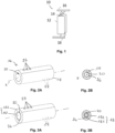
- Fig. 7 shows a sixth embodiment, sensibly similar to the embodiment of Fig. 3A , but between the core 181 and the outer sleeve 182, the body also comprises an inner sleeve 183.
- the cavity 26 may be in two parts (or in other words, there might be two cavities 261, 262).
- a first part (or first cavity 261) extends between the core 181 and the inner sleeve 183, and the second part (or second cavity 262) extends between the inner sleeve 183 and the outer sleeve 182.
- the first part and the second part are each sensibly annular.
- the inner sleeve may be connected to the outer sleeve and to the core at some connection points.
- Fig. 8A shows a cross-section view of a seventh embodiment, similar to the third embodiment of Fig. 4A and Fig. 4B , and wherein the body (and therefore the outer sleeve 182) has a square cross-section.
- the core 181 has a rectangular cross-section, but in a variant the core 181 may also have a square cross-section.
- the eighth embodiment, disclosed in Fig. 8B comprises a hollow body with a square cross-section.
- the ninth embodiment comprises a hollow body with a rectangular cross-section.
- the presence of a core 181 allows a further increases the electrically conductive surface and thus to increase the performance of the busbar assembly 16.
- core 181 also increases the amount of material and therefore the weight.
- a completely hollow body (as depicted in the first, fourth, eighth and ninth embodiments), allows to increase the air gap and improves the cooling efficiency by natural convection of the busbar assembly.
- busbar assemblies described above may be used in a battery system 10 as depicted in Fig. 1 .
- the busbar 18 is connected via the connector 20 to at least a first battery component
Abstract
Battery system (10) comprising at least one battery cell (12, 14) and a busbar assembly (16) and busbar assembly (16) for an electric vehicle having a busbar (18) for electric power distribution and a connector (20), wherein the busbar (18) comprises a body made of conducting material, the body being at least partially hollow, such that the busbar (18) comprises at least one conductive inner surface (22) and an air gap adapted to increase cooling efficiency by natural convection.
Description
- The present invention relates to a busbar assembly for electrical power distribution in an electric vehicle. The field of the invention is more particularly that of hybrid or electric vehicles in which the energy is stored in a storage battery.
- A busbar is a metal strip or bar that conducts electricity and is used for electrical power distribution. Electrical distribution equipment, including switchboards, switchgears, and motor control centers, use busbar conductors to connect circuit breakers and other protection equipment to loads.
- Car battery cells can be connected with busbars to make for instance battery modules and battery packs. A power supply for an electric vehicle such as a hybrid car or an electric car requires a large power output. The flow of electric current to and from the individual cells (i.e., a single electrochemical unit) is such that when several such cells are combined into successively larger assemblies (such as modules and packs), the current or voltage can be increased to generate the desired power output. In the present context, larger module and pack assemblies are made up of one or more cells joined in series (for increased voltage), parallel (for increased battery capacity) or both, and may include additional structure to ensure proper installation and operation of these cells. In this type of power supply device, the battery cells disposed adjacently to each other are electrically connected to each other by busbars each made of a conductive material.
- In a known manner, in a power supply device where battery cells are electrically connected to each other via busbar assemblies, the busbar made of a conductive material is stacked via a connector on electrode terminals (or electrode lead) of the battery cells, and stacked portions of the busbar are welded to the electrode terminals of the battery cells. With such a configuration, the battery cells can be connected to each other with small electric resistance. However, the increase in the number of cells may additionally increase a risk of the battery overheating due to heat generated by a cell.
- It is thus important for the busbars to have a structure which on the one hand ensures the rigidity required to withstand the electrodynamic stresses produced by the flow of current during normal conduction and on the other hand allows to optimize the heat flow.
- Busbars assembly comprising busbars having different shapes are known from the prior art.
- For instance document
EP2324545A1 discloses a bus system for use in electrical distribution equipment. The bus system comprises a busbar comprising a pair of oppositely facing bowl-shaped conductors, forming an octagonal cross section in which air gaps are formed. The air gap increases cooling efficiency by natural convection by exposing more surface area of the conductors directly to the air flow. -
EP1131868A1 discloses a busbar having a C-shaped cross-section. The C-shaped cross-section allows a modular geometry. - However, such arrangement does not allow to deal with the thermal management of the busbar without decreasing the performance of such busbars.
- The present disclosure is designed to solve the problems mentioned above. Accordingly, the present invention provides, the present disclosure is directed to a busbar assembly for an electric vehicle according to claim 1. The busbar assembly has a busbar for electric power distribution and a connector. The busbar comprises a body made of conducting material, the body being at least partially hollow, such that the busbar comprises at least one inner conductive surface and an air gap adapted to increase cooling efficiency by natural convection. The connector is arranged on and/or connected to the inner conductive surface of the busbar and the outer surface of the busbar is electrically insulated.
- Such designs allows to decrease the size of the busbar without decreasing the performance. On the contrary, the contact area being on the inner surface of the busbar body, the conductive surface is increased. Besides, the hollow configuration increases the heat transfer to the environment. The amount of material used in production is reduced, so as to achieve both an economic benefit and a lighter assembly. Finally, since the connections are inside the busbar; the busbar remains touch-safe on its outer surface and is adapted to keep an electrical insulation, even in the case of fire.
- In an embodiment, the body extend longitudinally along a longitudinal axis X between a first end and a second end and has a body length L, wherein the body comprises a cavity extending longitudinally through the body from the first end to the second end. The cavity is thus through the body and the conductive surface is increased as well as the air gap for natural convection.
- In an embodiment, the body is integral. The body is made of one part and no junction are formed.
- In an embodiment, the cavity has a substantially circular or quadrangular or triangular transverse cross-section.
- In an embodiment, the body comprises a lateral aperture connected to the cavity. The lateral aperture increases the natural air convection. Air can freely flow between the gaps and will not get trapped inside the cavity. The lateral aperture allows the natural air convection inside cavity.
- In an embodiment, the lateral aperture extend longitudinally over a portion of the body length L. In another embodiment, the lateral aperture is formed by several holes. However, in other embodiments, the lateral aperture may have other shapes.
- In an embodiment, the cavity is a first cavity and the body comprises a second cavity. This increases the connecting surfaces without increasing the length of the busbar body. Besides, two air gaps are thus arranged to increase the natural convection by exposing more surface area of the conductors directly to the air flow. The two air gaps for instance communicate with each other.
- In an embodiment, the second cavity longitudinally extends through the body from the first end to the second end. The first and second cavity may each have an annular cross-section. For instance they can be concentrically arranged around the longitudinal axis.
- In an embodiment, the body has a substantially circular or quadrangular or triangular transverse cross-section. These shapes allow to easily manufacture an integral body (a body in one part, without junction) with a cavity.
- The present invention is also directed to a battery system comprising at least one battery cell and a busbar assembly according to any of the preceding claims, wherein the connector connects an electrode lead of the at least one battery cell to the busbar body.
- The invention and its advantages will be better understood from the reading of the following description, given by way of example only and with reference to the accompanying drawings, of which:
-
Fig. 1 schematically shows a first and a second busbar assembly connecting a first and a second battery component; -
Fig. 2A and Fig. 2B show a schematic perspective view and cross-section view of a busbar assembly according to a first embodiment of the invention; -
Fig. 3A and Fig. 3B show a schematic perspective view and cross-section view of a busbar assembly according to a second embodiment of the invention; -
Fig. 4A and Fig. 4B show a schematic perspective view and cross-section view of a busbar assembly according to a third embodiment of the invention; -
Fig. 5A and Fig. 5B show a schematic perspective view and cross-section view of a busbar assembly according to a fourth embodiment of the invention; -
Fig. 6A and Fig. 6B show a schematic perspective view and cross-section view of a busbar assembly according to a fifth embodiment of the invention; -
Fig. 7 shows a schematic perspective view of a busbar assembly according to a sixth embodiment of the invention; -
Fig. 8A, Fig. 8B and Fig. 8C show cross-section views of three different busbar assembly according to a seventh, eighth and ninth embodiment of the invention. - The embodiments of the disclosure will be best understood by reference to the drawings, wherein the same reference signs designate identical or similar elements. It will be readily understood that the components of the disclosed embodiments, as generally described and illustrated in the figures herein, could be arranged and designed in a wide variety of different configurations. Thus, the following detailed description of the embodiments of the systems and methods of the disclosure is not intended to limit the scope of the disclosure, as claimed, but is merely representative of possible embodiments of the disclosure.
-
Fig. 1 illustrates a portion of anexemplary battery system 10. Thebattery system 10 comprises afirst battery component 12 and asecond battery component 14. As depicted, thebattery components Busbar assemblies 16 are used to connect the battery components in this parallel arrangement. A first and asecond busbar assembly 16 are depicted inFig. 1 . Eachbusbar assembly 16 is coupled to thebattery components Battery components -
Fig. 2A to Fig. 8C show ten different embodiments ofbusbar assemblies 16 according to the invention. Thebusbar assembly 16 according to the invention comprises abusbar 18 for electric power distribution and aconnector 20. The connector electrically connects thebusbar 18 to abattery component busbar 18 comprises a body made of conducting material. The body longitudinally extend along a longitudinal axis X and has a body length L. The body is at least partially hollow and comprises aninner surface 22 and anouter surface 24. The hollow part of the busbar body forms at least one air gap. The air gap allows to increase cooling efficiency of thebusbar 18, and thus of thebusbar assembly 16 by natural convection. The hollow part for instance is formed by acavity 26. Theinner surface 22 faces thecavity 26. Theinner surface 22 delimits thecavity 26. Theinner surface 22 is for instance not painted or coated and is therefore a conductive surface. Theouter surface 24 may be painted or coated or treated or may be provided with an additional layer, to render this surface electrically insulated. Alateral aperture 28 is provided between the inner surface and theouter surface lateral aperture 28 may have different shapes, as depicted below. Theconnector 20 is arranged at least partly on theinner surface 22 of the busbar body. This allows to provide a compact busbar assembly and a good electrical conductivity. The busbar body may be integral and continue. In other words, the busbar body may be formed by one unique part and does not comprise any cut or junction. The body is for instance a molded body or an extruded part. - The
cavity 26 may have different shapes or cross sections, as notably visible inFig. 2A to Fig. 9C. Thebusbar 18 may have different cross-section shapes, as visible inFig. 2A to Fig. 9C. - For instance, in a first embodiment, depicted in
Fig. 2A and Fig. 2B , thebusbar 18 has a cylindrical form with a circular cross section. More particularly the busbar body has an annular cross section. Thecavity 26 goes through the entire body length L (in another variant of the invention, said cavity could be a blind hole having a cavity length inferior to the body length). Thelateral aperture 28 is formed by a plurality of holes arranged on the busbar body in the vicinity of a first and/or a second free end 30, 32. For instance, three holes are provided at one end, and three other holes are provided on the other end. -
Fig. 3A and Fig. 3B show a second embodiment of abusbar assembly 16 with a busbar body having a circular cross-section. Thecavity 26 has an annular cross-section such that the body comprises acore 181 and anouter sleeve 182, thecavity 26 extending between the core and the outer sleeve. Thecore 181 is for instance connected to theouter sleeve 182 at some connection points C1, C2 along the longitudinal axis X. Thecore 181 is cylindrical and theouter sleeve 182 has an annular cross-section. The core and the outer sleeve may be integral. For example, they form an extruded part. - The third embodiment, illustrated in
Fig. 4A and Fig. 4B , has a body with acore 181 and anouter sleeve 182. Thecore 181 and theouter sleeve 182 each have a rectangular cross section. Thecavity 26 has also a rectangular cross-section. Thecavity 26 extends between theouter sleeve 181 and thesleeve 182. Thelateral aperture 28 is formed by a longitudinal slit arranged on the busbar body. Thecore 181 is for instance connected to theouter sleeve 182 at some connection points C1, C2 along the longitudinal axis. The core and the outer sleeve may be integral. For example, they form an extruded part. - In
Fig. 5A, Fig. 5B, Fig. 6A and Fig. 6B , the cross-section of the body is triangular. The fourth embodiment inFig. 5A and Fig. 5B shows a hollow body, wherein in the fifth embodiment, inFig. 6A and Fig. 6B , the body comprises acore 181 and asleeve 182. Both have a triangular cross-section and thecavity 26 extends therebetween. Thelateral aperture 28 is formed by a longitudinal slit arranged on the busbar body. Thelateral aperture 28 extends longitudinally only on a portion of the body length L. Thecore 181 is for instance connected to theouter sleeve 182 at some connection points C1, C2 along the longitudinal axis X. The core and the outer sleeve may be integral. For example, they form an extruded part (only one body). -
Fig. 7 shows a sixth embodiment, sensibly similar to the embodiment ofFig. 3A , but between the core 181 and theouter sleeve 182, the body also comprises aninner sleeve 183. Thus, thecavity 26 may be in two parts (or in other words, there might be twocavities 261, 262). A first part (or first cavity 261) extends between the core 181 and theinner sleeve 183, and the second part (or second cavity 262) extends between theinner sleeve 183 and theouter sleeve 182. The first part and the second part are each sensibly annular. The inner sleeve may be connected to the outer sleeve and to the core at some connection points. -
Fig. 8A shows a cross-section view of a seventh embodiment, similar to the third embodiment ofFig. 4A and Fig. 4B , and wherein the body (and therefore the outer sleeve 182) has a square cross-section. As depicted, thecore 181 has a rectangular cross-section, but in a variant thecore 181 may also have a square cross-section. The eighth embodiment, disclosed inFig. 8B comprises a hollow body with a square cross-section. The ninth embodiment comprises a hollow body with a rectangular cross-section. - In the second, third, fifth, sixth and seventh embodiment, the presence of a
core 181 allows a further increases the electrically conductive surface and thus to increase the performance of thebusbar assembly 16. However,such core 181 also increases the amount of material and therefore the weight. On the other side, a completely hollow body (as depicted in the first, fourth, eighth and ninth embodiments), allows to increase the air gap and improves the cooling efficiency by natural convection of the busbar assembly. - The busbar assemblies described above may be used in a
battery system 10 as depicted inFig. 1 . Thebusbar 18 is connected via theconnector 20 to at least a first battery component -
battery system 10 -
first battery component 12 -
second battery component 14 -
busbar assembly 16 -
busbar 18 - body length L
- longitudinal axis X
-
connector 20 -
inner surface 22 -
outer surface 24 -
cavity 26 -
lateral aperture 28 - a first and/or a second free end 30, 32
-
core 181 -
outer sleeve 182 -
inner sleeve 183 -
first cavity 261 - second cavity 262
- connection points C1, C2
Claims (15)
- Busbar assembly (16) for an electric vehicle having a busbar (18) for electric power distribution and a connector (20), wherein the busbar (18) comprises a body made of conducting material, the body being at least partially hollow, such that the busbar (18) comprises at least one conductive inner surface (22) and an air gap adapted to increase cooling efficiency by natural convection,
characterized in that
the connector (20) is arranged on and/or connected to the inner surface (22) of the busbar (18) and the outer surface (24) of the busbar is electrically insulated. - Busbar assembly (16) according to claim 1, wherein the body extends longitudinally along a longitudinal axis (X) between a first end and a second end and has a body length L, wherein the body comprises a cavity (26) extending longitudinally through the body from the first end to the second end.
- Busbar assembly (16) according to claim 2, wherein the cavity (26) has a substantially circular or quadrangular or triangular transverse cross-section.
- Busbar assembly (16) according to claim 2 or claim 3, wherein the body comprises a lateral aperture (28) connected to the cavity (26).
- Busbar assembly (16) according to any of claims 2 to 4, wherein the lateral aperture (28) extends longitudinally over a portion of the body length L.
- Busbar assembly (16) according to any of claims 2 to 4, wherein the lateral aperture (28) is formed by several holes.
- Busbar assembly (16) according to any of claims 2 to 6, wherein the cavity (26) is a first cavity (26), and the body comprises a second cavity (26).
- Busbar assembly (16) according to claim 7, wherein the second cavity (26) longitudinally extends through the body from the first end (30) to the second end (32).
- Busbar assembly (16) according to any of claims 1 to 8, wherein the body comprises a core (181) and a sleeve (182).
- Busbar assembly (16) according to claim 9, wherein the sleeve is an outer sleeve (182), and wherein the body further comprises an inner sleeve (183).
- Busbar assembly (16) according to any of claims 1 to 9, wherein the body is integral and continue.
- Busbar assembly (16) according to any of claims 1 to 9, wherein the body has a substantially circular transverse cross-section.
- Busbar assembly (16) according to any of claims 1 to 9, wherein the body has a substantially quadrangular transverse cross-section.
- Busbar assembly (16) according to any of claims 1 to 9, wherein the body has a substantially triangular transverse cross-section.
- Battery system (10) comprising at least one battery component (12, 14) and a busbar assembly (16) according to any of the preceding claims, wherein the connector (20) connects the battery component to the busbar (18).
Priority Applications (2)
| Application Number | Priority Date | Filing Date | Title |
|---|---|---|---|
| EP22180156.6A EP4297149A1 (en) | 2022-06-21 | 2022-06-21 | Busbar assembly |
| PCT/EP2023/066726 WO2023247591A1 (en) | 2022-06-21 | 2023-06-21 | Busbar assembly |
Applications Claiming Priority (1)
| Application Number | Priority Date | Filing Date | Title |
|---|---|---|---|
| EP22180156.6A EP4297149A1 (en) | 2022-06-21 | 2022-06-21 | Busbar assembly |
Publications (1)
| Publication Number | Publication Date |
|---|---|
| EP4297149A1 true EP4297149A1 (en) | 2023-12-27 |
Family
ID=82163508
Family Applications (1)
| Application Number | Title | Priority Date | Filing Date |
|---|---|---|---|
| EP22180156.6A Pending EP4297149A1 (en) | 2022-06-21 | 2022-06-21 | Busbar assembly |
Country Status (2)
| Country | Link |
|---|---|
| EP (1) | EP4297149A1 (en) |
| WO (1) | WO2023247591A1 (en) |
Citations (6)
| Publication number | Priority date | Publication date | Assignee | Title |
|---|---|---|---|---|
| EP1131868A1 (en) | 1998-10-30 | 2001-09-12 | ABB Ricerca SpA | Bus bar for electrical power distribution |
| EP2324545A1 (en) | 2008-08-29 | 2011-05-25 | Schneider Electric USA, Inc. | Efficient high-ampacity bowl-shaped tubular conductors |
| CN103155265A (en) * | 2010-10-08 | 2013-06-12 | 株式会社自动网络技术研究所 | Bus bar module |
| US20130260611A1 (en) * | 2012-04-03 | 2013-10-03 | Jang-Gun Ahn | Battery module |
| US20200266401A1 (en) * | 2019-02-18 | 2020-08-20 | 3M Innovative Properties Company | Battery module |
| US20220131209A1 (en) * | 2019-01-21 | 2022-04-28 | 3M Innovative Properties Company | Thermal Management of Battery Modules |
-
2022
- 2022-06-21 EP EP22180156.6A patent/EP4297149A1/en active Pending
-
2023
- 2023-06-21 WO PCT/EP2023/066726 patent/WO2023247591A1/en unknown
Patent Citations (6)
| Publication number | Priority date | Publication date | Assignee | Title |
|---|---|---|---|---|
| EP1131868A1 (en) | 1998-10-30 | 2001-09-12 | ABB Ricerca SpA | Bus bar for electrical power distribution |
| EP2324545A1 (en) | 2008-08-29 | 2011-05-25 | Schneider Electric USA, Inc. | Efficient high-ampacity bowl-shaped tubular conductors |
| CN103155265A (en) * | 2010-10-08 | 2013-06-12 | 株式会社自动网络技术研究所 | Bus bar module |
| US20130260611A1 (en) * | 2012-04-03 | 2013-10-03 | Jang-Gun Ahn | Battery module |
| US20220131209A1 (en) * | 2019-01-21 | 2022-04-28 | 3M Innovative Properties Company | Thermal Management of Battery Modules |
| US20200266401A1 (en) * | 2019-02-18 | 2020-08-20 | 3M Innovative Properties Company | Battery module |
Also Published As
| Publication number | Publication date |
|---|---|
| WO2023247591A1 (en) | 2023-12-28 |
Similar Documents
| Publication | Publication Date | Title |
|---|---|---|
| JP2013532890A (en) | Batteries consisting of cells that are easy to design and assemble | |
| CN101814642B (en) | Cooling system for pile | |
| JP5501763B2 (en) | Equally distributed bus and medium or large battery pack using it | |
| US20120308849A1 (en) | Battery assembly | |
| CN106299223B (en) | battery module | |
| US11451118B2 (en) | Conductor arrangement and transportable electrical drive device | |
| JP6180848B2 (en) | Battery pack busbar and battery pack | |
| US9660242B2 (en) | Electrode board having security device and power battery system using same | |
| JP2017004741A (en) | Wiring module | |
| EP3496179B1 (en) | Connector for a battery pack | |
| CN111919311A (en) | Energy storage module having energy storage cells and/or a cooling system connected together by uninsulated wire sections, energy storage block and method for cooling an energy storage module | |
| CN106935781B (en) | Battery pack connection method | |
| EP4297149A1 (en) | Busbar assembly | |
| KR20100017261A (en) | Electrochemical cell with weld points connections and energy storage assembly | |
| CN112234296B (en) | Battery cell and battery module | |
| US20140295243A1 (en) | Connector for producing an electrically conductive connection between at least three terminals of battery cells | |
| CN112701425A (en) | Battery cell contact device and electric storage device | |
| CN213413548U (en) | Car fills female structure of arranging of electric pile power supply | |
| US20230178856A1 (en) | Two-piece current collector sub-assembly | |
| US20230275325A1 (en) | Busbar for a battery | |
| CN217306692U (en) | Battery pack, battery device, and electric device | |
| CN220671493U (en) | Test fixture and test equipment | |
| CN219917496U (en) | Battery and electric equipment | |
| CN220042114U (en) | Battery pack bottom plate assembly, battery pack electrical system and battery pack | |
| CN220420813U (en) | Battery pack and electric equipment |
Legal Events
| Date | Code | Title | Description |
|---|---|---|---|
| PUAI | Public reference made under article 153(3) epc to a published international application that has entered the european phase |
Free format text: ORIGINAL CODE: 0009012 |
|
| STAA | Information on the status of an ep patent application or granted ep patent |
Free format text: STATUS: THE APPLICATION HAS BEEN PUBLISHED |
|
| AK | Designated contracting states |
Kind code of ref document: A1 Designated state(s): AL AT BE BG CH CY CZ DE DK EE ES FI FR GB GR HR HU IE IS IT LI LT LU LV MC MK MT NL NO PL PT RO RS SE SI SK SM TR |