US8512889B1 - Battery module - Google Patents
Battery module Download PDFInfo
- Publication number
- US8512889B1 US8512889B1 US13/556,622 US201213556622A US8512889B1 US 8512889 B1 US8512889 B1 US 8512889B1 US 201213556622 A US201213556622 A US 201213556622A US 8512889 B1 US8512889 B1 US 8512889B1
- Authority
- US
- United States
- Prior art keywords
- support plate
- battery module
- projection
- plate
- opening
- Prior art date
- Legal status (The legal status is an assumption and is not a legal conclusion. Google has not performed a legal analysis and makes no representation as to the accuracy of the status listed.)
- Active
Links
Images


Classifications
-
- H—ELECTRICITY
- H01—ELECTRIC ELEMENTS
- H01M—PROCESSES OR MEANS, e.g. BATTERIES, FOR THE DIRECT CONVERSION OF CHEMICAL ENERGY INTO ELECTRICAL ENERGY
- H01M10/00—Secondary cells; Manufacture thereof
- H01M10/04—Construction or manufacture in general
- H01M10/0413—Large-sized flat cells or batteries for motive or stationary systems with plate-like electrodes
- H01M10/0418—Large-sized flat cells or batteries for motive or stationary systems with plate-like electrodes with bipolar electrodes
-
- H—ELECTRICITY
- H01—ELECTRIC ELEMENTS
- H01M—PROCESSES OR MEANS, e.g. BATTERIES, FOR THE DIRECT CONVERSION OF CHEMICAL ENERGY INTO ELECTRICAL ENERGY
- H01M10/00—Secondary cells; Manufacture thereof
- H01M10/04—Construction or manufacture in general
- H01M10/0436—Small-sized flat cells or batteries for portable equipment
-
- H—ELECTRICITY
- H01—ELECTRIC ELEMENTS
- H01M—PROCESSES OR MEANS, e.g. BATTERIES, FOR THE DIRECT CONVERSION OF CHEMICAL ENERGY INTO ELECTRICAL ENERGY
- H01M2220/00—Batteries for particular applications
- H01M2220/20—Batteries in motive systems, e.g. vehicle, ship, plane
-
- H—ELECTRICITY
- H01—ELECTRIC ELEMENTS
- H01M—PROCESSES OR MEANS, e.g. BATTERIES, FOR THE DIRECT CONVERSION OF CHEMICAL ENERGY INTO ELECTRICAL ENERGY
- H01M50/00—Constructional details or processes of manufacture of the non-active parts of electrochemical cells other than fuel cells, e.g. hybrid cells
- H01M50/20—Mountings; Secondary casings or frames; Racks, modules or packs; Suspension devices; Shock absorbers; Transport or carrying devices; Holders
- H01M50/204—Racks, modules or packs for multiple batteries or multiple cells
- H01M50/207—Racks, modules or packs for multiple batteries or multiple cells characterised by their shape
- H01M50/209—Racks, modules or packs for multiple batteries or multiple cells characterised by their shape adapted for prismatic or rectangular cells
-
- Y—GENERAL TAGGING OF NEW TECHNOLOGICAL DEVELOPMENTS; GENERAL TAGGING OF CROSS-SECTIONAL TECHNOLOGIES SPANNING OVER SEVERAL SECTIONS OF THE IPC; TECHNICAL SUBJECTS COVERED BY FORMER USPC CROSS-REFERENCE ART COLLECTIONS [XRACs] AND DIGESTS
- Y02—TECHNOLOGIES OR APPLICATIONS FOR MITIGATION OR ADAPTATION AGAINST CLIMATE CHANGE
- Y02E—REDUCTION OF GREENHOUSE GAS [GHG] EMISSIONS, RELATED TO ENERGY GENERATION, TRANSMISSION OR DISTRIBUTION
- Y02E60/00—Enabling technologies; Technologies with a potential or indirect contribution to GHG emissions mitigation
- Y02E60/10—Energy storage using batteries
-
- Y—GENERAL TAGGING OF NEW TECHNOLOGICAL DEVELOPMENTS; GENERAL TAGGING OF CROSS-SECTIONAL TECHNOLOGIES SPANNING OVER SEVERAL SECTIONS OF THE IPC; TECHNICAL SUBJECTS COVERED BY FORMER USPC CROSS-REFERENCE ART COLLECTIONS [XRACs] AND DIGESTS
- Y02—TECHNOLOGIES OR APPLICATIONS FOR MITIGATION OR ADAPTATION AGAINST CLIMATE CHANGE
- Y02P—CLIMATE CHANGE MITIGATION TECHNOLOGIES IN THE PRODUCTION OR PROCESSING OF GOODS
- Y02P70/00—Climate change mitigation technologies in the production process for final industrial or consumer products
- Y02P70/50—Manufacturing or production processes characterised by the final manufactured product
Definitions
- the battery cells may include, e.g., a non-aqueous electrolyte with high energy density.
- a large-capacity battery module may be configured by connecting a plurality of battery cells in series.
- the battery modules may be used in driving motors of devices requiring high power, e.g., electric vehicles and the like.
- Embodiments may be realized by providing a battery module including a plurality of battery cells, a support plate adjacent to sides of the plurality of battery cells, the support plate including an opening, and a first end plate that is adjacent to the support plate.
- the first end plate may include a projection that engages with the opening to couple together the first end plate and the support plate.
- the opening may expose at least one of the plurality of battery cells.
- the first end plate may be affixed to the support plate with only an opening projection connection between the opening and the projection.
- the opening-projection connection may be free of any separate fastening member.
- the projection may be a bent portion of the first end plate.
- a lateral end of the projection may be in a non-overlapping relationship with the plurality of battery cells.
- the projection may include an extending portion that extends through the opening, and a bending portion that is bent from the extending portion. The lateral end of the projection may be on the bending portion.
- a length of the extending portion may be substantially equal to a thickness of the support plate.
- the bending portion may be adjacent to an outer surface of the support plate.
- An inner surface of the support plate may be adjacent to the sides of the plurality of battery cells.
- the bending portion may include a protrusion that corresponds to an indentation on the outer surface of the support plate.
- the battery module may include a second end plate.
- the first end plate may be adjacent to a first region of the support plate and the second end plate may be adjacent to a second region of the support plate.
- the second region may oppose the first region.
- the second end plate may be fastened to the second region of the support plate.
- the first end plate may be affixed adjacent to the first region of the support plate without being fastened with any separate fastening member.
- the first end plate may have a first configuration that includes the projection and the second end plate may have a second configuration.
- the first configuration may be different from the second configuration.
- the opening may include a plurality of openings in the support plate.
- the projection may include a plurality of projections. The plurality of projections may be spaced apart from each other and may be coupled to the plurality of openings.
- the plurality of openings in the support plate may be spaced apart from each other, each opening may receive one of the plurality of projections extending thereto, and the one of the plurality of projections may be in contact with a sidewall of the opening.
- the first end plate may include a base portion that is substantially parallel to wide faces of the plurality of battery cells.
- the projection may be integrally formed as one continuous piece bent from the base portion.
- the projection may be seated on a first region of the support plate. The first region of the support plate may be adjacent to the first end plate.
- the support plate may be one of a plurality of support plates arranged adjacent to different sides of the plurality of battery cells.
- the opening may be one of a plurality of openings in the support plates.
- the projection may be one of a plurality of projections extending from a base portion of the first end plate. Each projection may extend through one of the openings.
- Inner surfaces of the plurality of support plates may face the plurality of battery cells.
- the plurality of projections may be seated on outer surfaces of the support plates. The projections may be in contact with sidewalls of the plurality of openings.
- the support plate may be one of a plurality of support plates arranged adjacent to different sides of the plurality of battery cells.
- the plurality of support plates may be one continuous piece.
- the support plate may include a frame end portion. A first surface of the frame end portion may be adjacent to the first end plate and a second surface of the frame end portion may oppose the first surface.
- the projection may be in contact with the second surface.
- the support plate may include a frame end portion that defines an outermost side of the support plate and that defines a sidewall of the opening.
- the frame end portion may be in a non-overlapping relationship with the plurality of battery cells.
- the projection may be in contact with the frame end portion and the sidewall of the opening.
- Embodiments may also be realized by providing a battery module that includes a plurality of battery cells arranged in one direction, first and second end plates respectively disposed at outsides of the battery cells, and one or more support plates coupled to the first and second end plates. One and the other ends of the support plate are respectively coupled to the first and second end plates, and at least one of the support plates is coupled to at least one of the first and second end plates by a groove-projection connection.
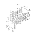
- FIG. 1 illustrates a perspective view of a battery module according to an exemplary embodiment.
- FIG. 2 illustrates an exploded perspective view of the battery module shown in FIG. 1 .
- FIG. 3 illustrates a perspective view showing a first end plate and a support plate of FIG. 1 .
- FIG. 4 illustrates an enlarged view showing portion A of FIG. 1 .
- FIG. 5 illustrates a perspective view showing a second end plate and the support plate of FIG. 1 .
- FIG. 6 illustrates a perspective view showing a first end plate and a support plate according to an exemplary embodiment.
- FIG. 7A illustrates an enlarged view showing first and third coupling members of FIG. 6 .
- FIG. 7B illustrates a sectional view taken along line X-X′ of FIG. 7A .
- FIG. 8 illustrates a perspective view of a battery module according to an exemplary embodiment.
- FIG. 9 illustrates a perspective view showing first and second end plates and a support plate of FIG. 8 .
- a layer or element when a layer or element is referred to as being “on” another layer or substrate, it can be directly on the other layer or substrate, or intervening layers may also be present. Further, it will be understood that when a layer is referred to as being “under” another layer, it can be directly under, and one or more intervening layers may also be present. In addition, it will also be understood that when a layer is referred to as being “between” two layers, it can be the only layer between the two layers, or one or more intervening layers may also be present. Also, when an element is referred to as being “coupled to” another element, it can be directly coupled to the element or be indirectly coupled to the element with one or more intervening elements interposed therebetween.
- FIG. 1 illustrates a perspective view of a battery module according to an exemplary embodiment.
- FIG. 2 illustrates an exploded perspective view of the battery module shown in FIG. 1 .
- the battery module 100 includes a plurality of battery cells 10 arranged in one direction, e.g., the battery cells 10 may be arranged in parallel to each other.
- First and second end plates 110 and 120 may be disposed at outsides, e.g., opposing ends, of the plurality of battery cells 10 .
- One or more support plates 130 may be coupled to the first and second end plates 110 and 120 .
- One and the other ends of the support plate 130 may be respectively coupled to the first and second end plates 110 and 120 .
- opposing ends of each support plate 130 may be connected to the first and second end plates 110 and 120 , respectively.
- At least one support plate 130 may be coupled to at least one of the first and second end plates 110 and 120 by a groove-projection connection.
- at least one of the first and second end plates 110 and 120 may be affixed to at least one of the support plates 130 with an opening-projection connection.
- the first end plate 110 may be affixed to two separate support plates 130 by way of openings, e.g., a third coupling portion 132 , in the support plates 130 and projections, e.g., a first coupling portion 112 , extending from the first end plate 110 .
- the battery cell 10 may include a battery case having one opened surface, and an electrode assembly and an electrolyte, accommodated in the battery case.
- the electrode assembly and the electrolyte may generate energy through an electrochemical reaction.
- the battery case may be sealed, e.g., the one opening surface of the battery case, by a first surface 14 of the battery cell 10 .
- the first surface 14 of the battery cell 10 may include a cap assembly.
- the first surface may be provided with positive and negative electrode terminals 11 and 12 having different polarities, and a vent portion 13 .
- the vent portion 13 is, e.g., a safety means of the battery cell 10 .
- the vent portion 130 act as a path through which gas generated in the inside of the battery cell 10 may be exhausted to an outside of the battery cell 10 .
- Adjacent battery cells 10 may be electrically connected through a bus-bar 15 .
- the bus-bar 15 may be fixed to the positive and negative electrode terminals 11 and 12 by, e.g., a
- the battery module 100 may include the first and second end plates 110 and 120 and the support plates 130 .
- the first end plate 110 , the second end plate 120 , and the support plates 130 may together fix the plurality of battery cells 10 in the one direction, e.g., all of the plurality of battery cells 10 may be provided between the first and second end plates 110 and 120 and the support plates 130 may be adjacent to lateral side surfaces of all of the plurality of battery cells 10 .
- the first and second end plates 110 and 120 may be provided to face wide surfaces of the outermost battery cells 10 , respectively, of the plurality of battery cells 10 .
- the first and second end plates 110 and 120 may press the battery cells 10 in the inside direction of the battery cells 10 , and the support plates 130 may fix sides of the battery cells 10 .
- First and second ends of the support plate 130 are respectively coupled to the first and second end plates 110 and 120 .
- At least one of the support plates 130 may be coupled to at least one of the first and second end plates 110 and 120 by the groove-projection connection, e.g., an opening in the support plate 130 may have a projection member from one of the first and second end plates 110 and 120 extending therethrough to form an opening-projection connection therebetween.
- the first end plate 110 may include first coupling portions 112 and the second end plate 120 may include second coupling portions 122 .
- the first coupling portions 112 may have a different shape and a different structure from the second coupling portions 122 .
- Third and fourth coupling portions 132 and 133 may be provided at opposing ends of the support plate 130 , respectively.
- the third and fourth coupling portions 132 and 133 may be formed to accommodate the shapes and structures of the first coupling portions 112 and the second coupling portions 122 , respectively. Accordingly, the third and fourth coupling portions 132 and 133 may be coupled to the first and second coupling portions 112 and 122 , respectively.
- the third coupling portion 132 may be at least one opening, e.g., a through hole, in the support plate 130 .
- the opening in the support plate 130 may expose at least one of the plurality of battery cells 10 .
- the third coupling portion 132 may expose a lateral side of a battery cell 10 that is adjacent to the first end plate 110 .
- the third coupling portion 132 may also expose a portion of a lateral side of the first end plate 110 .
- the support plate 130 may include other openings that expose lateral sides of the plurality of battery cells 10 .
- the other openings are different from the third coupling portion 132 because the other openings, e.g., exclude opening-projection connections with at least one of the first and second end plates 110 and 120 .
- the fourth coupling portion 133 may be a projection extending from the support plates 130 .
- the fourth coupling portion 133 may be used for affixing, e.g., by using a fastening member, the second plate 120 to the support plate 130 .
- the fourth coupling portion 133 may include a through hole 133 a for accommodating a separate fastening member 20 such as a fastening bolt to extend therethrough.
- the separate fastening member 20 may also extend through a through hole 122 a , which is in the corresponding second coupling portion 122 .
- the fourth coupling portion 133 may be in a non-overlapping relationship with the plurality of battery cells 10 , e.g., the through hole 133 a may not expose any of the plurality of battery cells 10 . Accordingly, the second coupling portion 122 and the fourth coupling portion 133 may be affixed using a different arrangement than that used for fixing the first coupling portion 112 and the third coupling portion 132 .
- the first and third coupling portions 112 and 132 may be coupled to each other by the groove-projection connection.
- the first coupling portion 112 may be a projection extending from the first end plate 110 and the third coupling portion 132 may be an opening to form the opening-projection connection to couple together the first end plate 110 and the support plate 130 .
- the first and second end plates 110 and 120 may include first and second base portions 111 and 121 , respectively, which face the battery cells 10 .
- the first coupling portion 112 may be provided on the first base portion 111 , e.g., as a projection having a first width that extends from the first base portion 111 having a second width that is greater than the first width.
- the second coupling portions 122 may be provided on the second base portion 121 , e.g., as an extending member having a third width that extends from the second base portion 121 having a fourth width that is greater than the third width.
- the first and second coupling portions 112 and 122 may be provided on a plurality of sides, e.g., both left and right sides, of the first and second base portions 111 and 121 , respectively.
- FIG. 3 illustrates a perspective view showing the first end plate 110 and the support plate 130 of FIG. 1 .
- FIG. 4 illustrates an enlarged view showing portion A of FIG. 1 .
- the support plate 130 may include a substantially rectangular planar member 131 overlapping, e.g., supporting, the sides of the battery cells 10 .
- the third and fourth coupling portions 132 and 133 may be provided at opposing ends of the planar member 131 .
- the third coupling portion 132 may include one or more openings provided at one end of the planar member 131 .
- the fourth coupling portions 133 may include one or more extending members extending from the opposing ends of the planar member 131 .
- the planar member 131 may include a frame end portion that defines an outermost side of the support plate 130 and that defines one sidewall of the third coupling portion 132 .
- a first surface of the frame end portion of the planar member 131 may be adjacent to the first end plate 110 .
- a second surface of the frame end portion of the planar member 131 which second surface opposes the first surface, may be in contact with the first coupling portion 131 .
- the first coupling portion 131 may also be in contact with the sidewall of the third coupling portion 132 that is defined by the frame end portion.
- the frame end portion of the planar member 131 may be in a non-overlapping relationship with the plurality of battery cells 10 .
- a battery module having improved productivity may be realized by facilitating the coupling between the first and second end plates and the support plates. For example, a separate coupling member may be omitted, and thus it may be possible to reduce the possibility of and/or prevent a failure from occurring when the coupling member is omitted in a process.
- the first coupling portion 112 may include a plurality of first coupling portions 112 .
- Each of the first coupling portions 112 of the first end plate 110 may include an extending portion 112 a and a bending portion 112 b .
- the extending portions 112 a may extend in a first direction that is substantially parallel to the first base portion 111 .
- a plurality of extending portions 112 a may be formed on opposing sides of the first base portion 111 .
- the bending portions 112 b may be bent in a second direction that intersects the first direction, e.g., in the opposite direction of the battery cells 10 (see FIG. 1 ) from the extending portion 112 a .
- each of the bending portions 112 b may be substantially perpendicular to corresponding ones of the extending portions 112 a.
- the first base portion 111 , the extending portion 112 a , and the bending portion 112 b may be integrally formed as one continuous piece or may be assembled together.
- the bending portion 112 b may extend directly from the extending portion 112 a .
- the length “s” of the extending portion 112 a may be provided to correspond to the thickness “t” of the support plate 130 . Accordingly, the extending portion 112 a may extend through the third coupling portion 132 , e.g., the extending portion 112 a may be in direct contact with sidewalls of the third coupling portion 132 .
- the bending portion 112 b may be adjacent to an outer surface of the support plate 130 , e.g., may be directly on the outer surface of the support plate 130 .
- the outer surface of the support plate 130 may be opposite an inner surface of the support plate 130 that is adjacent to the sides of the plurality of battery cells 10 .
- the first end plate 110 and the support plate 130 may be coupled to each other by the first and third coupling portions 112 and 132 .
- a separate coupling member such as a fastening member that is one of a bolt or stud may not be required.
- an opening-projection connection between the first and third coupling portions 112 and 132 may be free of any separate fastening member.
- the support plates 130 may be respectively provided at different sides, e.g., opposing sides, of the first end plate 110 , and the first coupling portion 112 may pass through the third coupling portion 132 .
- the first end plate 110 and the support plate 130 may be easily arranged with each other, e.g., affixed to each other using an interlocking relationship without any separate fastening member. Subsequently, the first and third coupling portions 112 and 132 may be overlapped with each other by moving the first end plate 110 in the outside direction of the battery cells 10 . Thus, the first end plate 110 and the support plate 130 may be coupled to each other at an exact position without using a separate coupling member.
- the length “s” of the extending portion 112 a in the first coupling portion 112 may be provided to correspond to the thickness “t” of the support plate 130 . That is, the extending portion 112 a and the bending portion 112 b in the first coupling portion 112 may be provided to surround the third coupling portion 132 , so as to fix the third coupling portion 132 .
- the coupling performance between the first end plate 110 and the support plate 130 may be improved.
- a predetermined space may be first provided by coupling the first end plate 110 and the support plate 130 , and the plurality of battery cells may be arranged in the predetermined space.
- FIG. 5 illustrates a perspective view showing the second end plate 120 and the support plate 130 of FIG. 1 .
- the support plate 130 may include the third and fourth coupling portions 132 and 133 respectively provided at opposing ends of the planar member 131 .
- the fourth coupling portion 132 may include one or more projection portions extended from the other end of the planar member 131 , e.g., a width of the projection portions may be less than a width of the planar member 131 .
- the second end plate 120 may include the second coupling portions 122 bent to be extended in the opposite direction of the battery cells 10 (see FIG. 1 ) from the second base portion 121 .
- the second coupling portions 122 may be in a non-overlapping relationship with the battery cells 10 .
- the second and fourth coupling portions 122 and 133 may include the through-holes 122 a and 133 a , respectively, provided to correspond to each other.
- Each of the second coupling portions 122 may correspond to one of the fourth coupling portions 133 .
- the sizes of the first and second base portions 111 and 121 , respectively, provided to the first and second end plates 110 and 120 may be provided to correspond to each other.
- the size, e.g., a length and a width, of the first and second base portions 111 and 121 may correspond to a side, e.g., a length and a width, of the wide surface of the battery cells 10 .
- the first end plate 110 and the support plate 130 may first be fixed to each other, e.g., using the opening-projection connection. Then, the plurality of battery cells may be pressed in the inside direction thereof in the state in which the plurality of battery cells 10 are arranged. Thereafter, the second end plate 120 and the support plate 130 may be coupled to each other, e.g., using a fastening member such as the separate fastening member 20 .
- the second coupling portion 122 of the second end plate 120 may be overlapped with the fourth coupling portion 133 of the support plate 130 , and the corresponding through-holes 122 a and 133 a respectively provided to the second and fourth coupling portions 122 and 133 , respective, may be aligned with each other.
- the through-holes 122 a and 133 a may be coupled by passing the separate fastening member 20 therethrough. Accordingly, the plurality of battery cells 10 may be firmly fixed to form a battery module.
- the fastening member 20 may be a bolt or a stud.
- FIG. 6 illustrates a perspective view showing a first end plate 210 and a support plate 230 according to another exemplary embodiment.
- FIG. 7A illustrates an enlarged view showing first and third coupling portions 210 and 232 .
- FIG. 7B illustrates a sectional view taken along line X-X′ of FIG. 7A .
- one end of a support plate 230 may be coupled to a first end plate 210 by a groove-projection connection, e.g., an opening-projection connection.
- the first end plate 210 may include a first base portion 211 and at least one first coupling portion 212 .
- the at least one first coupling portion 212 may be provided extending from sides, e.g., opposing sides, of the first base portion 211 .
- At least one third coupling portion 232 in the support plate 230 may be provided to correspond to the first coupling portions 212 , e.g., a plurality of the third coupling portions 231 may be provided at one end of the support plate 230 .
- Each of the first coupling portions 212 may include an extending portion 212 a and a bending portion 212 b .
- the extending portion 212 a and the bending portion 212 b may be overlapped with each other so as to correspond to the shape of the third coupling portion 232 .
- the bending portion 212 b may be seated on an outer surface of the support plate 230 .
- a surface of the bending portion 212 b may include one or more projections 215 formed thereon.
- the projection 215 may be formed at the part of the bending portion 212 b contacting the outer surface of support plate 230 .
- the outer surface of the support plate 230 may include one or more grooves 235 respectively corresponding to the one or more projections 215 on the bending portion 212 b .
- the projections 215 and the grooves 235 may be respectively provided at the parts at which the first and second coupling portions 212 and 232 are overlapped with each other, so that the first end plate 210 and the support plate 230 may be more firmly coupled to each other.
- FIG. 8 illustrates a perspective view of a battery module according to another exemplary embodiment.
- FIG. 9 illustrates a perspective view showing first and second end plates 310 and 320 and a support plate 330 of FIG. 8 .
- Contents of these embodiments, except the following content, are similar to those of the embodiment described in FIGS. 1 to 5 , and therefore, repeated detailed descriptions will be omitted.
- the battery module 300 may include a plurality of battery cells 10 , first and second end plates 310 and 320 fixing the battery cells 10 , and a support plate 330 .
- the first end plate 310 may be coupled to the support plate 330 without using any separate fastening member, e.g., the separate fastening member 20 is not used in the coupling of the first end plate 310 to the support plate 330 .
- ends of first and second plates 330 a and 330 b of the support plate 330 may include third coupling portions 332 respectively corresponding to first coupling portions 312 of the first end plate 310 .
- the other ends of the first and second plates 330 a and 330 b may include fourth coupling portions 333 respectively corresponding to second coupling portions 322 .
- the support plate 330 may include a pair of the first plates 330 a supporting side surfaces of the battery cells 10 , and the second plate 330 b supporting bottom surfaces of the battery cells 10 .
- the first plates 330 a may be integrally provided by being coupled to the second plate 330 b , i.e., the first and second plates 330 a and 330 b may be integrally formed as one continuous piece in which the plurality of battery cells 10 may be seated therein.
- the first and second plates 330 a and 330 b may be assembled together, prior to having the plurality of battery cells 10 seated therein.
- the pair of first plates 330 a may be provided to support opposing sides of the battery cells 10 , and the pair of first plates 330 a may be coupled to the second plate 330 b . Accordingly, the section formed by the first and second plates 330 a and 330 b may be provided to have a ‘U’ shape.
- the first end plate 310 may be fixed to one end of the support plate 330 , e.g., by being coupled to each other by coupling the first coupling portion 312 of the first end plate 310 and the third coupling portion 332 in the support plate 330 . Subsequently, the plurality of battery cells 10 may be arranged between the first end plate 310 and the support plate 330 .
- the fourth coupling portion 333 may be coupled to the second coupling portion 322 , so that the second end plate 320 can be coupled to the support plate 330 .
- the first and second end plates 310 and 320 may have the first and second coupling portions 312 and 322 provided at opposing sides and bottoms of the first and second base portions 311 and 321 , respectively.
- the first and second coupling portions 312 and 322 may be coupled to the second plate 330 b of the support plate 330 , so that the battery module 300 may be more firmly fixed.
- the first end plate 310 may include a plurality of first coupling portions 312 arranged on at least three different sides of the first end plate 310 .
- Each of the first coupling portions 312 may have a corresponding third coupling portion 332 in the support plate 330 .
- the members may include end plates and support plates that are affixed to each other.
- Embodiments include configurations between the end plates and support plates in which at least one separate fastening member may be omitted.
- Improved productivity e.g., in forming a battery module, may be realized by facilitating coupling between the first and second end plates and the support plates.
- a separate coupling member may be omitted, and thus it may be possible to reduce the possibility of and/or prevent a failure from occurring by omitting the process that entails the use of a separate fastening member.
- Embodiments also provide a battery module in which battery cells are firmly fixed so that the battery cells may not be moved by an external force.
Landscapes
- Chemical & Material Sciences (AREA)
- Chemical Kinetics & Catalysis (AREA)
- Electrochemistry (AREA)
- General Chemical & Material Sciences (AREA)
- Engineering & Computer Science (AREA)
- Manufacturing & Machinery (AREA)
- Battery Mounting, Suspending (AREA)
Abstract
Description
Claims (20)
Priority Applications (5)
| Application Number | Priority Date | Filing Date | Title |
|---|---|---|---|
| US13/556,622 US8512889B1 (en) | 2012-02-27 | 2012-07-24 | Battery module |
| CN201210325587.4A CN103296230B (en) | 2012-02-27 | 2012-09-05 | Battery module |
| EP13154775.4A EP2631965B1 (en) | 2012-02-27 | 2013-02-11 | Battery module |
| KR1020130019313A KR101730960B1 (en) | 2012-02-27 | 2013-02-22 | Battery module having interlocking |
| JP2013037127A JP6110687B2 (en) | 2012-02-27 | 2013-02-27 | Battery module |
Applications Claiming Priority (2)
| Application Number | Priority Date | Filing Date | Title |
|---|---|---|---|
| US201261603582P | 2012-02-27 | 2012-02-27 | |
| US13/556,622 US8512889B1 (en) | 2012-02-27 | 2012-07-24 | Battery module |
Publications (2)
| Publication Number | Publication Date |
|---|---|
| US8512889B1 true US8512889B1 (en) | 2013-08-20 |
| US20130224547A1 US20130224547A1 (en) | 2013-08-29 |
Family
ID=47722077
Family Applications (1)
| Application Number | Title | Priority Date | Filing Date |
|---|---|---|---|
| US13/556,622 Active US8512889B1 (en) | 2012-02-27 | 2012-07-24 | Battery module |
Country Status (5)
| Country | Link |
|---|---|
| US (1) | US8512889B1 (en) |
| EP (1) | EP2631965B1 (en) |
| JP (1) | JP6110687B2 (en) |
| KR (1) | KR101730960B1 (en) |
| CN (1) | CN103296230B (en) |
Cited By (7)
| Publication number | Priority date | Publication date | Assignee | Title |
|---|---|---|---|---|
| USD795180S1 (en) * | 2013-02-04 | 2017-08-22 | Sumitomo Electric Industries, Ltd. | Redox flow battery cell stack |
| EP3288098A4 (en) * | 2015-08-19 | 2018-02-28 | LG Chem, Ltd. | Battery module, battery pack including battery module, and automobile including battery pack |
| US10388925B2 (en) | 2016-04-21 | 2019-08-20 | Contemporary Amperex Technology Co., Limited | Battery module |
| US10446816B2 (en) | 2016-11-17 | 2019-10-15 | Lg Chem, Ltd. | Battery module, and battery pack comprising same |
| US10586960B2 (en) | 2015-12-09 | 2020-03-10 | Lg Chem, Ltd. | Battery module comprising end plates having improved strucutre, and end plate member therefor |
| CN110998908A (en) * | 2017-09-26 | 2020-04-10 | 松下知识产权经营株式会社 | Restraint member and battery module |
| US20220352588A1 (en) * | 2021-04-30 | 2022-11-03 | Caterpillar Inc. | Housing for securing battery cells in a battery module |
Families Citing this family (12)
| Publication number | Priority date | Publication date | Assignee | Title |
|---|---|---|---|---|
| KR20150031095A (en) * | 2013-09-13 | 2015-03-23 | 삼성에스디아이 주식회사 | Battery pack |
| KR102222888B1 (en) * | 2014-04-09 | 2021-03-04 | 삼성에스디아이 주식회사 | Battery module |
| JP6305260B2 (en) | 2014-07-30 | 2018-04-04 | 株式会社Gsユアサ | Power storage device |
| JP6372232B2 (en) * | 2014-08-05 | 2018-08-15 | 株式会社豊田自動織機 | Battery module |
| JP6441710B2 (en) * | 2015-02-27 | 2018-12-19 | 本田技研工業株式会社 | Power storage device |
| DE102015205485A1 (en) * | 2015-03-26 | 2016-09-29 | Robert Bosch Gmbh | Battery housing, battery with such a battery case, plate member for producing such a battery case and method for producing such a battery case |
| JP6831632B2 (en) * | 2016-02-19 | 2021-02-17 | 株式会社Gsユアサ | Power storage device and manufacturing method of the power storage device |
| JP7061547B2 (en) * | 2018-10-02 | 2022-04-28 | 本田技研工業株式会社 | Battery module and method of manufacturing battery module |
| CN110061165A (en) * | 2019-04-12 | 2019-07-26 | 国机智骏科技有限公司 | Battery modules and vehicle with it |
| KR102391985B1 (en) | 2019-06-14 | 2022-04-27 | 주식회사 엘지에너지솔루션 | Battery module and manufacturing method thereof |
| EP4099351A4 (en) * | 2020-01-31 | 2023-07-05 | Panasonic Intellectual Property Management Co., Ltd. | Electrical storage module |
| JP2022184503A (en) * | 2021-06-01 | 2022-12-13 | トヨタ自動車株式会社 | Battery case and manufacturing method of battery case |
Citations (9)
| Publication number | Priority date | Publication date | Assignee | Title |
|---|---|---|---|---|
| US6455190B1 (en) * | 1999-09-21 | 2002-09-24 | Matsushita Electric Industrial Co. Ltd. | Battery module, and connecting structure of cells in the battery module |
| US20040043287A1 (en) * | 2002-03-05 | 2004-03-04 | Masashi Bando | Battery-type power supply unit |
| US6761992B1 (en) * | 1999-08-31 | 2004-07-13 | Matsushita Electric Industrial Co., Ltd. | Restraining bands for battery pack |
| US20050100783A1 (en) * | 2003-10-14 | 2005-05-12 | Ro Jong Y. | Cartridge-type lithium ion polymer battery pack |
| KR20070081584A (en) | 2006-02-13 | 2007-08-17 | 주식회사 엘지화학 | Medium and large size battery module of vertical stacking structure |
| US20080118819A1 (en) * | 2006-11-17 | 2008-05-22 | Paul Gamboa | Modular battery system |
| US20100190055A1 (en) * | 2009-01-29 | 2010-07-29 | Gm Global Technology Operations, Inc. | Battery cell connection method and apparatus |
| KR20100095457A (en) | 2007-12-05 | 2010-08-30 | 에네르델, 인코포레이티드 | Battery assembly with temperature control device |
| US20110039130A1 (en) * | 2007-12-14 | 2011-02-17 | Lg Chem, Ltd. | Pcm of improved assembling type structure and battery pack employed with the same |
Family Cites Families (11)
| Publication number | Priority date | Publication date | Assignee | Title |
|---|---|---|---|---|
| FR2344133A1 (en) * | 1976-03-09 | 1977-10-07 | Accumulateurs Fixes | ACCUMULATOR BATTERY CHASSIS |
| JP4609623B2 (en) * | 2003-05-26 | 2011-01-12 | トヨタ自動車株式会社 | Battery binder |
| KR100850866B1 (en) * | 2005-12-27 | 2008-08-07 | 주식회사 엘지화학 | Frame Member for Preparation of Battery Pack |
| JP2007280890A (en) * | 2006-04-11 | 2007-10-25 | Toyota Motor Corp | Fastening structure of fuel cell stack, and fuel cell having it |
| JP2008277085A (en) | 2007-04-27 | 2008-11-13 | Sanyo Electric Co Ltd | Battery pack |
| US20090159354A1 (en) * | 2007-12-25 | 2009-06-25 | Wenfeng Jiang | Battery system having interconnected battery packs each having multiple electrochemical storage cells |
| KR101084222B1 (en) * | 2009-11-03 | 2011-11-17 | 에스비리모티브 주식회사 | Battery module providing improved base plate |
| KR101182426B1 (en) * | 2009-12-04 | 2012-09-12 | 에스비리모티브 주식회사 | Battery module and battery pack having the same |
| KR101084223B1 (en) * | 2009-12-18 | 2011-11-17 | 에스비리모티브 주식회사 | Battery module providing improved fixing structure for restrainer and the fixing method thereof |
| US8999557B2 (en) * | 2010-04-21 | 2015-04-07 | Samsung Sdi Co., Ltd. | Battery pack with elastic frame |
| KR101126889B1 (en) * | 2010-05-31 | 2012-03-20 | 에스비리모티브 주식회사 | Battery pack |
-
2012
- 2012-07-24 US US13/556,622 patent/US8512889B1/en active Active
- 2012-09-05 CN CN201210325587.4A patent/CN103296230B/en active Active
-
2013
- 2013-02-11 EP EP13154775.4A patent/EP2631965B1/en active Active
- 2013-02-22 KR KR1020130019313A patent/KR101730960B1/en active IP Right Grant
- 2013-02-27 JP JP2013037127A patent/JP6110687B2/en active Active
Patent Citations (11)
| Publication number | Priority date | Publication date | Assignee | Title |
|---|---|---|---|---|
| US6761992B1 (en) * | 1999-08-31 | 2004-07-13 | Matsushita Electric Industrial Co., Ltd. | Restraining bands for battery pack |
| US6455190B1 (en) * | 1999-09-21 | 2002-09-24 | Matsushita Electric Industrial Co. Ltd. | Battery module, and connecting structure of cells in the battery module |
| US20040043287A1 (en) * | 2002-03-05 | 2004-03-04 | Masashi Bando | Battery-type power supply unit |
| US20050100783A1 (en) * | 2003-10-14 | 2005-05-12 | Ro Jong Y. | Cartridge-type lithium ion polymer battery pack |
| KR20070081584A (en) | 2006-02-13 | 2007-08-17 | 주식회사 엘지화학 | Medium and large size battery module of vertical stacking structure |
| US20100255363A1 (en) | 2006-02-13 | 2010-10-07 | Lg Chem, Ltd. | Medium and Large Size Battery Module of Vertical Stacking Structure |
| US20080118819A1 (en) * | 2006-11-17 | 2008-05-22 | Paul Gamboa | Modular battery system |
| KR20100095457A (en) | 2007-12-05 | 2010-08-30 | 에네르델, 인코포레이티드 | Battery assembly with temperature control device |
| US20100273042A1 (en) | 2007-12-05 | 2010-10-28 | Buck Derrick S | Battery assembly with temperature control device |
| US20110039130A1 (en) * | 2007-12-14 | 2011-02-17 | Lg Chem, Ltd. | Pcm of improved assembling type structure and battery pack employed with the same |
| US20100190055A1 (en) * | 2009-01-29 | 2010-07-29 | Gm Global Technology Operations, Inc. | Battery cell connection method and apparatus |
Cited By (8)
| Publication number | Priority date | Publication date | Assignee | Title |
|---|---|---|---|---|
| USD795180S1 (en) * | 2013-02-04 | 2017-08-22 | Sumitomo Electric Industries, Ltd. | Redox flow battery cell stack |
| EP3288098A4 (en) * | 2015-08-19 | 2018-02-28 | LG Chem, Ltd. | Battery module, battery pack including battery module, and automobile including battery pack |
| US10497911B2 (en) | 2015-08-19 | 2019-12-03 | Lg Chem, Ltd. | Battery module, battery pack including battery module, and automobile including battery pack |
| US10586960B2 (en) | 2015-12-09 | 2020-03-10 | Lg Chem, Ltd. | Battery module comprising end plates having improved strucutre, and end plate member therefor |
| US10388925B2 (en) | 2016-04-21 | 2019-08-20 | Contemporary Amperex Technology Co., Limited | Battery module |
| US10446816B2 (en) | 2016-11-17 | 2019-10-15 | Lg Chem, Ltd. | Battery module, and battery pack comprising same |
| CN110998908A (en) * | 2017-09-26 | 2020-04-10 | 松下知识产权经营株式会社 | Restraint member and battery module |
| US20220352588A1 (en) * | 2021-04-30 | 2022-11-03 | Caterpillar Inc. | Housing for securing battery cells in a battery module |
Also Published As
| Publication number | Publication date |
|---|---|
| US20130224547A1 (en) | 2013-08-29 |
| CN103296230A (en) | 2013-09-11 |
| JP2013175464A (en) | 2013-09-05 |
| EP2631965B1 (en) | 2016-09-07 |
| KR101730960B1 (en) | 2017-04-27 |
| KR20130098212A (en) | 2013-09-04 |
| EP2631965A1 (en) | 2013-08-28 |
| CN103296230B (en) | 2018-01-09 |
| JP6110687B2 (en) | 2017-04-05 |
Similar Documents
| Publication | Publication Date | Title |
|---|---|---|
| US8512889B1 (en) | Battery module | |
| US9570721B2 (en) | Battery module | |
| US9324986B2 (en) | Battery module | |
| US9450219B2 (en) | Battery module | |
| US9859544B2 (en) | Battery module | |
| EP2515360B1 (en) | Battery module | |
| US20140356684A1 (en) | Battery module | |
| US8734979B2 (en) | Battery module | |
| US9196880B2 (en) | Battery module with offset battery cells | |
| US20140295235A1 (en) | Battery module | |
| US9012063B2 (en) | Battery module | |
| US10381614B2 (en) | Battery module | |
| EP2648243A1 (en) | Battery module | |
| US20130288099A1 (en) | Battery module | |
| US9406916B2 (en) | Battery module | |
| US20150064543A1 (en) | Battery module | |
| US9419262B2 (en) | Battery module | |
| US20140045006A1 (en) | Battery module | |
| US20150064544A1 (en) | Battery module | |
| KR20220112286A (en) | Secondary batteries, battery modules, and devices using secondary batteries as power sources | |
| US9627674B2 (en) | Battery module | |
| US8623535B2 (en) | Battery module | |
| US20150221924A1 (en) | Battery module | |
| CN111712940B (en) | Battery module |
Legal Events
| Date | Code | Title | Description |
|---|---|---|---|
| AS | Assignment |
Owner name: SB LIMOTIVE CO., LTD., KOREA, REPUBLIC OF Free format text: ASSIGNMENT OF ASSIGNORS INTEREST;ASSIGNOR:AHN, JANG-GUN;REEL/FRAME:028624/0605 Effective date: 20120719 |
|
| FEPP | Fee payment procedure |
Free format text: PAYOR NUMBER ASSIGNED (ORIGINAL EVENT CODE: ASPN); ENTITY STATUS OF PATENT OWNER: LARGE ENTITY |
|
| AS | Assignment |
Owner name: SAMSUNG SDI CO., LTD., KOREA, REPUBLIC OF Free format text: ASSIGNMENT OF ASSIGNORS INTEREST;ASSIGNOR:SB LIMOTIVE CO. LTD.;REEL/FRAME:029584/0111 Effective date: 20121130 Owner name: ROBERT BOSCH GMBH, GERMANY Free format text: ASSIGNMENT OF ASSIGNORS INTEREST;ASSIGNOR:SB LIMOTIVE CO. LTD.;REEL/FRAME:029584/0111 Effective date: 20121130 |
|
| STCF | Information on status: patent grant |
Free format text: PATENTED CASE |
|
| LIMR | Reexamination decision: claims changed and/or cancelled |
Free format text: CLAIMS 10 AND 12 ARE CANCELLED. CLAIMS 1, 2, 6, 9, 11 AND 15 ARE DETERMINED TO BE PATENTABLE AS AMENDED. CLAIMS 3-5, 7, 8, 13, 14 AND 16-20, DEPENDENT ON AN AMENDED CLAIM, ARE DETERMINED TO BE PATENTABLE. Kind code of ref document: C1 Free format text: REEXAMINATION CERTIFICATE; CLAIMS 10 AND 12 ARE CANCELLED. CLAIMS 1, 2, 6, 9, 11 AND 15 ARE DETERMINED TO BE PATENTABLE AS AMENDED. CLAIMS 3-5, 7, 8, 13, 14 AND 16-20, DEPENDENT ON AN AMENDED CLAIM, ARE DETERMINED TO BE PATENTABLE. Effective date: 20160419 |
|
| FPAY | Fee payment |
Year of fee payment: 4 |
|
| MAFP | Maintenance fee payment |
Free format text: PAYMENT OF MAINTENANCE FEE, 8TH YEAR, LARGE ENTITY (ORIGINAL EVENT CODE: M1552); ENTITY STATUS OF PATENT OWNER: LARGE ENTITY Year of fee payment: 8 |